1
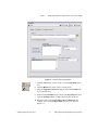
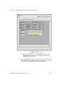
NI SignalExpress
Getting Started with NI SignalExpress
Tektronix ® Edition
Getting Started with NI SignalExpress Tektronix Edition
December 2005
374297A-01
TM
Support
Worldwide Technical Support and Product Information
ni.com
National Instruments Corporate Headquarters
11500 North Mopac Expressway
Austin, Texas 78759-3504
USA Tel: 512 683 0100
Worldwide Offices
Australia 1800 300 800, Austria 43 0 662 45 79 90 0, Belgium 32 0 2 757 00 20, Brazil 55 11 3262 3599,
Canada 800 433 3488, China 86 21 6555 7838, Czech Republic 420 224 235 774, Denmark 45 45 76 26 00,
Finland 385 0 9 725 725 11, France 33 0 1 48 14 24 24, Germany 49 0 89 741 31 30, India 91 80 51190000,
Israel 972 0 3 6393737, Italy 39 02 413091, Japan 81 3 5472 2970, Korea 82 02 3451 3400,
Lebanon 961 0 1 33 28 28, Malaysia 1800 887710, Mexico 01 800 010 0793, Netherlands 31 0 348 433 466,
New Zealand 0800 553 322, Norway 47 0 66 90 76 60, Poland 48 22 3390150, Portugal 351 210 311 210,
Russia 7 095 783 68 51, Singapore 1800 226 5886, Slovenia 386 3 425 4200, South Africa 27 0 11 805 8197,
Spain 34 91 640 0085, Sweden 46 0 8 587 895 00, Switzerland 41 56 200 51 51, Taiwan 886 02 2377 2222,
Thailand 662 278 6777, United Kingdom 44 0 1635 523545
For further support information, refer to the Technical Support and Professional Services appendix. To comment
on National Instruments documentation, refer to the National Instruments Web site at ni.com/info and enter
the info code feedback.
© 2005 National Instruments Corporation. All rights reserved.
Important Information
Warranty
The media on which you receive National Instruments software are warranted not to fail to execute programming instructions, due to defects
in materials and workmanship, for a period of 90 days from date of shipment, as evidenced by receipts or other documentation. National
Instruments will, at its option, repair or replace software media that do not execute programming instructions if National Instruments receives
notice of such defects during the warranty period. National Instruments does not warrant that the operation of the software shall be
uninterrupted or error free.
A Return Material Authorization (RMA) number must be obtained from the factory and clearly marked on the outside of the package before
any equipment will be accepted for warranty work. National Instruments will pay the shipping costs of returning to the owner parts which are
covered by warranty.
National Instruments believes that the information in this document is accurate. The document has been carefully reviewed for technical
accuracy. In the event that technical or typographical errors exist, National Instruments reserves the right to make changes to subsequent
editions of this document without prior notice to holders of this edition. The reader should consult National Instruments if errors are suspected.
In no event shall National Instruments be liable for any damages arising out of or related to this document or the information contained in it.
EXCEPT AS SPECIFIED HEREIN, NATIONAL INSTRUMENTS MAKES NO WARRANTIES, EXPRESS OR IMPLIED, AND SPECIFICALLY DISCLAIMS ANY WARRANTY OF
MERCHANTABILITY OR FITNESS FOR A PARTICULAR PURPOSE. CUSTOMER’S RIGHT TO RECOVER DAMAGES CAUSED BY FAULT OR NEGLIGENCE ON THE PART OF
NATIONAL INSTRUMENTS SHALL BE LIMITED TO THE AMOUNT THERETOFORE PAID BY THE CUSTOMER. NATIONAL INSTRUMENTS WILL NOT BE LIABLE FOR
DAMAGES RESULTING FROM LOSS OF DATA, PROFITS, USE OF PRODUCTS, OR INCIDENTAL OR CONSEQUENTIAL DAMAGES, EVEN IF ADVISED OF THE POSSIBILITY
THEREOF. This limitation of the liability of National Instruments will apply regardless of the form of action, whether in contract or tort, including
negligence. Any action against National Instruments must be brought within one year after the cause of action accrues. National Instruments
shall not be liable for any delay in performance due to causes beyond its reasonable control. The warranty provided herein does not cover
damages, defects, malfunctions, or service failures caused by owner’s failure to follow the National Instruments installation, operation, or
maintenance instructions; owner’s modification of the product; owner’s abuse, misuse, or negligent acts; and power failure or surges, fire,
flood, accident, actions of third parties, or other events outside reasonable control.
Copyright
Under the copyright laws, this publication may not be reproduced or transmitted in any form, electronic or mechanical, including photocopying,
recording, storing in an information retrieval system, or translating, in whole or in part, without the prior written consent of National
Instruments Corporation.
Trademarks
National Instruments, NI, ni.com, and LabVIEW are trademarks of National Instruments Corporation. Refer to the Terms of Use section
on ni.com/legal for more information about National Instruments trademarks.
Tektronix® and Tek are registered trademarks of Tektronix, Inc. Other product and company names mentioned herein are trademarks or trade
names of their respective companies.
Patents
For patents covering National Instruments products, refer to the appropriate location: Help»Patents in your software, the patents.txt file
on your CD, or ni.com/patents.
WARNING REGARDING USE OF NATIONAL INSTRUMENTS PRODUCTS
(1) NATIONAL INSTRUMENTS PRODUCTS ARE NOT DESIGNED WITH COMPONENTS AND TESTING FOR A LEVEL OF
RELIABILITY SUITABLE FOR USE IN OR IN CONNECTION WITH SURGICAL IMPLANTS OR AS CRITICAL COMPONENTS IN
ANY LIFE SUPPORT SYSTEMS WHOSE FAILURE TO PERFORM CAN REASONABLY BE EXPECTED TO CAUSE SIGNIFICANT
INJURY TO A HUMAN.
(2) IN ANY APPLICATION, INCLUDING THE ABOVE, RELIABILITY OF OPERATION OF THE SOFTWARE PRODUCTS CAN BE
IMPAIRED BY ADVERSE FACTORS, INCLUDING BUT NOT LIMITED TO FLUCTUATIONS IN ELECTRICAL POWER SUPPLY,
COMPUTER HARDWARE MALFUNCTIONS, COMPUTER OPERATING SYSTEM SOFTWARE FITNESS, FITNESS OF COMPILERS
AND DEVELOPMENT SOFTWARE USED TO DEVELOP AN APPLICATION, INSTALLATION ERRORS, SOFTWARE AND
HARDWARE COMPATIBILITY PROBLEMS, MALFUNCTIONS OR FAILURES OF ELECTRONIC MONITORING OR CONTROL
DEVICES, TRANSIENT FAILURES OF ELECTRONIC SYSTEMS (HARDWARE AND/OR SOFTWARE), UNANTICIPATED USES OR
MISUSES, OR ERRORS ON THE PART OF THE USER OR APPLICATIONS DESIGNER (ADVERSE FACTORS SUCH AS THESE ARE
HEREAFTER COLLECTIVELY TERMED “SYSTEM FAILURES”). ANY APPLICATION WHERE A SYSTEM FAILURE WOULD
CREATE A RISK OF HARM TO PROPERTY OR PERSONS (INCLUDING THE RISK OF BODILY INJURY AND DEATH) SHOULD
NOT BE RELIANT SOLELY UPON ONE FORM OF ELECTRONIC SYSTEM DUE TO THE RISK OF SYSTEM FAILURE. TO AVOID
DAMAGE, INJURY, OR DEATH, THE USER OR APPLICATION DESIGNER MUST TAKE REASONABLY PRUDENT STEPS TO
PROTECT AGAINST SYSTEM FAILURES, INCLUDING BUT NOT LIMITED TO BACK-UP OR SHUT DOWN MECHANISMS.
BECAUSE EACH END-USER SYSTEM IS CUSTOMIZED AND DIFFERS FROM NATIONAL INSTRUMENTS' TESTING
PLATFORMS AND BECAUSE A USER OR APPLICATION DESIGNER MAY USE NATIONAL INSTRUMENTS PRODUCTS IN
COMBINATION WITH OTHER PRODUCTS IN A MANNER NOT EVALUATED OR CONTEMPLATED BY NATIONAL
INSTRUMENTS, THE USER OR APPLICATION DESIGNER IS ULTIMATELY RESPONSIBLE FOR VERIFYING AND VALIDATING
THE SUITABILITY OF NATIONAL INSTRUMENTS PRODUCTS WHENEVER NATIONAL INSTRUMENTS PRODUCTS ARE
INCORPORATED IN A SYSTEM OR APPLICATION, INCLUDING, WITHOUT LIMITATION, THE APPROPRIATE DESIGN,
PROCESS AND SAFETY LEVEL OF SUCH SYSTEM OR APPLICATION.
Conventions
The following conventions are used in this manual:
<>
Angle brackets that contain numbers separated by an ellipsis represent
a range of values associated with a bit or signal name—for example,
AO <3..0>.
[]
Square brackets enclose optional items—for example, [response].
»
The » symbol leads you through nested menu items and dialog box options
to a final action. The sequence File»Page Setup»Options directs you to
pull down the File menu, select the Page Setup item, and select Options
from the last dialog box.
This icon denotes a note, which alerts you to important information.
bold
Bold text denotes items that you must select or click in the software, such
as menu items and dialog box options. Bold text also denotes parameter
names.
italic
Italic text denotes variables, emphasis, a cross reference, or an introduction
to a key concept. Italic text also denotes text that is a placeholder for a word
or value that you must supply.
monospace
Text in this font denotes text or characters that you should enter from the
keyboard, sections of code, programming examples, and syntax examples.
This font is also used for the proper names of disk drives, paths, directories,
programs, subprograms, subroutines, device names, functions, operations,
variables, filenames, and extensions.
Contents
Chapter 1
Introduction to NI SignalExpress Tektronix Edition
NI SignalExpress Tektronix Edition for the Design Lab...............................................1-1
Extending NI SignalExpress Tektronix Edition Projects with LabVIEW.....................1-2
Chapter 2
Getting Started with NI SignalExpress Tektronix Edition
Installing NI SignalExpress Tektronix Edition..............................................................2-1
Minimum System Requirements .....................................................................2-1
Installation Instructions ...................................................................................2-1
NI SignalExpress Tektronix Edition Version Availability ............................................2-2
NI SignalExpress Tektronix Edition Licensing Options ...............................................2-4
NI SignalExpress Tektronix Edition Base License .........................................2-4
NI Signal Express Tektronix Edition Professional License ............................2-4
Chapter 3
Connecting and Controlling Instruments
Tektronix DPO4000 Series Oscilloscopes.....................................................................3-1
Connecting over USB......................................................................................3-1
Connecting over Ethernet ................................................................................3-4
Tektronix AFG3000 Series Arbitrary/Function Generators ..........................................3-6
Connecting over USB......................................................................................3-6
Connecting over Ethernet ................................................................................3-8
Connecting over GPIB ....................................................................................3-10
Tektronix TDS3000 Series Oscilloscopes .....................................................................3-12
Connecting over Ethernet ................................................................................3-12
Connecting over GPIB ....................................................................................3-14
Chapter 4
Working with Projects
Loading a Project ...........................................................................................................4-1
Running a Project and Displaying Signals ....................................................................4-2
Configuring a Step .........................................................................................................4-4
Moving and Deleting Steps............................................................................................4-8
Handling Errors and Warnings ......................................................................................4-8
© National Instruments Corporation
v
Getting Started with NI SignalExpress Tektronix Edition
Contents
Chapter 5
Working with Signals
Graphing Signals ........................................................................................................... 5-1
Importing a Signal from a File ...................................................................................... 5-3
Aligning and Comparing Signals .................................................................................. 5-4
Signal Types in NI SignalExpress Tektronix Edition ................................................... 5-6
Exporting and Printing Signals...................................................................................... 5-7
Exporting Signals to Microsoft Excel ............................................................. 5-7
Printing Signals ............................................................................................... 5-7
Saving Signals as Images ................................................................................ 5-7
Saving Tektronix Scope Images ..................................................................... 5-7
Logging Data to a File .................................................................................... 5-7
Chapter 6
Performing Sweep Measurements
Defining Sweep Ranges and Outputs ............................................................................ 6-1
Plotting Sweep Results .................................................................................................. 6-4
Running Multi-Dimensional Sweeps ............................................................................ 6-6
Chapter 7
Extending NI SignalExpress Tektronix Edition Projects with LabVIEW
Importing LabVIEW VIs into NI SignalExpress Tektronix Edition as Steps............... 7-1
Chapter 8
Where to Go from Here
NI SignalExpress Tektronix Edition Sample Projects................................................... 8-1
Using Other Instruments with NI SignalExpress Tektronix Edition............................. 8-1
Related Documentation ................................................................................................. 8-1
Web Resources .............................................................................................................. 8-2
Appendix A
Technical Support and Professional Services
Getting Started with NI SignalExpress Tektronix Edition
vi
ni.com
Introduction to NI SignalExpress
Tektronix Edition
1
National Instruments provides innovative solutions for scientists and
engineers to build automated measurement systems based on
industry-standard computers and platforms. National Instruments develops
robust, industry-leading programming environments for automating
measurement systems, such as LabVIEW for graphical development,
LabWindows™/CVI™ for ANSI C programming, and Measurement Studio
for Microsoft Visual Studio programming. You can use these programming
tools with National Instruments measurement hardware and interfaces to
traditional instruments to build custom advanced virtual instrumentation
systems.
NI SignalExpress Tektronix Edition optimizes virtual instrumentation for
design and test engineers by offering instant interactive measurements that
require no programming. You can use NI SignalExpress Tektronix Edition
interactively to acquire, generate, analyze, compare, import, and save
signals. You can compare design data with measurement data in one step.
NI SignalExpress Tektronix Edition extends the ease of use and
performance of virtual instrumentation to those who must acquire or
analyze signals without programming applications. You also can extend the
functionality of NI SignalExpress Tektronix Edition by importing a custom
virtual instrument (VI) created in LabVIEW or by converting an
NI SignalExpress Tektronix Edition project to a LabVIEW block diagram
so you can continue development in the LabVIEW environment.
NI SignalExpress Tektronix Edition for the Design Lab
Tektronix and National Instruments have partnered to help increase your
productivity with the industry’s most seamless oscilloscope-to-computer
connectivity solution. NI SignalExpress Tektronix Edition is fully
interactive measurement acquisition, analysis, and documentation
© National Instruments Corporation
1-1
Getting Started with NI SignalExpress Tektronix Edition
Chapter 1
Introduction to NI SignalExpress Tektronix Edition
software. NI SignalExpress Tektronix Edition also includes the industry’s
first USB plug-and-play automatic configuration and connectivity. Using
NI SignalExpress Tektronix Edition, you can take advantage of the
following:
•
Ability to configure and connect Tektronix instruments with the
industry’s first, true USB plug-and-play connectivity solution.
•
An intuitive drag-and-drop user interface that does not require any
programming.
•
Capability to capture, transfer, and save measurement settings,
waveforms, and screen images.
•
Quickly import your simulated results and compare them against
actual measured results live on-screen.
•
More than 200 measurement, processing, analysis, and reporting
operations that perform in real time.
NI SignalExpress Tektronix Edition also comes with built-in support for
the following:
•
Tektronix DPO4000 and TDS3000 series oscilloscopes
•
Tektronix AFG3000 series arbitrary/function generator
•
Over 300 other common standalone instruments
Extending NI SignalExpress Tektronix Edition Projects
with LabVIEW
You can extend the functionality of NI SignalExpress Tektronix Edition
with LabVIEW when you build VIs with LabVIEW and import them into
NI SignalExpress Tektronix Edition to expand the built-in measurement
options.
Refer to Chapter 7, Extending NI SignalExpress Tektronix Edition Projects
with LabVIEW, for more information about importing LabVIEW VIs as
steps.
Getting Started with NI SignalExpress Tektronix Edition
1-2
ni.com
Getting Started with
NI SignalExpress Tektronix Edition
2
This chapter provides information about NI SignalExpress Tektronix
Edition system requirements, installation instructions, version availability,
and available licensing options.
Installing NI SignalExpress Tektronix Edition
Before you begin the exercises in this manual, you must install
NI SignalExpress Tektronix Edition on your computer. The
NI SignalExpress Tektronix Edition setup program installs the software in
10 minutes.
Minimum System Requirements
To run NI SignalExpress Tektronix Edition, National Instruments
recommends that your system meet the following requirements:
•
256 MB of memory (128 MB minimum)
•
Pentium 4 processor or equivalent (Pentium III or Celeron 600 MHz
minimum)
Installation Instructions
Complete the following steps to install NI SignalExpress Tektronix Edition
on Windows 2000/XP.
1.
National Instruments strongly recommends that you exit all programs
before you run the NI SignalExpress Tektronix Edition installer.
Applications that run in the background, such as virus scanning
utilities, might cause the installer to take longer than average to
complete.
2.
Log on as an administrator or as a user with administrator privileges.
3.
Insert the NI SignalExpress Tektronix Edition CD and follow the
instructions that appear on the screen.
© National Instruments Corporation
2-1
Getting Started with NI SignalExpress Tektronix Edition
Chapter 2
Getting Started with NI SignalExpress Tektronix Edition
Unless you specify another location during installation, the NI SignalExpress
Tektronix Edition installation program copies files to <Program Files>\National
Instruments\SignalExpressTekEd directory.
Note
4.
After installation, check the hard disk for viruses and enable any virus
detection programs you disabled.
The example projects you use with this manual are located in
<Program Files>\National Instruments\SignalExpressTekEd\
Examples\Tutorial. The solutions for each exercise are located in
<Program Files>\National Instruments\SignalExpressTekEd\
Examples\Tutorial\Solutions.
NI SignalExpress Tektronix Edition Version Availability
NI SignalExpress Tektronix Edition is available in both a professional and
base version. Refer to the following table for a list of features available in
each version.
Features that are not available in the NI SignalExpress Tektronix Edition base
version will work for 30 days from the first use of the software. After 30 days, if you use
any of these features, NI SignalExpress Tektronix Edition will only run for 10 minutes and
you cannot save projects. If you use only Tektronix-specific steps in a project, the software
functions as normal.
Note
Table 2-1. Differences in NI SignalExpress Tektronix Edition Professional and Base Versions
Professional
Base
✓
✓
✓
✓
✓
✓
✓
—
Instrument Support
DPO4000 Digital Phosphor
Oscilloscopes
AFG3000 Arbitrary/Function
Generators
TDS3000B Digital Phosphor
Oscilloscopes
Over 300 common standalone
instruments
Getting Started with NI SignalExpress Tektronix Edition
2-2
ni.com
Chapter 2
Getting Started with NI SignalExpress Tektronix Edition
Table 2-1. Differences in NI SignalExpress Tektronix Edition Professional and Base Versions (Continued)
Professional
Base
✓
✓
✓
✓
✓
✓
✓
✓
✓
✓
✓
—
Visualization and Documentation
Customizable graphing
Interactive cursors
Save signals to file
Print and export graphs
Drag and drop data into Microsoft
Excel, Word, and WordPad
Automated data collection
Signal Processing
✓
✓
✓
✓
✓
Software filters
Scalar and waveform math
Analog and digital conversion
Interactive signal comparisons
Load simulation data from PSPICE,
Multisim, and other SPICE
packages
—
—
—
—
—
Time and Frequency Measurements
✓
✓
✓
✓
✓
✓
Amplitude and level
Timing and transition
Power spectrum
Frequency response
Distortion measurements
Tone extraction
© National Instruments Corporation
2-3
—
—
—
—
—
—
Getting Started with NI SignalExpress Tektronix Edition
Chapter 2
Getting Started with NI SignalExpress Tektronix Edition
Table 2-1. Differences in NI SignalExpress Tektronix Edition Professional and Base Versions (Continued)
Professional
Base
Measurement Automation
✓
✓
Parameter sweeping
Limit testing
—
—
NI SignalExpress Tektronix Edition Licensing Options
This section is designed to assist you in understanding the licensing
policies for NI Signal Express Tektronix Edition. This document does not
replace the National Instruments Software License Agreement and should
only be used as a reference.
NI SignalExpress Tektronix Edition Base License
The unlicensed version of NI SignalExpress Tektronix Edition gives you
access to all features in Table 2-1 for 30 days. After that period, NI
SignalExpress Tektronix Edition runs in unlicensed mode. If you do not
activate a valid license within 30 days and you create a project that contains
licensed steps, the following occurs:
Note
Tektronix-specific steps are not licensed steps.
•
Each time you drop a step that is licensed or not Tektronix-specific, a
dialog box prompts you to activate the software.
•
You cannot save a project.
•
Projects close after 10 minutes.
Refer to the National Instruments Web site at ni.com/tek to purchase NI
SignalExpress Tektronix Edition professional version.
NI Signal Express Tektronix Edition Professional License
The professional license provides you with the full functionality of NI
SignalExpress Tektronix Edition, as shown in Table 2-1. You can activate
NI SignalExpress Tektronix Edition professional version using the
National Instruments License Manager or the NI SignalExpress Tektronix
Edition installer.
Getting Started with NI SignalExpress Tektronix Edition
2-4
ni.com
Connecting and Controlling
Instruments
3
NI SignalExpress Tektronix Edition provides native support for the
Tektronix DPO4000 and the TDS3000 series oscilloscopes and AFG3000
series signal generators. This chapter covers the process of connecting
instruments to the PC and performing signal generation and acquisition
from within NI SignalExpress Tektronix Edition.
NI SignalExpress Tektronix Edition also supports over 300 of the most
common standalone instruments, including the majority of instruments in
the Tektronix oscilloscope and signal generator product lines. Refer to
Using Other Instruments with NI SignalExpress Tektronix Edition in
Chapter 8, Where to Go from Here, for more information about controlling
other instruments.
Tektronix DPO4000 Series Oscilloscopes
Connecting over USB
With built-in USB plug-and-play capabilities in Windows XP,
NI SignalExpress Tektronix Edition automatically detects when a
Tektronix DPO4000 series oscilloscope connects to the PC and allows you
to immediately control the oscilloscope and acquire signals from the
oscilloscope. Complete the following steps to connect the Tektronix
DPO4000 series oscilloscope:
1.
Turn on the Tektronix DPO4000 series oscilloscope.
2.
Using a USB device cable, plug the Type B, device-side connector into
the USB device port on the back of the Tektronix DPO4000 series
oscilloscope, as shown in Figure 3-1. Connect the Type A, host-side
connector to your computer.
© National Instruments Corporation
3-1
Getting Started with NI SignalExpress Tektronix Edition
Chapter 3
Connecting and Controlling Instruments
Figure 3-1. DPO4000 USB Connection
After completing the connections, Windows detects that you have
connected a new device to the computer and prompts you to install the
driver for the Tektronix DPO4000 series oscilloscope.
3.
Click the Next button on the following dialog boxes to finish the
installation of the Tektronix DPO4000 series oscilloscope driver.
You only need to perform Step 3 the first time you plug the Tektronix DPO4000
series oscilloscope into the computer. Subsequent connections immediately launch the
dialog box discussed in Step 4.
Note
4.
Windows prompts you with a dialog box, as shown in Figure 3-2,
indicating that the Tektronix DPO4000 series oscilloscope has been
detected and prompts for the action to take. If Control Instrument
using NI SignalExpress - Tektronix Edition is not selected, click
Control Instrument using NI SignalExpress - Tektronix Edition
and then click the OK button.
Getting Started with NI SignalExpress Tektronix Edition
3-2
ni.com
Chapter 3
Connecting and Controlling Instruments
Figure 3-2. USB Plug-and-Play Dialog Box
5.
© National Instruments Corporation
NI SignalExpress Tektronix Edition launches and provides a live view
of the Tektronix DPO4000 series oscilloscope, as shown in Figure 3-3.
3-3
Getting Started with NI SignalExpress Tektronix Edition
Chapter 3
Connecting and Controlling Instruments
Figure 3-3. Live Acquisition from Tektronix DPO4000 Series Oscilloscope
Connecting over Ethernet
Before you begin this section, refer to the DPO4000 Series Digital
Phosphor Oscilloscopes User Manual to properly connect and configure
your Tektronix DPO4000 series oscilloscope for communication over
Ethernet. After you connect and configure the oscilloscope, complete the
following steps to access the Tektronix DPO4000 series oscilloscope from
within NI SignalExpress Tektronix Edition:
1.
Launch NI SignalExpress Tektronix Edition by selecting Start»
All Programs»National Instruments»SignalExpress Tektronix
Edition»SignalExpress Tektronix Edition.
2.
Click the Add Step button, shown at left, and select
Tektronix»Acquire Signals»Tek DPO4000. The Tektronix
Getting Started with NI SignalExpress Tektronix Edition
3-4
ni.com
Chapter 3
Connecting and Controlling Instruments
DPO4000 series oscilloscope Step Setup dialog box launches, as
shown in Figure 3-4.
Figure 3-4. Autodetect Tektronix DPO4000 Series Oscilloscope Connected
Ethernet Connection
3.
If you know the IP address of the connected Tektronix DPO4000 series
oscilloscope, enter it in the Select instrument to use drop-down box
on the VISA Resource tab.
If you do not know the IP address, click the Autodetect button on
the VISA Resource tab to scan the local subnet for a connected
Tektronix DPO4000 series oscilloscope. If a Tektronix DPO4000
series oscilloscope is found, NI SignalExpress Tektronix Edition
© National Instruments Corporation
3-5
Getting Started with NI SignalExpress Tektronix Edition
Chapter 3
Connecting and Controlling Instruments
displays the instrument address, connects to the Tektronix DPO4000
series oscilloscope, and performs one waveform acquisition.
You must manually enter the instrument address when connecting to a
Tektronix DPO4000 series oscilloscope that is not on the local subnet. Refer to the
NI Express Workbench Help for information about how to manually connect to a
Tektronix DPO4000 series oscilloscope by selecting Help»Express Workbench Help,
clicking the Search tab, and entering “Tek DPO4000”.
Note
4.
Click the Run button, shown at left, to continually acquire a signal
from the Tektronix DPO4000 series oscilloscope.
Tektronix AFG3000 Series Arbitrary/Function
Generators
Connecting over USB
With built-in USB plug-and-play capabilities, NI SignalExpress Tektronix
Edition automatically detects when a Tektronix AFG3000 series
arbitrary/function generator connects to the PC and allows you to
immediately control and generate signals. Complete the following steps to
connect the Tektronix AFG3000 series arbitrary/function generator
over USB:
1.
Turn on the Tektronix AFG3000 series arbitrary/function generator.
2.
Using a USB device cable, plug the Type B, device-side connector into
the USB device port on the back of the Tektronix AFG3000 series
arbitrary/function generator. Connect the Type A, host-side connector
to your computer.
After you complete the connections, Windows detects that you have
connected a new device to the computer and prompts you to install the
driver for the AFG3000.
3.
Click the Next button in the dialog boxes that follow to finish the
installation of the Tektronix AFG3000 series arbitrary/function
generator.
You only need to perform Step 3 the first time the you plug a Tektronix AFG3000
series arbitrary/function generator into the computer. Subsequent connections immediately
launch the dialog box discussed in Step 4.
Note
Getting Started with NI SignalExpress Tektronix Edition
3-6
ni.com
Chapter 3
4.
Connecting and Controlling Instruments
Windows prompts you with a dialog box, as shown in Figure 3-5,
indicating that the Tektronix AFG3000 series arbitrary/function
generator has been detected and prompts for the action to take. If
Control Instrument using NI SignalExpress - Tektronix Edition is
not selected, click Control Instrument using NI SignalExpress Tektronix Edition and then click the OK button.
Figure 3-5. USB Plug-and-Play Dialog Box
5.
© National Instruments Corporation
NI SignalExpress Tektronix Edition launches and provides a live
connection to the Tektronix AFG3000 series arbitrary/function
generator, as shown in Figure 3-6.
3-7
Getting Started with NI SignalExpress Tektronix Edition
Chapter 3
Connecting and Controlling Instruments
Figure 3-6. Live Acquisition from Tektronix AFG3000 Series
Arbitrary/Function Generator
Connecting over Ethernet
Before you begin this section, refer to the AFG3000 Series Quick Start
User Manual to properly connect and configure the Tektronix AFG3000
series arbitrary/function generator for communication over Ethernet. After
you connect and configure the arbitrary/function generator, complete the
following steps to access the Tektronix AFG3000 series arbitrary/function
generator from within NI SignalExpress Tektronix Edition:
1.
Launch NI SignalExpress Tektronix Edition by selecting Start»
All Programs»National Instruments»SignalExpress Tektronix
Edition»SignalExpress Tektronix Edition.
Getting Started with NI SignalExpress Tektronix Edition
3-8
ni.com
Chapter 3
2.
Connecting and Controlling Instruments
Click the Add Step button, shown at left, and select Tektronix»
Generate Signals»Tek AFG3000. The Tektronix AFG3000 series
arbitrary/function generator Step Setup dialog box launches, as shown
in Figure 3-7.
Figure 3-7. Autodetect Tektronix AFG3000 Series Arbitrary/Function Generator
Ethernet Connection
3.
© National Instruments Corporation
Click the Autodetect button on the VISA Resource tab to scan
the local subnet for connected Tektronix AFG3000 series
arbitrary/function generators. If NI SignalExpress Tektronix Edition
detects a Tektronix AFG3000 series arbitrary/function generator on
the local subnet, NI SignalExpress Tektronix Edition displays the
instrument address and connects to the Tektronix AFG3000 series
arbitrary/function generator.
3-9
Getting Started with NI SignalExpress Tektronix Edition
Chapter 3
Connecting and Controlling Instruments
You must manually enter the instrument address when you connect to a Tektronix
AFG3000 series arbitrary/function generator that is not on the local subnet. Refer to the
NI Express Workbench Help for information about how to manually connect to a Tektronix
AFG3000 series arbitrary/function generator by selecting Help»Express Workbench
Help, clicking the Search tab, and entering “Tek AFG3000”.
Note
4.
Click the Run button, shown at left, to start signal generation using the
Tektronix AFG3000 series arbitrary/function generator.
Connecting over GPIB
Complete the following steps to connect and control the Tektronix
AFG3000 series arbitrary/function generator over GPIB:
1.
Connect the Tektronix AFG3000 series arbitrary/function generator to
your computer using a GPIB cable.
2.
Launch NI SignalExpress Tektronix Edition by selecting Start»
All Programs»National Instruments»SignalExpress Tektronix
Edition»SignalExpress Tektronix Edition.
3.
Click the Add Step button, shown at left, and select
Tektronix»Generate Signals»Tek AFG3000. The Tektronix
AFG3000 series arbitrary/function generator Step Setup dialog box
launches, as shown in Figure 3-8.
Getting Started with NI SignalExpress Tektronix Edition
3-10
ni.com
Chapter 3
Connecting and Controlling Instruments
Figure 3-8. Autodetect Tektronix AFG3000 Series Arbitrary Function Generator
GPIB Connection
4.
Click the Autodetect button on the VISA Resource tab to find and
connect to the Tektronix AFG3000 series arbitrary/function generator.
5.
Click the Run button, shown at left, to start signal generation with the
Tektronix AFG3000 series arbitrary/function generator.
© National Instruments Corporation
3-11
Getting Started with NI SignalExpress Tektronix Edition
Chapter 3
Connecting and Controlling Instruments
Tektronix TDS3000 Series Oscilloscopes
Connecting over Ethernet
Before you begin this section, refer to the TDS3000 Series User Manual to
properly connect and configure your Tektronix TDS3000 series
oscilloscope for communication over Ethernet. After you connect and
configure the oscilloscope, complete the following steps to access the
Tektronix TDS3000 series oscilloscope from within NI SignalExpress
Tektronix Edition:
1.
Launch NI SignalExpress Tektronix Edition by selecting Start»
All Programs»National Instruments»SignalExpress Tektronix
Edition»SignalExpress Tektronix Edition.
2.
Click the Add Step button, shown at left, and select Tektronix»
Acquire Signals»Tek TDS3000. The Tektronix TDS3000 series
oscilloscope Step Setup dialog box launches, as shown in Figure 3-9.
Getting Started with NI SignalExpress Tektronix Edition
3-12
ni.com
Chapter 3
Connecting and Controlling Instruments
Figure 3-9. Autodetect Tektronix TDS3000 Series Oscilloscopes Ethernet Connection
3.
If you know the IP address of the connected Tektronix TDS3000 series
oscilloscope, enter it in the Select instrument to use drop-down box
on the VISA Resource tab.
If you do not know the IP address, click the Autodetect button to scan
the local subnet for connected Tektronix TDS3000 series
oscilloscopes. If NI SignalExpress Tektronix Edition detects a
Tektronix TDS3000 series oscilloscope on the local subnet,
NI SignalExpress Tektronix Edition displays the instrument address,
connects to the Tektronix TDS3000 series oscilloscope, and performs
one waveform acquisition.
© National Instruments Corporation
3-13
Getting Started with NI SignalExpress Tektronix Edition
Chapter 3
Connecting and Controlling Instruments
You must manually enter the instrument address when connecting to a
Tektronix TDS3000 series oscilloscope that is not on the local subnet. Refer to the
NI Express Workbench Help for information on how to manually connect to a
Tektronix TDS3000 series oscilloscope by selecting Help»Express Workbench Help,
clicking the Search tab, and entering “Tek TDS3000”.
Note
4.
Click the Run button, shown at left, to continually acquire from the
Tektronix TDS3000 series oscilloscope.
Connecting over GPIB
Complete the following steps to connect and control the Tektronix
TDS3000 series oscilloscope over GPIB:
1.
Connect the Tektronix TDS3000 series oscilloscope to your computer
using a GPIB cable.
2.
Launch NI SignalExpress Tektronix Edition by selecting Start»
All Programs»National Instruments»SignalExpress Tektronix
Edition»SignalExpress Tektronix Edition.
3.
Click the Add Step button, shown at left, and select Tektronix»
Acquire Signals»Tek TDS3000. The Tektronix TDS3000 series
oscilloscope Step Setup dialog box launches, as shown in Figure 3-10.
Getting Started with NI SignalExpress Tektronix Edition
3-14
ni.com
Chapter 3
Connecting and Controlling Instruments
Figure 3-10. Autodetect Tektronix TDS3000 Series Oscilloscopes GPIB Connection
4.
Click the Autodetect button on the VISA Resource tab to find and
connect to the Tektronix TDS3000 series oscilloscope.
5.
Click the Run button, shown at left, to start signal acquisition with the
Tektronix TDS3000 series oscilloscope.
© National Instruments Corporation
3-15
Getting Started with NI SignalExpress Tektronix Edition
4
Working with Projects
You can use NI SignalExpress Tektronix Edition to define measurement
procedures by adding and configuring steps in an interactive measurement
environment. A step is a configurable function that acquires, generates,
analyzes, loads, or stores signals. Steps process input signals and produce
output signals. You can configure the operation of a step by specifying
values in a Step Setup dialog box. A saved sequence of configured steps is
an NI SignalExpress Tektronix Edition project. This chapter teaches you
about the basic layout of NI SignalExpress Tektronix Edition. You learn
how to load and run existing projects and how to configure steps in these
projects.
Loading a Project
Complete the following steps to load a sample project in NI SignalExpress
Tektronix Edition:
1.
2.
Launch NI SignalExpress Tektronix Edition by selecting Start»
All Programs»National Instruments»SignalExpress Tektronix
Edition»SignalExpress Tektronix Edition.
Select File»Open Project, navigate to the
<SignalExpressTekEd>\Examples\Tutorial directory, and
double-click First Project.wbp. Workbench projects refer to the
Express Workbench framework in which NI SignalExpress Tektronix
Edition resides.
3.
© National Instruments Corporation
Examine the dialog box that launches, as shown in Figure 4-1, to learn
about the different components of NI SignalExpress Tektronix Edition.
4-1
Getting Started with NI SignalExpress Tektronix Edition
Chapter 4
Working with Projects
1
2
3
4
6
5
1
2
Execution control buttons
Step
3
4
Input
Output
5
6
Project View
Data View
Figure 4-1. First Project.wbp
The left pane is the Project View, which presents the order of
operations, or steps, for the project. The right pane is the Data View,
which displays the signal that the project generates and analyzes.
Running a Project and Displaying Signals
NI SignalExpress Tektronix Edition uses the following two execution
modes: Run and Run Once. When you click the Run button,
NI SignalExpress Tektronix Edition executes all steps in a project
continuously until you click the Stop button. The Stop button is visible in
place of the Run button when a project runs. While steps in the project
execute, the Data View updates continuously. While the project runs, you
can change the measurement configurations and view the results
immediately. If you modify the configuration of steps while a project runs,
Getting Started with NI SignalExpress Tektronix Edition
4-2
ni.com
Chapter 4
Working with Projects
NI SignalExpress Tektronix Edition gives you direct, immediate feedback
on the changes you make. When you click the Run Once button,
NI SignalExpress Tektronix Edition executes all steps in the project one
time.
Figure 4-2. NI SignalExpress Tektronix Edition Project and Data Views
© National Instruments Corporation
4-3
Getting Started with NI SignalExpress Tektronix Edition
Chapter 4
Working with Projects
Configuring a Step
A step is a configurable function that acquires, generates, analyzes, loads,
or stores signals. Steps process input signals and produce output signals.
You can configure the operation of a step in NI SignalExpress Tektronix
Edition by specifying values in the Step Setup dialog box for that step.
While a project runs, you can modify the configuration of steps to view
immediate feedback on the changes and adjust the measurements until you
achieve the results you need.
Complete the following steps to configure the Distortion and Amplitude
and Levels steps:
1.
Double-click the Distortion step in the Project View. The Step Setup
dialog box for the Distortion step appears, as shown in Figure 4-3. If
the Step Setup dialog box is docked, click the Dock button, shown at
left, on the toolbar to undock the Step Setup dialog box.
Getting Started with NI SignalExpress Tektronix Edition
4-4
ni.com
Chapter 4
Working with Projects
Figure 4-3. Distortion Step Setup Dialog Box
On the Configuration tab, the settings indicate that the Distortion step
receives a time-domain waveform signal as an input, performs a power
spectrum on the signal to convert it to the frequency domain, and
computes the total harmonic distortion (THD) and fundamental
frequency of the signal. The Distortion step generates the following
three measurements as outputs: the spectrum, the THD, and the
fundamental frequency of the original time-domain waveform input.
2.
© National Instruments Corporation
If the context help does not appear on the right side of the Step Setup
dialog box, click the Show Help button, shown at left, to display
complete reference information about the step.
4-5
Getting Started with NI SignalExpress Tektronix Edition
Chapter 4
Working with Projects
The upper half of the context help displays information about the step,
and the lower half of the context help displays information about an
object when you hover over the object.
3.
On the Configuration tab, select Fundamental Tone from the
Export signals (THD) pull-down menu. The operation of the step
changes from displaying the frequency-domain spectrum of the entire
input signal to displaying only the frequency spectrum of the
fundamental tone of the input signal. The signals in the top half of the
Step Setup dialog box update to reflect the change you made.
4.
Select Harmonics Only from the Export signals (THD) pull-down
menu. The step changes to export only the spectrum of the harmonic
signals from the input signal. Both the output signal of the Distortion
step and the graph in the Data View update to reflect the change you
made.
5.
Click the Amplitude and Levels step in the Project View. The Step
Setup dialog box changes from displaying the configuration of the
Distortion step to displaying the configuration of the Amplitude and
Levels step.
6.
Click the Input/Output tab to display the list of possible inputs and
outputs for this step, as shown in Figure 4-4.
Getting Started with NI SignalExpress Tektronix Edition
4-6
ni.com
Chapter 4
Working with Projects
Figure 4-4. Amplitude and Levels Step Setup Dialog Box
7.
Place checkmarks in the Export +peak value, Export -peak value,
and Export peak-peak value checkboxes to configure the Amplitude
and Levels step to return three additional measurements. Three
additional outputs are now visible in the Project View.
8.
Click the Close button, shown at left, in the Step Setup dialog box to
close the Amplitude and Levels Step Setup dialog box.
9.
Drag the three new outputs +peak, -peak, and peak-peak from the
Project View to the Data View to display the scalar measurements.
10. Click the Stop button, shown at left, to stop the project.
When you click the Stop button, the project stops running after
completing the current cycle of operations, or the current iteration.
© National Instruments Corporation
4-7
Getting Started with NI SignalExpress Tektronix Edition
Chapter 4
Working with Projects
Clicking the Abort button completely stops the project without
finishing the current iteration.
11. Select File»Save Project As and save the project as My First
Project.wbp in the <SignalExpressTekEd>\Examples\
Tutorial directory.
12. Select File»Close Project to close the project.
Moving and Deleting Steps
The steps in NI SignalExpress Tektronix Edition projects depend on input
data, which means steps can operate only on signals exported from
previous steps in the Project View. When you click the Input signal
pull-down menu in the Step Setup dialog box of a step, the menu displays
only compatible signals exported from a previous step. When the output of
a step becomes the input of another step, the steps become dependent on
each other, and the two steps execute sequentially at the same rate. The first
step generates an output signal that the second step must receive as an input
before the step can execute.
You can move a step within a project by dragging the step up or down in the
Project View. You can delete a step by right-clicking the step in the Project
View and selecting Delete from the shortcut menu. However, when you
move or delete a step, the status of signals in the project changes. For
example, if you delete a step that generates output signals, the operation of
the project breaks if any of the deleted output signals are inputs for other
steps, and an error indicator appears in the Project View. If you move a step
lower in the project, the output signals of the step are not available as inputs
to any of the previous steps.
You also can cut, copy, and paste steps within a project by pressing the
<Ctrl-X>, <Ctrl-C>, and <Ctrl-V> keys, respectively, or by right-clicking
a step in the Project View and selecting Cut, Copy, Paste Before, or Paste
After from the shortcut menu.
Handling Errors and Warnings
If an error occurs while a project runs, an error indicator, shown at left,
appears in the Project View on the step that encountered the error.
Double-click the step with the error to display an error description across
the bottom of the Step Setup dialog box. Click the Details button to the
right of the error description to display the full error description.
Getting Started with NI SignalExpress Tektronix Edition
4-8
ni.com
Chapter 4
Working with Projects
NI SignalExpress Tektronix Edition logs all errors and warnings in the
Event Log while a project runs. To display the Event Log, select
View»Event Log and click the Event Log tab in the Data View area. Refer
to the NI Express Workbench Help for more information about errors and
warnings by selecting Help»Express Workbench Help, clicking the
Search tab, and entering errors.
© National Instruments Corporation
4-9
Getting Started with NI SignalExpress Tektronix Edition
5
Working with Signals
You can use NI SignalExpress Tektronix Edition to generate and analyze
signals to evaluate designs without programming. This chapter teaches you
how to work with signals in NI SignalExpress Tektronix Edition, including
how to plot signals on graphs, import signals from a file, interactively align
and compare two signals, and save signals to a file.
Graphing Signals
Complete the following steps to plot signals in a sample project and
examine the signals visually using cursors:
1.
Select File»Open Project, navigate to the
<SignalExpressTekEd>\Examples\Tutorial directory, and
double-click Signals.wbp. This project configures the Create Signal
step to create a square wave signal and the Filter step to perform a
lowpass Butterworth filter.
2.
Drag the step signal output of the Create Signal step to the Data View.
3.
Drag the filtered step output of the Filter step to the Data View.
You can plot signals of the same signal type on the same graph. Both
the step signal and the filtered step signal are time-domain signals, so
they appear on the same graph. If you want to plot signals of different
types, drag the signals to the same graph and NI SignalExpress
Tektronix Edition creates a new graph.
4.
Click the Add Display button, shown at left, on the toolbar to create a
new graph.
5.
Drag the filtered step output of the Filter step to the new graph.
6.
Right-click the new graph and select Cursors from the shortcut menu
to display two interactive cursors, as shown in Figure 5-1.
© National Instruments Corporation
5-1
Getting Started with NI SignalExpress Tektronix Edition
Chapter 5
Working with Signals
Figure 5-1. Signals.wbp
As you drag the cursors, NI SignalExpress Tektronix Edition displays
the x and y values of the cursors in the cursor table at the bottom of the
Data View.
7.
Right-click the graphs to view other operations in the shortcut menu.
If you have multiple signals on a single graph and one signal obscures
another, you can change the order of the signals. If you run a project
continuously but you want to view the data from a particular execution
iteration, you can pause the display by right-clicking the Data View,
selecting Display Update from the shortcut menu, and selecting
Always Update to remove the checkmark next to it. You also can add
or remove displays and add or remove signals.
Getting Started with NI SignalExpress Tektronix Edition
5-2
ni.com
Chapter 5
8.
Working with Signals
Select File»Save Project As and save the project as My Signals.wbp
in the <SignalExpressTekEd>\Examples\Tutorial directory.
Importing a Signal from a File
You can import signals from standard file formats such as ASCII, comma
or tab-delimited files, and LabVIEW measurement data files (.lvm). You
also can import signals from simulated results of EDA tools such as SPICE
simulators.
Complete the following steps to import a signal from a file:
1.
Right-click the Project View and select Analog»Load/Save Signals»
Load from ASCII from the shortcut menu.
2.
Click the Browse button, shown at left, in the Step Setup dialog box,
navigate to the <Program Files>\National Instruments\
SignalExpressTekEd\Examples\Tutorial directory, and
double-click Step Response.txt. This step parses an ASCII file
and displays the signals in the file.
In the File preview section, Column 1 shows the time stamp data, and
Column 2 shows the actual voltage values of the signal.
3.
Click the Import Signals tab to display the available signals in the file.
4.
Place a checkmark in the Column 2 checkbox to import the signal, and
remove the checkmark from the Column 1 checkbox. The Step Setup
dialog box displays a preview of the signal in the Imported Signal
section.
5.
Select Column 1 from the Input X values pull-down menu to set the
x-axis data of the waveform to the appropriate values.
6.
Click the Close button to close the Step Setup dialog box.
7.
Right-click the Column 2 output in the Project View and select
Rename from the shortcut menu.
8.
Enter step response and press the <Enter> key to rename the
output.
9.
Drag the step response output of the Load from ASCII step to the
lower graph. A dialog box launches because the two signals come from
different sources and run at different rates.
10. Click the Yes button to display both signals on the same graph. The
filtered step signal resembles the rising edge of the step response
output, as shown in Figure 5-2.
© National Instruments Corporation
5-3
Getting Started with NI SignalExpress Tektronix Edition
Chapter 5
Working with Signals
Figure 5-2. Signals of My Signals.wbp
11. Select File»Save Project to save the project.
Aligning and Comparing Signals
Although the filtered step signal and the step response output both show
an overshoot in the rising edge, assessing the similarity between the two
is difficult because the signals come from different sources and vary in
amplitude and timing. However, you can use the Interactive Alignment step
to align and compare two signals, so you can choose which type of
information you want to export from the operation to use in the project.
Getting Started with NI SignalExpress Tektronix Edition
5-4
ni.com
Chapter 5
Working with Signals
Complete the following steps to align two signals in the My Signals.wbp
project:
1.
Right-click the step response output and select Send To»Analog»
Processing»Interactive Alignment from the shortcut menu to pass
the step response signal from the Load from ASCII step to the
Interactive Alignment step.
The step selects the two most recent signals from the project to use as
inputs and displays the signals on the graph of the Step Setup dialog
box, as shown in Figure 5-3.
Figure 5-3. Interactive Alignment Step Setup Dialog Box
When you add a step to a project, NI SignalExpress Tektronix Edition
selects input signals based on the signal types the step can accept.
© National Instruments Corporation
5-5
Getting Started with NI SignalExpress Tektronix Edition
Chapter 5
Working with Signals
For example, the Interactive Alignment step can operate only on
time-domain waveform signals. Therefore, the step selects the last
two time-domain signals created in the project as inputs. To change the
input signals for a step, select different signals from the pull-down
menu of compatible signals in the Input/Output tab of the Step Setup
dialog box.
2.
Click the red signal and drag it within the graph. You can drag, expand,
and contract signals on the graph.
3.
Try to align the rising edges of the two signals by dragging a signal
within the graph. Click a signal to set an anchor point and press and
hold the <Alt> key while you click and drag the signal around the
anchor point. This stretches the signal in the x- and y- directions.
On the Alignment tab of the Step Setup dialog box, the step computes
and displays the x- and y-gain and x- and y-offset values you need to
achieve alignment specifications as you drag the signals.
4.
Select Auto - Step from the Mode pull-down menu to align the
signals. NI SignalExpress Tektronix Edition bases this alignment
mode on built-in algorithms.
The lower graph in the Step Setup dialog box displays the difference
between the two signals.
5.
On the Input/Output tab, place a checkmark in the Export aligned
signals checkbox to add the signals to the outputs of the step.
6.
Click the Close button to close the Step Setup dialog box.
7.
Click the Add Display button, shown at left, to add a third graph.
8.
Drag the aligned reference and aligned test outputs of the Interactive
Alignment step to the new graph to view the aligned signals.
9.
Select File»Save Project to save the project.
Signal Types in NI SignalExpress Tektronix Edition
Some steps, such as the Arithmetic step, can operate on multiple signal
types. For example, you can use the Arithmetic step to operate on
time-domain or frequency-domain waveforms. The Arithmetic step
changes behavior based on the type of input signals you select for the step.
For example, if you add two time-domain signals, NI SignalExpress
Tektronix Edition adds only their amplitudes. However, if you add two
frequency-domain phase signals, NI SignalExpress Tektronix Edition adds
the appropriate phase shift.
Getting Started with NI SignalExpress Tektronix Edition
5-6
ni.com
Chapter 5
Working with Signals
Refer to the NI Express Workbench Help for more information by selecting
Help»Express Workbench Help, clicking the Search tab, and entering
“signal types”.
Exporting and Printing Signals
NI SignalExpress Tektronix Edition offers several documentation features
so you can continue analysis in another software application, such as
Microsoft Excel or the report generation tool in NI DIAdem. These features
can help you document the data from NI SignalExpress Tektronix Edition
in reports.
Exporting Signals to Microsoft Excel
To export signal data to Microsoft Excel, launch Microsoft Excel and drag
the output signal of a step in NI SignalExpress Tektronix Edition to a
Microsoft Excel spreadsheet.
Printing Signals
To print an image of a graph, right-click the Data View and select
Export»Print Display from the shortcut menu.
Saving Signals as Images
To save an image of a graph as a.png file, right-click the Data View and
select Export»Save as Image from the shortcut menu. You can import a
.png file into Microsoft Word or any other documentation tool.
Saving Tektronix Scope Images
To save an image from your scope to a.png file, right-click the Utilities
menu in the Step Setup dialog box and select Save Image. You can import
a.png file into Microsoft Word or any other documentation tool.
Logging Data to a File
You can print graphs of signals and export or save signal data to view it in
spreadsheet applications.
Complete the following steps to save a signal to a file:
1.
© National Instruments Corporation
Click the Add Step button and select Analog»Load/Save Signals»
Save to ASCII/LVM.
5-7
Getting Started with NI SignalExpress Tektronix Edition
Chapter 5
Working with Signals
2.
Click the Signals tab in the Step Setup dialog box and select filtered
step from the Input Data pull-down menu.
3.
Select Overwrite from the If file already exists pull-down menu.
4.
Select Generic ASCII (.txt) from the Export file type pull-down
menu. You can use a Load/Save Signals step to save data to a file every
time the project runs.
5.
On the File Settings tab, save the file to <SignalExpressTekEd>\
Examples\Tutorial\filtered signal.txt.
6.
Click the Close button to close the Step Setup dialog box.
7.
Select File»Save Project to save the project.
8.
Select File»Close Project to close the project.
Getting Started with NI SignalExpress Tektronix Edition
5-8
ni.com
6
Performing Sweep
Measurements
You can use NI SignalExpress Tektronix Edition to automate
measurements to characterize and validate designs by creating sweep
operations. You can use the sweep measurements to gather data from
designs over a range of conditions to document the performance of the
designs. For example, you can use sweep operations to vary the frequency
of a stimulus signal or vary the level of a supply voltage while taking
measurements to characterize designs.
This chapter teaches you how to set up sweep operations using the Sweep
step in NI SignalExpress Tektronix Edition. You learn how to characterize
the performance of a filter by sweeping through a range of frequency values
and measuring the output of the filter. You also learn how to display sweep
results and perform multi-dimensional sweeps for more complex
measurements.
Defining Sweep Ranges and Outputs
You can use the Sweep step in NI SignalExpress Tektronix Edition to
define automated measurements for complex, repeatable sweep operations.
Complete the following steps to define a frequency range in a sample
project to sweep through a filter:
1.
Select File»Open Project, navigate to the
<SignalExpressTekEd>\Examples\Tutorial directory, and
double-click Sweep.wbp.
2.
Click the Run button, shown at left, to run the project.
The project generates a sine wave stimulus signal using the Create
Signal step, passes it through a bandpass elliptic filter using the Filter
step, measures the RMS level of the filter output using the Amplitude
and Levels step, and converts the level to decibels (dB) using the
Formula step. The Filter step acts as a simulated unit under test (UUT),
so the project does not use instrumentation. However, you also can
sweep physical signals that a Tektronix signal generator generates.
© National Instruments Corporation
6-1
Getting Started with NI SignalExpress Tektronix Edition
Chapter 6
Performing Sweep Measurements
3.
Click the Add Step button, shown at left, and select
Operations»Sweep.
4.
Click the Add button in the Step Setup dialog box to display the list
of sweep parameters from each step in the project, as shown in
Figure 6-1.
Figure 6-1. Sweep Parameter Selection Dialog Box
5.
Select the Frequency (Hz) parameter under Create Signal: stimulus
signal (sinewave) and click the OK button.
6.
On the Sweep Configuration tab, select Exponential from the Type
pull-down menu.
7.
Enter 1k in the Start Frequency (Hz) spin control, and enter 40k in
the Stop Frequency (Hz) spin control.
8.
Enter 150 in the Number of points spin control.
The Sweep Configuration tab should appear as shown in Figure 6-2.
Getting Started with NI SignalExpress Tektronix Edition
6-2
ni.com
Chapter 6
Performing Sweep Measurements
Figure 6-2. Sweep Step Setup Dialog Box
You use the Sweep step to specify a range of values to iterate through
the Frequency (Hz) parameter of the Create Signal step. The Create
Signal step uses the defined frequency range to generate a sine wave at
each of these frequencies. However, you can use the Sweep step to
sweep any sweepable parameter value of any sweepable step in a
project.
9.
Click the Sweep Output tab.
10. Click the Add button to display the list of sweep outputs from each
step in the project.
11. Select the response amplitude in dB output under Formula (Scalar)
and click the OK button to plot this measurement against the swept
Frequency (Hz) parameter.
© National Instruments Corporation
6-3
Getting Started with NI SignalExpress Tektronix Edition
Chapter 6
Performing Sweep Measurements
12. Click the Close button, shown at left, to close the Step Setup dialog
box.
The Sweep step creates a loop around all the steps in the project to include
all the steps in the sweep operation.
Plotting Sweep Results
Complete the following steps to run the sweep measurement:
1.
Click the Run Once button, shown at left, to execute the sweep
measurement.
The stimulus signal output on the graph iterates through the specified
range of frequencies.
2.
Drag the response amplitude in dB vs. Frequency (Hz) signal from
the bottom of the Sweep loop to the Data View to display the output of
the sweep.
NI SignalExpress Tektronix Edition creates a new graph. The data
from a sweep operation is an x-y array that requires a separate graph,
as shown in Figure 6-3.
Getting Started with NI SignalExpress Tektronix Edition
6-4
ni.com
Chapter 6
Performing Sweep Measurements
Figure 6-3. Graph Output from Sweep Operation
3.
Click the Run Once button again to execute the sweep. The frequency
response of the Filter step plots on the new graph while the project
runs. The graph displays the transfer function of the filter, or the
amplitude output expressed in decibels versus the frequency.
4.
Double-click the Filter step to display the filter specifications in the
Step Setup dialog box. The frequency response of the filter in the
Filter Magnitude Response (dB) graph matches the graph in the Data
View.
5.
Click the Close button to close the Step Setup dialog box.
6.
Select File»Save Project As and save the project as My Sweep.wbp
in the <SignalExpressTekEd>\Examples\Tutorial directory.
© National Instruments Corporation
6-5
Getting Started with NI SignalExpress Tektronix Edition
Chapter 6
Performing Sweep Measurements
You can use the Sweep step to sweep multiple parameters
simultaneously by adding additional parameters on the Configuration
tab of the Sweep Step Setup dialog box. Sweeping two or more
parameters in unison is a parallel sweep. For example, if you want to
vary the amplitude of a stimulus signal, you can run a parallel sweep.
You can use a parallel sweep to maximize the precision of the
acquisition by varying the vertical scale of a Tektronix oscilloscope as
you vary the signal level. As the signal level increases, you can
increase the input range of the measurement device to ensure you use
the entire resolution for the measurement.
Running Multi-Dimensional Sweeps
Use multi-dimensional, or nested, sweeps to iterate through one range
while you vary another range. For example, if you want to sweep through
frequencies of a stimulus signal at different amplitudes, run a nested sweep.
You can set the amplitude to level 1 and sweep through frequencies, then
set the amplitude to level 2 and sweep through frequencies, and so on. You
can build a nested sweep by right-clicking a Sweep step in a project and
selecting Add Dimension from the shortcut menu to add another sweep
loop.
Complete the following steps to run a sample nested sweep project:
1.
Select File»Open, navigate to the <SignalExpressTekEd>\
Examples\Tutorial directory, and double-click Nested
Sweep.wbp.
2.
Click the Run button, shown at left, to run the project.
Each iteration of the inner sweep loop sweeps the frequency of the
stimulus signal. The outer sweep loop varies the low and high cutoff
frequencies of the Filter step. Each iteration appears in real time on the
upper graph, then appears on the lower graph to display all the sweeps
at each cutoff frequency setting, as shown in Figure 6-4.
Getting Started with NI SignalExpress Tektronix Edition
6-6
ni.com
Chapter 6
Performing Sweep Measurements
Figure 6-4. Nested Sweep.wpb
3.
© National Instruments Corporation
Click the Stop button, shown at left, to stop the project.
6-7
Getting Started with NI SignalExpress Tektronix Edition
Extending NI SignalExpress
Tektronix Edition Projects with
LabVIEW
7
You can use NI SignalExpress Tektronix Edition to define automated
measurements without programming applications by using built-in steps
for acquiring, generating, or analyzing signals. You can extend the
functionality of NI SignalExpress Tektronix Edition by building a
user-defined step, or VI, in LabVIEW and importing the VI into
NI SignalExpress Tektronix Edition to expand the number of steps
available in NI SignalExpress Tektronix Edition.
Note
You must have LabVIEW 7.1 or later to complete the exercises in this chapter.
Importing LabVIEW VIs into NI SignalExpress Tektronix
Edition as Steps
You can use the User-Defined step in NI SignalExpress Tektronix Edition
to call custom LabVIEW VIs. You also can call a LabVIEW VI from
NI SignalExpress Tektronix Edition to do the following:
•
Control standalone instruments
•
Read or write data to more file formats
•
Display operator instructions in a pop-up dialog box
•
Define a measurement algorithm
Complete the following steps to import a VI from LabVIEW with the
User-Defined step:
1.
Select File»Open Project, navigate to the
<SignalExpressTekEd>\Examples\Tutorial directory, and
double-click User Step.wbp. This project uses the Create Signal step
to generate a signal.
2.
© National Instruments Corporation
Click the Add Step button and select User-Defined Step.
7-1
Getting Started with NI SignalExpress Tektronix Edition
Chapter 7
Extending NI SignalExpress Tektronix Edition Projects with LabVIEW
3.
Click the Browse button on the Step Setup dialog box and select
Limiter.vi in the <SignalExpressTekEd>\Examples\
Tutorial directory. The Limiter VI accepts a time-domain waveform
as an input, clips the signal above and below values that you specify in
the Step Setup dialog box, and returns the clipped waveform as an
output signal.
When you import a LabVIEW VI, NI SignalExpress Tektronix Edition
maps the inputs of the VI as parameters and the outputs of the VI as
output signals.
You can define an input as an input signal to make it available in the
Project View as an input to a step, which means you can pass signals
as inputs to a VI. In this project, the VI contains the input signal Time
waveform in.
4.
Select Clipped waveform out in the Outputs list and select Time
Waveform, Real from the Strict Type of Output Data pull-down
menu to specify Clipped waveform out as a time-domain waveform.
The Step Setup dialog box should appear as shown in Figure 7-1.
Getting Started with NI SignalExpress Tektronix Edition
7-2
ni.com
Chapter 7
Extending NI SignalExpress Tektronix Edition Projects with LabVIEW
Figure 7-1. Limiter VI Step Setup Dialog Box
5.
Click the Close button, shown at left, to close the Step Setup dialog
box.
6.
Click the Run button, shown at left, to run the project.
7.
Drag the Clipped waveform out output signal from the Limiter.vi
step to the Data View.
8.
Double-click the Limiter.vi step to display the Step Setup dialog box.
9.
Click the Configure VI tab to display the front panel of the VI.
10. Enter new values in the Upper limit and Lower limit fields. For
example, enter 100 in the Upper limit spin control as shown in
Figure 7-2.
© National Instruments Corporation
7-3
Getting Started with NI SignalExpress Tektronix Edition
Chapter 7
Extending NI SignalExpress Tektronix Edition Projects with LabVIEW
Figure 7-2. Configure VI Tab
11. Click the Close button to close the Step Setup dialog box. The
Clipped waveform out output signal changes on the Data View to
reflect the changes you made.
Refer to the NI Express Workbench Help for more information about using
LabVIEW VIs in NI SignalExpress Tektronix Edition and how to develop
VIs that work well in NI SignalExpress Tektronix Edition.
Getting Started with NI SignalExpress Tektronix Edition
7-4
ni.com
8
Where to Go from Here
Refer to the following resources for more information about
NI SignalExpress Tektronix Edition.
NI SignalExpress Tektronix Edition Sample Projects
NI SignalExpress Tektronix Edition provides a variety of sample projects
that demonstrate more capabilities of NI SignalExpress Tektronix Edition.
These projects are located in the <SignalExpressTekEd>\Examples
directory. Review these examples to learn more about the features of
NI SignalExpress Tektronix Edition or to start with a project that closely
resembles your needs.
Using Other Instruments with NI SignalExpress
Tektronix Edition
Along with the Tektronix DPO4000, TDS3000, and AFG3000 series
instruments, NI SignalExpress Tektronix Edition supports over 400 of the
most common standalone and plug-in instruments. Refer to the NI Express
Workbench Help for more information about using other instruments with
NI SignalExpress Tektronix Edition by selecting Help»Express
Workbench Help.
Related Documentation
Refer to the Getting Started with SignalExpress manual to familiarize
yourself with the basic features that you use to acquire and analyze signals.
This manual contains exercises that help you begin working with
SignalExpress.
The Getting Started with SignalExpress manual is a Portable Document
Format (PDF). You must have Adobe Reader with Search and
Accessibility 5.0.5 or later installed to view the PDF. Refer to the
Adobe Systems Incorporated Web site to download Adobe Reader. Refer
© National Instruments Corporation
8-1
Getting Started with NI SignalExpress Tektronix Edition
Chapter 8
Where to Go from Here
to the National Instruments Product Manuals Library at ni.com/manuals
for updated documentation resources.
Web Resources
Refer to the National Instruments Web site at ni.com/tek for resources
such as example projects, technical documents, and LabVIEW VIs written
for use in NI SignalExpress Tektronix Edition.
Getting Started with NI SignalExpress Tektronix Edition
8-2
ni.com
Technical Support and
Professional Services
A
Visit the following sections of the National Instruments Web site at
ni.com for technical support and professional services:
•
Support—Online technical support resources at ni.com/support
include the following:
–
Self-Help Resources—For answers and solutions, visit the
award-winning National Instruments Web site for software drivers
and updates, a searchable KnowledgeBase, product manuals,
step-by-step troubleshooting wizards, thousands of example
programs, tutorials, application notes, instrument drivers, and
so on.
–
Free Technical Support—All registered users receive free Basic
Service, which includes access to hundreds of Application
Engineers worldwide in the NI Developer Exchange at
ni.com/exchange. National Instruments Application Engineers
make sure every question receives an answer.
For information about other technical support options in your
area, visit ni.com/services or contact your local office at
ni.com/contact.
•
Training and Certification—Visit ni.com/training for
self-paced training, eLearning virtual classrooms, interactive CDs,
and Certification program information. You also can register for
instructor-led, hands-on courses at locations around the world.
•
System Integration—If you have time constraints, limited in-house
technical resources, or other project challenges, National Instruments
Alliance Partner members can help. To learn more, call your local
NI office or visit ni.com/alliance.
If you searched ni.com and could not find the answers you need, contact
your local office or NI corporate headquarters. Phone numbers for our
worldwide offices are listed at the front of this manual. You also can visit
the Worldwide Offices section of ni.com/niglobal to access the branch
office Web sites, which provide up-to-date contact information, support
phone numbers, email addresses, and current events.
© National Instruments Corporation
A-1
Getting Started with NI SignalExpress Tektronix Edition