1
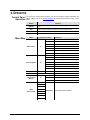
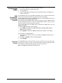
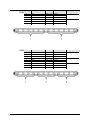
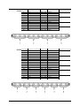
User Manual TABLE OF CONTENTS 1. Before You Begin ................................................................................. 3 What Is Included ............................................................................................... 3 Unpacking Instructions ...................................................................................... 3 Claims ........................................................................................................................ 3 Text Conventions .............................................................................................. 3 Icons .................................................................................................................. 3 Document Information ....................................................................................... 3 Product at a Glance .......................................................................................... 4 Safety Notes ...................................................................................................... 4 2. Introduction .......................................................................................... 5 Product Overview .............................................................................................. 5 Product Dimensions .......................................................................................... 6 3. Setup ..................................................................................................... 7 AC Power .......................................................................................................... 7 Fuse Replacement ..................................................................................................... 7 Power Linking............................................................................................................. 8 Mounting ........................................................................................................... 9 Orientation ................................................................................................................. 9 Rigging ....................................................................................................................... 9 4. Operation ............................................................................................ 10 Control Panel Operation.................................................................................. 10 Menu Map ....................................................................................................... 10 Configuration (DMX) ....................................................................................... 11 DMX Personalities and Starting Address ................................................................ 11 Sectional Control ...................................................................................................... 11 DMX Channel Assignments and Values ......................................................... 12 7-CH ......................................................................................................................... 12 3-CH ......................................................................................................................... 12 4-CH ......................................................................................................................... 12 6-CH ......................................................................................................................... 13 9-CH ......................................................................................................................... 13 12-CH ....................................................................................................................... 14 18-CH ....................................................................................................................... 14 36-CH ....................................................................................................................... 15 Configuration (Standalone) ............................................................................. 16 Static Color Mode..................................................................................................... 16 Automatic Mode ....................................................................................................... 16 Custom Static Color Mode ....................................................................................... 16 Master/Slave Mode .................................................................................................. 17 5. Technical Information........................................................................ 17 Product Maintenance ...................................................................................... 17 General Troubleshooting ................................................................................ 18 Contact Procedure .......................................................................................... 19 CHAUVET® Contact Information .................................................................... 19 Returning Products to CHAUVET® ................................................................ 19 6. Technical Specifications ................................................................... 20 Page 2 of 20 COLORband PiX™ User Manual (Rev. 02) 1. BEFORE YOU BEGIN What Is Included Unpacking Instructions Claims Text Conventions Icons • • • • • 1 x COLORband PiX™ 1 x Power Cord 2 x L-Brackets 1 x Warranty Card 1 x Quick Reference Guide Immediately upon receipt, carefully unpack the product and check the container to make sure you have received all the parts indicated above in good condition. If the container or the material inside the container (the product and included accessories) appear damaged from shipping, or show signs of mishandling, upon receipt notify the carrier immediately, not CHAUVET®. Failure to do so in a timely manner may invalidate your claim with the carrier. In addition, keep the container and all the packing material for inspection. For other issues such as missing components or parts, damage not related to shipping, or concealed damage, file a claim with CHAUVET® within seven (7) days of receiving the merchandise. Convention 1~512 50/60 Settings Menu > Settings <ENTER> ON Icon Meaning A range of values A set of values of which only one can be chosen A menu option not to be modified A sequence of menu options to be followed A key to be pressed on the product’s control panel A value to be entered or selected Meaning Critical installation, configuration, or operation information. Failure to comply with this information may render the product partially or completely inoperative, cause damage to the product, or cause harm to the user. Important installation or configuration information. Failure to comply with this information may prevent the product from functioning correctly. Useful non-critical information. Document Information The information and specifications contained in this document are subject to change without notice. CHAUVET® assumes no responsibility or liability for any errors or omissions that may appear in this manual. CHAUVET® reserves the right to update the existing document or to create a new document to correct any errors or omissions. You can download the latest version of this document from www.chauvetlighting.com. © Copyright 2012 CHAUVET®. All rights reserved Electronically published by CHAUVET® in the United States of America. Author Date Editor Date A. Diaz 1/12/12 S. Graham 1/12/12 COLORband PiX™ User Manual (Rev. 02) Page 3 of 20 Product at a Glance Use on Dimmer Outdoor Use Sound Activated DMX Master/Slave Safety Notes Auto Programs Auto-ranging Power Supply Replaceable Fuse User Serviceable Duty Cycle Please read the following Safety Notes carefully before working with the product. The Notes include important safety information about installation, usage, and maintenance. • • • • • • • • • • • • • • • • • • Always connect the product to a grounded circuit to avoid the risk of electrocution. Always disconnect the product from the power source before cleaning or replacing the fuse. Avoid direct eye exposure to the light source while the product is on. Make sure the power cord is not crimped or damaged. Never disconnect the product from power cord by pulling or tugging on the cord. If mounting the product overhead, always secure to a fastening device using a safety cable. Make sure there are no flammable materials close to the product during operation. Do not touch the product’s housing when operating because it may be very hot. Always make sure that the voltage of the outlet to which you are connecting the product is within the range stated on the decal or rear panel of the product. The product is for indoor use only! (IP20) To prevent risk of fire or shock, do not expose the product to rain or moisture. Always install the product in a location with adequate ventilation, at least 20 in (50 cm) from adjacent surfaces. Be sure that no ventilation slots on the product’s housing are blocked. Never connect the product to a dimmer. Make sure to replace the fuse with another of the same type and rating. Never carry the product from the power cord or any moving part. Always use the hanging/mounting bracket or the handles. The maximum ambient temperature (Ta) is 104° F (40° C). Do not operate the product at higher temperatures. In the event of a serious operating problem, stop using the product immediately. Never try to repair the product. Repairs carried out by unskilled people can lead to damage or malfunction. Please contact the nearest authorized technical assistance center. Keep this User Manual for future consultation. If you sell the product to another user, be sure that they also receive this document. Page 4 of 20 COLORband PiX™ User Manual (Rev. 02) 2. INTRODUCTION Product Overview U-Bracket (x2) Power Out Bracket Adjustment Knob Power In Microphone 3-pin DMX Connectors LED Display 5-pin DMX Connectors Sound Sensitivity Knob COLORband PiX™ User Manual (Rev. 02) Page 5 of 20 Product Dimensions Page 6 of 20 COLORband PiX™ User Manual (Rev. 02) 3. SETUP AC Power The COLORband PiX™ has an auto-ranging power supply and it can work with an input voltage range of 100~240 VAC, 50/60 Hz. To determine the product’s power requirements (circuit breaker, power outlet, and wiring), use the current value listed on the label affixed to the product’s back panel, or refer to the product’s specifications chart. The listed current rating indicates the product’s average current draw under normal conditions. Always connect the product to a protected circuit (circuit breaker or fuse). Make sure the product has an appropriate electrical ground to avoid the risk of electrocution or fire. Never connect the product to a rheostat (variable resistor) or dimmer circuit, even if the rheostat or dimmer channel serves only as a 0% to 100% switch. Fuse Replacement Follow the instructions below to change the fuse, if necessary. Disconnect the product from the power outlet before replacing the fuse. 1. 2. 3. 4. Wedge the tip of a flat-head screwdriver into the slot of the fuse holder. Pry the fuse holder out of the housing. Remove the blown fuse from the holder and replace with a fuse of the exact same type and rating. Insert the fuse holder back in place and reconnect power. Installed fuse (held by plastic clip) Safety cap Spare fuse holder (inside safety cap) The product does not ship with a spare fuse; however, the safety cap has room for a spare. COLORband PiX™ User Manual (Rev. 02) Page 7 of 20 Power Linking The product provides power linking via the IEC outlet located in the back of the unit. See the diagram below. Power Linking Diagram 1st Product 2nd Product 3rd Product Other products You can power link up to 11 COLORband PiX™ units on 120 VAC or up to 20 COLORband PiX™ units on 230 VAC. The power linking diagram shown above corresponds to the North American version of the product ONLY! If using the product in other markets, you must consult with the local CHAUVET® distributor as power linking connectors and requirements may differ in your country or region. Page 8 of 20 COLORband PiX™ User Manual (Rev. 02) Mounting Before mounting the product, read and follow the safety recommendations indicated in the Safety Notes. Orientation The COLORband PiX™ may be mounted in any position; however, make sure adequate ventilation is provided around the product. Rigging • Before deciding on a location for the product, always make sure there is easy access to the product for maintenance and programming purposes. • Make sure that the structure or surface onto which you are mounting the product can support the product’s weight. Please see the Technical Specifications section of this manual for weight information. • When mounting the product overhead, always use a safety cable. Mount the product securely to a rigging point, whether an elevated platform or a truss. • When rigging the product onto a truss, you should use a mounting clamp of appropriate weight capacity. The bracket has a 13-mm hole, which is appropriate for this purpose. • When power linking multiple products, you must always consider the length of the power linking cable and mount the products close enough for the cable to reach. • The bracket adjustment knobs allow for directional adjustment when aiming the product to the desired angle. Only loosen or tighten the bracket knobs manually. Using tools could damage the knobs. • The mounting brackets also serve as floor supports/allow for surface mounting. When mounting the product on the floor, make sure that the product and cables are away from people and vehicles. Mounting Diagram Mounting Bracket Bracket Adjustment Knob U-Bracket (x2) L-Bracket (x2) COLORband PiX™ User Manual (Rev. 02) Page 9 of 20 4. OPERATION Control Panel Operation To access the control panel functions, use the four buttons located underneath the display. Please refer to the Product Overview to see the button locations on the control panel. Button <MENU> <UP> Menu Map Function Press to find an operation mode or to back out of the current menu option Press to scroll up the list of options or to find a higher value <DOWN> Press to scroll down the list of options or to find a lower value <ENTER> Press to activate a menu option or a selected value Mode Static Colors Auto Programs Program Speed Programming Steps C-- P-- S-- Slave Mode Custom Color Mixing C1 Red C2 Green C3 Blue C4 Cyan C5 Magenta C6 Yellow C7 White P1 7-Color Switching P2 7-Color Fading P3 3-Color Switching P4 3-Color Fading P5 Chase Program P6 7-Color Sound Active P7 7-Color Sound Active Chase + Strobe S001-S100 SLA U-- Description Selects auto program speed Sets Slave Mode r-- Red g-- Green b-- Blue 3-CH 4-CH 6-CH DMX Personalities 7-CH 9-CH d001-d512 Selects DMX starting address 12-CH 18-CH 36-CH Page 10 of 20 COLORband PiX™ User Manual (Rev. 02) Configuration (DMX) DMX Personalities and Starting Address Set the product in DMX mode to control with a DMX controller. 1. Connect the product to a suitable power outlet. 2. Turn the product on. 3. Connect a DMX cable from the DMX output of the DMX controller to the DMX input socket on the product. The COLORband PiX™ has eight DMX personalities, from a 3-channel mode for basic control to a 36-channel mode with more advanced control over the lights. The COLORband PiX™ uses up to 36 DMX channels in its 36-channel DMX mode, which defines the highest configurable address to 477. When selecting a starting DMX address, always consider the number of DMX channels the selected DMX mode uses. If you choose a starting address that is too high, you could restrict the access to some of the product’s channels. If you are not familiar with the DMX protocol, download the “DMX Primer” from the CHAUVET® website. To select the DMX personality, do the following: 1. Press <MENU> repeatedly until 3-CH, 4-CH, 6-CH, 7-CH, 9-CH, 12CH, 18CH, or 36CH shows on the display. 2. Press <ENTER> to choose your DMX personality when it appears on the display. To then choose your starting address: 1. The display should show d 1 once you’ve selected your DMX personality using the steps above. 2. Use <UP> or <DOWN> to select the starting address. 3. Press <ENTER>. Sectional Control The COLORband PiX™ offers by-section control of the lights, and you can select from two through 12 sections to control. To access this feature, choose the DMX personality as shown above. What each DMX personality controls is shown below. Note: not all DMX personalities offer sectional control. COLORband PiX™ User Manual (Rev. 02) Page 11 of 20 DMX Channel Assignments and Values 7-CH Channel Function Red 000 255 0~100% 2 Green 000 255 0~100% 3 Blue 4 Color Macros 000 255 0~100% 000 015 No function 016 255 Color Macros Speed (slow to fast) 000 255 (when CH.6 is from 032~233) 000 015 No function 016 255 0~30 Hz 000 031 No function 032 063 Pulse effect 0%~100% 064 095 Pulse effect 100%~0% 096 114 Pulse effect 100%~0%~100% 115 127 Chase program 128 159 Auto fade transition 160 191 Auto snap transition (3 colors) 192 223 Auto snap transition (7 colors) 224 255 Sound active mode 000 255 0~100% Speed 4-CH Page 12 of 20 Setting 1 5 3-CH Value Strobe (CH.1-CH.4 only) 6 Auto Programs 7 Dimmer Channel Function Value Setting 1 Red 000 255 0~100% 2 Green 000 255 0~100% 3 Blue 000 255 0~100% Channel Function Value Setting 1 Red 000 255 0~100% 2 Green 000 255 0~100% 3 4 Blue Dimmer 000 255 0~100% 000 255 0~100% COLORband PiX™ User Manual (Rev. 02) 6-CH 9-CH Channel Function Value Setting 1 Red 000 255 0~100% 2 Green 000 255 0~100% 3 Blue 000 255 0~100% 4 5 6 Red Green Blue 000 255 0~100% 000 255 0~100% 000 255 0~100% Channel Function Value Setting Section 1 2 Section 1 Red 000 255 0~100% 2 Green 000 255 0~100% 3 Blue 000 255 0~100% 4 5 6 Red Green Blue 000 255 0~100% 000 255 0~100% 000 255 0~100% 2 7 8 9 Red Green Blue 000 255 0~100% 000 255 0~100% 000 255 0~100% 3 COLORband PiX™ User Manual (Rev. 02) 1 Page 13 of 20 12-CH 18-CH Page 14 of 20 Channel Function Value Setting Section 1 Red 000 255 0~100% 2 Green 000 255 0~100% 3 Blue 000 255 0~100% 4 5 6 Red Green Blue 000 255 0~100% 000 255 0~100% 000 255 0~100% 2 7 8 9 Red Green Blue 000 255 0~100% 000 255 0~100% 000 255 0~100% 3 10 11 12 Red Green Blue 000 255 0~100% 000 255 0~100% 000 255 0~100% 4 Channel Function Value Setting 1 Section 1 Red 000 255 0~100% 2 Green 000 255 0~100% 3 Blue 000 255 0~100% 4 5 6 Red Green Blue 000 255 0~100% 000 255 0~100% 000 255 0~100% 2 7 8 9 Red Green Blue 000 255 0~100% 000 255 0~100% 000 255 0~100% 3 10 11 12 Red Green Blue 000 255 0~100% 000 255 0~100% 000 255 0~100% 4 13 14 15 Red Green Blue 000 255 0~100% 000 255 0~100% 000 255 0~100% 5 16 17 18 Red Green Blue 000 255 0~100% 000 255 0~100% 000 255 0~100% 6 1 COLORband PiX™ User Manual (Rev. 02) 36-CH Channel Function Value Setting Section 1 Red 000 255 0~100% 2 Green 000 255 0~100% 3 Blue 000 255 0~100% 4 5 6 Red Green Blue 000 255 0~100% 000 255 0~100% 000 255 0~100% 2 7 8 9 Red Green Blue 000 255 0~100% 000 255 0~100% 000 255 0~100% 3 10 11 12 Red Green Blue 000 255 0~100% 000 255 0~100% 000 255 0~100% 4 13 14 15 Red Green Blue 000 255 0~100% 000 255 0~100% 000 255 0~100% 5 16 17 18 Red Green Blue 000 255 0~100% 000 255 0~100% 000 255 0~100% 6 19 20 21 Red Green Blue 000 255 0~100% 000 255 0~100% 000 255 0~100% 7 22 23 24 Red Green Blue 000 255 0~100% 000 255 0~100% 000 255 0~100% 8 25 26 27 Red Green Blue 000 255 0~100% 000 255 0~100% 000 255 0~100% 9 28 29 30 Red Green Blue 000 255 0~100% 000 255 0~100% 000 255 0~100% 10 31 32 33 Red Green Blue 000 255 0~100% 000 255 0~100% 000 255 0~100% 11 34 35 36 Red Green Blue 000 255 0~100% 000 255 0~100% 000 255 0~100% 12 COLORband PiX™ User Manual (Rev. 02) 1 Page 15 of 20 Configuration (Standalone) Set the product in one of the standalone modes to control without a DMX controller. 1. Connect the product to a suitable power outlet. 2. Turn the product on. Never connect a product that is operating in any standalone mode (either Static, Automatic, or Sound) to a DMX string connected to a DMX controller. Products in standalone mode may transmit DMX signals that could interfere with the DMX signals from the controller. Static Color Mode Automatic Mode To enable the Static Color Mode, do the following: 1. Press <MENU> repeatedly until C-- shows on the display. 2. Press <ENTER>. 3. Use <UP> or <DOWN> to choose a color (C1-C7). 4. Press <ENTER>. To enable the Automatic Mode, follow the instructions below: 1. Press <MENU> repeatedly until P-- shows on the display. 2. Press <ENTER>. 3. Use <UP> or <DOWN> to choose your auto program (P1-P7). 4. Press <ENTER>. You can adjust the speed of the automatic program as well. 1. Press <MENU> repeatedly until S-- shows on the display. 2. Press <ENTER>. 3. Use <UP> or <DOWN> to adjust the duration of each step of the automatic program from S001 (slow) to S100 (fast). 4. Press <ENTER>. Custom Static Color Mode Page 16 of 20 To enable the Custom Static Color Mode, follow the instructions below: 1. Press <MENU> repeatedly until U-- shows on the display. 2. Press <ENTER>. 3. Press <UP> or <DOWN> to choose between colors (r--, g--, b--). 4. Press <ENTER>. 5. Press <UP> or <DOWN> to choose the intensity of the color (000-100). 6. Repeat the steps to mix additional colors to create the color you need. 7. Press <ENTER>. COLORband PiX™ User Manual (Rev. 02) Master/Slave Mode The Master/Slave mode allows a single COLORband PiX™ unit (the “master”) to control the actions of one or more COLORband PiX™ units (the “slaves”) without the need of a DMX controller. The master unit will be set to operate in either Automatic or Sound Active mode, while the slave units will be set to operate in Slave Mode. Once set and connected, the slave units will operate in unison with the master unit. Configure the units as indicated below. Slave units: 1. Press <MENU> repeatedly until SLA shows on the display. 2. Press <ENTER> to accept. 3. Set the DMX address to 001. 4. Connect the DMX input of the first slave unit to the DMX output of the master unit. 5. Connect the DMX input of the subsequent slave units to the DMX output of the previous slave unit. 6. Finish setting and connecting all the slave units. Master unit: 1. Set the master unit to operate in either Automatic or Sound Active mode. 2. Make the master unit the first unit in the DMX daisy chain. • Configure all the slave units before connecting the master unit to the DMX daisy chain. • Never connect a DMX controller to a DMX string configured for Master/Slave operation because the controller may interfere with the signals from the master unit. • Do not connect more than 31 slave units to the master unit. 5. TECHNICAL INFORMATION Product Maintenance Dust build-up reduces light output performance and can cause overheating. This can lead to reduction of the light source’s life. To maintain optimum performance and minimize wear, you should clean your lighting products at least twice a month. However, be aware that usage and environmental conditions are contributing factors to increasing the cleaning frequency. To clean the product, follow the instructions below: • Unplug the product from power. • Wait until the product is cold. • Use a vacuum (or dry compressed air) and a soft brush to remove dust collected on the external surface/vents. • Clean all transparent surfaces with a mild soap solution, ammonia-free glass cleaner, or isopropyl alcohol. • Apply the solution directly to a soft, lint-free cotton cloth or a lens cleaning tissue. • Softly drag any dirt or grime to the outside of the transparent surface. • Gently polish the transparent surfaces until they are free of haze and lint. Always dry the transparent surfaces carefully after cleaning them. COLORband PiX™ User Manual (Rev. 02) Page 17 of 20 General Troubleshooting Symptom Possible Cause Excessive load on the circuit Make sure that the total load does not exceed 80% of the breaker or fuse nominal current Short circuit along the power lines Check the power lines and power cords No energy on power outlet Check power outlet Change to another outlet Loose or damaged power cord Check the power cord Blown fuse Replace blown fuse with a good one of the same type and rating Internal problem Send product for repair Wrong starting address on the product Set the correct starting address on the product Use the right fader(s) on the controller Wrong DMX personality on the product Set the correct DMX product’s personality Assign the faders accordingly Wrong polarity setting on the DMX controller Change the signal polarity on the controller Loose or damaged DMX cable Check the DMX cable before the faulty unit Internal problem Send product for repair Signal cables are not DMX compatible Replace non-DMX cables with true DMX cables Interference with AC or radio signals Keep DMX cables away from AC wires or radio equipment DMX cable too long Install an optically coupled DMX amplifier right before the product with intermittent problems Too many products connected Install an optically coupled DMX amplifier after unit #32 Terminator not connected Install a terminator, as indicated in the DMX Primer Circuit breaker or fuse keeps blowing Product does not power up Product does not respond to DMX Intermittent DMX Problems Possible Action If you still experience problems after trying the above solutions, contact CHAUVET® Technical Support. Page 18 of 20 COLORband PiX™ User Manual (Rev. 02) Contact Procedure CHAUVET® Contact Information In case you need to return a product or request support, follow the procedure below: • • • If you live in the U.S., contact CHAUVET® World Headquarters (see below). If you live in the UK or Ireland, contact CHAUVET® Europe Ltd. (see below). If you live in any other country, DO NOT contact CHAUVET®. Instead, contact your distributor of record. Refer to our website for contact details of distributors outside the U.S., United Kingdom, or Ireland. World Headquarters CHAUVET® General Information Address: 5200 NW 108th Avenue Sunrise, FL 33351 Voice: (954) 929-1115 Fax: (954) 929-5560 Toll free: (800) 762-1084 Technical Support Voice: (954) 929-1115 (Press 4) Fax: (954) 756-8015 Email: [email protected] World Wide Web www.chauvetlighting.com United Kingdom & Ireland CHAUVET® Europe Ltd. General Information Address: Unit 1C Brookhill Road Industrial Estate Pinxton, Nottingham, UK NG16 6NT Voice: +44 (0)1773 511115 Fax: +44 (0)1773 511110 Technical Support Email: [email protected] World Wide Web www.chauvetlighting.co.uk If you live outside the U.S., United Kingdom, or Ireland, contact your distributor of record and follow their instructions on how to return CHAUVET® products to them. Visit our website for contact details. Returning Products to CHAUVET® Call the corresponding CHAUVET® Tech Support office and request a Return Merchandise Authorization (RMA) number before shipping the product. Be prepared to provide the model number, serial number, and a brief description of the cause for the return. You must send the merchandise prepaid, in its original box, and with its original packing and accessories. CHAUVET® will not issue call tags. Clearly label the package with the RMA number. CHAUVET® will refuse any product returned without an RMA number. Write the RMA number on a properly affixed label. DO NOT write the RMA number directly on the box. Before sending the product, clearly write the following information on a piece of paper and place it inside the box: • Your name • Your address • Your phone number • The RMA number • A brief description of the problem Be sure to pack the product properly. Any shipping damage resulting from inadequate packaging will be your responsibility. As a suggestion, proper FedEx packing or doubleboxing are recommended shipping methods. CHAUVET® reserves the right to use its own discretion to repair or replace returned product(s). COLORband PiX™ User Manual (Rev. 02) Page 19 of 20 6. TECHNICAL SPECIFICATIONS Dimensions and Weight Length Width Height Weight 41.6 in (1,057 mm) 6.1 in (154 mm) 2.5 in (64 mm) 8.9 lbs (4 kg) Note: Dimensions in inches rounded to the nearest decimal digit. Power Light Source Photo Optic Thermal DMX Ordering Page 20 of 20 Power Supply Type Range Voltage Selection Switching (internal) 100~240 V, 50/60 Hz Auto-ranging Parameter 120 V, 60 Hz 230 V, 50 Hz Consumption 82 W 86 W Operating 0.7 A 0.4 A Power linking current (units) 8 A (11 units) 8 A (20 units) Fuse F 2 A, 250 V F 2 A, 250 V Power I/O US/Worldwide UK/Europe Power input connector IEC IEC Power output connector Edison IEC Power Cord plug Edison (U.S.) Local plug Type Power Lifespan LED 3W 50,000 hours Color Quantity Current Tri-color 12 350 mA Parameter Strobe Rate 0-30 Hz Illuminance @ 2 m 1,947 lux Beam angle 19º Field angle 35° Maximum External Temp. Cooling System 104° F (40° C) Convection I/O Connectors Connector Type Channel Range 3-pin and 5-pin XLR Sockets 3, 4, 6, 7, 9, 12, 18, 36 Product Name Item Code Item Number COLORband PiX™ 03020469 COLORBANDPIX COLORband PiX™ User Manual (Rev. 02)