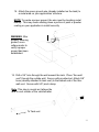
1
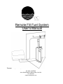
Remote Fill Fuel System User’s Manual *Illustration may not be representative. ECI FUEL SYSTEMS 3281 GRAPEVINE ST MIRA LOMA, CA 91752 877.685.8602 www.ecifuelsystems.com ! PLEASE READ BEFORE INSTALLING SYSTEM! ! Certain components including, without limita5on, fuel tanks, pumps, control panels, moun5ng hardware may be developed by ECI Fuel Systems. It is crucial that purchaser test these products in their specific applica5on to determine appropriateness. The installa5on and opera5on of these components is the sole responsibility of the original purchaser. Not all generators and engines are emissions compa5ble with ECI fuel systems. To ensure EPA or CARB compliance contact ECI Fuel Systems before pairing your engine or generator with an ECI fuel system. ECI Fuel Systems will not be responsible for the misuse of this product, failure of the original purchaser to service this product or use of this product in a manner inconsistent with its intended purpose COULD RESULT IN FIRE, EXPLOSION, SERIOUS INJURY, OR DEATH. ECI FUEL SYSTEMS 3281 GRAPEVINE ST MIRA LOMA, CA 91752 877.685.8602 www.ecifuelsystems.com 2 BEFORE YOU BEGIN… User’s Manual Before beginning installation of your ECI fuel system please refer to regulations of any organization you may be building to. Study and understand this user’s manual. Important information and helpful tips will make your installation easier. Fuel System ECI Fuel Systems builds and certifies all tanks and fuel systems to NFPA 1192 standards. To Ensure the ECI fuel system you have purchased is installed per NFPA 1192 regulations, please follow the NFPA regulations at www.nfpa.org. ECI has certified all of its fuel systems with the California Air Resources Board (CARB) and the Environmental Protection Agency (EPA) when applicable. Any unauthorized modification to the fuel system will void CARB and EPA certifications and the end user will be responsible for any fines put forward by said agencies. Failure to ensure that the ECI fuel system purchased has been certified with the motor and/or generator which it will be connected to could result in fines form both CARB & EPA. These fines are the responsibility of the end user. If there is any question of the compatibility, please call ECI. ECI’s fuel systems are not meant to be used with unleaded gasoline with more than 15% ethanol blend or biodiesel blends in excess of B-20. Parts and Parts List Check to be sure that you have all the necessary parts for your fuel system. • All part numbers can be found on the parts list on page 8 (gasoline parts) and page 17 (diesel parts) of this users manual. Please have the following information ready when contacting ECI for parts: • Fuel system P/N • Where it was purchased • Date of purchase 3 Plan Ahead… Tools and Materials Some basic tools you will need for the installation of your fuel system: • Safety glasses • Work gloves • Phillips head screw driver • Crescent Wrench • Pincer Tool (To Close Pinch Clamp) • Tape measure • Level • Power Drill (optional) Installation Area Before installing, you must choose an area on your equipment that will be suited to hold a fuel tank. Confirm you have the structure needed to support your tank, including the fuel that will be added (gasoline ≈ 6.073 lbs/gal, diesel ≈ 7.15 lbs/gal). Acceptable areas for installation per NFPA 1192 would be: • Under the floor / inside main rail • In a compartment: • Compartment shall be vapor resistant to vehicle/trailer interior • Compartment shall not contain flame- or spark producing equipment • Compartment must have floors and walls resistant and nonabsorbent to fuel. Floor has a minimum of 1/2” diameter drainage hole to the exterior at each low point • On a trailer A-frame • No part should extend below the bottom of the A-frame members • Forward of the front bulkhead below the overhang of a fifthwheel 4 Safety First… Safety precautions are important to follow throughout the installation of your fuel system. Care must be taken when handling various pieces of your fuel system. Please wear work gloves, safety goggles or glasses, and long sleeves when installing or performing any maintenance. Practice caution with tools being used during installation. Be familiar with the operation of all power tools being used. Never drill or weld on or near tank. Do not attempt to install the fuel system if parts are missing. Any partial installation may result in damage or injury and void warranty. Do not put fuel into tank until install is completely finished. Fuel may spill causing hazardous conditions during your installation. Do no smoke around installation area. 5 User Manual Navigation There are two sections to this guide: gasoline and diesel. Please navigate to the section that applies to your system: Section 1.....Gasoline…..P. 7 Section 2…..Diesel…..P. 19 6 SECTION 1 Gasoline 7 Items Needed for Gasoline Installation… Fuel Tank Qty: 1 #5761 Fill Neck QTY: 1 #1109 1.5” x 24” Fuel Hose QTY: 1 5/16” Pinch Clamp QTY: 3 #5439 45° Bezel w/ Gas Cap QTY: 1 #1501 1/2” Screw Clamp QTY: 2 #3357 1/4" Pinch Clamp (Blue) (14.0) QTY: 1 #1506 1.5” Screw Clamp QTY: 2 #1101 1/2” x 24” Fuel Hose QTY: 1 8 Items Needed for Gasoline Installation… #3302 1/4” 30R14 Fuel Hose (Installed) QTY: 10FT #0113 3/8” Washer Grade 5 QTY: 4 #3355 5/8" Pinch Clamp (25.6) QTY: 1 #3303 5/16” 30R14 Fuel Hose (Installed) QTY: 10FT #0125 7/16” Nylon Lock Nut Grade 5 QTY: 2 #5467 Carbon Canister w/ Bracket QTY: 1 #0123 7/16” x 1-1/2” Grade 5 Bolt QTY: 2 #0560 Thru Wall Vent QTY: 1 #5292 Canister Extension Bracket 9 QTY: 1 Items Needed for Gasoline Installation… #5831 Floor Bracket Qty: 1 #5859 Bolt Cover QTY: 1 #5858 Hold Down Brackets QTY: 2 10 1. Place the floor bracket flush to the floor and secure with grade 5 bolts, nuts, and washers (not included). To secure floor bracket properly, 1 bolt in each corner (circled) must be secured. 2. After securing floor bracket, place bolt over over bolts. 3. Slide tank over the angle on the floor bracket to secure the bracket to the tank. 4. Install the two angles (#5858) with provided hardware to secure the tank to the floor. 11 5. Bolt the hold down brackets with the hardware provided into the hole just drilled in the flooring surface. Note: All bolts and nuts are grade 5. Only use the bolts, nuts and washers provided. If a longer bolt is required, use only grade 5 bolts. 0123 5690 0113 0113 0125 6. Hold down bracket should now be holding the tank securely to the flooring surface. Repeat this with additional brackets until tank is securely tightened to the flooring surface. 12 7. Find the desired position for the bezel/cap assembly on the exterior wall of your trailer/vehicle. Drill a 5” diameter hole through the wall. Square up the bezel with the rivet being positioned on top. Secure the bezel with screws. *Note: If there is not a solid wall to attach the bezel to, a bezel backing bracket is available for purchase (P/N – 6466 or 6433) 8. Install 1.5” fuel hose onto tank. This hose should be cut to length depending on the desired height and placement of bezel. Secure with 1.5” screw clamp. 9. Repeat step “8” with .5” fuel hose. 13 10. Install the fill neck on the 1.5” hose and .5” hose, respectively. Adjust the fill neck so the mounting ring meets the back side of the bezel. Screw the bezel to the mounting ring of the fill neck from the front side with the two holes provided. 11. Tighten 1.5” screw clamp and .5” screw clamp around hoses installed on fill neck. *Shown w/ optional backing plate 12. Use a gasoline compatible silicon to seal the area where the bezel meets the fill neck mounting ring. This will help prevent gasoline from leaking into the interior of the trailer while fueling. ! Warning: Gasoline fumes can be harmful or cause death if breathed in. Following this step will help prevent gasoline fumes from entering the interior of your application. 14 13. Carbon Canister Installation Locate a secure surface (ibeam, cross-member, clear wall, etc.) to install carbon canister extension bracket. Once the canister extension bracket has been secured, place the carbon canister w/ bracket (#5467) over the bolts on the extension bracket. Tighten the nuts already installed on the bracket to secure the canister. NOTE: DO NOT INSTALL CARBON CANISTER WITH PORTS FACING DOWN. THIS WILL CAUSE THE CANISTER TO MALFUNCTION! 15 14. Canister hose installation. a) To rollover valve (ROV) (already installed on canister side); b) 5/16” to generator vapor port (see page 17) c) 5/8” hose (installed). Line reserved for fresh air. a b c NOTE: Secure all canister hoses with 5/16” pinch clamp (P/N 3351 – 15.3) ROV ON TANK 16 Gasoline System Hose Connection Evap. Fuel 15. 10FT of 1/4” 30R14 hose line will already be installed on the tank. This is the fuel line and it attaches to the port on the generator/engine intended for fuel. Please consult your generator/engine manual to confirm location of fuel port. Secure this line with the blue pinch clamp marked “14.0” (P/ N 3357). 16. 10FT of 5/16” 30R14 hose line was installed on the center port of the carbon canister. This is the vapor line and it attaches to the port on the generator. Please consult your generator/engine manual to confirm location of vapor port. Secure this line with the silver pinch clamp marked “15.3” (P/N 3351) ! ! Note: All fuel and vapor line for gasoline systems are SAE J30R14 rated. At no point should this hose be replaced with any other type of hose or risk voiding warranty and/or becoming non-compliant. If more hose is desired, more can be ordered from your fuel system distributor. Note: Only pinch clamps may be used for the connections on the fuel and vapor line. Do not use any other type of connection or risk voided warranty. 17 17. Attach the green ground wire (already installed on the tank) to a metal area on your applications’ structure. NOTE: To create a proper ground, the wire must be touching metal directly. This may mean sanding down a portion of paint or powder coating on your application to install correctly. WARNING: After properly securing ground, use a voltage meter to verify a proper ground has been established. 18. Drill a 3/4” hole through the wall nearest the tank. Place “thru-wall vent” through the outside wall. Secure with provided nut. Attach 5/8” hose (already attached to carbon canister) to the barbed end of the thru-wall vent. Secure with 5/8” pinch clamp. Note: This step is crucial as it allows the canister to draw fresh air and vent to the outside of the vehicle/trailer. To Canister 18 SECTION 2 Diesel 19 Items Needed for Diesel Installation… Fuel Tank Qty: 1 #5762 Fill Neck QTY: 1 #1109 1.5” x 24” Fuel Hose QTY: 1 5/16” Pinch Clamp QTY: 2 #5439 45° Bezel w/ Gas Cap QTY: 1 #1501 1/2” Screw Clamp QTY: 2 #3357 1/4" Pinch Clamp (Blue) (14.0) QTY: 2 #1506 1.5” Screw Clamp QTY: 2 #1101 1/2” x 24” Fuel Hose QTY: 1 20 Items Needed for Diesel Installation… #3302 1/4” 30R14 Fuel Hose (Installed) QTY: 10FT #0113 3/8” Washer Grade 5 QTY: 4 #3355 5/8" Pinch Clamp (25.6) QTY: 1 #3303 5/16” 30R14 Fuel Hose (Installed) QTY: 10FT #0125 7/16” Nylon Lock Nut Grade 5 QTY: 2 #5831 Floor Bracket Qty: 1 #0123 7/16” x 1-1/2” Grade 5 Bolt QTY: 2 #0560 Thru Wall Vent QTY: 1 #5859 Bolt Cover QTY: 1 21 Items Needed for Diesel Installation… #5858 Hold Down Brackets QTY: 2 22 1. Place the floor bracket flush to the floor and secure with grade 5 bolts, nuts, and washers (not included). To secure floor bracket properly, 1 bolt in each corner (circled) must be secured. 2. After securing floor bracket, place bolt over over bolts. 3. Slide tank over the angle on the floor bracket to secure the bracket to the tank. 4. Install the two angles (#5858) with provided hardware to secure the tank to the floor. 23 5. Bolt the hold down brackets with the hardware provided into the hole just drilled in the flooring surface. Note: All bolts and nuts are grade 5. Only use the bolts, nuts and washers provided. If a longer bolt is required, use only grade 5 bolts. 0123 5690 0113 0113 0125 6. Hold down bracket should now be holding the tank securely to the flooring surface. Repeat this with additional brackets until tank is securely tightened to the flooring surface. 24 7. Find the desired position for the bezel/cap assembly on the exterior wall of your trailer/vehicle. Drill a 5” diameter hole through the wall. Square up the bezel with the rivet being positioned on top. Secure the bezel with screws. *Note: If there is not a solid wall to attach the bezel to, a bezel backing bracket is available for purchase (P/ N – 6466 or 6433) 8. Install 1.5” fuel hose onto tank. This hose should be cut to length depending on the desired height and placement of bezel. Secure with 1.5” screw clamp. 9. Repeat step “7” with .5” fuel hose. 25 10. Install the fill neck on the 1.5” hose and .5” hose, respectively. Adjust the fill neck so the mounting ring meets the back side of the bezel. Screw the bezel to the mounting ring of the fill neck from the front side with the two holes provided. 11. Tighten 1.5” screw clamp and .5” screw clamp around hoses installed on fill neck. *Shown w/ optional backing plate 12. Use a gasoline compatible silicon to seal the area where the bezel meets the fill neck mounting ring. This will help prevent gasoline from leaking into the interior of the trailer while fueling. ! Warning: Gasoline fumes can be harmful or cause death if breathed in. Following this step will help prevent gasoline fumes from entering the interior of your application. 26 Diesel System Hose Connection Return Withdrawal 12. 10FT of 1/4” 30R9 hose line will already be installed on the tank. This is the fuel line and it attaches to the port on the generator/engine intended for the withdrawal fuel. Please consult your generator/engine manual to confirm location of fuel port. Secure this line with the blue pinch clamp marked “14.0” (P/N 3357). 13. 10FT of 5/16” 30R9 hose line will already be installed on the tank. This is the return fuel line and it attaches to the port on the generator/engine intended for fuel return. Please consult your generator/engine manual to confirm location of return fuel line port. Secure this line with the silver pinch clamp marked “15.3” (P/N 3351) ! ! Note: All fuel line for diesel systems are SAE J30R9 rated. At no point should this hose be replaced with any other type of hose or risk voiding warranty and/or becoming non-compliant. If more hose is desired, more can be ordered from your fuel system distributor. Note: Only pinch clamps may be used for the connections on the fuel and vapor line. Do not use any other type of connection or risk voided warranty. 27 14. Attach the green ground wire (already installed on the tank) to a metal area on your applications’ structure. NOTE: To create a proper ground, the wire must be touching metal directly. This may mean sanding down a portion of paint or powder coating on your application to install correctly. WARNING: After properly securing ground, use a voltage meter to verify a proper ground has been established. 15. Drill a 3/4” hole through the wall nearest the tank. Place “thru-wall vent” through the outside wall. Secure with provided nut. Attach 5/8” hose (already attached to tank vent) to the barbed end of the thruwall vent. Secure with 5/8” pinch clamp. Note: This step is crucial as it allows the tank to vent outside of the vehicle/trailer. To Tank vent 28 Limited Warranty Policy ECI Fuel Systems Inc. (“ECI”) 3281 Grapevine Street, Mira Loma California 91752 provides this limited warranty against defects in material and workmanship on all products manufactured by ECI. ECI fuel systems include a 2-‐year warranty from date of purchase as evidenced by the original sales receipt. ECI's sole obliga5on under this limited warranty will be limited, at ECI’s op5on to either (i) replacing or repairing defec5ve goods (subject to limita5ons hereinader provided), or (ii) refunding the purchase price for such goods theretofore paid by the purchaser, and purchaser’s exclusive remedy for breach of any such warran5es will be enforcement of such obliga5ons of ECI. This limited warranty extends only to the ECI fuel system manufactured by ECI and any claims shall be limited to the purchase price paid for the ECI fuel system. This limited warranty shall extend to the purchaser and to any person to whom such product is transferred during the 2-‐year warranty period. This limited warranty shall not apply if (i) the product has been altered or modified, (ii) the product has been subjected to neglect, misuse, abuse or damage, or (iii) the product has been installed or operated other than in accordance with ECI’s opera5ng instruc5ons. To make a claim against this warranty, contact either the manufacture of the product, which the ECI fuel system is installed on or contact the distributor where the ECI fuel system purchased. ECI’S LIMITED WARRANTY EXCLUDES LIABILITY FOR DIRECT, INDIRECT, INCIDENTAL AND CONSEQUENTIAL DAMAGES INCURRED IN THE USE OR LOSS OF USE OF THE PRODUCT WARRANTED HEREUNDER. ECI expressly disclaims any warranty of merchantability or fitness for any par5cular purpose other than for which it was designed. This limited warranty gives you specific rights and you may also have other rights, which vary from U.S. state to U.S. state. ECI FUEL SYSTEMS 3281 GRAPEVINE ST MIRA LOMA, CA 91752 877.685.8602 www.ecifuelsystems.com