1
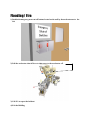
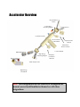
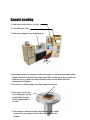
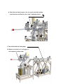
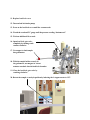
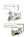
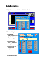
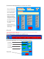
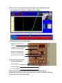
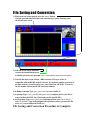
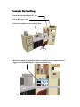
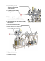
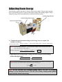
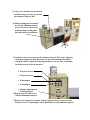
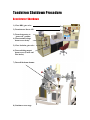
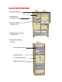
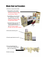
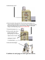
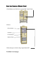
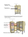
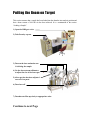
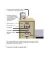
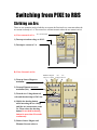
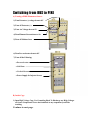
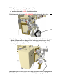
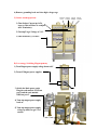
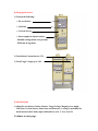
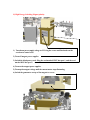
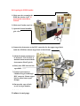
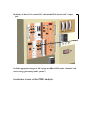
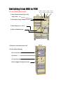
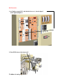
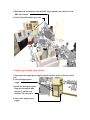
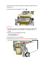
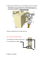
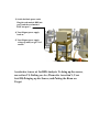
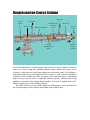
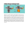
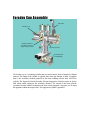
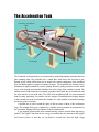
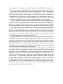
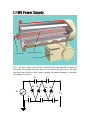
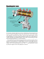
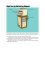
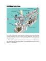
IBeAM Ion Beam Analysis of Materials Facility User Manual 1998 Mike Johnson Barry Wilkens Radiation Safety Precautions Extensive efforts have been made to reduce the radiation produced by the Tandetron to far below accepted non-occupational levels. It is possible, however, under fault conditions or with beams other than those for which a specific maximum radiation level has been guaranteed to produce potentially hazardous ionizing radiation. It is the responsibility of the operator of this instrument to have available at all times an operating and calibrated radiation detector sensitive to X-rays or gamma rays from 20 keV to several MeV. If ions other than those for which a specific radiation level has been guaranteed, are used in the Tandetron analyzer, nuclear reactions may occur which will produce neutrons or other forms of ionizing radiation under normal operating conditions. It is the responsibility of the user to attend a radiation safety seminar provided through the Office of Radiation Protection at Arizona State University, and wear a radiation film badge issued through that office at all time while in the accelerator facility. For radiation safety seminar times and scheduling please call 965-6140. High Voltage Electrical circuitry in the Tandetron is designed to shield and interlock against exposure of personnel to dangerous voltages. There are however, LETHAL voltages present in various parts of the Tandetron Analyzer which make it essential for the user to stay within designated areas and use caution when operating the equipment. Do not touch any equipment you have not been trained and authorized to use. The obvious area of High Voltage, is in the source area. Never poke anything through the cage. Never put anything over the cage and never try to bypass the cage interlock system. A less obvious high voltage hazard is the electrical connections on the ionization gauges, which measure the vacuum inside the beamline. Always use caution when handling the ionization gauges. Gas The sulfur hexaflouride insulating gas, sealed within the high pressure tank, is colorless, odorless, and heavier than air. While it is non-toxic, it will not support respiration. Adequate ventilation has been provided but in the event of a failure, exit the building and call the emergency number. Interlocks have been provided to reduce the probability of an accident. Attempts to defeat the interlocks put the user in personal danger. Section I Emergency Procedures Power Failure (Accidental System Vent) Flooding/Fire Loss of Sample in Vacuum Chamber Power Failure (Accidental System Vent) If electrical power to the accelerator should fail or dip, you will hear a lot of hissing and clanking. This is the sound of all the safety valves on the turbo pumps closing down the gate valves. Act quickly but calmly. 1) Turn Detector Bias to 10 Volts 2)Close RBS gate valve 3) Close Isolation Gate Valve 4) Push “Accelerator” Button Off (Out is Off) 5) Push “Injector” Power Button off WARNING! If you weren’t able to perform the above steps within 3-5 minutes of power failure, Stop at step 5 and call Barry or Bob. If enough time has elapsed, the three main turbos will have wound down and quickly opened the gate valves with the accelerator still under vacuum. This will cause backstreaming of oil into the vacuum system or possibly worse. Another scenario would be that the turbos could be spinning when you open the gate valves to a vented accelerator at atmosphere. This would flex the turbo’s rotor into its stators and destroy the pump. Each turbo pump is approximately $12,000.00! Be careful! 6) Continue to next page.... 7) Push “Vacuum Bypass” on (in) you will now hear clanking as the gate valves open. 8) If there are one or more interlock lights on, you will have to allow vacuum to recover before high voltage and sources can be turned on (The Turbo pumps may have to be restarted). This is a good time to contact Barry or Bob if you haven’t done so already. 9) Leave a note on operators console as to what has happened. Do not try to restart the source or turn up the High Voltage. 10) If the power failure was more than a “glitch”, the computer will reboot causing you to lose any un-saved files. Phone Numbers : Barry Wilkens Office: 965-9613 Home: 661-9874 Bob Culbertson Office: 965-0945 Home: 968-5992 Flooding/ Fire 1) Push both emergency power cut-off buttons located on the wall by the north entrance to the lab. 2) Pull the accelerator shut off lever to shut power to the accelerator off. 3) Call 911 to report the incident. 4) Exit the Building. Loosing a Sample in the Vacuum Chamber If you drop your sample inside the analysis chamber, call Barry to retrieve the sample. Use another sample holder in the mean time to continue with your analysis. Do not try to retrieve a sample without Barry present. If the analysis chamber is vented, the Ion pump must be restarted; a rather tricky and time consuming operation. Section II Facility Overview Operational Summary Accelerator Overview RBS Theory Operational Summary The lab consists of a 1.7 million volt tandem electrostatic accelerator with two beamlines and sample analysis end stations. Everything is done in vacuum with the exception of the External PIXE line. Typically accelerators are used for studies in nuclear physics, however since the mid 70’s they have increasingly come to be used for chemical analysis of materials using a variety of techniques and physical processes. A major reason for this development was the introduction of solid state detectors in the late 60’s and early 70’s. The ASU facility was installed in the fall of 1992 having been moved from an industrial research lab in New Jersey. The lab is used primarily for compositional and structural analysis of thin films and surfaces of materials associated with and developed for electronic applications ranging from conducting, semiconducting and insulating layers to coatings and even magnetic materials used in solid state memory devices. The actual physical processes by which this is accomplished involves directing a beam of two to three million volt helium ions at the sample for analysis and measuring the ions scattered back from the sample. Though at least 75% of the work is done in these areas, there is a wide range of projects using the IBeAM facility ranging from archaeology (chemical analysis of objects of antiquity) to geology (rocks, minerals, meteorites, etc.) to environmental studies (air and water pollution chemical component analysis) to objects of art (paint pigment analysis). The working mode for this lab is to train students who are doing research to operate the equipment and understand the basic principles of the various analysis techniques. The experience of using state of the art materials analysis apparatus is extremely valuable, especially to those who will be seeking employment in the semiconductor field. We have and have had a number of undergraduate students assisting in the maintenance and operation of the facility. Several courses use our lab as part of the curriculum. Another use of the facility is tours for groups ranging from grammar school up through high school and college recruiting. The IBeAM lab serves an important role in not only bringing together a wide variety of disciplines in the various types of research conducted, but also provides a state of the art environment for students at both the undergraduate and graduate level to gain “hands on” experience in materials research and analysis. Accelerator Overview Duo-plasmatron Source Low Energy Switching Magnet Sputter Source Acceleration Tank Pre-Accelerator Control Rack Sputter Source Controls Plasmatron Source Controls 1.7 MV Terminal RBS Analysis Line High Energy Switching Magnet Data Acquisition Conrol Racks Emergency Accelerator Shut Off PIXE Analysis Line High Energy Conrol Rack Note: Area designations will be referred to throughout the manual, users should familiarize themselves with these designations. RBS Theory (Insert Section on RBS Theory) Section III User Level I Do Not attempt to perform any of the procedures described in the following sections without having been first “checked out” by Barry Wilkens or another qualified user. Sample Loading Data Acquisition Sample Unloading Sample Loading 1. Turn detector bias down to 10 Volts. 2. Close RBS gate Valve. 3. Make sure computer is not acquiring data. 4. The sample needs to be mounted on either the copper or carbon backed sample holder Samples should be mounted at the sample hood while wearing gloves. Do not touch any parts that are to go inside the analysis chamber with your bare hands. This will contaminate the chamber. 5. Use tweezers to lift the sample clip. Slide Sample underneath. 6. If necessary, Loosen the screw holding the clip. Be careful with the carbon backed sample holder, it is brittle. 7. When sample is mounted, tap the sample holder on the counter to make sure the sample is secure and won’t drop inside the chamber. 8. Check that the load lock gate valve is securely closed by turning crank clockwise and listen for the “clank” indicating closure. 9. Turn off the load lock turbo pump. 10. Remove load lock cover, using gloves, lock sample on actuator arm. 11. Replace load lock cover 12. Turn on load lock turbo pump. 13. Press on the load lock cover until the vacuum seals. 14. Watch the overhead TC gauge until the pressure reading “bottoms out”. 15. Wait an additional 10 seconds. 16. Open load lock gate valve completely by turning crank counter clockwise. 17. Use magnet to load sample into goniometer. 18. With the sample holder securely in the goniometer, use magnet to retract actuator arm back into the load lock chamber 19. Close the load lock gate valve by cranking clockwise. 20. Rotate the sample to analysis position by indexing the θ stepper motor to 135°. 21. Use the laser to make sure the beam is hitting the target. 22. Adjust collimator slits if necessary. 23. Turn laser off. 24. Cover all chamber view ports. 24. Slowly increase the detector bias to required voltage. 25. Check that chamber pressure is in 10-6 range (or lower), if so proceed if not call Barry, you vented the chamber. 26. Open the RBS gate valve. **The Sample loading Procedure is now complete. Data Acquisition 1) In the Windows screen, double click on the “MCA” icon. The following screens will appear. 2) Enter the following information: • Your user name. (in the c:\users directory) • Run I.D., equivalent to file name, most people use the current date. • Run number amends the run I.D. automatically increments your files as you acquire data. • Information on the type of sample you are analyzing. Continue to next page. 3) Check that the following parameters are correct for your analysis. • Energy of incident particle. • Z value for incident particle. • Mass of incident particle. • Charge of incident particle. • Make sure green light is indicating that ADC1 (top) is being used for acquisition. • kev/Channel is set to 5.35. • keV Channel O (Offset) is set to 80.00. • Starting Channel set to 0. • FWHM (detector resolution) is set to 17.00. 4) Press OK. *Note: if the particle parameter column doesn’t show up, you could be in “PIXE” mode. Check the “channels” button to make sure you are in “RBS” mode. 5) Press Display button to customize your acquisition screen. 6) On the following Display screen, customize the following parameters: • X-axis limit. • X-axis origin. • Y-axis limit. • Y-axis scaling 7) Press OK. 8) Now you are set to acquire data. Press the Acquire button. This both clears the screen and places the softwa re in “acquire” mode. 9) Check Parameters on the timer counter: • Display mode is in “Gate” and “Timer”. • Coefficient set to correct final count. Example: 1 for 100,000 counts. • Exponent is set to final count. Example: 5 for 100,000 counts. • Time Base is set to “External”. 10) Press the following buttons to begin acquiring data: • Press Stop Button. • Press Reset Button. • Press Count Button. When the preset number of counts has been reached, the Faraday cup will automatically drop in place and your spectrum will be complete. Continue to next page for file saving and conversion procedure. File Saving and Conversion 1) When data has been acquired, press the “save” button. Note the spectrum label will turn from red lettering to yellow lettering when the file has been saved. 2) You can use the arrow indicators to move the identification cursor to identify peaks in your spectrum. (The “?” button must be depressed for this option.) 3) Your file has been saved with an *.RBS extension. This type of files is compatible with the RUMP analysis software. If you plan to analyze your data in an other software, you will want to save your data as an ASCII file. To convert the file, double click on the RUMP icon from windows. 4) In Rump at prompt Type: get 1 [press enter] (accesses buffer 1) 5) At prompt Type: read_ (your file path) [press enter] (complete path to your file ex: c:\users \wilkens\0112981.rbs) (This loads your file into RUMP.) 6) At the prompt Type: wrasci [press enter](a prompt will ask you: File for ASCII output of spectrum? Type in the full path and extension to where you want the file saved. ex: c:\users \wilkens\0112981.asc ) File Saving and Conversion Procedure is Complete. Sample Unloading 1. Turn detector bias down to 10 Volts. 2. Close RBS gate Valve. 3. Make sure computer is not acquiring data. 4. Rotate the sample to load-unload position by pushing the run counter-clockwise toggle switch then indexing the θ stepper motor back to 0°. 5. Open load lock gate valve completely by turning crank counter clockwise. 6. Use magnet to retrieve sample from goniometer. 7. With the sample holder securely locked on the actuator arm, use magnet to retract actuator arm back into the load lock chamber 8. Close the load lock gate valve securely by turning crank clockwise. 9. Turn off the load lock turbo pump. 10. Remove load lock cover, using gloves, retrieve sample from actuator arm. 11. Replace load lock cover 12. Continue to next page If you are finished with your analysis and have no other samples to load: 13. Turn on load lock turbo pump. 14. Press on the load lock cover until the vacuum seals. 15. Make sure that vacuum is obtained in the load lock chamber. If you need to load your next sample then repeat steps in sample loading section. Section IV User Level II Adjusting Beam Energy Tandetron Shut-down Procedure Adjusting Beam Energy This procedure assumes that there is already a beam on the sample. This procedure describes how to incrementally increase or decrease the terminal voltage and switching magnet’s field to change the energy of the beam and then how to maximize the beam current. Switching Magnet Readout Terminal Voltage Indicator (MV) Beam Current Electrometer 1) Calculate the desired terminal voltage for the energy level you require. The formula is as follows: Terminal Voltage (MV) = Energy Level (MeV) - [ Preaccelerator Voltage (MV) + Extarctor Voltage (MV) ] (1 + Ion Charge) ++ Example: You want a 2MeV beam of He , your preaccelerator voltage is 40 kV, and the extractor has 18 kV. The Terminal voltage setting is: Terminal Voltage (MV)= 2(MeV) – [ .040 (MV) + .018 (MV) ] = .647 (1 + 2) 2) Approximate the switching magnet setting you require using the current settings and the following formula: Current Magnet Setting Desired Magnet Setting ≈ Current Terminal Voltage Desired Terminal Voltage Example: You have found that the magnet setting for a .99 MV terminal voltage was 235. You want the magnet setting for your 2 MeV terminal voltage calculation. The setting is: 2 235 . .647 * = 100 .99 Note: Do not increase the terminal voltage above 1.43 MV. If terminal voltage is to be increased above 1.10 MV, do it slowly with periodic pauses to prevent the beam from arcing. 3) Using your calculation for the desired terminal voltage, increase or decrease the terminal voltage by 20kV. 4) While watching the electrometer, use the fine adjustment knob to slowly increase or decrease the switching magnet setting until the beam current is maximized. 5) Continue to increase or decrease the terminal voltage in 20 kV steps, adjusting the magnet setting each time. Each time you have incremented the terminal voltage by 100 kV, adjust the following parameters, one at a time, to maximize the beam current on the electrometer. • X Injector Steerer • Y Injector Steerer • X Quadrupole • Y Quadrupole • Ultrafine adjustment on Switching Magnet 6) Repeat steps 3-5 until you reach the desired terminal voltage you have calculated with the maximum beam current (20-40nA Typically). 7) Record your settings for Terminal Voltage, Magnet Setting, X injector steerer, Y Injector steerer, X Quadrupole, and Y Quadrupole on your tandetron logsheet. Tandetron Shutdown Procedure Accelerator Shutdown 1) Close RBS gate valve. 2) Turn detector bias to 10V. 3) Turn electrometer to “power off” position. 4) Turn terminal voltage down to zero slowly. 5) Close Isolation gate valve. 6) Turn switching magnet down to zero (Course and Fine knobs). 7) Turn off the beam chopper. 8) Continue to next Page. Gas Ion Source Shutdown 1) Turn off Lithium oven. Arc Current Meter 2) Turn down arc current to 1 Amp. 3)Turn down extractor voltage to 0 kV. 4) Turn down pre-accelerator voltage to 0 kV. 5) Turn Off the Following Switches: • Pre-accelerator power • Grid Lens power • Vertical Steerer power • Injector Steerer power The Shutdown Procedure is complete. Make sure log sheet is completely filled out. Section V User Level III Warm Start-up Procedure Putting the Beam on Target Warm Start-up Procedure 1) Check the vacuum in the beamline. a) Press 2 then 1/T. The vacuum should be less than 1x10⁻⁶ Torr. If it is greater, stop the procedure and contact Barry Wilkens. b) Open RBS gate valve and check the vacuum again. The vacuum should be less than 1x10⁻⁶ Torr. If it is greater, stop the procedure and contact Barry Wilkens. c) Open the isolation gate valve and check the vacuum again. The vacuum should be less than 1x10⁻⁶ Torr. If it is greater, stop the procedure and contact Barry Wilkens. 2) Turn on the accelerator power. 3) Turn the spark interlock reset off. 4) Turn on the quadrupole lens. Located under switching magnet. (These are usually left on) Continue to next page. 5) Switch Faraday cup “in”. 6) Turn the terminal voltage up slowly. Watch the beam current monitor. The indicator should remain stable as you turn up the voltage. If it jumps up quickly, decrease the voltage by a few kV to prevent arcing. Continue to turn up the voltage to desired operating range. Do not exceed 1.43 MV. 7) Turn the electrometer to (+). 8) Using recorded values from a previous log sheet for your operating range, Set values for: • Injector steerer (X and Y) • Quadrupole (X and Y) • Switching Magnet 9) Turn on the beam chopper. Continue to next page to start gas ion source. Gas Ion Source Warm Start 1) Turn Lithium oven on. Wait for it to warm up to 500°C (about 1/2 hour). 2) Turn on: • Pre-accelerator • Grid Lens • Vertical Steerer • Injector Steerer 3) Slowly turn up pre-accelerator voltage to approximately 40 kV. Continue to next page. 4) Turn up arc control to approximately 2.0 Amps of arc current. Arc current meter 5) Turn up extractor (+) to approximately 18 kV. 6) Using the current readout (start with the meter range on 10nA) for the Faraday cup, adjust the following parameters to maximize the beam current (300nA is Typical for a good beam): Current readout for Faraday Cup • Pre-accelerator voltage • • • • Source Magnet Lens Control Extractor Voltage Vertical Steer • 5 Degree Bend The beam can now be maximized at the target. Putting the Beam on Target This section assumes that a sample has been loaded into the chamber into analysis position and that a beam current of 100-300 nA has been achieved. It is a continuation of the section “Loading a Sample”. 1) Open the RBS gate valve. 2) Take Faraday cup out. 3) Turn on the laser and make sure it is hitting the sample. 4) Use the down stream collimators to adjust the size of the laser spot. 5) After spot size has been adjusted cover all view ports. 6) Turn laser off. 7) Turn detector Bias up slowly to appropriate value. Continue to next Page 8) Set the electrometer on the range 1 and 10-9. You should have a weak signal for the beam. 9) Using prerecorded values for the following parameters at your energy as an estimate, maximize the following parameters with the electrometer: • X Injector Steerer • Y Injector Steerer • X Quadrupole • Y Quadrupole • High Energy Switching Magnet The electrometer should now be reading your beam current on the 10 and 10-8 scale and your beam current should be about 30 nA at target. Record your values for each of the parameters in step 9 on your log sheet. You are now ready to acquire data. Section VI User Level IV Striking an Arc Switching from RBS to PIXE Switching from PIXE to RBS Striking an Arc There are two scenarios involved with the arc current; the first involves a warm start where the arc current is already at 1 A. The second is a cold start scenario where the arc current is at 0A. A) If Arc current is at 1A: Arc current meter 1) Turn up extraction voltage to 18 kV. 2) Turn up arc current to 2 A. B) If Arc Current is at 0 A: Filament Magnet Arc Arc Current Current Voltage Current 1) Turn up Source Magnet to maximum. 2) Turn up Filament current to maximum (30A). 3) Turn the Arc Voltage down to 0 volts and then back up to 150 Volts. 4) Hold in the shorting button while increasing the arc voltage until the arc current meter reads 2A. Then release the shorting button. Do not hold in shorting button for more than 30 seconds continuously. 5) Reduce Source Magnet and Filament Current values to Switching from RBS to PIXE A) Turning off RBS Plasmatron Source: 1) Turn Extractor (+) voltage down to 0V. 2) Turn off Extractor (+). 3) Turn Arc Voltage down to 0V. 4) Turn Filament Current down to 0A. 5) Turn off Lithium Oven. 6) Turn Pre-accelerator down to 0V. 7) Turn off the Following: • Pre-accelerator • Grid Lens • Vertical Steerer • Power Supply for Injector Steerer B) Inside Cage. 1) Open High Voltage Cage, Use Grounding Hook To Discharge any High Voltages on Source Components. Leave hook attached to any component you will be touching. Continue to next page. 2) Change the low energy switching magnet cooling. • Turn the left handle to ON. (Vertical position) • Turn the right handle to OFF. (Horizontal position) 3) Gently turn the He leak valve CLOCKWISE until resistance is felt to close. 4) Open Back panel of Sputter Source Control rack: Remove the 110 AC white plug marked Plasmatron Power , plug in 110 AC white plug marked Sputter Source Power. Gently close back panel of sputter source control rack making sure the interlock pin is not pushed in. 5) Determine that the correct source rod is in the 860 sputter source. (Ti plug end with H2 feed line). Then turn on H2 leak valve until DVM pressure gauge reads 3.0. 6) Remove grounding hook and close high voltage cage. C) Source warm up process. 1) Turn Ionizer Current up, in 5A steps, to 20A.(will have to readjust after 20 minutes). 2) Turn up Target Voltage to 2 kV. 3) Turn Extractor (-) to 18 kV. D) Low energy Switching Magnet polarity. 1) Turn Magnet power supply voltage down to 0V. 2) Turn off Magnet power supplies 3) Switch the black power cords. Plug the cord marked PIXE into port 1 and the cord marked RBS into port 2. 4) Turn top magnet power supply back on. 5) Turn top magnet power supply voltage up until you get 5A of current. Cesium Ionizer Target Target Oven Current Voltage Current E) Bring up the source. 1) Turn on the Following: • Pre-accelerator. • Grid Lens • Vertical Steerer • Power supply for injector steerer Establish settings based on a previous PIXE run on log sheets. 2) Turn Ionizer Current down to 17A. 3) Turn Target Voltage up to 3 kV. F) Find the Beam. 1) Adjust Pre-accelerator, Ionizer Current, Target Voltage, Magnet power supply, Grid Lens, Vertical Steerer, Einsel Lens and Extractor (-) voltage to maximize the beam current at the Farady cup as indicated in section V, User level III. Continue to next page. G) High Energy Switching Magnet polarity. 1) Turn down power supply voltage to 0V Using the coarse and fine knobs on the accelerator control rack. 2) Turn off magnet power supplies. 3) Switch the black power cords. Plug the cord marked PIXE into port 1, and the cord marked RBS into port 2. 4) Turn on the magnet power supplies. 5) Turn up the magnet voltage until the current meter stops fluctuating. 6) Switch the gaussmeter on top of the magnet to reverse. H) Preparing the PIXE Beamline. 1) Make sure the vacuum in the PIXE line is below 1x10⁻⁶. If not stop and contact Barry Wilkens. 2) Make sure Faraday cup is in. 3) Open the External beamline gate valve. 4) Connect the electrometer to the BNC connection for the copper target block inside the PIXE line. (Rotate target block to block beam) 5) Adjust the beam parameters as in section IV, User Level II, to maximize beam current with the electrometer (50nA Typical). 6) Slowly turn PIXE detector bias up to 800V. 7) Connect electrometer to Chamber-Target feedthrough BNC connector. Rotate copper block to allow beam to pass through. 8) Put up safety rope to block access to target chamber. 9) Optimize beam on target. Continue to next page. 10) Finally, at MicroVAX, connect BNC cable labeled PIXE into the ADC A input jack. 11) Make appropriate changes to MCA program (RBS to PIXE under “channels” and correct energy gain settings under “parms”). Accelerator is now set for PIXE Analysis. Switching from RBS to PIXE A) Turn off PIXE Sputter Source. 1) Turn Ionizer Current down, in 5A steps, to 0A. 2) Turn down Target Voltage to 0 kV. 3) Turn Extractor (-) to 0 kV. 4) Turn on Lithium Oven. 5) Turn Pre-accelerator down to 0V. 6) Turn off the Following: • Pre-accelerator • Grid Lens • Vertical Steerer • Power Supply for Injector Steerer Cesium Ionizer Target Target Oven Current Voltage Current B) Electronics: 1) At Nimbin, connect BNC cable labeled detector A, into the input 1 of the digital multiplexer. 2) Turn PIXE detector bias down to 0V. Continue to next page. 3) Disconnect the electrometer from the PIXE target chamber and connect it to the RBS end chamber. 4) Close External beamline gate valve. C) High Energy Switching Magnet polarity. 1) Turn down the magnet power supply using the controls on the accelerator control rack. 2) Turn off magnet power supply. 3) Switch the black power cords. Plug the cord marked RBS into port 1, and the cord marked PIXE into port 2. 4) Turn on the magnet power supply. 5) Turn up the magnet voltage to obtain the desired settings on the digital readout or the Gauss meter. 6) Switch gaussmeter on top of magnet to normal. D) Inside Cage. 1) Open High Voltage Cage, Use Grounding Hook To Discharge any High Voltages on Source Components. Leave hook attached to any component you will be touching. 2) Change the low energy switching magnet cooling. • Turn the left handle to OFF. • Turn the right handle to ON. 3) Turn off the H2 leak valve on the 860 source. 4) Gently turn the He leak valve COUNTER-CLOCKWISE 1 1/4 turns to open the valve. Adjust valve slowly until pressure gauge to read about 2.3. 4) Open Back panel of Sputter Source Control rack: Remove the 110 AC white plug marked Sputter Source Power, plug in 110 AC white plug marked Plasmatron Power. Gently close back panel of sputter source control rack making sure the interlock pin is not pushed in. 5) Remove grounding hook and close high voltage cage. E) Low energy Switching Magnet polarity. 1) Turn Magnet power supply voltage down to 0V. 2) Turn off Magnet power supplies Continue to next page 3) Switch the black power cords. Plug the cord marked RBS into port 1 and the cord marked PIXE into port 2. 4) Turn Magnet power supply back on. 5) Turn Magnet power supply voltage up until you get 5A of current. Accelerator is now set for RBS Analysis. To bring up the source, see section VI, Striking an Arc; Then refer to section V, User level III, Bringing up the Source, and Putting the Beam on Target. Section VII User Level V Making a Filament Replacing the filament Appendix Accelerator Diagrams Duoplasmatron Source Column Gate Valve Vertical Steerer Gate Valve Grid Lens 40 kV Pre-accelerator Lithium Charge Exchange Oven 5-degree Bend Deflection Plates Einsel Lens He Leak Valve Platinum Filament Cathode The 358 Douplasmatron is a general purpose high intensity ion source capable of producing beams of a variety of light ions, including hydrogen, helium, fluorine and oxygen. An arc discharge is struck between a hot filament cathode and a flat anode surface. The discharge is shaped and confined by an axial magnetic field and a “probe” or “grid” electrode maintained at a potential between cathode and anode. An aperture in the anode plate allows a small plasma bulge to emerge from the source. A high field extraction geometry efficiently pulls a high brightness ion beam from the bulging plasma boundary. The source is supplied with a .025” diameter aperture for use in the Tandetron analyzer. The model 2490 lens is a three cylinder Einsel lens which produces a beam waist between the 45 degree magnets, which would be in the lithium vapor exchange canal. Lithium Charge Exchange Canal Heater Rod Baffles Lithium Reservoir Negative ions are required for injecting a tandem electrostatic accelerator. These may be formed by an ion source (e.g., by direct extraction in a duoplasmatron or sputtering in a model 860 Heavy ion source) or by charge exchange techniques in a “donor” canal. The latter technique involves production of a high intensity positive ion beam. This beam is focused through a small diameter tube; at the center of this canal a controlled gas or metal vapor is admitted to bring the pressure in the canal to an optimum for negative beam production. Incident ions pick up electrons from a variety of scattering processes and a fraction emerges with a net negative charge. Undesirable ions and neutrals are eliminated by the five degree bend and in the analyzing magnet systems. Lithium has been chosen as a canal charge because of the ease of handling, low mobility, safety compared to other alkali, and good negative ion yield. The melting point of lithium is optimal in maintaining control of both the central boiler and end condenser temperatures. Faraday Cup Assembly Gate Valve Faraday Cup Negatively Biased Secondary Electron Suppressing Cylinder Forward Aperture Turbomolecular Vacuum Pump The Faraday cup is a conducting cylinder that is lowered into the beam of negatively charged particles. The length of the cylinder is typically three times the diameter in order to suppress most of the secondary electrons produced by the beam colliding with the back wall of the cylinder. The Negatively biased Secondary Electron Suppression Cylinder creates an electric field which further suppresses the secondary electrons. The current of the beam plus the secondary electrons emitted can then be read at the current integrator. At present, we are using the apparatus without the negative bias. The suppression cylinder is grounded. The Acceleration Tank Low Energy Acceleration Tube 1.7 MV Terminal High Energy Acceleration Tube Stripper Canal Corona Rings SF6 Insulation Gas The Tandetron acceleration tubes are constructed by sandwiching titanium electrodes between glass insulating rings. The electrodes have a central hole which allows the ion beam to pass through several cutouts off the beam axis to improve the vacuum conductance of the assembled tube, and hold magnets to suppress secondary electrons. The assembled tube structure evenly distributes an applied potential by resistive grading. Resistive grading connects a resistor chain across each electrode and smoothly distributes the total voltage from terminal to ground. The uniform electric field needed for acceleration is produced only inside the acceleration tube and not at the entrance or exit of the tubes. The effect of the nonuniform field is to cause unwanted beam focusing, particularly for particles with low energies. Controlling beam-focusing changes as the potential across the acceleration tube changes is a major problem of optically matching the injector to the accelerator. A gridded lens is used to match the optics of the ion source to those of the acceleration stage. The strength of this lens is adjusted by a variable external potential. It compensates for the electrostatic fringing field at the entrance to the acceleration tube. A gas stripping region located in the terminal housing, removes electrons from high energy particles. The negative ions from the low energy acceleration tube lose electrons in the stripper and become positive so that they are accelerated a second time down the high energy acceleration tube. Gas stripping is used in the Tandetron for good reliability and consists of a dilute target of gas atoms in a long thin tube. The inside diameter of the stripper tube is 6.35mm. In any high voltage structure, electric stresses can be built up by corners or sharp edges on potential carrying components. The usual result of locally high electric stresses is local dielectric failure which causes either corona or sparking. To prevent high electric stress concentrations, it is important for any high voltage carrying component to look electrostatically smooth. The function of the corona rings on the acceleration tubes and large radius corners or edges on other components is to reduce local electric stresses and thereby eliminate corona and sparking. In order to maintain the high potentials and potential gradients inside the Tandetron, special attention must be paid to proper electrical insulation. Electrical insulation in the tandetron is of three types: a) gaseous, b) solid, and c) vacuum. The electrical insulation must have sufficient dielectric strength and be properly shielded to prevent locally high stresses and surface tracking. The gaseous insulation in the Tandetron is SF6, a heavy, non-toxic, insulating material with a dielectric strength approximately 2.5 to 3 times the dielectric strength of air at the same pressure. To assure adequate dielectric safety margin, SF6 is used at a pressure of 120 psig in the Tandetron where its dielectric strength is approximately 875 kV/inch. The apparently large safety margins are necessary to compensate for the impurities in the SF6 such as air and water vapor, and to compensate for local stress intensification. The solid insulation in the Tandetron consists of the glass insulators in the acceleration tubes, and the plastic support members in the power supply, and a variety of insulating materials which cover cables, or otherwise hold off voltage. While solid dielectrics have excellent voltage handling capabilities, they are subject to surface tracking failure and to breakdown caused by local material imperfections or local stress intensification. When solid insulation is used in the Tandetron, great care is taken to provide sufficient tracking lengths and to control local material imperfections and stress intensification by proper design. Vacuum insulation is used inside the acceleration tubes and in the high energy extension of the Tandetron. When vacuum is highly electrically stressed, the materials in the vacuum chamber undergo a process called conditioning. Conditioning consists of field dependent currents, the magnitude of which depends on the condition of the cathode surface. Tarnished, water vapor covered, or microscopically rough surfaces produce a much higher conditioning currents than clean surfaces. The self-quenching, conditioning discharges apparently “smooth” the surfaces and allow higher potentials to be applied. When higher potentials are applied, a new round of conditioning begins which further smoothes the surface. Eventually, a voltage is reached where the discharges are no longer self-quenching and the voltage breaks down across the gap. Breakdown voltages vary from 1x10⁴ to 1x10⁶ V/inch vacuum depending on the electrode materials and the surface condition of the electrode. 1.7 MV Power Supply 1.7 MV Potential Capacitor Diode Network Transformer The 1.7 MV power supply is based on the Cockroft-Walton voltage multiplier. It consists of a series about 700 capacitor diode pairs where each pair doubles the input voltage. This Solid State power supply allows for stable voltage regulation with minimal maintenance. A Simplified circuit diagram is as follows: C4 C2 D1 D2 D3 D4 Vin Vout C1 C3 C5 Quadrupole Lens Vertically Focusing, Horizontally Defocusing Quadrupole Vertically Defocusing, Horizontally Focusing Quadruple Vertically Focusing, Horizontally Defocusing Quadrupole An electrostatic quadrupole triplet lens was chosen as the high energy focusing element because it provides strong mass independent focusing action with relatively low electric fields. Focusing in the quadrupole is determined by the geometry of the lens and the potential applied. The first and third quadrupoles are vertically focusing, horizontally defocusing. The second quadrupole is vertically defocusing and horizontally focusing. The net result is overall focusing. The clear aperture through the quadrupole is 1.75 inches in diameter. The electrical hook-up is such that the opposing electrodes are of the same polarity. The two electrodes of the same polarity, for each quadrupole, are run by the same supply. The power supplies are programmed in pairs, so that by turning up the “Y” control potentiometer, the strength of the first and third quadrupoles increase. When “X” control potentiometer is turned up, both power supplies for the second quadrupole are increased. High Energy Switching Magnet Gaussmeter Beamlines Power Supplies The magnet has a product 132 MeV-AMU at 15 degrees deflection. The radii of curvature of the trajectories are 55 inches (140cm) at 15 degrees and 27.5 inches (70cm) at 30 degrees. It has an aperture of 1.25 inches (3.18cm) and a maximum field of 11.6KG. The vacuum chamber for this magnet has a special water-cooled baffle, so that high intensity beams deflected onto the baffle will not cause overheating. The baffle opening is 1.00 inches (2.54cm) high but 1.50 inches (3.81cm) wide, at the exit from the chamber. The magnet is powered by a 40 volt, 50 ampere supply with a 100 millivolt current shunt for reading magnet current remotely. RBS Analysis Line PIXE Detector LN 2 Dewar Target Goniometer Stepper Motors Upstream Collimator Downstream Collimator Load Lock Chamb er Ion Pump Detector Pre-amplifier Two sets of 4 jaw slits spaced 1.5 meters apart form a collimation system to define an ion beam for helium backscattering. The slits are opened and closed independently. The second set of slits, nearest to the scattering chamber, is also ventilated to allow better vacuum pumping of the collimator beam pipe. When properly set up, the quadrupole triplet and switching magnet would be adjusted to form a beam waist at the center of the collimator. The slit openings can then be chosen to give beams of 1 to 3 mm diameter. Excellent References for Further Reading on Ion Beam Analysis Authors Title ISBN Number Wei-Kan Chu James W. Mayer Marc-A. Nicolet Backscattering Spectrometry 0-12-173850-7 S.A.E. Johansson J.L. Campbell PIXE a Novel Technique for Elemental Analysis 0-471-92011-8 Leonard C. Feldman James W. Mayer Fundamentals of Surface and Thin Film Analysis 0-444-00989-2 Leonard C. Feldman James W. Mayer S. Thomas Pieraux Materials Analysis By Ion Channeling (Submicron Crystallography) 0-12-252680-5 James W. Mayer Eriksson Davies Ion Implantation Academic Press 1970 James W. Mayer E. Rimini Ion Beam Handbook for Material Analysis 0-12-480860-3 Tesmer Nastasi Barbour Maggiore Mayer Handbook of Modern Ion Beam Materials Analysis 1-55899-254-5 Contact Information IbeAM Name Barry Wilkens Bob Culbertson Nicole Herbots Office Location GWB66 PSF232 PSF234 Office Phone 965-9613 965-0945 965-0581 Home Phone 661-9874 968-5992 968-5992 Center for Solid State Science Name Main Office Bonnie Mello Nancy Higgins Eloise Kadri Office Location PSA213 PSA213 PSA213 PSA213 Office Phone 965-4544 965-4545 965-4546 965-4424 Safety and Hazardous Waste Name Risk Management Office Phone 965-1893 Hazardous Waste Removal 965-0647 Police, Fire, Medical 911 (Hazardous Materials/ Asbestos Incidents) (Do not dial 8)