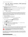
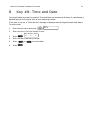
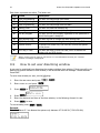
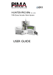
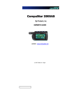
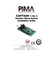
1
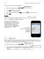
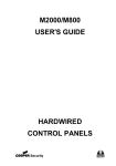
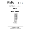
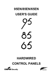
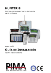
Hunter-Pro 832/8144 & Captain 8 I n t r u d e r A l a r m S y s t e m s User Guide ZA 2 Hunter-Pro 832/8144 & Captain 8 User Guide Quick Reference Key ON/OFF 1 BYPASS 3 Press for 2 seconds, enter User code and press the key... Press the key for 2 seconds... Arm to full mode One-key arming1 Display the log - Bypass zones for the next arming - Arm to “Home 1” mode One-key arming to “Home 1” mode1 Display modes menu Display “All Zones” for one minute Set the telephone numbers Arm to “Home 2” mode One-key arming to “Home 2” mode1 Set time and date - Set user codes - Set chime per zone Turn ON/Off the chime Set auto-arming by day and inactivity Display the system’s name & version Reset smoke detectors. Press briefly: display armed partitions Stop the keypad buzzer when beeping Display the service provider Initiate system tests ENTR + ENTR + Display the system’s name & version Press for 2 seconds: generate Panic alarm Press briefly: turn the keypad chime ON/OFF Factory default codes Master: Technician: 5555 1234 1 Must be enabled by the Installer 2 The exit delay countdown can expire immediately as the final door is closed. Refer to the Installer Hunter-Pro 832/8144 & Captain 8 User Guide 3 Table of Contents 1 Introduction ......................................................................................................... 5 1.1 Hunter-Pro & Captain 8 mutual features .................................................................. 5 1.2 Hunter-Pro Series features .................................................................................... 5 1.3 Captain 8 features ................................................................................................ 6 1.4 Safety & security ................................................................................................. 6 1.5 Signs and conventions in this guide ........................................................................ 6 1.6 Codes ................................................................................................................. 6 1.6.1 Master code .................................................................................................. 6 1.6.2 User codes ................................................................................................... 6 1.6.3 Short code .................................................................................................... 7 1.6.4 Duress code .................................................................................................. 7 1.7 How to enter the user menu .................................................................................. 7 1.8 The LCD keypad ................................................................................................... 7 2 Key #1: Arming & Disarming ................................................................................. 8 2.1 How to arm the alarm system ................................................................................ 8 2.1.1 With user or short code .................................................................................. 8 2.1.2 With fast (one-key) arming ............................................................................. 8 2.2 How to disarm the alarm system ............................................................................ 9 2.2.1 Using the Duress code ................................................................................... 9 3 3.1 Key #2: The Memory Log .................................................................................... 10 Log view options ................................................................................................ 10 4 Key #3: How to Bypass Zones ............................................................................. 11 5 Keys #4, #7: “HOME 1” and “HOME 2” Arming Modes ............................................. 12 6 Key #5: Display Types ........................................................................................ 13 6.1 Fast zone display ............................................................................................... 13 6.1.1 System indicators ......................................................................................... 13 6.1.2 Zone indicators ............................................................................................ 13 6.2 Scan Open Zones display type ............................................................................. 14 6.3 Disable Zone display type ................................................................................... 14 6.4 Other display types ............................................................................................ 15 6.4.1 All Zones ..................................................................................................... 15 6.4.2 Bypassed Zones ........................................................................................... 15 6.4.3 Soak Test Zones........................................................................................... 15 6.4.4 Chime Zones ............................................................................................... 15 6.4.5 All Zones Status ........................................................................................... 16 6.4.6 Show partition names ................................................................................... 16 7 Key #6: Phone numbers, SMS settings and Dialer test ............................................ 17 7.1 Edit numbers ..................................................................................................... 17 7.2 SMS Settings ..................................................................................................... 17 7.2.1 Example for SMS message ............................................................................. 18 7.3 Dialer test ......................................................................................................... 18 8 Key #8: Time and Date ....................................................................................... 19 9 Key #9: Codes ................................................................................................... 20 9.1 Master code ...................................................................................................... 20 9.1.1 How to change the Master code ...................................................................... 20 9.2 User codes ........................................................................................................ 20 9.2.1 How to set new or change a user code ............................................................ 20 9.2.2 How to delete a user code ............................................................................. 21 9.3 How to set a user name ...................................................................................... 21 9.4 How to set user settings ..................................................................................... 21 9.5 How to set user disarming window ....................................................................... 22 9.6 How to set user partitions ................................................................................... 23 9.7 How to add a key fob to a user ............................................................................ 23 9.8 How to delete a key fob ...................................................................................... 24 9.9 How to add RFID device to user ........................................................................... 24 4 Hunter-Pro 832/8144 & Captain 8 User Guide 9.10 9.11 9.12 9.13 How How How How to to to to delete RFID device .................................................................................. 25 set the Duress code ................................................................................. 25 set the Short code ................................................................................... 25 set the Door code .................................................................................... 26 10 Key #0: Auto Arming .......................................................................................... 26 10.1 How to set auto arming by day ............................................................................ 26 10.2 How to set inactivity (no detection) auto arming .................................................... 26 11 Key #: Chime .................................................................................................... 27 12 key BACK: Manual System Tests .......................................................................... 28 13 Partitions ........................................................................................................... 29 13.1 Examples .......................................................................................................... 29 13.1.1 Example A: 2 partitions, one keypad ............................................................... 29 13.1.2 Example B: 2 partitions, 2 keypads................................................................. 29 13.1.3 Example C: offices/shops .............................................................................. 30 13.1.4 Armed partitions display ................................................................................ 30 14 Other topics ....................................................................................................... 31 14.1 Arming with key switch and key fob ..................................................................... 31 14.1.1 MCT-234 key fob .......................................................................................... 31 14.2 How to enable remote programming (upload) ........................................................ 31 14.3 How to enter characters ...................................................................................... 31 14.4 How to send Panic alarm ..................................................................................... 32 14.5 How to reset Smoke, Fire and Anti-Mask detectors ................................................. 32 14.6 How to silence the keypad chime ......................................................................... 32 15 How to control via the phone ............................................................................... 33 15.1 Basic mode ....................................................................................................... 33 15.2 Full mode .......................................................................................................... 34 15.2.1 Examples .................................................................................................... 35 15.3 Comparison between the Hunter-Pro Series models ................................................ 35 15.4 Comparison between the Hunter-Pro 8144 and Captain 8 ........................................ 35 16 Troubleshooting ................................................................................................. 36 17 Appendix: Zone Location Table ............................................................................. 38 Hunter-Pro 832/8144 & Captain 8 User Guide 1 5 Introduction Congratulations on your purchase of the Hunter-Pro 832/8144 and Captain 8 Intruder Alarm Systems. Much care has been taken in developing these systems, to provide you with unprecedented peace of mind and security. The user-friendly menu with its advanced features will professionally help you to protect your premises. We recommend reading this guide in its entirely in order to familiarize you with the system and take full advantage of its features. To assure optimal safety and security, you should test your alarm system once every week. See section 12, on page 28 for details. For any further questions, please contact your local PIMA distributor. Up to date literature is available to download from our website at: www.pima-alarms.com 1.1 Hunter-Pro & Captain 8 mutual features Hybrid systems with hardwired and wireless zones Arming modes: Full, Home 1, Home 2 Menu-driven LCD and graphic keypads, and cost-effective LED keypads Optional use of partitions for perimeter zones and separate locations Automatic arming option Various codes & access options including RFID tag/keychain and key fob Authorization settings per user Up to four phone numbers to call the Monitoring Station and four to the owner Optional disarming time frame per user Constant zone, battery and phone line testing Communication channels: phone, Long-range Radio, GSM, GPRS, Ethernet Various ways to arm and disarm the system: keypad, key switch, RFID tag/keychain, auto-arming Full wireless detectors supervision Optional alarm voice messages and listen in microphone Full log, part is non-volatile Various methods to prevent false alarms Various methods to prevent burglary setup 1.2 Hunter-Pro Series features 8 to 32/144 zones Up to 32/144 user codes and RFID tags Phone remote control; Various partitioning options: Up to 16 partitions Up to 8 subsystems 6 Hunter-Pro 832/8144 & Captain 8 User Guide 1.3 Captain 8 features 8-16 zones Up to 30 user codes & RFID tags Various partitioning options: 1.4 Up to 4 partitions and subsystems Safety & security Both the Hunter-Pro 832/8144 and Captain 8 systems have been registered in accordance with the EN60950 standard We advise you the following: The alarm system as well as its wiring should be placed in a hidden and safe location, protected from rain or moisture. The alarm system may have hazards of electric shock and fire. Do not try to open the alarm system’s case: dangerous high voltages are present inside it. Refer servicing to qualified personnel only. This alarm system should be used with 230VAC 50Hz, protected by anti-electric shock breaker. To prevent electric shocks and fire hazards, do NOT use any other power source. 1.5 Signs and conventions in this guide Press a key briefly Press a key for two seconds, until confirmation beep is sounded Warning Note # In programming mode, enables (‘+’) or disables (‘-’) a parameter, erases a character 1.6 Codes 1.6.1 Master code The Master code is a 4-6 digit super user code that has all the access authorizations. To change the code, you must enter the codes menu with this code only. Replace the factory default Master code (5555), immediately after installation to prevent unauthorized and illegal operations. 1.6.2 User codes For every user you set a code, name and access authorizations. You can limit a user with a disarming time window. The system reports and logs any action taken by the user together with its code. Hunter-Pro 832/8144 & Captain 8 User Guide 1.6.3 7 Short code A two-digit code, used only for arming 1.6.4 Duress code The duress code is a 4-6 digit code for using in distress situations. When the system is armed and you are forced to disarm it, enter the duress code - the system will be disarmed, but in addition, a silent alarm will be sent to the Monitoring Station (if you are a subscriber) and the phones of the users. 1.7 How to enter the user menu The user menu is where you set parameters such as time & date, user codes and user 0 authorizations. To enter it, press for two seconds and enter the Master code. You can limit users from viewing parts of the menu - see “How to set user settings”, on page 21 for details. By default, when you enter a user code you are arming (or disarming) the alarm system. The Installer can program the system, so when you enter the code you enter the user menu. To arm the system this way, press one of the arming buttons from within the user menu. 1.8 The LCD keypad The LCD keypad is designed for maximum simplicity and durability, and it presents a decorative design. The RXN-400 & RXN-410 models are identical, except for their screen size: the 410 has a larger one. The LCD screen is made of two lines that show data regarding the system, such as time, events, faults and zone status. Up to eight addressable keypads can be connected to the system The message “Other Keypad in Use” is displayed when another keypad is in use, or when the system is remotely controlled Figure 1. The RXN-410 with the “Fast display” type 8 Hunter-Pro 832/8144 & Captain 8 User Guide 2 Key #1: Arming & Disarming You can arm the alarm system in several ways: 1. Via the keypad 2. Automatically, in a pre-defined time 3. Using key fobs, key switches and RFID devices 4. In Hunter-Pro only: by the phone 2.1 How to arm the alarm system Before arming the system, check the following: Open zones: if a zone is open, the system cannot be armed, unless it is an exit delay zone. Open zones are indicated as follows: In the “Fast zone” display type, no zone is indicated with a rectangle _ In the “Scan open zones” display type, no zone is indicated with “OP” (open) A fault occurs: if the Fault LED is flashing, check the LCD screen to see what the trouble condition is and call for service if needed. The system cannot be armed when something is faulty, unless programmed otherwise by the Installer. 2.1.1 With user or short code To arm your system, enter the Master code, user code (for restrictions, see section 9.4, on page 21) or short code (a code programmed by the Installer. See section 9.12, on page 25). If no 24-hour zone is open and no fault exist, the exit delay countdown starts with the buzzer of the keypad sounding beeps and the red ARMED LED flashing. You can now exit the premise. When the exit delay expires2, the system becomes armed: the green ARMED LED stops to flash and stays on, and the message “System Armed” is displayed briefly. 2.1.1.1 Exit and entry delay times The exit and entry delay times, which allow entering and exiting the premise without activating the alarm, are programmed by the Installer. The Installer can also program two different entry delays to different zones. 2.1.2 With fast (one-key) arming ON/OFF To arm your system using one key3, press 1 until the exit delay starts. 2 The exit delay countdown can expire immediately as the final door is closed. Refer to the Installer 3 One-key (“fast”) arming must be enabled by the Installer Hunter-Pro 832/8144 & Captain 8 User Guide 2.2 9 How to disarm the alarm system To disarm the system, enter the Master code, or user code (for restrictions, see section 9.4, on page 21). The Short code cannot be used to disarm the system. If an “Access denied” message is displayed, the user may be trying to disarm it outside its “Disarming time frame”. See section 9.5, on page 22 for details. 2.2.1 Using the Duress code The Duress code can be used when you are forced to disarm the system by an intruder. It is a disarming code only. When you enter the Duress code, you disarm the system, which sends a duress alarm to the Monitoring Station (if you are subscribed to) and the private phones. To set the code, refer to section 9.3, on page 21. 10 Hunter-Pro 832/8144 & Captain 8 User Guide 3 Key #2: The Memory Log The system keeps a log of various events, like alarms, arming & disarming, bypassing zones, and faults. Each event is kept with a time stamp and the user that is associated with, when relevant. Part of the log is kept by the power of the backup battery, during AC power failure. A log entry is made of two lines: The upper line shows the entry number and the logging time stamp The second line shows the event details. To view the memory log, do the following: Show: All Events-0 1. Enter the user menu and press 2. Press ENTR to view the log OR 3. Press Show: to view only the faults Faults Only-1 OR Show: 4. Press to view only zone alarms Zone Alarms-2 OR Show: 5. Press 3.1 to view only arming and disarming events Arming/Dis.-3 Log view options The log has four options to display the events: All the events-0: all the log entries are displayed in one list Faults only-1 Zone alarms-2 Arming/disarming-3 Press the corresponding number to view each option. Log entry example “Burglary” alarm in zone #4, named “Kitchen” - the two screens are displayed intermittently. Serial no. 29) Logging time 1 SEP 21:20 Burgl Alarm Event type 4 ~ Zone no. 29) 1 SEP 21:20 Kitchen Zone name Hunter-Pro 832/8144 & Captain 8 User Guide 4 11 Key #3: How to Bypass Zones You use the zone bypass option when you need to enter a part of the protected area while the system is armed. You can bypass zones only temporarily and only when the system is disarmed: a zone can be bypassed only for one arming and it returns to normal mode when the system is disarmed again. The letter “B” in “Fast zone display" mode indicates a bypassed zone. A service technician can bypass a zone permanently, in the case the zone is no longer needs to be protected. When you bypass a zone, you reduce the security protection of your premise: a bypassed zone does not activate the alarm when violated! Use this feature only if there is no other way, and only for the shortest possible time If need to bypass a faulty zone, call a service technician To bypass a zone for the next arming, do the following: BYPASS 3 Zone Number: Entr-Conf 1 #-Rst 1. Enter the user menu and press 2. Press a zone number 3. Press ENTR to confirm. The zone is bypassed immediately and the message “Bypassed zone” is displayed. 4. To cancel the bypassing of a zone, press # . The message “Activated zone” is displayed. As a precaution, a zone can be bypassed only for a limited time, before returns to normal mode. Example for bypassing a zone Bypassed Zone Back door -14 Zone name Zone number Example for resetting a bypassed zone Activated Zone Back door Zone name -14 Zone number 12 5 Hunter-Pro 832/8144 & Captain 8 User Guide Keys #4, #7: “HOME 1” and “HOME 2” Arming Modes “HOME 1” and “HOME 2” are partial arming modes, in which only some zones are armed, while others are not: the armed zones will sound the alarm if opened, while the disarmed zones can be occupied at the same time. Each HOME mode includes some zones, set by the Installer. Arming to the Home modes is like arming to full mode, and there is fast (one-key) arming option. To arm to HOME mode, do the following: 1. Enter the user menu 1. Press 2. Enter Master, user or Short code for “HOME 1”, or for “HOME 2” Home 1 Arming.. Exit Delay 60 Home 1 Arming.. Exit Delay 60 To arm to HOME mode with the fast arming option4, do the following: For HOME1 Arming 1. Press and hold key for “HOME 1”, or 2. Enter Master, user or Short code for “HOME 2” Enter Code Home 1 Arming.. Exit Delay 60 The exit delay for on the two HOME modes can be cancelled by the Installer 4 Fast arming is enabled by the Installer Hunter-Pro 832/8144 & Captain 8 User Guide 6 13 Key #5: Display Types Your keypad has few options for displaying information on zones, alarms, faults etc. There are two basic displaying types: “Fast display” and “Scan open zones”. The other types on the menu, except “Disable zone displaying” display various information for a minute, before they return to one of the basic types. Display Type: Fast Zn. Display To enter the “Display Type” menu, press the Master code and To view the other types, press NEXT . The types are Scan open zones, Disable zone displaying, All zones, Bypassed zones, Soaked zone, Chime zones, All zone status, and Show partition names. 6.1 Fast zone display This display type is best used if your system has up to 32 zones. Each line displays 16 zones. If you have up to 16 zones, the date and other information is displayed on the first line, and the status of the zones is displayed on second line (see the next figure). Letters and signs represent the status. If you have more than 16 zones, they will all be displayed in the same screen. The numbers imprinted above and under the LCD screen are the zone numbers. 6.1.1 Figure 1. Fast Zone mode with 16 zones System indicators The letters between the time and the date are system indicators. See the next table for details. Indicator Description P The system is communicating or testing the phone line T The system is communicating over the radio R The Relay is active (in Hunter-Pro only) S The Siren is active 6.1.2 Zone indicators The zone status indicators are listed the next table: Indicator Description - The zone is closed (normal) _ Open zone. If the zone has more than one status (e.g., it is open and alarming), the different indications are displayed intermittently A Alarmed zone: the zone was violated the last time the system was armed, or is alarming now B Bypassed zone C Chime zone F Faulty zone or a tamper switch in this zone is open 14 Hunter-Pro 832/8144 & Captain 8 User Guide Indicator Description L O Low battery in a wireless detector 24-hour zone is open or a partition (a pre-defined group of zones) is armed. # Press to display the partitions. S Electric short in the wires of the zone (this may indicate on burglary setup!) T The zone is in soak (test) mode V A wireless detector is not responding 6.2 Scan Open Zones display type In this display type, information on open zones, faults and alarms is automatically scrolled through the screen. To view the Scan Open Zones type 1. Enter the user menu and press 2. Press NEXT 3. Press ENTR 5 Display Type: Scan Open Zones In the main screen, each zone is indicated with two letters, as detailed in the next table. Letters Description OP Open zone AL The zone alarmed the last time the system was armed, or is alarming now. BP Bypassed zone FL Zone fault - the zone wires are cut SH Zone is short SV Zone supervision is lost LB Low battery in wireless zone AM Zone is anti-masked Examples 6.3 Disable Zone display type This is a version of the Scan Open Zones display type, in which open zones are ignored, and only faults and alarms are scrolled through the screen. To view this type: 1. Enter the user menu 2. Press 3. Press ENTR . The main screen is displayed with the Scan Open Zones display type, showing only faults and alarms. 5 Display Type: NEXT x2 Disable Zn. Disp Hunter-Pro 832/8144 & Captain 8 User Guide 15 6.4 Other display types 6.4.1 All Zones Use this one-minute display type to view the zone characteristics - its name, partition and type. To view the All Zones type: 1. Enter the user menu and press 5 Display Type: All Zones 2. Press NEXT x3 3. Press ENTR to view the details 4. Press NEXT to scroll through all the zones, OR 5. Press a zone number 6.4.2 Bypassed Zones Use this one-minute display type to view all bypassed zones - permanently (by the Installer) and temporarily. To view the Bypassed Zones type: 5 Display Type: NEXT x4 Display Bypass Z 1. Enter the user menu and press 2. Press NEXT to scroll through the bypassed zones 3. Press ENTR to view the details of the selected zone 6.4.3 Soak Test Zones A service technician can put a zone into soak test, if the zone generates false alarms. The max period for soak test is one week, after which the zone automatically returns to normal mode. To view the soak test zones: 5 Display Type: NEXT x5 Display Soak Zn. 1. Enter the user menu and press 2. Press NEXT to scroll through the soak test zones 3. Press ENTR to view the details of the selected zone 6.4.4 Chime Zones To view the chime zones (see section 11, on page 27 for details): 5 Display Type: NEXT x6 Display Chime Zn 1. Enter the user menu and press 2. Press NEXT to scroll through the chime zones 3. Press ENTR to view the details of the selected zone 16 Hunter-Pro 832/8144 & Captain 8 User Guide 6.4.5 All Zones Status5 This is a version of the “Fast Display” type, in which the status of all the zones is conveniently displayed in 10-zone lines. See section 6.1, on page 13 for details on the zone indicators. To view the All Zones Status type: 5 Display Type: NEXT x7 All Zones Status 1. Enter the user menu and press 2. Press NEXT to scroll through the next zones Example C--___CB--F--S_---- 1->10 11->20 In this screenshot, the status of zones 1 - 10 and 11 - 20 is displayed. The zone status is as follows: Zone Status 1, 7, 22: chime zone 2-3, 9-10: closed zones 4-6: open zones 8, 34: bypassed zone 12: faulty zone 15: zone activated or is activating the siren 6.4.6 Show partition names If your alarm system is configured with partitions (see section 12, on page 28), each keypad is allocated to a partition (or more). Use this display type to show the name of this partition on the main screen, in the Scan Open Zone type only. To stop showing it, repeat the next process. To show the partition of the current keypad: 1. Make sure the current display type is Scan Open Zones (see section 6.2, on page 14) 2. Enter the user menu and press 3. Press ENTR 5 5 Display Type: NEXT x8 Show Part Name Best used in Hunter-Pro systems with more than 16 zones Hunter-Pro 832/8144 & Captain 8 User Guide 7 17 Key #6: Phone numbers, SMS settings and Dialer test Key #6 has three sub-menus. The menus and their use are: 1. Edit Numbers: set the contact numbers that will receive audible messages on alarms and other events over the phone 2. SMS Settings: set which of the contacts will receive text messages on alarms and other events, instead of phone messages 3. Test dialer: test the validity of the phones you have programmed 7.1 Edit numbers The Hunter-Pro Series and Captain 8 alarm systems have an integrated phone dialer, which can call up to four subscribers and sound a hi-lo tone, if alarm or fault occur. A pre-recorded voice message can also be sounded6. The Installer can set which alarm types will be reported to you. The dialer attempts to call all the numbers twice - when a call is answered, the system sounds the alarm tone. The dialer will stop dialing, when: 1. The system is disarmed 2. All numbers were dialed, each number twice 3. In Hunter-Pro Series only: a stop dialing phone command is received To set a phone number: PHONES 1. Edit Enter the user menu and press Numbers ENTR Priv.Phn 1<Del=# 6 Edit Numbers ENTR Priv.Phn 1<Del=# ENTR ENTER/NEXT/BACK ENTR ... Priv.Phn 4<Del=# 2. Press ENTR 3. Enter a phone number 4. * To use the following characters, press repeatedly: “+”, “*”, “#” and “P” for one second delay (if the call is made through a phone system) 5. Press ENTR to save and set the next number ENTER/NEXT/BACK 7.2 SMS Settings Text messages are an alternative way for you to receive messages on alarms and faults. A phone number that is set to receive SMS messages will not receive audible alarms. The Installer can also program the system to send you reports on arming and disarming, by text messages. You should be aware, that SMS trechnology is far less relaible than phone system. Messages can be delayed by the service provider due to network limitations. The 1-4 numbers stand for the same programmed phone numbers. Unlike in the audible alarms, SMS messages are sent to each number only once, because SMSs are confirmed by the operator. To send text messages, you have to purchase the SMS-100 module (unless you already have the GSM-200 cellular module). 6 This feature requires the purchasing of the VU-20 voice module ... 18 Hunter-Pro 832/8144 & Captain 8 User Guide To set the numbers to receive SMS messages: PHONE Edit 6 1. SMS Numbers ENTER/NEXT/BACK Enter the user menu and press Settings ENTR NEXT SMS Settings ---- SMS Options 1234 2. Press ENTR 3. Select the desired numbers (press NEXT ) and press 4. Press ENTR ENTER/NEXT/BACK 1234 ENTR NEXT ENTER/NEXT/BACK ---- SMS Options to set a number to “+” Example 1234 Phone #2 will receive SMS messages instead of audible alarms 7.2.1 -+-- SMS Options Example for SMS message The details in the SMS message are taken mostly from the system log - only the System Name is set by the Installer. The time and date in the message indicate when the reported event was registered in the log, and not when the message was sent. 7.3 Dialer test Use the Dialer test menu to check if the phone numbers are programmed correctly. When you press a number (1-4), the system will dial that number. If a call is not received, check the number - if it is correct, call a service technician. To test the dialer: PHONE 6 Edit Numbers BACK Test Dialer Select T.No. 1. NEXT x2 Enter the user menu ENTER/NEXT/BACK and press 2. 5554444 …. (1-4) Press a number to test the corresponding phone number Dialing... ... ... 1-4 Sending... ON/OFF ... 1 Testing 1 …. Line..H1 Finished OK! Hunter-Pro 832/8144 & Captain 8 User Guide 8 19 Key #8: Time and Date You should make sure that the system’s Time and Date are accurate at all times, for maintaining a detailed log and for functions such as user disarming window. If the clock is not set, a “Clock Not Set” message is displayed and the keypad sounds fault beeps. To set the time: Hour 00:00 1. Enter the user menu and press 2. Enter the hour in 24-hour format, hh:mm 3. Press ENTR 4. Enter the date in dd:mm:yy format 5. Press 6. Press ENTR Day 01 Month 01 Year 12 NEXT or BACK to correct data 20 Hunter-Pro 832/8144 & Captain 8 User Guide 9 Key #9: Codes All codes in the Hunter-Pro Series and Captain 8 systems, except Short code, are made of 4-6 digits. Duplicate codes or codes that start with the two Short code digits are not allowed. Codes are concealed with asterisks - you cannot view or restore them. See section 1.6, on page 6 for more details. 9.1 Master code You should change the default Master code (5555) immediately after installation (see how in this section) 9.1.1 How to change the Master code To change the Master code, you must enter the User menu with the Master code. If you use a User code to enter the User menu, the Master Code menu is not displayed. To change the Master code: CODES 1. Enter the Master Code and press 2. Press ENTR 3. Enter 4-6 digits code 4. Press ENTR Master 9 Master Code ENTER/NEXT/END Code ****** (4-6) 9.2 User codes 9.2.1 How to set new or change a user code To set a new code or change one, do the following: CODES 1. Enter the user menu and press 2. Press ENTR 3. Enter a user no. and press 4. Press ENTR 5. Enter 4-6 digits code 6. Press ENTR 9 NEXT User Codes ENTER/NEXT/END User 1 (1) ENTER/NEXT/END Entr/Change Code User 1 ****** ENTR ENTER/NEXT/END (4-6) An asterisk (*) to the right of the user name indicates that the user is assign with a code. For example, “Linda” is user #16 and has a code: Linda (16 ) * ENTER/NEXT/END Hunter-Pro 832/8144 & Captain 8 User Guide 9.2.2 21 How to delete a user code To set a new code or change one, do the following: CODES 1. Enter the user menu and press 2. Enter a user no. and press 3. Press NEXT 4. To delete the code press ENTR 5. Press END 9.3 9 NEXT ENTR Delete Code ENTER/NEXT/END Code deleted Press END How to set a user name To set a name for a user, do the following: CODES 9 1. Enter the user menu and press 2. Enter a user no. and press 3. Press NEXT x2 4. Press ENTR 5. Enter up to 8-character user name. 6. Press ENTR 9.4 NEXT ENTR User Name ENTER/NEXT/END User Name 1 User 1 How to set user settings The user settings determine the sub-menus that the user will be allowed to see and change, and what data will he receive from the system. CODES 1. Enter the user menu and press 9 NEXT ENTR 2. Enter a user no. and press 3. Press NEXT x3 4. Press ENTR 5. Use the 6. Press NEXT / BACK to move the cursor left and right 7. Press ENTR to save User Settings ENTER/NEXT/END UTCMBKAORW ++++++-+--- 1 . See the next table key to allow/forbidden an action by setting it to “+” or “-” (toggle) 22 Hunter-Pro 832/8144 & Captain 8 User Guide Each letter represents an action. The letters are: Letter Action Description U Code Programming The user can set/change user codes T Tel. Programming The user can set/change phone numbers C Date Programming The user can set/change time and date M Memory view The user can view the memory log B Zone Bypass The user can bypass zones (temporary) K Use any Keypad The user can use any keypad, regardless of the partitions to which the keypad is assigned A Auto-arming Prog The user can set or change the auto-arming time O OP/CL Report-SMS The user will receive arming/disarming reports by SMS R Remote control In Hunter-Pro Series only: the user can control the system by the phone W RFID tag + Code The user will have to enter its code, when it disarms the system with an RFID device When a user tries to enter a sub-menu it is not allowed to access, an “Access Denied” message is displayed 9.5 How to set user disarming window A user can be restricted from disarming the system outside a time window. If that user will try to disarm the system outside its time window, it will be denied with the message “Access Denied! Press END”. To set a time window per user, do the following: CODES 1. Enter the user menu and press 9 NEXT ENTR 2. Enter a user no. and press 3. Press NEXT x4 4. Press ENTR 5. Enter the start and end time of the time window, in the following format: hh:mm 6. Press ENTR to save Disarm Window ENTER/NEXT/END User 1 00:00 To 23:59 To correct data, press NEXT / BACK Example The user “Karen D.” can disarm the system only between 07:30-09:30 (7:30-9:30 AM): Hunter-Pro 832/8144 & Captain 8 User Guide 9.6 23 How to set user partitions If the alarm system uses partitions (see section 12, on page 28 for details about partitions), every user can be assigning to one or more partitions. When a user is assigned to a partition, it can only operate the alarm system with keypads that are assigned to the same partition. The User Partitions screen is made of a set of the partitions, indicated with “+” or “-”, to indicate to which partition the user is assigned. The numbers imprinted bellow the LCD screen, are used here for the numbers of the partition (up to 16 partitions in Hunter-Pro Series, and 4 in Captain 8). You can allow a user to operate the alarm system from any keypad (regardless of its partitions) see parameter “K” in the “User Settings” menu (section 9.4, on page 21). To set the user partitions, do the following: CODES 1. Enter the user menu and press 2. Enter a user no. and press 3. Press NEXT x5 9 NEXT ENTR Partitioning ENTER/NEXT/END ENTR : in Hunter-Pro Series Part.for User1 ++++++++++++++++ 4. Press 5. To limit a user to a certain partition, press NEXT or BACK to move to all other partitions and set them to “-” 6. Press ENTR to save 1 2 3 4 5 6 7 8 9 10 11 12 13 14 15 16 , in Captain 8 Part.for User1 ++++ 1 2 3 4 5 6 7 8 9 10 11 12 13 14 15 16 Example Part.for -++-- User12 1 2 3 4 5 6 7 8 9 10 11 12 13 14 15 16 This alarm system has five partitions. User #12 is assigned to partitions #2 and #3. The user cannot operate the system from partitions #1, #4 and #5. 9.7 How to add a key fob to a user7 You can assign a key fob to a user. The key fob allows arming and disarming the alarm system, and some other operations. The system logs any action the user takes using the key fob. For more details, see section 14.1, on page 31. To add (assign) a key fob to a user: CODES 1. Enter the user menu and press 2. Enter a user no. and press 3. Press NEXT x6 4. Press ENTR 7 9 NEXT ENTR Add keyfob? ENTER/NEXT/END Add keyfob? Activate device You must purchase the IO-WN wireless receiver to use key fobs 24 5. Hunter-Pro 832/8144 & Captain 8 User Guide Press one of the buttons on the key fob. When the control panel receives the signal, it acknowledges it: 6. Device added! Press END Press END The letter “K” in the user code screen indicates that the user has a key fob assigned to it. For Martha example, “Martha” is assigned with a key fob: 9.8 (15 )K* ENTER/NEXT/END How to delete a key fob To delete a key fob that is assign to a user, do the following: CODES 1. 9 Enter the user menu and press NEXT ENTR 2. Enter a user no. and press 3. ENTER/NEXT/END Press NEXT x7 4. Press ENTR 5. Press END Delete keyfob? 9.9 Delete keyfob? Please wait.. .... Device deleted! Press END How to add RFID device to user RFID (Radio-frequency identification) devices are used for arming and disarming the alarm system. To use them, you will need to purchase the RD-200 RFID module. RFID is a short distance technology: you need to bring the RFID device close to the reading device briefly, to perform the action. To add (assign) a key fob to a user: CODES 9 NEXT 1. Enter the user menu and press 2. Enter a user no. and press 3. Press NEXT x8 4. Press ENTR 5. Bring the RFID device (keychain or tag) near the left side of the RFID keypad (where the RFID reader is located inside), until a confirmation ENTR Add RFID tag? ENTER/NEXT/END Pls. Attach tag TAG Received! Press END message is displayed 6. Press END The letter “A” in the user code screen indicates that an RFID device is assigned to that user. For Tina example, (1 )A* ENTER/NEXT/END Hunter-Pro 832/8144 & Captain 8 User Guide 25 You can make the user enter its code, when it disarms the system using an RFID device - see parameter “W” in section 9.4, on page 21. 9.10 How to delete RFID device To delete an RFID device that is assign to a user, do the following: CODES 1. Enter the user menu and press 2. Enter a user no. and press 3. Press NEXT x9 4. Press ENTR 5. Press END 9 NEXT ENTR Delete TAG ? ENTER/NEXT/END Tag 9.11 Removed! Press END How to set the Duress code For details on the Duress code, see section 2.2.1, on page 9. To set the code, do the following: CODES 1. Enter the user menu and press 2. Press ENTR 3. Enter a 4-6 digit code 4. Press ENTR to save 9 Duress Code NEXT X2 ENTER/NEXT/END Duress Code ****** (4-6) Hint: you can use your user code as the duress code, only switch around the two last digits 9.12 How to set the Short code The Short code is a 2-digit arming only code. When you enter the code, the Exit delay starts and the alarm system is armed. To set the Short code: CODES 1. Enter the user menu and press 2. Press ENTR 3. Enter a 2 digit code 4. Press ENTR to save Short Code ** 9 Short Code NEXT X3 ENTER/NEXT/END 26 Hunter-Pro 832/8144 & Captain 8 User Guide 9.13 How to set the Door code The door code is an activation code, mainly used for opening electric doors and gates. To set the code: CODES 1. Enter the user menu and press 2. Press ENTR 3. Enter a 4-6 digit code 4. Press ENTR to save 9 NEXT X2 Door Code ENTER/NEXT/END Door Code ****** (4-6) 10 Key #0: Auto Arming The Hunter-Pro Series and Captain 8 alarm systems have two ways be armed automatically: per day, or after a period of time in which there is no detection of one of the detectors. When the auto arming time is arriving, a 45-second pre-delay starts: the keypad will sound 2-beep alerts and the green LED will flash. After that, the normal exit delay will start and then the full system will be armed8. If partitions are in use, an X above the partition number is displayed. The Installer can set the system, so auto arming will arm the system to “Home 1” mode instead of full. To set the auto arming, do the following: 10.1 How to set auto arming by day To set the auto arming by day, do the following Auto Arm By Day ENTER/NEXT/END 1. Enter the user menu and press 2. Press ENTR 3. To select a different day, press ENTR repeatedly 4. Enter the auto arming time in hh:mm format 5. Press ENTR to save 6. Press END 10.2 Auto Arm Sunday By Day 00:00 to exit How to set inactivity (no detection) auto arming Inactivity auto arming is a feature to make sure the premise will be secured, even if the alarm system was not armed by the last person who evacuated it. You set inactivity (no detection) auto arming per partition. This gives you the flexibility to auto arm some partitions, while leaving others disarmed. If you do not use partitions set only partition #1. 8 In system with partitions, only those assigned to the keypad will be armed. Hunter-Pro 832/8144 & Captain 8 User Guide 27 When Inactivity to Arming time is arriving, a 45-second pre-delay starts: the keypad will sound 2-beep alerts and the green LED will flash. After that, the normal exit delay will start and then the full system will be armed9. If partitions are in use, an X above the partition number is displayed. To set inactivity auto arming, do the following: InactivityToArm NEXT ENTER/NEXT/BACK 1. Enter the user menu and press 2. Press ENTR 3. Enter inactivity time in minutes (up to 250) 4. Press ENTR 5. Leave the desired auto arming partitions with the “+” sign. Change to “-” (press InactivityToArm 0 Minutes Inact. Per part +++++++++++++++++ ) the partitions that will not be auto armed. Press NEXT or BACK to move right and left 6. Press ENTR to save 11 Key #: Chime When you open a chime zone while the alarm system is disarmed, the keypad buzzer sounds a series of beeps. This feature is helpful with small children and in shops, where you want to be alert if a door or window is opened. The letter “C” in the “Fast zone” display type, indicates on chime zones. To set the chime zone, do the following: Zone Number: 1 ENTR-Conf #-Rst 1. Enter the user menu and press 2. Press a zone number 3. Press ENTR to confirm. A verification message, “Chime ON” is displayed 4. To cancel a chime zone, press # . A verification message, “Chime OFF” is displayed When you press and hold the key for 2 sec, you can turn on and off (toggle) the chime feature to all the chime zones 9 In system with partitions, only those assigned to the keypad will be armed. 28 Hunter-Pro 832/8144 & Captain 8 User Guide 12 key BACK: Manual System Tests The system constantly tests the backup battery, the AC and the phone line. If your alarm system uses Ethernet or GPRS communication, additional test screens are displayed. You can perform a manual test too. To perform a test: 1. Enter the user menu and press BACK Battery Test.. … Battery Test.. Finished OK! … Finished OK! Testing Line..S1 … 2. If the test fails, the following messages appear: Battery Test.. Low Battery! 12 NOV 11 17:15 and/or Phone Line Fault Hunter-Pro 832/8144 & Captain 8 User Guide 29 13 Partitions A partition is a way to divide the premise to subsets of zones, for example, a floor, an office, and perimeter detectors. A partition can be armed separately, while other partitions are not. Users can be assigned to partitions (with the same user code) - they will be able to operate the system only via keypads that are assigned to the same partitions, and control only the zones that are assigned to these partitions. Keypads that are assigned to partitions, display only the zones that are assigned to the same partitions. There can be up to 16 partitions in Hunter-Pro Series and 4 in Captain 8. 13.1 Examples 13.1.1 Example A: 2 partitions, one keypad Figure 2. Partitions - example A10 In this example, a house is divided into 2 partitions, each occupies a separate floor. One keypad controls the two partitions, by assigning the keypad to partitions #1 and #2 (by the Installer). 13.1.2 Example B: 2 partitions, 2 keypads Figure 3. Partitions - Example B In this example, a two-floor house is divided into 2 partitions, each occupies a separate floor. Two keypads, each assigned to a different partition, control the partitions. The users can be assigned to one partition only, or be assigned to both. 10 Published under Creative Commons license (source: http://www.flickr.com/photos/axiomestates/3081558445/) 30 13.1.3 Hunter-Pro 832/8144 & Captain 8 User Guide Example C: offices/shops Figure 4. Partitions - Example D This is an example for office or shop floor. Each office/shop is assigned to a partition. The whole floor can be controlled by one keypad, with each occupant having a separate user code, remote control, key switch and RFID tag. The keypad can display the status of all partitions, though the users will only be able to control their partition. 13.1.4 Armed partitions display Armed partitions are displayed with “X”, above the partition number. 22 SEP 12 03:48 ----XXXX------XX 1 2 3 4 5 6 7 8 9 10 11 12 13 14 15 16 Armed partitions ~ 22 SEP 12 03:48 Armed Partitions 1 2 3 4 5 6 7 8 9 10 11 12 13 14 15 16 Hunter-Pro 832/8144 & Captain 8 User Guide 31 14 Other topics 14.1 Arming with key switch and key fob You can arm your alarm system using key switches and key fobs. A key switch is used in businesses mostly. To use key fobs you must purchase the I/O-WN wireless module, that supports up to 24 key fobs. 14.1.1 MCT-234 key fob Figure 5. The MCT-234 key fob The Visonic MCT-234 key fob has four push buttons, described in the next table: Button Action Arm to full mode Arm to “Home 1” mode + Arm to “Home 2” mode Disarm + Send Panic alarm Activate a device (gate, spotlight, etc.) 14.2 How to enable remote programming (upload) Your alarm system can be programmed over the phone or the network, by a service technician. For security reasons, the technician must have your approval to do it. To approve it when asked, enter the Master code and press ENTR ENTR 14.3 How to enter characters Characters are entered in the Hunter-Pro Series and Captain 8 in the same way as in cell phones. To enter more than one character using the same key, wait 2 seconds between each keystroke. See the keys and their characters in the next table: 32 Hunter-Pro 832/8144 & Captain 8 User Guide Keystrokes 1 2 3 4 5 6 7 . , ? ! 1 A B C 2 D E F 3 G H I 4 J K L 5 M N O 6 P Q R S 7 T U V 8 W X Y Z 9 Space 0 ( ) / * : + Uppercase/lowercase (toggle) Cancel/Return to previous screen [END] without saving [NEXT] Next character [BACK] Previous character [ENTR] Select/Save Key [1] [2] [3] [4] [5] [6] [7] [8] [9] [0] [*] [#] 14.4 8 # How to send Panic alarm When you activate PANIC alarm, the sirens are activated and the alarm is immediately reported to your CMS (if you are a subscriber) and your private phones. You generate a Panic alarm by pressing and holding the Asterisk and Hash keys for 2 sec, or until a confirmation tone is sounded. + # In addition to the above responses, the Installer can set the system to response in various ways. 14.5 How to reset Smoke, Fire and Anti-Mask detectors Smoke, Fire and Anti-Mask detectors are normally reset automatically, if they are activated. You can manually reset these detectors: press and hold the hash key confirmation tone is sounded. 14.6 How to silence the keypad chime To silence the keypad chime, press together END + ENTR briefly (toggle). To silence the chime in case of faults, press END # for 2 seconds. When you turn the chime Off, you disable audible indications for faults and opening of Chime zones In partitions, the chime is set separately in each keypad. for 2 seconds, until a Hunter-Pro 832/8144 & Captain 8 User Guide 33 15 How to control via the phone Phone control is not available in Captain 8. This section refers to Hunter-Pro Series only You can control the Hunter-Pro Series alarm system by any touchtone or cellular phone. You can initiate a call to the alarm system and control it, or you can answer a call from the system, for example, when you receive an alarm message. There are two modes to phone control (set by the Installer): Basic: that includes operations like arming, disarming, deactivating the sirens, and more. This is the default mode. Full: that includes the basic mode and in addition, activating devices connected to the alarm system. 15.1 Basic mode To control the system by the phone, do the following: 1. Call the alarm system (or answer a call from it) 2. After the call is answered, wait for a confirmation tone: a long tone followed by 2 beeps The system does not recognize phone commands (tones) while sounding the confirmation tone. Therefore, you must wait until the confirmation tone is over, before pressing any phone key 3. Dial the Master code or authorized user code (see section 9.4, on page 21) 4. Listen to the system status tone: Continuous: system is disarmed 3 beeps: system is armed 5. Dial a number, according to the next table. The panel confirms every command with two beeps: Dial Action 0 Stop the external siren and the dialer 1 Arm the system 2 Disarm the system (must be specifically enabled by the technician) 4 Arm the system to “Home 1” mode 5 Activate a device 6 Deactivate a device 7 Arm the system to “Home 2” mode 8 Activate listen in for one minute (using the MIC-200). Press again to extend by one minute While the system is communicating, the message “Other keypad in use” is displayed on all the keypads. If the panel does not receive any command for 60 seconds, it disconnects the call. It then remains in standby mode (with the above message displayed on the keypads) for another 60 seconds, before the message disappears. During listen in, all other phone commands are disabled. 34 Hunter-Pro 832/8144 & Captain 8 User Guide 15.2 Full mode To control the panel in full mode: 1. Repeat steps 1-4 in the previous Basic mode section. 2. To activate a device, dial [*] and a command from the following tables. 3. To deactivate an device, dial [#] and a command from the following tables. General Command Turn off the external siren and stop the dialer Arm the system Disarm the system Arm to “Home 1” mode Arm to “Home 2” mode Start listen in for 1 min. Devices connected to I/O-8N zone expanders I/O-8N Dial 1 31 2 32 3 33 4 34 5 35 6 36 7 37 8 38 9 39 10 40 11 41 12 42 13 43 14 44 15 45 16 46 Dial *00 *01 #01 *04 *07 *08 Devices connected to the control panel Output Dial Ext. SIREN 11 Int. SIREN 12 RELAY 13 SMOKE 14 ON/OFF 15 ALARM 16 AUDIO Ctrl 17 Devices connected to I/O-R RELAY expanders Expander no. 1 Expander no. 3 RELAY no. Dial RELAY no. Dial 1 51 1 67 2 52 2 68 3 53 3 69 4 54 4 70 5 55 5 71 6 56 6 72 7 57 7 73 8 58 8 74 Expander no. 2 RELAY no. Dial 1 59 2 60 3 61 4 62 5 63 6 64 7 65 8 66 Send text message with the system status to your phones Phone no. Dial 1 91 2 92 3 93 4 94 Expander no. 4 RELAY no. Dial 1 75 2 76 3 77 4 78 5 79 6 80 7 81 8 82 Hunter-Pro 832/8144 & Captain 8 User Guide 35 15.2.1 Examples 15.2.1.1 How to activate the “Ext. SIREN” output Dial the panel’s phone number the panel picks up the call wait for the confirmation tone to end dial the Master code wait for command confirmation tone to end dial *11 15.2.1.2 Deactivate RELAY#2 in I/O-R #2 Dial the panel’s phone number the panel picks up the call wait for the confirmation tone to end dial the Master code wait for command confirmation tone to end dial #60. 15.3 Comparison between the Hunter-Pro Series models Feature Zones (8 basic) Users Partitions Wireless zones Key fobs Memory total of which non-volatile 15.4 Hunter-Pro 832 8144 32 144 32 144 16 16 24 32 24 24 500 999 250 512 Comparison between the Hunter-Pro 8144 and Captain 8 Feature Zones (using expanders Zone doubling (of the onboard zones) Keypads Partitions EXP-PRO I/O-8N/PS I/O-16/PS Outputs of which onboard OUT-1000 I/O-R I/O-WN Wireless zones Key fobs Users RFiD tags Events Log of which non-volatile Captain 8 16 √ 8 4 1 12 3 1 √ 8 24 30 30 160 128 Hunter-Pro 144 √ 8 61 √ 17 8 58 7 √ 4 √ 33 24 144 144 055 250 36 Hunter-Pro 832/8144 & Captain 8 User Guide 16 Troubleshooting Faults are indicated by the flashing red LED in the keypad, a description of the fault is displayed, the buzzer sounds beeps and the system logs it. In addition, the service technician can set the system to report it to the Central Monitoring Station, to send an alert by the telephone, to trigger an output and more. If more than a single fault occurs, the display will scroll between them. Unless instructed otherwise, call a service technician when the system reports on faults. Fault Description and troubleshoot Low Battery Occurs after a prolonged power failure or when the battery is outdated. If the fault lasts more than one day, or there was no previous power failure, call a service technician. Mains Fault Appears during a power failure. Clock Not Set Appears following a prolonged power failure during which the backup battery was completely discharged. Set time and date (see page 19). Phone Line Fault Perform phone line test (see key BACK: Manual System Tests on page 28). Make sure no other telephone appliance is using the line. If the fault persists, call a service technician. Tamper 1 Tamper switch 1 is open. Tamper 2 Tamper switch 2 is open. Expander X Tamper Expander X’s box or tamper is open. Expander X Fault Expander X is faulty. EXP X Voltage Low voltage to the I/O-8N zone expander. Expander X Mains Expander X has no Mains voltage. Expander X Batt Expander X has low battery fault. Keypad X Tamper Keypad X’s tamper switch is open. Low Voltage Appears before the backup battery is completely discharged, usually during a prolonged power failure. Call a service technician immediately! Wireless Z Fault A wireless detector (zone) is faulty (no supervision signal). MS COM Fault Failure to communicate with the Central Monitoring Station over the phone. KEYPAD NOT CONNECTED No communication between the keypad and the control panel. GSM Unit Fault The GSM-200 module cannot be detected or is faulty. GSM Link Fault GSM limited or no reception. GSM Comm. Fault GSM communication failure with Central Monitoring Station #1. GSM Comm. 2 Fault GSM communication failure with Central Monitoring Station #2. SIM Card Fault SIM card is not detected or is faulty. Wireless System I/O-WN module cannot be detected or is faulty. W/L Unit Tamper I/O-WN box tamper is open or faulty. Other keypad in use Other keypad is in use or the system is remotely controlled via the telephone. Hunter-Pro 832/8144 & Captain 8 User Guide 37 Fault Description and troubleshoot Check Keypad Number The keypad’s ID is not configured properly. Keypad X Fault Keypad X is faulty. Zone Fault A zone (include. Wireless zone) is tampered or faulty. Possible tampering! Detec Vol. Fault Detector voltage is faulty due to possible tampering. Call a service technician immediately! SMS Com. Failure SMS communication fault. Install SMS Unit No SMS unit is detected or the unit is faulty. Network Fault Network communication with the Central Monitoring Station is faulty. IO-R X Fault The I/O-R relay expander is faulty. IO-R X Tamper The I/O-R relay expander tamper is open. IO-R X Voltage Low voltage in the I/O-R relay expander. IO-R X Mains IO-R X has no Mains voltage. IO-R X Batt IO-R X has low battery. Wireless Jamming The wireless receiver (I/O-WN) is jammed. Supervision A wireless detector “life signal” has not been received. Int. siren fault The internal siren is faulty. Ext. siren fault The external siren is faulty. Video X fault Communication fault between the panel and the video unit VVR #X. Video X power fault Voltage fault in VVR #X. net4pro fault Communication fault between the panel and the net4pro network card. 38 Hunter-Pro 832/8144 & Captain 8 User Guide 17 Appendix: Zone Location Table No. 1. 2. 3. 4. 5. 6. 7. 8. 9. 10. 11. 12. 13. 14. 15. 16. 17. 18. 19. 20. 21. 22. 23. 24. 25. 26. 27. 28. 29. 30. 31. 32. 33. 34. 35. 36. 37. 38. 39. 40. 41. 42. 43. 44. 45. 46. 47. 48. 49. 50. 51. 52. Zone Location No. 53. 54. 55. 56. 57. 58. 59. 60. 61. 62. 63. 64. 65. 66. 67. 68. 69. 70. 71. 72. 73. 74. 75. 76. 77. 78. 79. 80. 81. 82. 83. 84. 85. 86. 87. 88. 89. 90. 91. 92. 93. 94. 95. 96. 97. 98. 99. 100. 101. 102. 103. 104. Zone Location Hunter-Pro 832/8144 & Captain 8 User Guide No. 105. 106. 107. 108. 109. 110. 111. 112. 113. 114. 115. 116. 117. 118. 119. 120. 121. 122. 123. 124. Zone Location 39 No. 125. 126. 127. 128. 129. 130. 131. 132. 133. 134. 135. 136. 137. 138. 139. 140. 141. 142. 143. 144. Zone Location Installer Details: Name: ________________________ Phone: ____________________________ Cellular: ___________________________ Company: _________________________________________________________ Phone no.: _________________________ Date of installation: Day _____ Month _____ Year _______ End of service: Day _____ Month _____ Year _______ 40 Hunter-Pro 832/8144 & Captain 8 User Guide Limited warranty PIMA Electronic Systems Ltd. does not represent that its product may not be compromised and/or circumvented, or that the Product will prevent any death, personal and/or bodily injury and/or damage to property resulting from burglary, robbery, fire or otherwise, or that the Product will in all cases provide adequate warning or protection. The User understands that a properly installed and maintained equipment may only reduce the risk of events such as burglary, robbery, and fire without warning, but it is not insurance or a guarantee that such will not occur or that there will be no death, personal damage and/or damage to property as a result. PIMA Electronic Systems Ltd. shall have no liability for any death, personal and/or bodily injury and/or damage to property or other loss whether direct, indirect, incidental, consequential or otherwise, based on a claim that the Product failed to function. Please refer to a separate warranty statement found on PIMA website at: http://www.pima-alarms.com/site/Content/t1.asp?pid=472&sid=57 Warning: The user should follow the installation and operation instructions and among other things test the Product and the whole system at least once a week. For various reasons, including, but not limited to, changes in environment conditions, electric or electronic disruptions and tampering, the Product may not perform as expected. The user is advised to take all necessary precautions for his/her safety and the protection of his/her property. This document may not be duplicated, circulated, altered, modified, translated, reduced to any form or otherwise changed; unless PIMA’s prior written consent is granted. All efforts have been made to ensure that the content of this manual is accurate. Pima retains the right to modify this manual or any part thereof, from time to time, without serving any prior notice of such modification. Please read this manual in its entirety before attempting to program or operate your system. Should you misunderstand any part of this manual, please contact the supplier or installer of this system. Copyright 2014 PIMA Electronic Systems Ltd. All rights reserved. PIMA Electronic Systems Ltd. 5 Hatzoref Street, Holon 5885633, Israel Tel: +972.3.6506414 Fax: +972.3.5500442 Email: [email protected] Web: http://www.pima-alarms.com 4 4 1 0 4 1 3 *4410413* Version: A, ZA en, Apr 2014