1
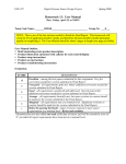
MULTIFUNCTIONAL
ELECTRONIC TARGET II
USER'’S MANUAL 9) Wall Mount
1) Power / Mode
Button
8) External Switch
2) Volume
7) Reserved
The G&G second generation MET has
increased sensitivity, 4 LEDs, volume
speakers and can be mounted on a wall. An
independent power source is not required
when linked up to multiple units; linked units
will only require one power source. The
second generation has 7 game settings
(previously 4) waiting to be challenged.
DIP3 for colors choices (blue/ red).
Resetting is not required for changing sound effects,
however, switching color choices requires resetting.
Product Features
Dimension / H95 X Ø125 mm Weight / 425g
Number of USB power
supplies for M.E.T. setup
The number of USB power supplies
depends upon the length of wire used in
the configuration and the number of
targets. There are two scenarios:
1 The number of targets is less than 10,
1 USB power supply is required for every 15
meters of wire. (e.g. for 9 targets, each target will
use 5 meters of wire. In this case, you will need 45
meters of wire. As one USB power supply is
required at every 15 meters; you will need 3 USB
power supplies.
Please see figure 1 for more details.
Less than 10 targets:
Length = 45 meters/ USB power supplies = 3
15 m
15 m
(15m)
15 m
(30m)
(45m)
AC USB power adapter
USB port of power bank
Do not connect the USB port to a computer.
USB Adapter : Output above 2.0A
Model : G-11-068 (US type) / G-11-069 (EU type) >(optional)
B) Visual & Sound Effects
During stand-by Ready mode – Blue light displayed.
Once hit – Red light displayed.
When flashing red – The battery power is low.
Mode 4 and mode 6 has different colors.
5) Screw Base –1/4"-20UNC inclusive screw.
6) Signal port 2–Used to connect one target to another
DIP switch 3 – Blue/ Red options. Reset/power on unit
again to activate.
7) Reserved –No usage.
8) External Switch –
selects the sound effects (no need to reset).
Model : G-11-071 Standard / G-11-070 Metal >(optional)
Product sensitivity between 0.3J~2J (@ 10 Meter distance)
(same functionality as Port 1).
9) Wall Mount –3/16" x L25mm wall mount dimensions
(recommend flat screw – philip’s).
2 The number of targets is more than 10.
(e.g. for 11 targets, each will use 1 meter of wire.
You will therefore need 11 meters of wire. In fact,
one additional USB power supply will be required
for the eleventh target. Please see figure 2 for
more details.
More than 10 targets:
Length = 30 meters/ USB power supplies = 3
10 m
10 m
(10m)
Fig. 2
10 m
(20m)
AC USB power adaptor
4 different sounds (internal speakers) – DIP switches 1&2
C) 0.3 ~ 2J Sensitivity
same functionality as Power/Mode.
(30m)
USB port of power bank
Button Selections
1) Hold button for 2 seconds to turn on/off
2 sound effects indicate the unit has been powered on.
The second sound means you have entered Shooting
Mode and are ready for mode selection.
2) Mode selection–After powering on, quickly press
Fig. 1
Model : G-11-065 >(optional)
more power sources is recommended.
2) Volume Control –Up and down.
3) Signal Port –For connecting other units.
4) DIP Switch –DIP 1&2 for sound effects
4) Dip Switch
Power Bank : Output above 2.0A
targets is increased, some instability may occur; adding
Power On/Off. Mode switch. Start button.
5) Screw Base
Input : DC 5V (Operating current : 75 ~ 600mAMAX)
using additional MET units. If the distances between
1) Power/ Mode
6) Signal Port 2
A) Power Source
It is recommended to add more power sources when
Control Panel
3) Signal Port 1
Functionality
the start button to select the desired modes.
Mode selection is available 3 seconds after power up.
For example, quickly pressing twice will take you to Mode
2 (the red light will flash twice).
3) Different power up selections
D) 360º Covering Angle
When MET becomes unstable due to
interference from other sources, the MET
system will shut down automatically
to keep the fairness of the game.
E) 1~25 Targets (max) Multi-Targets,
25 being Maximum
When the distance between units is greater than 15
meters, it is recommended to add a power source for
every 3 units. Normal usages: 0.5 meters apart - 8 units
can share one power source. Please refer to the "Wiring"
section for more information.
F) Silicon domes (target cover), durable for at
least 50,000 hits
G) Wall mounting specifications:
3/16" x L25mm (recommend flat screw – philip’s head)
H) Screw dimensions for inbox are: 1/4"-20UNC
I) Operating temperature: -5 ~40 ºC
Trouble Shooting
A) When the auxiliary targets malfunction after powering
on, remove the primary target, and connect it to a stand
alone target. Do the same for the other targets.
B) Sensor malfunction may be caused by a misaligned
sensor ball - the target will flash red and blue or display
a constant red light after powering on. This can be fixed
by tapping the target 2 to 3 times. This causes a change
in air pressure which may help the sensor ball
recalibrate.
M.E.T.II
User’s Manual
1. Standard
Mode: Hold the start
button for 2 seconds to
turn on/off. All connected
units will flash with the Master unit.
2. Challenge Mode: turn off/on the unit
by following the steps in Standard Mode. To
select a Challenge Game Mode, press the
start button multiple times (number of
presses dependant on the mode) and hold
the button on the last press for more than
one second. For example, to select the
"Random" Game Mode, press 4 times and hold
the 4th press for 1 second to activate the mode.
After activation, the Master unit will flash 4 times
(number of flashes dependant on the mode selected)
with a sound effect (other linked units will not flash)
and then turn off. After entering a challenge mode, you
will only need to press the button once to activate the
"Random" game mode. After you have finished the
game, all units will return to the initial challenge mode,
except a game in the "Time Bomb" mode.
In Challenge Mode, you will not be able to select the
"Competition" or "Quick Draw" games.
G1-201312-04 英
7 Challenge
Modes
1) Competition
2) Versus
3) Random
4) Practice
5) Search and Destory
6) Hostage Rescue
7) Time Bomb
User’s Manual
Mode
Mode
Mode
Mode
Mode
Mode
Mode
7 different game modes. First, turn on the target as Master Target.
MULTIFUNCTIONAL ELECTRONIC TARGET II
game play will be auto reset. The Master target will return
to standby mode with the the blue light on and be ready
for replay.
hit. To set up the game for this mode, targets should be
hidden or covered without being seen easily. Shooters
in this mode should rely on hearing instead of sight.
3) Random Mode
6) Hostage Rescue Mode
Press the start button three times to select this mode. In
Press the start button six times to select this mode. This
this mode, the Master target will display a blue light with
the other linked targets in standby mode. As soon as the
blue light is hit, the next target will be activated randomly.
Once all the targets are shot, the last target will turn solid
red for 5 seconds, signaling the end of the round. The unit
will auto reset for the next round.
mode is the most difficult mode for most shooters.
Targets will switch between blue and red lights
randomly. The blue light indicates that the target should
be shot at, whereas the red light indicates targets that
should not be shot at. This simulates a hostage
situation when blue lights should be determined as
terrorists, and red lights are hostages. When the red
4) Practice Mode
light has been shot, the target will stay in red to indicate
Press the start button four times to select this mode. In
the hostage has been killed. After the game ends,
this mode, all targets will display a blue light. The target
shooters can compare their speed and accuracy.
will turn red when hit and the last target will blink red for
five seconds, signaling the end of the round. The unit will
auto reset for the next round.
7) Time bomb Mode
Press the start button seven times to select this mode.
1) Competition Mode (default setting)
2) Versus Mode
Press the start button once to select this mode. In this
Press the start button twice to select this mode. In this
mode, all targets are in stand-by mode with Blue lights
mode, only the master target is in stand-by mode with
Press the start button five times to select this mode. In
timer zeroes, the target will turn red and turn off all
on. When the first target is hit, it will turn Red and all
blue lights on. After the master target has been hit, it will
this mode, the shooter will be challenged by locating the
other targets linked with it. This mode simulates a time
targets’ light will be shut off. This mode will determine
flash a blue light and count down for five seconds. Once
target from the sound it makes. The target will display a
bomb situation. If the shooter does not hit the target
who hit the target first. Press the start button again to
the countdown is done, all targets will turn solid blue. The
blue light and constantly make a noise. The noise will
within three seconds, the bomb goes off and ends the
reinitiate competition mode.
first target that was hit will turn red for five seconds and
stop and the light will turn red once the target has been
game.
Abnormal Status
Connection
Other than having different lengths, there are
2 types of lines/cables.
Sensor Abnormality - Troubleshooting Guide
1) A misaligned sensor ball will cause the MET to flash red
and blue or constantly display red after powered on.
2) A red light flashes when low on power.
How to link up targets
1) Data cable :
Connects 2 MET units.
Initial target (ex. 5 targets)
1) Link up targets in lines; do not link in a closed loop
2) It is recommended to place the initial target first in line.
Attention
2) Signal line + USB electrical line
Coupled with a signal line, the USB electrical line can
support both signals and electricity.
When the signal line is over 30 meters, an extra power
source needs to be added.
If the first MET unit has a 15 meter line and the second
MET unit also has a 15 meter line, the second MET unit
will need to use the USB line as a power source.
Power Distributions
To link 25 units, for example, use 6 sets of wires (signal
wire + ground wire) for the first 7 units. Between the 7th
and 8th, add the USB power wire (signal wire + USB
power wire + ground wire) and connect the ground wire
from the 1st unit to the 8th unit's ground wire (only
required when signal is unstable.)
5) Search and Destory Mode
Status/ Condition of the MET :
1) MET flashes red and blue. Tapping the unit is ineffective
and the red and blue flashing is frequent.
2) MET displays the normal state but sensors are inactive
or have decreased sensitivity.
3) When turned on, and the MET displays red even without
firing at it. If the above conditions are displayed, it
indicates that there is sensor abnormality in the MET.
Please refer to the troubleshooting
method below:
Step 1: Check the 2nd generation
MET Cover (the green part of the MET)
for damages. If there are damages and
the sensors are unresponsive, please
replace the MET Cover.
1) Check batteries, wires…etc. before use.
2) The longer the distance the weaker the
signals.
Please
take
precautions
and
follow
the
manufacturer suggested guidelines.
2
3
This is one of the tricky modes where the target will
display a solid blue light for three seconds. Once the
Step 5: Remove the small
styrofoam ball and store it in a
safe place.
5
6
Step 6: Spray a small
4
amount of Anti-Static spray
inside the compartment from
where the Styrofoam ball was
housed.
Caution:
Do not over spray Anti-Static spray inside the housing or
the spray will not dry out fast enough and cause the
Styrofoam ball to stick on the housing. It is recommended
to spray the Anti-Static spray with 30cm distance.
7
Step 7: Spray a
small amount of
Anti-Static Spray on
the inside/ bottom of
the small black cap.
Step 8: When the Anti-Static Spray is
dry, reinstall the small styrofoam ball
into the compartment and reinstall the
small black cap. Make sure the small
black cap clicks closed. If the cap does
not properly cover the compartment,
then electrostaticity will deform the
copper plate, causing malfuncitions.
3) If the target displays an abnormal status, has a loose
connection
wire,
and/or
is
low
in
power,
etc.,
troubleshoot the problem before use to avoid causing a
chain reaction on other targets.
4) When not in use, please turn off the power and
remove power sources, to save energy and for safety.
5) Warning: please use original accessories to avoid
unnecessary occurances.
Step 2: Remove the skirt cover. Step 3: Remove the MET Cover.
Step 4: Remove the small black cap by pulling in the
opposite direction from the copper plate and wires (as
depicted). You can then check if the electrostaticity is too
strong. This is caused by incorrect positioning of the small
Styrofoam ball.
10
Step 9: Repeat Steps 1~8 on the auxiliary MET Targets.
Step 10: Reinstall MET Cover and Skirt. Align the arrow on
the Skirt with the mounting holes.
Note: If you accidently cause the copper plate to become
deformed, it is recommended that you gently tweak it outwards
3-5 degrees. If you have any questions, please contact our
support line.

![ManualCover-3Panel10_03 [Converted]](http://vs1.manualzilla.com/store/data/005711777_1-408df82eece155ec198a9b3b174c8b0a-150x150.png)