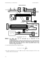
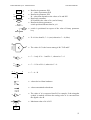
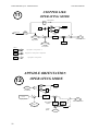
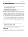
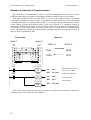
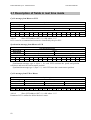
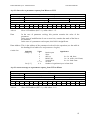
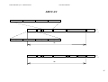
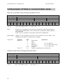
1
LVD ( LVD1, LVD2, LVD5, LVD10, LVD15 ) User’s Manual Rev. 1.8 February 2004 (Software Rel. 55) Parker Hannifin S.p.A. - Divisione S.B.C. LVD User’s Manual DIGITAL-LOCK VARIABLE RATIO POSITIONER ELECTRONIC CAM STEP MOTOR SIMULATION EASY MAINTENANCE TORQUE CONTROL ACCELERATION CONTROL SOFTWARE TOOLS AVAILABLE RS-485 or RS-422 SERIAL LINK SPINDLE ORIENTATION FOR TOOL CHANGING BUILT-IN P.L.C. CanBus interface Parker Hannifin S.p.A. Divisione S.B.C. 20092 Cinisello Balsamo (Milano) - Italy Via Gounod, 1 tel. +39-02-66012478 fax +39-02-66012808 e-mail: [email protected] LVD : everywhere for any application. Parker Hannifin S.p.A. - Divisione S.B.C. LVD User’s Manual DANGER HIGH VOLTAGE ! Internal circuits of the LVD drive carry high voltages that can cause serious injury or kill. Do not open the drive or attempt to access internal parts while it is connected to the power supply. If you need to access internal parts, wait at least 15 minutes after power down before proceeding to allow the condensers to discharge. The User is responsible for ensuring that the drive is installed in compliance with established work health and safety regulations. For the purposes of applicable regulations, note that the drive is classified as a component and not a machine. All tampering or unauthorised work performed on the drive will automatically invalidate the warranty. Warranty cover is otherwise provided for 1 (one) year. This user manual is applicable to the standard version of the drive. Parker Hannifin S.p.A. Divisione S.B.C. declines all liability for any whatsoever form of damage deriving from improper use of the drive. Installation and maintenance of the drive and connected equipment must be performed exclusively by qualified and trained personnel with basic skills in electronics. Commissioning of the drive must be performed exclusively by qualified and trained personnel with advanced skills in electronics and drive technology. Training courses can be supplied by Parker Hannifin S.p.A. Divisione S.B.C. on request. The quoted performance of the LVD drive is guaranteed only when used with series MB synchronous permanent magnet motors manufactured by Parker Hannifin S.p.A Divisione S.B.C. ISBN 0402041600 2 Parker Hannifin S.p.A. - Divisione S.B.C. LVD User’s Manual TABLE OF CONTENTS 1 INTRODUCTION...................................................................................................................... 5 1.1 General information....................................................................................................... 5 1.2 Product description ........................................................................................................ 5 1.3 Identification .................................................................................................................. 6 1.4 Main hardware specifications........................................................................................ 7 1.5 Main software specifications.......................................................................................... 8 1.6 Compliance with EMC standards .................................................................................. 8 1.7 Safety .............................................................................................................................. 8 2 INSTALLATION....................................................................................................................... 9 2.1 Safety instructions .......................................................................................................... 9 2.2 Tips for interference suppression................................................................................. 10 2.3 Mains filter installation instructions............................................................................ 11 2.4 Connector layout .......................................................................................................... 12 2.5 Power connections ....................................................................................................... 15 2.6 Power connection diagrams......................................................................................... 16 2.7 Signal cable connections.............................................................................................. 20 2.8 Signal cable connection diagram................................................................................. 20 2.9 Frequency input connection ......................................................................................... 20 2.10 Simulated encoder output............................................................................................. 22 2.11 Serial line connection................................................................................................... 22 2.12 Backup.......................................................................................................................... 23 2.13 Status LEDs .................................................................................................................. 23 3 PARAMETERS AND PROGRAMMING .............................................................................. 24 3.1 Using the optional keypad............................................................................................ 25 3.2 Commissioning the LVD Drive .................................................................................... 26 3.3 Basic parameters.......................................................................................................... 29 3.4 Basic commands........................................................................................................... 34 3.5 Speed control loop calibration..................................................................................... 35 3.6 Operating modes .......................................................................................................... 41 3.7 Torque control.............................................................................................................. 41 3.8 Acceleration control..................................................................................................... 41 3.9 Maintenance and commissioning mode ....................................................................... 42 3.10 Positioner ..................................................................................................................... 43 3.11 Digital locking.............................................................................................................. 45 3.12 Stepper motor simulation ............................................................................................. 46 3.13 Spindle orientation ....................................................................................................... 47 3.14 Digital locking + Positioner ........................................................................................ 47 3.15 Position control with CanBus or electronic Cam ........................................................ 48 3.16 Block diagrams............................................................................................................. 50 3.17 Other useful functions .................................................................................................. 58 4 Programming digital inputs and outputs .................................................................................. 61 4.1 The “pico-PLC”........................................................................................................... 61 4.2 Examples and applications .......................................................................................... 65 4.3 Programming with PC2LVD........................................................................................ 73 5 SERIAL INTERFACE ............................................................................................................. 74 5.1 Communications protocol ............................................................................................ 74 3 Parker Hannifin S.p.A. - Divisione S.B.C. LVD User’s Manual 5.2 Serial addresses and parameter lengths ...................................................................... 78 6 CAN BUS................................................................................................................................. 81 6.1 Description of fields in real time mode ........................................................................ 82 6.2 Description of fields in communication mode.............................................................. 86 Appendix A : LVD mechanical dimensions ................................................................................. 88 Appendix B : MB series motor connectors................................................................................... 89 Appendix C : hardware characteristics ......................................................................................... 90 Appendix D : conventions ............................................................................................................ 91 Appendix E : software timer intervals .......................................................................................... 91 Appendix F : pico-PLC default program ...................................................................................... 92 Appendix G : flash information .................................................................................................... 93 Appendix H : troubleshooting....................................................................................................... 94 Appendix I (accessoires) : “IOBOX” .......................................................................................... 96 Revision history ............................................................................................................................ 98 4 Parker Hannifin S.p.A. - Divisione S.B.C. LVD User’s Manual 1 INTRODUCTION 1.1 General information This manual describes the procedure for installing and commissioning the LVD frequency converter for brushless motors. Read all the chapters and the revision history thoroughly before using the equipment. 1.2 Product description The LVD is a digital frequency converter for driving brushless motors. The adoption of a parametric Operator Interface makes drive configuration procedures faster and more repeatable. The large number of different configuration possibilities makes the drive suitable for a broad range of applications. A high power 16 bit micro-controller allows speed control with the characteristics required of a servo controller, plus a range of auxiliary functions that can help reduce the presence of control electronics in the application and thus permit considerable economic savings. In addition to the positioner functions with trapezoidal profile, digital locking, spindle orientation, stepper motor simulation, torque control and acceleration control, the LVD drive also has an internal PLC. The drive PLC adopts the most diffused industrial programming standards and offers considerable freedom for use of inputs and outputs. It also enables users to develop a range of additional functions that are not among the basic features of the drive, such as: electronic cams, adaptation of loop gains in relation to speed or space, torque monitoring for controlling tool wear, etc.. The LVD drive is complete with an RS422/RS485 serial interface which can be used for configuration, monitoring and simultaneous transmission of commands to a multiple system comprising up to 32 LVD units. The drive is also compatible with standard operator panels that support the S.B.C. protocol. The drive is also equipped with a CanBus interface in communication mode and in real time mode. Using the CanBus interface makes it possible to obtain a high bandwidth digital link, t thereby simplifying system wiring requirements. With the CanBus interface LVD's I/Os can be used as remote master I/Os. 5 Parker Hannifin S.p.A. - Divisione S.B.C. LVD User’s Manual 1.3 Identification LVD drives are available in five models: LVD1, LVD2, LVD5, LVD10 and LVD15, where the number stands for rated current (in amperes). The right hand side of LVD drives bears an identification label showing all the most important identification data. Please make a note of the information on this label before requesting technical information from Parker Hannifin S.p.A. Divisione S.B.C.. An example of the identification label is shown in the following figure: Parker Hannifin S.p.A. VIA GOUNOD 1 - 20092 CINISELLO B. (MILANO) - ITALY LVD 5 POWER INPUT S/N 980001 POWER OUTPUT 3XAC230V 4.6A 3XAC230 5A 50..60 Hz 0..500 Hz READ INSTALLATION INSTRUCTION MANUA L USE COPPER WIRE BEFORE INSTALLING RATED 60/75°C 6 Parker Hannifin S.p.A. - Divisione S.B.C. LVD User’s Manual 1.4 Main hardware specifications Parameter Power circuit power supply Control circuit power supply Models Rated output current Peak output current (4 s) Output power at motor shaft Dissipation from control electronics Dissipation from power stage Ambient temperature Internal braking resistor dissipation Feedback Power stage switching frequency Maximum basic output frequency Protection category 24V digital inputs = 24V digital outputs = / 100mA / PNP Voltage free contact digital outputs Encoder simulation RS-422 Frequency / sign or encoder input Analog reference Auxiliary analog input Auxiliary analog output Tacho generator emulation output Serial line Field bus U.M. V~ V= Value 230 ± 10% 24 ± 10% - 1.5A LVD1 A A kW W W oC W kHz Hz No No No steps/rev kHz V V V V LVD2 1.25 2.5 2.5 5 .345 .700 LVD5 LVD10 5 10 10 20 1.5 3 18 18 28 45 87 45 120 resolver (speed 1) 16 450 IP 20 8 6 1 128..4096 800 / 200 ±10 diff 15 bit ±10 diff 10 bit ±10 - 8 bit ±10 V RS-422 / RS-485 CanBus LVD15 15 30 4.5 120 7 Parker Hannifin S.p.A. - Divisione S.B.C. LVD User’s Manual 1.5 Main software specifications The following functionalities are implemented in the basic software supplied with the LVD drive: • • • • • • • • • • • Speed control Advanced torque limits manager Speed windows management Positioning with trapezoidal speed profile Digital locking functions with variable transmission ratios and phase shifting Spindle orientation Stepper motor simulation Torque control with superimposed speed control Acceleration ramp control with superimposed speed control Simplified maintenance and start-up mode Built-in PLC for advanced input/output programming functions 1.6 Compliance with EMC standards Immunity: EN50082-1* / EN50082-2 IEC1000-4-2 (ex IEC 801-2) IEC1000-4-3 (ex IEC 801-3) IEC1000-4-4 (ex IEC 801-4) level 3 level 3 level 4 Basic immunity specifications Electrostatic discharge immunity Electromagnetic field immunity Fast transient burst conducted immunity Compatibility: EN50081-1* / EN50081-2 EN55011 group 1, class A EN55011 group 1, class B* Basic radio interference specifications Measurement limits for radio interference Measurement limits for radio interference 1.7 Safety Safety standard Low voltage directive Applied standard EN60065, EN50178 73/23/EEC amended by 93/68/EEC EN60204-1 * Conformity for use in domestic or industrial surroundings depends on the nature of the installation. 8 Parker Hannifin S.p.A. - Divisione S.B.C. LVD User’s Manual 2 INSTALLATION • The LVD drive must be installed in a vertical position (with the power terminal board at the top). • Leave at least 190 mm (7.5”) clearance above and below the drive. 2.1 Safety instructions • Make sure the drive is appropriately sized for the motor you intend to connect. Compare rated voltage and current values. • Wire up the electrical panel/drive/motor in accordance with the instructions in this section of the manual, taking into consideration EMC requirements and established safety regulations. • The User is responsible for installing fuses on the drive AC power supply line. • Power conductors and control circuits must be kept apart (by at least 200mm - 8” -) and, when they must cross, intersections must be at right angles. Motor conductors and mains power conductors must never be parallel. • All power wires must be sufficiently sized (refer to the table in heading 2.7; compliance with IEC227-2 must be guaranteed in all cases). • Wires connected to the drive by means of the terminal strip must not be soldered (EN60065, art.15.3.5). • Make sure drive and motor are properly earthed. • Make sure that the maximum voltage on terminals L1, L2, L3 does not exceed t he rated voltage by more than 10% in the worst possible case (see EN60204-1, section 4.3.1). Excessively high mains feeding voltage can damage the drive. • Do not detach electrical connections when the drive is connected to the power supply. • Follow all the installation instructions in this manual step by step. If you are in doubt, contact S.B.C. Customer Service. • Dangerous voltages may still be present for up to 60 seconds following mains disconnection and system power-down; do not touch power cables during this time interval. • Do not open the drive casing. This action is potentially dangerous and will automatically invalidate the warranty. Installation and wiring must be carried out with the entire electrical panel disconnected from the power supply. Make sure that the drive enable command is disconnected from the emergency circuit. Qualified technical personnel must preside when the power panel is powered up for the first time. 9 Parker Hannifin S.p.A. - Divisione S.B.C. LVD User’s Manual 2.2 Tips for interference suppression Because of the high speed voltage wavefronts in PWM, high levels of stray current may sometimes flow through capacitive couplings and earth systems. Stray currents of this type can affect other functional units. Therefore, in relation to the geometrical dimensions of the system (drive, motor cables, motor), it is advisable to calculate a certain amount of spurious energy. Spurious energy generates EM radiation that can interfere with the operation of nearby systems Existing standards do not impose limits for this type of radiation. Preventive measures: Basic methods of preventing spurious emissions are: decoupling of the drive from its surroundings, a properly executed conductor system to neutralise voltages (earthing) and adequate shielding. Screens, filters and drives must have a large contact area to achieve the maximum possible decoupling and hence optimum noise suppression; attention must be paid, however, to the entire installation as this is one of the most important precautions for obtaining efficient noise suppression. High frequency interference takes the form of radiation, especially from motor lines. This effect can be reduced with appropriate shielding. Another essential counter-measure for noise suppression is the use of filters. The use of filters is aimed at reducing conducted interference on wiring and the return of conducted interference to source (Drive) through routes offering the lowest impedance. This method provides effective protection for other systems connected to the same electrical line, also protecting the drive from interference originating from other systems. When installing filters consider the mains input and motor feeding output. There are various ways of connecting the power supply to the LVD drive; by using a transformer with an electrostatic screen between primary and secondary windings it is possible to dispense with the installation of EMC filters; on the contrary, EMC filters are required if you use an autotransformer, a transformer without an electrostatic screen or a direct mains connection. 10 Parker Hannifin S.p.A. - Divisione S.B.C. LVD User’s Manual 2.3 Mains filter installation instructions To obtain electromagnetic compatibility in compliance with established standards, EMC requirements are of critical importance when designing control panel configuration. To get the best results from the filters, follow the instructions in this chapter carefully, because even a complex and expensive filter is ineffective unless it is installed taking EMC aspects into consideration! Avoid: - routing noise emitting cables in parallel with "clean" cables - parallel cables, especially in the vicinity of the filter (ensure physical separation) - cable loops (keep cables as short as possible and close to the common potential). Additional measures: - With the exception of mains cables to the filter, all power and control wiring must be screened and, wherever possible, kept segregated (minimum distance 20 cm). If control and power cables must cross, the intersection must be at a right angle. - Shielded cables must be installed on a copper bar by means of a high conductivity wire clamp. The area of contact must be as large as possible and the shield must be unbroken. In general the shield should be connected at each extremity. In certain circumstances, however, control cable shields may be connected only at one end to eliminate mains hum that could interfere with the control signal. Decide case by case as numerous factors must be considered. Adopt the following general approach: if the screen is solely for shielding, connect at both ends. If current flowing in the shield interferes with the shielded signals, connect at one end only. - The incoming cable must be connected to an earth terminal by means of a screw to ensure proper contact between screen and earth. - RF interference suppression filters must be installed as close as possible to the drive and must have a large area of contact with the power panel or the mounting plate. Remove all paint. The filter earth terminal must be connected to the earth bar along the shortest possible route. It is the installer's responsibility to protect the filter terminals. - As far as possible keep the power side (drive) and control side (PLC or NC) physically separated by separating the metal mounting plates. Do not route any cables through the mounting plates. 11 Parker Hannifin S.p.A. - Divisione S.B.C. LVD User’s Manual 2.4 Connector layout STUD X10 +24V X1 status M X2 X3 X4 X5 X6 X7 1 X8 12 X9 + - Parker Hannifin S.p.A. - Divisione S.B.C. LVD User’s Manual Terminal Board X10 “Power” 1 2 3 4 5 6 LIVE 1 LIVE 2 LIVE 3 MOTOR PHASE U MOTOR PHASE V MOTOR PHASE W X1 1 2 3 4 5 6 7 8 9 DB9 male NC CANBUS L 0V 0V 0V CANBUS H 1 2 3 4 5 6 7 8 9 connector TX RX /TX /RX + BR - BR 0V 0V X5 “Encoder In” 1 2 3 4 5 6 7 8 9 DB15 female keypad DB9 female X4 “Encoder Out” PHA /PHA PHB /PHB PHC /PHC 0V Programming X3 “Serial Link” DB9 male 1 2 3 4 5 6 7 8 9 “Keypad” DB9 female X2 “CanBus” 1 2 3 4 5 6 7 8 9 DB9 female A /A B /B -BRA +BRB 0V -BRB +BRA DB15 male 13 Parker Hannifin S.p.A. - Divisione S.B.C. LVD User’s Manual X6 “Outputs” 1 2 3 4 5 6 7 8 9 10 11 12 13 14 15 DIGITAL OUTPUT 0 DIGITAL OUTPUT 2 DIGITAL OUTPUT 4 DIGITAL OUTPUT 6 A 0V 0V AUX ANALOG OUTPUT TACHO OUTPUT DIGITAL OUTPUT 1 DIGITAL OUTPUT 3 DIGITAL OUTPUT 5 DIGITAL OUTPUT 6 B +10V / 10mA MAX -10V / 10mA MAX 0V X7 “Inputs” 1 2 3 4 5 6 7 8 9 10 11 12 13 14 15 terminal board DB9 female X8 “power supply” 1 2 3 14 +24V= / 1.5A 0V 0V ENABLE DIGITAL INPUT 2 DIGITAL INPUT 4 DIGITAL INPUT 6 +24V= OUT / 200mA MAX AUX. ANALOG INPUT + 0V ANALOG REFERENCE DIGITAL INPUT 1 DIGITAL INPUT 3 DIGITAL INPUT 5 DIGITAL INPUT 7 0V AUX. ANALOG INPUT ANALOG REFERENCE + X9 “resolver” 1 2 3 4 5 6 7 8 9 N.U. 0V Ecc Sin Cos N.U. Ecc + Sin + Cos + Parker Hannifin S.p.A. - Divisione S.B.C. LVD User’s Manual 2.5 Power connections For the motor cable Choose between a cable for fixed or floating installation. The cable must be shielded and suitably sized in terms of insulation and wire sections. Reticulated polypropylene is the preferred insulation material. Length (max. 35 m); note that conductor-conductor capacitance must not exceed 8 nF. Minimum wire size is 1.5 mm2 for LVD1, LVD2 and LVD5, 2.5 mm2 for LVD10 and 4 mm2 for LVD15 For the mains power cable Power cables must not be screened. Minimum wire size is 1.5 mm2 for LVD1, LVD2 and LVD5, 2.5 mm2 for LVD10 and 4 mm2 for LVD15. Input fuses must be rated as follows: MODEL slo-blo fuses (A) LVD1 LVD2 LVD5 LVD10 LVD15 6 6 10 16 20 The fuses can be replaced with a thermal-magnetic circuit breaker selected in relation to the power cables utilised. Resolver cable The cable must be composed of 3 twisted pairs with individual screens and one common screen. Conductor-conductor capacitance for the length of cable utilised must not exceed 10 nF; wire section must be at least 0.35 mm2. Maximum permissible length is 35 m. 24V Power supply It must deliver at least 2A for each drive connected, with 1Vpp max ripple voltage. It must be reserved to the drive supply only. In fact, the condivision with e.g. brakes, relais etc. may generate electrical noises and or malfunctions. Connection of an EMI filter (if required) If the 230V mains connection is direct, the length of the wire connecting LVD and filter must be no more than 50 cm to obtain the maximum efficiency. If an autotransformer is utilised, the filter can be installed either up- or down-line; in this latter case the cable utilised for the connection between autotransformer and LVD must be screened. Earth connections The length of individual wires connected to earth must be kept as short as possible; it is therefore advisable to use an earth busbar located as near as possible to the drive. The earth busbar must be made of Length (m) width (mm) thickness copper to ensure low inductance and (mm) it must be mounted on insulated 0.5 20 6 supports. The minimum dimensions 1 40 6 1.5 50 6 15 Parker Hannifin S.p.A. - Divisione S.B.C. LVD User’s Manual of the bar in relation to the length are shown in the adjacent table. 2.6 Power connection diagrams ∆ transformer with electrostatic shield between primary and secondary windings 1 L1 MAINS L2 L3 2 3 PE 4 X10 5 6 B A M C D E Connection 360° MOTOR Earthing Bar Stud g c e d 9 5 6 1 f b a X9 resolver connector 3.15A Power Supply * Connection 360° 24 V = 1.5A 1 2 3 * 16 Only if the Power Supply output is unprotected X8 Parker Hannifin S.p.A. - Divisione S.B.C. LVD User’s Manual Y transformer with electrostatic shield between primary and secondary windings 1 L1 MAINS L2 L3 PE 2 3 4 X10 5 6 B A M C D Connection 360° E MOTOR Earthing Bar Stud g c e b 9 d 5 f a 6 X9 1 resolver connector 3.15A Power Supply * Connection 360° 24 V = 1.5A 1 2 X8 3 * Only if the Power Supply output is unprotected 17 Parker Hannifin S.p.A. - Divisione S.B.C. LVD User’s Manual Autotransformer emc L1 MAINS L2 L3 1 filter 2 X10 3 PE 4 5 6 B C A M D E Connection 360° MOTOR Earthing Bar Stud g c e d 9 5 6 1 f b a X9 resolver connector 3.15A Power Supply * Connection 360° 1 24 V = 1.5A 2 X8 3 Note: * Only if the Power Supply output is unprotected The EMC filter can be connected up- or down-line of the autotransformer; if connected up-line, it may prove necessary to use a screened cable between autotransformer and LVD; if connected down-line, the cable between filter and LVD must be as short as possible and, in any event, no longer than 50 cm. Use the following formula when sizing the system: Pt = ( Paz ⋅ 17 . + 80) ⋅ 173 . n+2 where: Pt is transformer power in VA; Paz is the sum of motor rated power in W; n is the number of drives to be powered. 18 Parker Hannifin S.p.A. - Divisione S.B.C. LVD User’s Manual Direct connection to 230V ∼ mains supply fuse 1 emc filter L1 MAINS L2 L3 PE 2 3 4 X10 5 6 B A M C D E Connection 360° MOTOR Earthing Bar Stud g c e d 9 5 6 1 f b a X9 resolver connector 3.15A Power Supply * Connection 360° 24 V = 1.5A 1 2 X8 3 * Note: Only if the Power Supply output is unprotected The cable between filter and LVD must be as short as possible and, in any event, no longer than 50 cm. In the case of single phase connections, the power available from the LVD drive is derated: the maximum power output of the LVD with a single phase supply is given by the formula: Pmax = 27⋅10-3 Vmains2 [watt]. When using a direct mains connection, take into consideration that current up to 100A may be required for a period of less than 3ms at the time of start-up. For this reason use fuses instead of thermal magnetic circuit breaker and if several units are to be installed in parallel, a sequential power feeding procedure is strongly recommended. 19 Parker Hannifin S.p.A. - Divisione S.B.C. LVD User’s Manual 2.7 Signal cable connections A twisted and screened pair must be employed for the analogue reference. The cable for simulated encoder signals must comprise three twisted pairs with a common screen. Screened cables are recommended also for digital inputs and outputs. Minimum size of all signal wires is 0.35 mm2 2.8 Signal cable connection diagram AXIS CONTROL LVD 15 8 X7 - Reference in 7 REF+ REF- Reference 1 2 3 4 5 6 7 A Encoder in /A B /B C /C X4 - Encoder out 24Vdc Enable 1 5 Output with contact X7 - Inputs x Input 1 12 4 X6 - Outputs voltage free contact output ( drive ok ) TO EARTH BUSBAR 2.9 Frequency input connection The RS422 type frequency input can be software-configured in two modes: the first (default) to accept quadrature signals from encoders, the second is frequency/direction mode (refer to the chapter Fundamental parameters bit b42.5). In the former case follow this connection diagram: 20 Parker Hannifin S.p.A. - Divisione S.B.C. LVD User’s Manual LVD 8 6 5 9 A A B B 1 2 3 4 0V 7 X5 In the case of parallel connections to more than one LVD, connections to pins 9, 5, 6, and 8, must be made only on the last drive in the group. If the frequency/direction mode is adopted, channel A is dedicated to frequency while channel B is dedicated to direction. A 24V= interface is often more convenient than the RS422. If the CLOCK and DIR signals are push-pull type, the interface between the two standards can be performed easily directly on the external connector using the configuration shown in the following diagram: +24V= 3K9 3K9 2K2 CLOCK 1 2 2K2 DIR 3 4 470 470 5 6 X5 7 8 9 Connecting the LVD drive in digital locking mode X4 (LVD) master X5 (LVD) X5 (LVD) A 1 2 A 2 3 B 3 4 B 4 7 GND 7 1 See text for line end (burden) resistor values The above example shows the connection between two LVDs in digital lock with a master, although it can be easily extended to several drives provided series connection is adopted. On the final drive in the series connect the burden resistors by jumpering pin 1 with pin 9, pin 2 with pin 5, pin 3 with pin 6 and pin 4 with pin 8 on connector X5. The master can be an externally fed encoder or the simulated encoder output on another drive. The signal from the master encoder must be differential type 5V RS422; it is therefore possible to connect a maximum of 10 slave LVDs. If the master is an LVD drive, then up to 21 Parker Hannifin S.p.A. - Divisione S.B.C. LVD User’s Manual 32 units can be connected in digital lock mode using the same simulated encoder signal (RS422 standard). For programming of the LVD, consult the Digital locking chapter in this manual. 2.10 Simulated encoder output Connector X4 carries the simulated encoder signals phase A, phase B and phase C (zero signal). The signals are RS-422 format. TO program the number of pulses per revolution refer to the chapter Fundamental parameters bits b42.0, b42.1 and b42.2; the default setting is 1024 pulses/rev. 2.11 Serial line connection The LVD drive serial line can be configured as RS422 or RS485 depending on the connection. Burden resistors (150 Ω) are required in both cases. If there is more than one drive connected on the same line, the last node must be terminated as shown below. The two connection types are illustrated in the following figures. RS-485 X3 X3 NODE 1 NODE " n" MASTER X3 TX RX /TX /RX +BR -BR 0V 0V 22 FINAL NODE Parker Hannifin S.p.A. - Divisione S.B.C. LVD User’s Manual RS-422 MASTER X3 X3 X3 TX RX /TX /RX +BR -BR 0V 0V NODE 1 NODE "n" FINAL NODE 2.12 Backup When you need to keep the drive electronics powered up during mains losses, for example to preserve the simulated encoder function, it is sufficient to maintain power on terminals 1 and 2 of connector X8. If bit b99.8 is set to one, the undervoltage alarm will be reset automatically when power is restored. 2.13 Status LEDs When the programming keypad is not connected, there are two LEDs visible on the drive panel; the first indicates the presence of the electronics power supply, the second communicates the following drive status information. LED OFF - Drive disabled with no active alarms. LED ON - Drive enabled. LED flashing at high frequency (10Hz) - Drive enabled, no active alarms, but control of I2t is active. LED flashing slowly with pause between 2 sets of flashes - Drive disabled with active alarm; you can identify the type of alarm by counting the number of LED flashes between the pauses. 23 Parker Hannifin S.p.A. - Divisione S.B.C. LVD User’s Manual 3 PARAMETERS AND PROGRAMMING The functions of torque, speed, acceleration and position control are performed by a digital electronic system. This chapter describes how to enter the data, the meaning of each programming parameter, the functional block diagram and the relative description of advanced level functions. When designing the system attention was paid to promoting the maximum ease of use without detracting from the flexibility of the drive. The following figure shows the general block diagram of the parametrisable section of the drive. analog digital internal REFERENCE b40.2 CONTROL LIMIT SWITCH & SPEED CONTROL LOOP STOP TORQUE DEMAND OPERATING MODE SPEED TORQUE LIMITS MANAGEMENT ALARMS WINDOWS MANAGEMENT Pr31 TORQUE ACCEL. WIRING POSITION DIGITAL CONTROL CONTROL TEST CONTROL LOCK STEPPER SPINDLE MOTOR ORIENT. CAN CAM The Block diagrams chapter contains a more detailed description of the general block diagram and the block diagrams illustrating specific functions (operating modes). The chapter PicoPLC describes how to associate inputs/outputs with the parametric functions of the drive. Parameters can be divided on the basis of their functions, as follows: from Pr0 to Pr49 from Pr50 to Pr70 from Pr71 to Pr99 from In0 to In127 24 basic parameters operating mode parameters pico-PLC parameters pico-PLC instructions Parker Hannifin S.p.A. - Divisione S.B.C. LVD User’s Manual The units of measurement and main resolutions of the parameters are as follows: Parameter Type speed acceleration position current 3.1 Unit Rpm seconds / 1000 rpm. 4096 steps / revolution Drive peak current percentage Resolution 1 0.001 1/4096 of a revolution 0.1 Using the optional keypad The keypad-display module is designed to provide an intuitive operator interface. It can be used to program operating data, monitor system status and enter commands. The module has only three keys, located at the top of the front panel just below the display. The keys are marked: [M], [+] and [-]. [M] is used to change the display mode and consequently also the function of [+] and [-]. There are two display modes: parameter mode and parameter value mode. When the unit is powered up the message "IdLE" (drive disabled) or "run" (drive enabled) is displayed provided there are no active alarms; this is also the position of parameter Pr0. Press [+] or [-] to scroll through the parameters. If you want to check a parameter value, press [M]; when the value is shown it can be updated using [+] and [-]. To return to parameter mode press [M] again. Data can be displayed in various forms, depending on the parameter in question. If you need to increase (or decrease) a parameter value quickly, press [M] while the up key [+] (or down key [-] ) is pressed. M IDLE LVD keypad XXXXX M + - Pr. 01 M XXXXX M + M XXXXX M Pb. 40 M M Pb. 99 M M + +1 M +9 - -1 M -9 + +1 M +9 - -1 M -9 - Pr. 02 + + - In. 00 M + b40.XX - M XX + b99.XX M + PLC inst. - + 1 - 0 + XX done + M 1st oper. - + M 2nd oper. - + M 3rd oper. M - In. XX 25 Parker Hannifin S.p.A. - Divisione S.B.C. LVD User’s Manual In addition to the parameter values and the pico-PLC instructions, the display may show the following messages: r. xx At the time of power-up this message indicates the software version installed. IdLE At power-up and in correspondence with Pr0 this message shows that no alarms are present and the system is disabled. run At the time of power-up and in correspondence with Pr0 this message indicates that no alarms are present and the drive is enabled; the motor shaft may be spinning. Er. xx In correspondence with Pr0 this message indicates that the drive has detected an alarm (xx indicates the alarm code) and has therefore been disabled. When an alarm is detected the display automatically switches to parameter Pr0 and shows the alarm code. Pr. xx Indication of parameter xx, whose value can be displayed by pressing [M]. Pb. xx Indication of bit parameter xx. bxx.yy Indication of bit yy of parameter xx; press [M] to display bit status. In. xx Indication of instruction xx of PLC program. donE Displayed for approximately 1 second each time a command is entered. rESet Displayed for approximately 1 second each time an alarm reset command is entered (b99.10). tESt Displayed during wiring test (b70.3). 3.2 Commissioning the LVD Drive The steps described in this section must be followed carefully when the drive is started up for the first time. 1) Connect the motor to the drive in compliance with the wiring diagrams in the manual. 2) Make sure the drive is disabled (connector X7 pin 1 open). 3) Power up the drive. 4) The message “IdLE” appears on the display. 5) Setting basic parameters: Pr33 evaluation (rated current) Pr33 = InM ⋅ 100 InD ⋅ 2 where: InM is rated motor current at zero rpm in Ampere InD is rated drive current in Ampere The maximum value of Pr33 is 50.0 Pr19 evaluation (peak current) Pr19 MAX = Pr33 ⋅ 3 The maximum value must be no higher than three times the value of Pr33. 26 Parker Hannifin S.p.A. - Divisione S.B.C. LVD User’s Manual Pr29 evaluation (number of poles) Use the following table for MB series motors Flange (mm) 56, 70 105, 145, 205 Pr29 4 8 Pr32 evaluation (rated speed) Pr32 = Vmax ⋅ 1.12 Vmax is the maximum effective motor speed. Evaluation of Pr16 and Pr17 (speed control loop gain) The default values of Pr16 and Pr17 have been chosen considering identical motor and drive rated currents; if this is not the case correct the values of parameters Pr16 and Pr17 with the ratio of the motor rated current/drive rated current. This compensation will eliminate the risk of motor vibration at the first start-up. 6) Set the analog reference signal to 0 V (pins 15, 8 of connector X7), and enable the drive (24 V on pin 1 of connector X7). 7) The motor shaft must be stationary; when the analog reference voltage is changed, motor speed should change proportionally. If this does not occur, check your wiring. 8) Save your settings with b99.15. The drive is factory set with default values designed to meet the requirements of the majority of applications. In default conditions the built-in pico-PLC runs the program described in Appendix F so t he following functions will be present on the input and output connectors: X6 1 9 2 10 3 real speed > Pr13 motor speed = reference (+/- 20 rpm) real speed = 0 real speed > 0 motor thermal image active (i2t) 11 4 terminal A 12 terminal B drive ready (n. c. contact) 1 9 2 10 3 11 4 12 X7 enable drive left-hand stroke end (n. c.) right-hand stroke end (n. c.) emergency stop (n. c.) clockwise / anti-clockwise rotation start / stop The functions on pins 9, 2 and 10 of connector X7 must be enabled by setting bit b90.10 to one. This requires access to the extended parameters menu. The default PLC program controls parameter Pr5 in addition to timer 1 (Pr92) and bits b40.0, b40.4, b40.5, b40.6, b40.12 so in this case the above bit parameters and switches cannot be utilised unless the pico-PLC is disabled (b99.13=0) or the basic program is modified. 27 Parker Hannifin S.p.A. - Divisione S.B.C. LVD User’s Manual Short and extended menus When the LVD drive is in default status, only a limited number of parameters are displayed. These parameters are the only ones required for applications in which the LVD is employed as a straightforward frequency converter, i.e. you are not using the advanced functions of the drive (e.g. using LVD with a Numerical Control or an intelligent axis control card). Switch between short and extended menus using b99.6: short menu with status 0, extended menu with status 1. Short menu parameters are: Pr0 Real speed of motor shaft in rpm. Pr1 Main analog reference offset. Pr2 Analog reference full scale: speed value in rpm corresponding to 10V reference signal. Pr8 Acceleration/deceleration ramp values in seconds per 1000 rpm with millisecond resolution. If the acceleration and deceleration ramps required different settings, use parameters Pr9, Pr10 and Pr11, which are available only in the extended menu. Pr16 Integral gain of speed control loop. Pr17 Speed control loop damping. Pr19 Peak current delivered to drive expressed as a percentage of the peak rated value of the drive. Pr29 Number of motor poles. Pr32 Rated speed (rpm). Pr33 Rated current that can be delivered by the drive (can be maintained indefinitely) expressed as a percentage of the rated peak current of the drive. Pr35 Instantaneous current requested by the motor expressed as a percentage of drive rated peak current. Pb99 Bit parameter for basic commands. In addition to the previous parameters, the extended menu provides access to all the other parameters and the pico-PLC instructions. Restoring default parameter values If you wish to set up the drive using the manufacturer's factory default values, proceed as follows: - disable the drive via hardware (connector X7 pin 1 open) - power up the drive - the display will show the message “IdLE” - set b99.7 and b99.13 to zero - enter command b99.12 - save the settings with b99.14 and b99.15. 28 Parker Hannifin S.p.A. - Divisione S.B.C. 3.3 LVD User’s Manual Basic parameters To access all the following parameters open the extended menu by setting b99.6 to one. For this procedure, b99.7 must be set to zero. DECIMAL PARAMETERS Pr0 Pr1 Pr2 Pr3 Pr4 Pr5 Pr6 Pr7 Pr8 Pr9 Pr10 Pr11 Motor speed: this is a read-only parameter expressed in rpm; the message Pr0 never appears on the display. In its place a message corresponding to drive status is shown. Analog reference offset. This is expressed in input A/D converter counts. Programming limits are -10000 and +10000 while the range of the A/D converter is from -16384 to +16383 in the scale ± 10 V. First full scale of analog reference. Unit=rpm, range=±10000, default=3000. If b40.0=0 and b40.12=0, Pr7 will be equal to: Vin ⋅ Pr2 / 9.76 where Vin is the voltage on the analog input. Second full scale of analog reference. Unit=rpm, range=±10000, default=-3000. If b40.0=1 and b40.12=0, Pr7 will be equal to: Vin ⋅ Pr3 / 9.76 where Vin is the voltage on the analog input. When Pb94.3 is 1, Pr3 becomes the speed of the virtual axis. Frequency reference full scale (connector X5). Unit=rpm, range=±32767, default=3000. If b40.12=1 and b40.13=1, Pr7 will have the following value: if b42.5=0 Pr7 = Fin ⋅ Pr4 / 2000000 (frequency/sign signals) if b42.5=1 Pr7 = Fin ⋅ Pr4 / 500000 (quadrature signals) where Fin is the encoder input frequency. Internal reference. Unit=rpm, range=±9000, default=0. If b40.12=1 and b40.13=0 Pr7 will be identical to Pr5. Reserved read-only speed reference. Unit=rpm, range=±9000. If b40.2=1 Pr6 is only utilised as a speed reference for the control loop. The active operating mode will enter its speed request in parameter Pr6. Main reference (read-only parameter). Unit=rpm, range=±9000. If b40.2=0 Pr7 is utilised as a reference for the speed control loop. In some operating modes Pr7 can be used as a reference for other factors (torque/acceleration). In these cases Pr7 is expressed in the most suitable unit. Positive speed acceleration ramp. Unit=s/krpm, range=0.002...65.535, resolution=0.001 s, default=0.002 s. Acceleration for positive speeds required of the motor by way of the speed reference is internally limited so that a speed change of 1000 rpm takes Pr8 seconds. Positive speed deceleration ramp. Unit=s/krpm, range=0.002...65.535, resolution=0.001 s, default=0.002 s. Deceleration for positive speeds required of the motor by way of the speed reference is internally limited so that a speed change of 1000 rpm takes Pr9 seconds. Negative speed acceleration ramp. Unit=s/krpm, range=0.002...65.535, resolution=0.001 s, default=0.002 s. Acceleration for negative speeds required of the motor by way of the speed reference is internally limited so that a speed change of 1000 rpm takes Pr10 seconds. Negative speed deceleration ramp. Unit=s/krpm, range=0.002...65.535, resolution=0.001 s, default=0.002 s. Deceleration for negative speeds requested of the motor by way of the speed reference is internally limited so that a speed change of 1000 rpm takes Pr11 seconds. 29 Parker Hannifin S.p.A. - Divisione S.B.C. Pr12 Pr13 Pr14 Pr15 Pr16 Pr17 Pr18 Pr19 Pr20 Pr21 Pr22 Pr23 Pr24 Deceleration ramp for stroke end and stop functions. Unit=s/krpm, range=0.002...65.535, resolution=0.001 s, default=0.002 s. Deceleration requested of the motor by the stroke limit and stop functions is internally limited so that a speed change of 1000 rpm takes Pr12 seconds. Overspeed threshold. Unit=rpm, range=0..+13000, default=3500. If the absolute motor speed value exceeds the value entered in Pr13, b41.0 must be =1 otherwise it will be = 0. High speed threshold. Unit=rpm, range= ±13000, default=20. When b40.7=0 if the speed difference between motor and reference is less than Pr14 and greater than Pr15, b41.1 will be =1, otherwise it will be =0. In the case of b40.7=1, if motor speed is less than Pr14 and greater than Pr15, b41.1 will be =1, otherwise it will be =0. Low speed threshold. Unit=rpm, range= ±13000, default=-20. When b40.7=0 if the speed difference between motor and reference is less than Pr14 and greater than Pr15, b41.1 will be =1, otherwise it will be =0. In the case of b40.7=1, if motor speed is less than Pr14 and greater than Pr15, b41.1 will be =1, otherwise it will be =0. Integral gain of speed control loop. Range =0...32767, default=120. Speed control loop damping. Range =0...32767, default=2000. If Pr16 is set to zero Pr17 sets the value for proportional gain of the speed control loop. Bandwidth limiter. Unit=512uS, range=0..1000, default=1. Use Pr 18 to set the time constant of a first order filter located on the digital torque demand signal. The filter cut-off frequency will be: 310/Pr18 Hertz. Peak current. Unit=%, range=0..100.0%, resolution=0.1%, default=100.0%. Maximum current that the drive can deliver to the motor expressed as a percentage of drive peak current. It is good practice to maintain this value to within 3 times the rated motor current.. DC bus voltage. Unit=volt, read-only parameter. Shows the value of DC-bus voltage. Torque limiter. Unit=%, read only parameter. Can be used by operating modes to restrict motor torque. Auxiliary analog reference. Unit=%. The displayed value will be Pr22=Vinx100/9.76 . Resolution is 0.2%. Alarm code. This code shows the currently active alarm; zero means that no alarms are active. Consult the table of alarm codes for more details. Last alarm. This parameter stores the last alarm. Pr 24 is reset when the alarm reset command is entered (b99.10). Alarm code 0 1 2 3 4 Pr25 Pr26 Pr27 Pr28 30 LVD User’s Manual Alarm no alarm overvoltage undervoltage overcurrent resolver alarm Alarm code 6 7 8 9 10 11 Alarm drive overtemperature external alarm auxiliary alarm digital outputs overcurrent PLC checksum parameters checksum Software release code. Read-only parameter describing the version of the software installed. Serial line baud rate code. Default=8. This is the code for programming transmission speed. For more information consult the section on the serial interface. Serial line address code. Default=0, possible settings=0..31. For more information consult the relative section of the manual. Motor shaft position. Unit=steps, range=0..4095. Read-only parameter that shows the absolute position of the resolver. Parker Hannifin S.p.A. - Divisione S.B.C. LVD User’s Manual Pr29 Number of motor poles. Possible settings =2..64, default=8. Describes the relationship between the number of motor poles and the sets of resolver poles. Pr30 Resolver position offset. Default=0; use Pr 30 for electronic correction of the mechanical position of the resolver. Pr31 Operating mode. Default=0. Use Pr 31 to select the active operating mode. 0 indicates no operating mode. Pr32 Rated speed. Unit=rpm, range=0...9000, default=3200. Nominal motor speed. Should be programmed with the motor speed at which rated voltage corresponds to drive power feeding voltage reduced by 13%. Consult the formula in the section entitled Commissioning the LVD Drive. Pr33 Motor rated current. Unit=% of peak current, range=10.0...50.0%, resolution=0.1% default=50.0%. Enter motor rated current. Pr35 Torque monitor. Unit=% of torque at peak current, resolution 0.1%. This parameter indicates the percentage of torque (or current) that the motor is delivering. Pr36 Thermal image of motor winding. Unit=% of reference temperature. This readonly parameter indicates an estimation of the heat on the innermost windings of the motor. If the value reaches 100.0 %, which is equal to the nominal value, b41.11 switches to 1 so that current can be limited to the rated value. Pr37 Thermal image of the braking resistor. Unit=% of nominal temperature. This readonly parameter indicates an estimation of the heat on the braking resistor. If the value reaches 100.0 % or more, consider using an external braking resistor. Pr38 Auxiliary analog output. Unit=% of 9.76V, default=0, range=±100.0%, resolution 8 bit. If b40.11 is equal to 1, the auxiliary analog output will be equal to 976xPr38/100 volts. Pr43 Stack pointer. Pr43 is utilised as a pointer for the parameters table (refer to Other useful functions). Pr44 Table element value. Pr44 assumes the value of the table element on which Pr43 is pointed (refer to Other useful functions). Pr45 Main analog input. Unit=16000ths of 9.76V, range=±16347. Represents the value of the main analog input. Pr47:46 Encoder input or frequency/sign. Unit=steps. Encoder input counter or frequency / sign (b42.5). Pr49:48 Motor catch position. Value of the spinning motor catch position with the dedicated input (refer to Other useful functions). Pr96:95 Quote compare (refer to Other useful functions). Pr98:97 Quote compare (refer to Other useful functions). 31 Parker Hannifin S.p.A. - Divisione S.B.C. LVD User’s Manual BINARY PARAMETERS Binary parameter Pb40 can either be read or programmed, bit by bit, and stored in the memory. Binary parameter Pb41 provides information regarding system status. Parameters Pb42 and Pb99 can be read or programmed bit by bit and stored. b40.0 b40.1 b40.2 b40.3 b40.4 b40.5 b40.6 b40.7 b40.8 b40.9 b40.11 b40.12 b40.13 b40.14 b40.15 b41.0 b41.1 b41.2 b41.3 32 Selection of 1st or 2nd speed reference full scale value. Default=0. If set to 0 Pr2 is used to standardise the analog reference, if set to 1 parameter Pr3 is used. Activation of algorithm for vibration suppression at 0 rpm. Default=0. Set to 1 to activate the algorithm. User/reserved reference selection. If set to 1 the reserved reference is used in accordance with the currently active operating mode. If set to zero the reference selected by b40.0, b40.12 and b40.13 is adopted. Default is 0. Reference hold. Default=0. If set to 1 the reference will not be updated so the motor will not follow input reference modifications. If set to zero the reference will follow variations in the reference input. Left-hand stroke end. Default=0. If set to 1 and the selected reference requires negative speed, the reference will be forced to zero in accordance with the ramp in Pr 12. If set to zero no type of control is performed. Right-hand stroke end. Default=0. If set to 1 and the selected reference requires positive speed, the reference will be forced to zero in accordance with the ramp set in Pr 12. If set to zero no control Is performed. Stop function. Default=0. If set to 1 the motor is stopped according to the ramp set in Pr 12. Absolute/relative speed window selection. Default=0. If set to 0 speed windows Pr 14 Pr 15 b 41.1 will operate in relative mode, if set to 1 the speed windows will operate in absolute mode. Analog torque limit. Default=0. If set to 1, Pr 22, i.e. auxiliary analogue input, will be used to limit motor torque. Software enable. Default=1. Of set to 0 the drive cannot be started. Auxiliary analog output selector. Default=0. If set to 0 the analogue output will carry a signal proportional to motor torque. If set to 1 it carries a value proportional to Pr 38. Digital/analog reference selection. Default=0. If set to 0 the analogue input is selected as the main reference. If set to 1 the reference will be digital and, by means of b40.13, it can be selected between parameter Pr4 or parameter Pr5. Internal reference Pr5 or frequency reference Pr4 selector. Default=0. If b40.12=1, b40.13 serves to select the internal reference when set to 0, and the frequency input reference (encoder-in) when set to 1; the frequency input, in turn, can be configured as frequency/direction or quadrature signal by means of b42.5. Serial communication enable. Default=0. Set this parameter to 1 to enable serial comms. Reserved. Must always be set to 0. Overspeed. When the absolute motor speed value exceeds the value set in Pr 13, b 41.0 is on 1, otherwise it is on 0. At speed. With b40.7=0 if the speed difference between motor and reference is lower than Pr 14 and higher than Pr 15, b41.1 will be 1, otherwise it will be 0. With b40.7=1, if motor speed is lower than Pr 14 and higher than Pr 15, b41.1 will be 1, otherwise it will be 0. Zero speed. If motor speed (Pr0) is zero rpm, b41.2=1, otherwise b41.2=0. Forward. If motor speed (Pr0) is positive b41.3=1, otherwise b41.3=0. Parker Hannifin S.p.A. - Divisione S.B.C. b41.4 b41.5 b41.7 b41.8 b41.10 b41.11 b41.12 b41.13 b41.14 b41.15 b42.0 b42.1 b42.2 LVD User’s Manual Drive healthy If =1 no alarms are present, otherwise =0. Hardware enable status. 1 when hardware enable is set. External alarm. Alarm for user's equipment. Auxiliary alarm. Second alarm for user's equipment. Speed control saturation. b41.10=1 when the speed control loop is delivering the maximum current. I2T active. Indicates that Pr36 has reached 100.0 % and therefore the drive is restricting current to the rated value. Drive enabled. Keypad communication. b41.13=1 if communication between keypad and drive is problematic. Busoff error. There is an abnormal rate of occurrences of errors on the SBCCAN. Can bus watchdog. Each message that has been successfully received on Can bus put this bit at one. Selector to configure encoder simulation. Default=0. Selector to configure encoder simulation. Default=0. Selector to configure encoder simulation. Default=0. Pr32 up to 9000 rpm ================ Pr32 up to 3500 rpm ========================== ENCODER OUT 4096 2048 1024 512 256 128 b42.0 0 1 0 1 0 1 b42.1 1 1 0 0 1 1 b42.2 0 0 1 1 1 1 The double lines show the available encoder resolution in the various speed bands. b42.4 24V= overcurrent. If on 1 indicates that the digital output protection has tripped due to excess absorption (read-only). b42.5 Frequency input (connector X5). If set to 1 the frequency input is programmed to receive two phases in quadrature. This is the default value. If set to 0 it is enabled to receive a frequency/direction type input. b42.6 Torque compensation. Default=0. When set to 1 torque compensation is implemented to improve linearity of response. b42.7 Reserved. b94.3 Virtual axis validation (refer to Other useful functions). b99.6 Extended menu enable. Default=0. If set to 1 the extended menu is enabled. b99.7 Safety. Default=0. Parameters cannot be edited when set to 1. b99.8 UV autoreset. Default=0. When set to 1 an undervoltage alarm will be automatically reset when power is restored. b99.13 Pico-PLC status. Default=1. When set to 1 the PLC program is executed; if set to 0 the pico-PLC is in stop status and the PLC instructions can be edited if required. 33 Parker Hannifin S.p.A. - Divisione S.B.C. 3.4 LVD User’s Manual Basic commands To transmit the following commands b99.7 must be set to 0. In addition, for commands b42.3 and b94.1, b99.6 must be set to 1. b42.3 b94.1 b94.8 b94.9 b94.10 b94.11 b94.12 b94.13 b99.10 b99.11 b99.12 b99.14 b99.15 34 Serial line re-initialisation. This commands serves to re-initialise serial line communications if the serial line transmission rate (Pr26) has been altered. The serial line is initialised whenever the drive is powered up. Main reference offset zero setting command. This command is used to set parameter Pr1 automatically in such a way as to reset possible voltage offset values on the main analog reference. This procedure is only permitted if the absolute value of the offset is less than 200 mV. Quote compare (see heading Other useful functions). Quote compare (see heading Other useful functions). Quote compare (see heading Other useful functions). Quote compare (see heading Other useful functions). Homing function 1 (see heading Other useful functions). Homing function 2 (see heading Other useful functions). Alarm reset. This command resets Pr23 and Pr24; if the alarm persists it will appear on the display. This command is not accepted in the presence of checksum errors (Pr23=10, 11); in this case set default parameters (b99.12) and then reset the alarm. Operating mode parameters default values. This command sets the current operating mode parameters to the default values. It is executed only if b40.2 = 0. Default values. Sets all parameters to their default values, zero setting those utilised by the operating modes; also, it applies the pico-PLC program as described in appendix F. If checksum alarms are present (Pr23 and Pr24), these will be reset, thereby allowing subsequent alarm reset. The command is executed only if b99.13=0. Store pico-PLC instructions. Saves the pico-PLC program. This command is not accepted if a checksum error alarm is active; in this case set default parameters, reset the alarm and then save the new parameterisation. Store parameters. Stores all parameter settings. This command is not accepted if a checksum error alarm is active; in this case set default parameters, reset the alarm and then save the new parameterisation. Parker Hannifin S.p.A. - Divisione S.B.C. 3.5 LVD User’s Manual Speed control loop calibration IMPORTANT CONCEPTS SPEED LOOP: the main task of any drive is to control motor speed so that it follows, as faithfully as possible, the required speed, which is generally referred to as the REFERENCE. High fidelity reproduction of the reference implies that motor speed is identical to reference speed in static conditions and also that it follows speed requirements closely also in the case of sudden changes in the speed reference (dynamic conditions). To perform this task the drive must be informed of various characteristics of the motor and the mechanical system to which the motor is coupled; this type of information is set in the `CALIBRATION PARAMETERS'. ERROR: the error refers to the difference between reference speed and motor speed. The error value is utilised by the speed control loop to calculate (using calibration parameters) how much current to supply to the motor. TORQUE: current flowing through the motor windings is converted into torque which allows the motor to accelerate and decelerate. GAIN: in consideration of the typical applications of the LVD drive, the expression "gain" in this section of the manual refers to the "stiffness" of the motor shaft. To understand the concept of stiffness imagine a motor controlled by a drive with speed demand of zero rpm. The motor shaft will appear immobile but if we apply torque to the shaft it will rotate through an angle that depends on the amount of torque applied. We can then apply the rated torque of the motor and then measure the "stiffness angle" in degrees. The resulting value provides an indication of the fidelity of the drive thus parameterised, although it is clearly not the only fidelity indicator. WHAT'S NEEDED To calibrate an LVD drive correctly we recommend using an oscilloscope with memory. Obviously, the technician in charge must be well versed in the use of the instrument. If it is impossible to use an oscilloscope, we illustrate, at the end of this section of the manual, an alternative although less accurate method. 35 Parker Hannifin S.p.A. - Divisione S.B.C. LVD User’s Manual GETTING STARTED Before starting observe the following figure (Fig. 1): Fig. 1 The figure shows system response to a square wave speed reference. Channel 1 (Ch1) represents speed, channel 2 (Ch2) motor current. In practical terms, the probes were connected to the test points on terminal board X8. The V/div scale and the timebase are not mentioned because they can vary widely. AN OUT GND TACHO X8 CALCULATING Pr16 The value of PR16 should be calculated before enabling the drive. Pr16 defines system gain. To convert Pr16 into degrees for rated torque use the formula: α = Pr 33 ⋅ 28 where α is the Pr16 stiffness angle. Obviously, before the formula can be used Pr33 must be set to motor rated current. To evaluate α correctly we shall consider that, if the driven machine transmission is rigid (not flexible) and there is no transmission backlash, the optimal stiffness angle could be around 4 degrees. If the transmission is not sufficiently rigid it may be necessary to reduce gain. If motor torque has been selected to achieve steep acceleration ramps, while dynamic torque changes in normal operation are minimal, stiffness angles of 20, 30 or 40 degrees are acceptable without negatively affecting performance. If you encounter difficulty in choosing the most appropriate stiffness angle, start from 10 degrees, which is the default value when using a motor with the same rated current as the drive. Now enter the calculated value for Pr16 and start the motor with a square wave reference signal (pay attention when setting the reference amplitude and frequency to avoid problems in the case of limited stroke axes). On the oscilloscope note that the response changes as Pr 17 is altered. Lowering Pr 17 will allow you to approach system response as shown in figure 2. 36 Parker Hannifin S.p.A. - Divisione S.B.C. LVD User’s Manual Fig.2 For higher values of Pr17 system response will resemble the situation of figure 3 below. Fig.3 The optimal value of Pr 17 can be considered when system response is as shown in figure 4. 37 Parker Hannifin S.p.A. - Divisione S.B.C. LVD User’s Manual Fig.4 We must now obtain approximately 10% overshoot. Make sure that the overshoot is not followed immediately by undershoot. Once you have set the optimal value for Pr17 pay attention to the movement of the motor shaft: if it moves smoothly without vibration and noise, you can deduce that system calibration procedures are terminated. Otherwise repeat all the previous steps using lower values for Pr16. In certain applications you can reduce system acoustic noise levels by raising parameter Pr18 by a few points. Fig.5 shows that the optimal system response is accompanied by a current fluctuation that can generate acoustic noise and mechanical vibration; increasing Pr18 to the value 3 will improve this condition significantly (fig. 6). Fig.5 38 Parker Hannifin S.p.A. - Divisione S.B.C. LVD User’s Manual Fig.6 If the driven mechanical system is prone to oscillation, we recommend using very low values for Pr16; in this configuration the LVD drive will smooth out motor torque requests to prevent the generation of mechanical oscillation. Figure 7 shows this type of configuration. Fig.7 39 Parker Hannifin S.p.A. - Divisione S.B.C. LVD User’s Manual CALIBRATION WITHOUT INSTRUMENTS If an oscilloscope is not available, proceed as follows: A) Calculate the value of Pr16 as described earlier. B) Calculate Pr17 using the following formula: Pr 17 = 1488 ⋅ 135.41 ⋅ Pr 16 ⋅ J tot Nm peak where: J tot is total inertia (motor + load) in kgm2 Nm peak is available torque at drive peak current C) Start the drive and, moving the axis with an external control change Pr17 to seek the value at which the axis moves as required. D) Calculate the value of Pr18 using the following formula: Pr 18 = 017 . ⋅ Pr 17 Pr 16 If the result is less than 1, set Pr18 to 1. If the resulting calibration is unsatisfactory, repeat the procedure with lower values for Pr16. 40 Parker Hannifin S.p.A. - Divisione S.B.C. 3.6 LVD User’s Manual Operating modes Operating modes are selected by means of parameter Pr31 (default = 0). Each operating mode commands a speed control loop by means of parameter Pr6 and can limit motor torque with parameter Pr21 (see block diagrams). Speed control uses Pr7 or Pr6 as a reference depending on the value of b40.2. Before changing Pr31, b40.2 must be set to 0 to prevent undesired motor movement; it is now possible to set Pr31 to the value of the chosen operating mode and load default values by means of parameter b99.11. The operating mode will be enabled by setting b40.2 to 1. 3.7 Torque control This operating mode does not perform "classic" torque control because the speed loop remains active to monitor limit speed; the torque reference is the main reference Pr7. To set torque control first program the speed loop to create a stable system and then set Pr31=1 to program the operating mode, setting default values with command b99.11. Now set Pr2=1000 (10 V = 100.0 % torque) b40.0=0, b40.12=0 and b40.2=1 to program the reserved reference, and Pr50 to limit maximum motor speed. OPERATING MODE 1 PARAMETERS Pr50 Maximum speed. Unit=rpm, default=3000, range=0..9000. This parameter allows you to restrict maximum motor speed during torque control operation. 3.8 Acceleration control Instead of performing closed loop acceleration control, this mode uses main reference Pr7 for dynamic modulation of the ramps. To program analogic acceleration control the first requirement is a stable speed loop. When this is obtained set Pr31=2 to program the operating mode and set default values with command b99.11. Now set Pr 2=ACC / 3.2 where ACC is required acceleration in rad/s2 with a 10V reference signal, b40.0 = 0, b40.12 = 0, b40.2 = 1 to enable the reserved reference. Also, set the required motor limit speed in Pr50. OPERATING MODE 2 PARAMETERS Pr50 Pr55 Maximum speed. Unit=rpm, default=3000, range=0..9000. This parameter serves to limit maximum absolute motor speed. Acceleration/deceleration, this is a read-only parameter of the acc./dec. reference. Unit=s/krpm, range=2..30000, resolution=0.001 secs. 41 Parker Hannifin S.p.A. - Divisione S.B.C. 3.9 LVD User’s Manual Maintenance and commissioning mode This operating mode is designed to assist technical personnel during commissioning. Mode 8 provides various tests to check drive wiring. It's also possible to move the move the axis manually by means of Pr50, b70.1 and b70.2 or using the internal profile generator, which simplifies speed control loop set-up and ensures that there is no overrun of the programmed movement. Programming parameters for generating internal profiles are: speed, stroke in motor revolutions, starting position and interval, in seconds, between forward and reverse movement. To perform a wiring test the motor must be disconnected from all loads, including inertia loads; disable the drive via software (b40.9=0), set Pr30=0, enable the drive via hardware and set b70.3=1. The drive will now execute the test routine. When terminated (b70.3=0), the error code in Pr56 can be displayed after setting Pr57=0. The error codes are as follows: 0 no error 1 b40.9=1 or drive not enabled via hardware 2 motor phase sequence and resolver direction incompatible 3 number of motor poles and Pr29 incompatible 4 resolver phase error 5 Pr30 set to value other than zero 99 procedure aborted By setting various values in Pr57 you can get further useful information for installation and maintenance (see table in block diagrams). OPERATING MODE 8 PARAMETERS Pr50 Manual speed. Unit=rpm, default=100. This is the speed at which manual movements are performed, as executed using b70.1, b70.2 with b70.0=0 and b40.2=1. Pr51 Profile execution speed. Unit rpm, default=1000. Speed during execution of the profile. Pr52 Stroke. Unit=revs, default=30. Distance, in motor shaft revolutions, to be completed during profile generation. Pr53 Starting point. Default=1. When set to 1 at start profile (b70.0) the motor will start spinning and perform Pr52 revolutions in a positive direction. if set to 2 the motor will start moving and perform Pr52 / 2 revolutions in a positive direction. If set to 3, the motor will start moving and perform Pr52 revolutions in a negative direction. Pr54 Delay. Unit=0.1 secs, default=1. During profile execution, the drive pauses for an interval Pr54 at zero rpm between positive speed movement and negative speed movement. Pr55 Deviation index. During profile execution, assuming the same Pr16 value, the optimum value of Pr17 is obtained by reducing the value Pr55 to a minimum. Pr56 Value of requested information. Returns the information requested by means of Pr57. Pr57 Requested information. This parameter serves to request various information from the drive. The table of available information is shown in the block diagram of operating mode 8. Pr58 Reserved. Pr59 Reserved. Pr60:61 Reserved. Pr62:63 Reserved. 42 Parker Hannifin S.p.A. - Divisione S.B.C. LVD User’s Manual Pr64:65 Reserved. Pr66:67 Reserved. Pr68:69 Reserved. b70.0 Start profile. When set to 1 the programmed profile will be executed. Remember to set b40.2=1 to effectively transmit the speed reference to the control loop. b70.1 Manual forward speed. If set to 1 with b70.0=0 and b40.2=1 the axis will move at the speed programmed in Pr50. b70.2 Manual reverse speed. If set to 1 with b70.0=0 and b40.2=1 the axis will move at he speed programmed in Pr50, but with the opposite sign. b70.3 Wiring test. When this command is transmitted the drive performs a test routine and returns the result in an ERROR CODE which can be displayed using the two parameters Pr56 and Pr57. Before transmitting this command make sure that the motor is disconnected from all loads, including pure inertia loads. Ensure also that b40.9=0 and b40.2=1. b70.4 Reserved. b70.5 Vibration test. If none of the above functions are active, when this bit is set to 1 the degree of vibration of the motor shaft is evaluated increasing parameter Pr64 by a value proportional to the level of vibration. The technician is provided with the facility to read and reset Pr64 if and when necessary. b70.6 Reserved. b70.7 Reserved. b70.8 Reserved. 3.10 Positioner Operating mode 9 executes a simple trapezoidal profile. For this profile the user must define acceleration with Pr51, steady speed time with Pr52 and displacement using the double word format parameters Pr64:Pr65. At each profile execution command, b70.8, the motor executes Pr64:65 steps (one motor revolution is equivalent to 4096 steps). In the block diagram note the four different reset types, the availability of servo-error indication and the possibility of using space control with or without feed forward. The incremental position must always be positive and if it is not, the absolute value is assumed automatically; movement direction must be selected with bit parameter b70.4 (b70.4=0 for clockwise rotation). Displacement can be defined using the drive frequency input. If b70.1=0, feedback is provided by the resolver, if b70.1=1 feedback is provided by an encoder (X5). Additional features are available using the internal PLC. Note that the profile execution command (b70.8) is not performed in a constant time interval (profile calculation can take anything up to 40 ms). During profile execution, as indicated by bit b70.7=1, the profile parameters can be modified and the profile can be precalculated by means of b70.15; after this procedure command b70.13 provides profile execution without jitter caused by the calculation. If command b70.13 is repeated, the last calculated profile is repeated. Don’t change any profile parameter during calculation (b70.15=1). 43 Parker Hannifin S.p.A. - Divisione S.B.C. LVD User’s Manual OPERATING MODE 9 PARAMETERS Pr50 K multiplication factor for input pulses. Default=1. If b70.9=1 pulses on the frequency/sign input will be multiplied by Pr50 and the result will be summed to Pr64:65. The frequency input direction signal must be forced to a fixed level. Refer to the chapter Frequency input connection for connection diagrams. Pr51 Acceleration time. Unit=s/krpm, range=0.002..30.000, resolution=0.001s, default=0.500 s. This is the acceleration ramp that will be utilised during the positioning profile. Pr52 Steady state speed. Unit=rpm, range=0..9000, default=1000, absolute value. This is the operating speed that will be utilised during generation of the position profile. Pr56 Servo-error window. Unit=steps, default=100. If the absolute value of the position error exceeds the value entered in Pr56, bit b70.5 is set to 1. If b70.5 is utilised, it must be reset by the user following servo-errors, e.g. by means of the PLC program. Pr57 Proportional gain of the position control loop. Default=100, range 0..32000. Pr58 Feedback multiplication factor. Default=1, range=-32000..+32000. With this parameter and with Pr59 it is possible to standardise the pulses/revolution of the encoder feedback to 4096. Pr59 Feedback division factor. Default=1, range=-32000..+32000. With this parameter and with Pr58 it is possible to standardise the pulses/revolution of the encoder feedback to 4096. Pr60:61 Position control loop reference. Unit=steps. Pr62:63 Motor position. Unit=steps; increases by 4096 steps each revolution. Pr64:65 Incremental position. Unit=steps. On transmission of the profile execution request b70.8, the motor will perform Pr64:65 steps in the direction programmed in b70.4. Pr68:69 Final position. Unit=steps, read only parameter. When a new positioning is required, Pr68:69 is updated with the final position. b70.1 Feedback. Default=0. If at zero, feedback is provided by the resolver, if set to 1, encoder feedback is utilised (X5); in this latter case, parameters Pr58 and Pr59 are utilised to standardise pulses/revolution to 4096. b70.2 Incremental position reset. Command utilised to reset Pr64:65. This command is useful when programming incremental dimensions by means of the frequency input. b70.3 Reserved. b70.4 Forward / reverse. On receipt of the start profile command (b70.8) if b70.4=0 the motor will perform Pr64:65 steps in the positive speed direction. If b70.4=1 the same distance will be covered, but this time in the negative speed direction. b70.5 Servo error. b70.5 is set to 1 if the absolute value of the position error exceeds the value entered in Pr56. If b70.5 is utilised, it must be reset by the user following servo-errors, e.g. by means of the PLC program. b70.6 Feed-forward enable. Default=0. If set to 1 feed-forward is enabled on the position loop. b70.7 Profile in execution. If set to 1 the drive is executing a position profile. b70.8 Start profile. This is the positioning execution command. b70.9 Frequency input enable. Default=0. If set to 1 parameter Pr64:65 can be programmed by means of the frequency input. b70.10 Reset type 1. Resets the motor position and reference. Activated only when there is no profile in execution. b70.11 Reset type 2. Command to set the motor position and the reference to the absolute position of the shaft. Activated only when there is no profile in execution. b70.12 Reset type 3. Command to set the reference to the motor position. Activated only when there is no profile in execution. b70.13 Profile execution. Execution of profile pre-calculated with b70.15. 44 Parker Hannifin S.p.A. - Divisione S.B.C. LVD User’s Manual b70.14 Reserved. b70.15 Profile calculation. Can be performed during profile execution if necessary. 3.11 Digital locking Operating mode 10 is a tracking function referred to the frequency input signal (connector X5) set as an encoder signal by setting b42.5=1; the encoder signal is counted on each switching front of signals A and B. The motor position counter increases by 4096 steps per revolution. The ratio between master and slave can be programmed using parameters Pr51 and Pr53. You can also select the ramp to utilise during catch or release cycles (Pr52), add slip speed (Pr58) and limit speed demands of the proportional part of the loop (Pr50). Further information available: master and slave locked and servo-error. Using Pr52, the main ramps and the internal PLC makes it possible to program various different catch and release modes with or without phase recuperation. For connection diagrams refer to the chapter Frequency input connection. If using a digital input for catch commands, to minimise phase errors use digital input 1 in FAST-IN mode. OPERATING MODE 10 PARAMETERS Pr50 Maximum speed. Unit=rpm, default=200, range=0..9000. This parameter makes it possible to restrict maximum motor speed; it may be useful to limit motor speed during catch on fly cycles or during sudden speed changes (cf. Pr58). Pr51 Reference multiplication factor. Default=1, range=-32000..+32000. With this parameter and with Pr53 it is possible to program the required ratio for the input reference frequency. Pr52 Acceleration and deceleration ramp. Unit=s/krpm, default=500, range=0..30000, resolution=0.001 seconds. The acceleration and deceleration requested of the motor can be limited so that it takes Pr52 thousandths of a second to change speed by 1000 rpm; this function may prove useful during catch on fly cycles. Pr53 Reference division factor. Default=1, range=-32000..+32000. With this parameter and with Pr51 it is possible to set the required ratio for the input reference frequency. Pr55 Real speed requested. Unit=rpm. Read-only parameter; shows the input reference frequency converted into rpm. Pr56 Servo-error window. Unit=steps, default=100. If the absolute value of the position error exceeds the value set in Pr56, b70.5 is set to 1. If b70.5 is utilised, it must be reset by the user following servo-errors, e.g. by means of the PLC program. Pr57 Proportional gain of the position loop. Default=100, range 0..32000. Pr58 Slip speed. Default=0, range 0..±6000. Pr60:61 Position loop reference. Unit=steps. Pr62:63 Motor position. Unit=steps; increases by 4096 steps each revolution. b70.2 Locked on. During the catch cycle with the ramp programmed (Pr52) other than zero, this bit indicates that the transitory phase is concluded. b70.3 Enable position. Default=0. When b70.8=0 this bit can be set to 1 to maintain the position entered in Pr61:60. b70.5 Servo error. b70.5 is set to 1 if the absolute value of the position error exceeds the value entered in Pr56. If b70.5 is utilised, it must be reset by the user following servo-errors, e.g. by means of the PLC program. 45 Parker Hannifin S.p.A. - Divisione S.B.C. LVD User’s Manual b70.6 Feed-forward enable. Default=0. If set to 1 feed-forward is enabled on the position loop. b70.8 Axis catch/release. This bit can be set to 1 to lock, or 0 to release, the axis in relation to the encoder reference input. b70.9 Reserved. b70.10 Reset type 1. Resets motor position and reference. Activated only if b70.8=0. b70.15 Reserved. 3.12 Stepper motor simulation This operating mode emulates the operation of a stepper motor: each pulse received on the frequency input (connector X5 channel A=frequency, channel B=direction) is multiplied by Pr51 and the result is added to the reference position. The frequency input must be set up as a direction/sign signal by setting b42.5=0. Just as in all other operating modes it is possible to enable feed-forward, limit the action of the proportional part, obtain servo-error indication and select the most suitable type of reset. Note that the frequency count is performed on the negative front of the signal and a change in the direction signal must be performed at least 1 µS before the negative frequency front. Unlike conventional stepper motors, this system is not subject to the risk of getting out of step. For connection diagrams refer to the chapter Frequency input connection. OPERATING MODE 11 PARAMETERS Pr50 Maximum speed. Unit=rpm, default=3000, range=0..9000. This parameter makes it possible to restrict maximum motor speed. Pr51 Reference multiplication factor. Default=1, range=0...4096. This parameter can be used to program the required multiplication ratio for the input reference frequency. Pr56 Servo-error window. Unit=steps, default=100. If the absolute value of the position error exceeds the value set in Pr56, b70.5 is set to 1. If b70.5 is utilised, it must be reset by the user following servo-errors, e.g. by means of the PLC program. Pr57 Proportional gain of the position loop. Default=100, range 0..32000. Pr60:61 Position loop reference. Unit=steps. Pr62:63 Motor position. Unit=steps; increases by 4096 steps each revolution. b70.5 Servo error. b70.5 is set to 1 if the absolute value of the position error exceeds the value entered in Pr56. If b70.5 is utilised, it must be reset by the user following servo-errors, e.g. by means of the PLC program. b70.6 Feed-forward enable. Default=0. If set to 1 feed-forward is enabled on the position loop. b70.8 Axis catch/release. This bit can be set to 1 to lock, or 0 to release, the axis in relation to the encoder reference input. b70.9 Reserved. b70.10 Reset type 1. Resets motor position and reference. b70.11 Reset type 2. Sets motor position and reference to the absolute position of the shaft. b70.12 Reset type 3. Sets the reference to the motor position. 46 Parker Hannifin S.p.A. - Divisione S.B.C. LVD User’s Manual 3.13 Spindle orientation When this mode (12) is selected it becomes operational when b40.2=1. The motor reaches the speed in Pr50 on the ramps in Pr52. It now spins at constant speed until it reaches the position set in Pr54; at this point the position loop is closed. OPERATING MODE 12 PARAMETERS Pr50 Pr52 Pr54 Pr56 Pr57 b70.5 Maximum speed during spindle orientation. Unit=rpm, default=200, range=0..500. This parameter makes it possible to limit maximum motor speed during the spindle orientation phase. Deceleration ramp. Unit=s/krpm, default=500, range=2...30000, resolution=0.001 seconds. When the spindle orientation command is transmitted (b40.2=1) the deceleration requested of the motor can be limited by this parameter so that a speed change of 1000 rpm takes Pr52 thousandths of a second. Motor shaft position for spindle orientation. Unit=step, default=0, range=0...4095. One revolution of the motor shaft corresponds to 4096 steps. Servo-error window. Unit=steps, default=100. If the absolute value of the position error exceeds the value set in Pr56, b70.5 is set to 1. Proportional gain of the position loop. Default=100, range 0..32000. Servo error. b70.5 is set to 1 if the absolute value of the position error exceeds the value entered in Pr56, otherwise it is set to zero. 3.14 Digital locking + Positioner Operating mode 13 is a digital locking plus a dynamic positioner plus a slip speed that can be used at the same time. About the digital-lock the ratio between master and slave can be programmed using parameters Pr51 and Pr53. You can also select the ramp to utilise during catch or release cycles (Pr52) and add slip speed (Pr58); using Pr52, the main ramps and the internal PLC makes it possible to program various different catch and release modes with or without phase recovering. For connection diagrams refer to the chapter Frequency input connection. If using a digital input for catch commands, to minimise phase errors use digital input 1 in FAST-IN mode. The positioner executes a trapezoidal profile. For define the motion the user have to define acceleration with Pr59, steady time speed with Pr54 and absolute target position using the double word parameter Pr68:Pr69 (one motor revolution is equivalent to 4096 steps). It is possible to change all the parameters during motion. The actual demanded position can be read on parameter Pr64:65. The position loop has proportional gain (Pr57) with a limit speed demands (Pr50) and a servo error window (Pr56). Further information are available: master and slave locked, profile on, profile direction, servo-error flag and master speed (Pr55). OPERATING MODE 13 PARAMETERS Pr50 Pr51 Maximum speed. Unit=rpm, default=3000, range=0..9000. This parameter makes it possible to restrict maximum motor speed; it may be useful to limit motor speed during catch on fly cycles or during sudden speed changes (cf. Pr58). Reference multiplication factor (digital lock). Default=1, range=-32000..+32000. With this parameter and with Pr53 it is possible to program the required ratio for the input reference frequency. 47 Parker Hannifin S.p.A. - Divisione S.B.C. Pr52 Pr53 Pr54 Pr55 Pr56 Pr57 Pr58 Pr59 Pr60:61 Pr62:63 Pr64:65 Pr68:69 b70.0 b70.1 b70.2 b70.4 b70.5 b70.6 b70.7 b70.8 b70.9 b70.10 b70.11 b70.15 LVD User’s Manual Acceleration and deceleration ramp (digital lock). Unit=s/krpm, default=500, range=0..30000, resolution=0.001 seconds. The acceleration and deceleration requested of the motor can be limited so that it takes Pr52 thousandths of a second to change speed by 1000 rpm; this function may prove useful during catch on fly cycles. Reference division factor (digital lock). Default=1, range=-32000..+32000. With this parameter and with Pr51 it is possible to set the required ratio for the input reference frequency. Steady state speed (positioner). Unit=rpm, default=1000. This is the operating speed that will be utilised during generation of the position profile. Real speed requested (digital lock). Unit=rpm. Read-only parameter; shows the input reference frequency converted into rpm. Servo-error window. Unit=steps, default=100. If the absolute value of the position error exceeds the value set in Pr56, b70.5 is set to 1. If b70.5 is utilised, it must be reset by the user following servo-errors, e.g. by means of the PLC program. Proportional gain of the position loop. Default=100, range 0..32000. Slip speed. Default=0, range 0..±6000. Acceleration time (positioner). Unit=s/krpm, range=0.002..30.000, resolution=0.001s, default=0.500 s. This is the acceleration ramp that will be utilised during the positioning profile. Position loop reference. Unit=steps. It is the positioner reference plus the digital lock reference. Motor position. Unit=steps; increases by 4096 steps each revolution. Profile - actual position. Unit=steps; read only parameter, it shows the actual position of the trapezoidal profile. Profile - final position. Unit=steps; When you set this parameter, the positioner executes a trapezoidal profile from the actual position (Pr64:65) to this one. Positioner flag. During profile generation (Pr64:65≠Pr68:69) this bit is on. Reserved. Locked on. Refer to the digital lock, during the catch cycle with the ramp programmed (Pr52) other than zero, this bit indicates that the transitory phase is concluded. Profile direction. Read only flag, if set to 1 the direction is counter-clockwise. Servo error. b70.5 is set to 1 if the absolute value of the position error exceeds the value entered in Pr56. If b70.5 is utilised, it must be reset by the user following servo-errors, e.g. by means of the PLC program. Feed-forward (digital lock). Default=1. If set to 1 digital lock feed-forward is enabled on the position loop. Feed-forward (positioner). Default=0. If set to 1 positioner feed-forward is enabled on the position loop. Axis catch/release. This bit can be set to 1 to lock, or 0 to release, the axis in relation to the encoder reference input. Reserved. Reset type 1. Resets motor position and reference. Reset type 2. Copy the motor position (Pr62:63) on main reference position (Pr60:61) and positioner reference (Pr64:65) and resets the digital lock reference. Reserved. 3.15 Position control with CanBus or electronic Cam If operating mode 15 is enabled the LVD drive performs a proportional position loop with feed-forward; the profile generator is considered to be external and it must transmit the information relative to the position and speed reference via CanBus in accordance with the SBCCAN protocol (refer to the chapter CANBUS). If b70.1=0 feedback is provided by the resolver, if b70.1=1 encoder feedback is adopted (X5). 48 Parker Hannifin S.p.A. - Divisione S.B.C. LVD User’s Manual Alternatively, operating mode 15 can be utilised together with the table function to create an electronic cam. To use this function set the master modulus in steps in Pr68:69 and set the slave points in the table in long format. Master points are considered to be equidistant and the distance between two slave points cannot exceed 32767 steps. There can be 32 or 128 slave points in the table (positive or negative value); when using a table with 128 points the table cannot be saved in the eeprom memory. As the table elements are in long format, Pr43 will point to the element corresponding to the value of parameter Pr43 divided by 2. To use a cam profile set b70.14 to 1 for a 32 point cam or b70.15 to 1 for a 128 point cam; the first cam point must be 0 and the last point must be 0 for a closed cam or the slave module for an open cam. The cam function updates Pr54 and Pr60:61 and will be aborted by setting b70.14 or b70.15 to 0. In order to stop the cam on the module, set b70.13 to 1. The master modulus Pr68:69 cannot be modified during the cam execution. The encoder master must be connected to the X5 input; if b70.9 is set, the parameter Pr51 define the speed of a virtual master. OPERATING MODE 15 PARAMETERS Pr50 Pr51 Maximum speed. Unit=rpm, default=3000, range=0..9000. This parameter makes it possible to limit the maximum motor speed requested by the position loop. The limit does not, however, affect feed-forward speed. Virtual master. Default=0, range=0..20000. If b70.9 is set, this parameter define the speed of a virtual master for the electronic cam. Set the value of Pr51 using the following formula: Pr 51 = speed rpm ⋅ 524288 234375 Pr52 Pr53 Pr54 CanBus commands (refer to the chapter CANBUS). CanBus status (refer to the chapter CANBUS). Speed feed-forward. Unit=rpm, default=0, range=0..±9000. The value of this parameter is summed to the position loop output to obtain the speed request Pr6. Pr55 Speed feed-forward via CanBus. This is the feed-forward value received via CanBus; when the SYNC is received (Pb70.8=1) Pr55 is copied into Pr54 and becomes active. Pr56 Servo-error window. Unit=steps, default=100. If the absolute value of the position error exceeds the value set in Pr56, b70.5 is set to 1. If b70.5 is utilised, it must be reset by the user following servo-errors, e.g. by means of the PLC program. Pr57 Proportional gain of the position loop. Default=100, range 0..32000. Pr58 Feedback multiplication factor. Default=1, range=-32000..+32000. With this parameter and with Pr59 the encoder feedback pulses/revolution can be standardised to 4096. Pr59 Feedback division factor. Default=1, range=-32000..+32000. With this parameter and with Pr58 it is possible to standardise the pulses/revolution of the encoder feedback to 4096. Pr60:61 Position loop reference. Unit=steps. Pr62:63 Motor position. Unit=steps; increases by 4096 steps each revolution. Pr64:65 Position reference via CanBus. This is the position reference received via CanBus, on receipt of the SYNC (Pb70.8=1) Pr64:65 will be copied into Pr60:61 and become active. If the cam function is utilised, this parameter is reserved. Pr66:67 Motor position via CanBus. On receipt of the SYNC (Pb70.8=1) Pr62:63 is copied into Pr66:67 and, if feedback transmission is enabled (b70.2=1) it is automatically transmitted via CanBus. Pr68:69 Master module. If utilising the electronic cam function in Pr68:69, the master module must be programmed in steps. 49 Parker Hannifin S.p.A. - Divisione S.B.C. b70.1 b70.2 b70.3 b70.4 b70.5 b70.6 b70.7 b70.8 b70.9 b70.10 b70.11 b70.12 b70.13 b70.14 b70.15 LVD User’s Manual Feedback. Default=0. If set to 0 feedback is provided by the resolver, if set to 1 encoder feedback is adopted (X5); in this latter case parameters Pr58 and Pr59 are used to standardise pulses/revolution at 4096. Feedback transmission enable. Default=0. If set to 1, Pr66:67 is transmitted via CanBus on receipt of the SYNC type 0. Enable real time mode. Default=0. If set to 1, enable the CanBus real time mode. Low speed mode. Default=0. If set to 1, the transmission rate of the CanBus real time mode is 500kbps, otherwise the transmission rate is 1Mbps. Servo error. b70.5 is set to 1 if the absolute value of the position error exceeds the value entered in Pr56. If b70.5 is utilised, it must be reset by the user following servo-errors, e.g. by means of the PLC program. Feedback transmission enable. Default=0. If set to 1, Pr66:67 is transmitted via CanBus on receipt of the SYNC type 1. Feedback sampling. If b70.7 is 0 the position sent back on receiving SYNC frame has been frozen at previous sampling time of the position loop; if b70.7 is 1 the position will be frozen on the SYNC received. Axis catch/release. On receipt of the SYNC, b70.8 switches to 1; after performing the SYNC procedure it is automatically reset. The SYNC procedure copy Pr55 on Pr54, Pr65:64 on Pr61:60 and Pr63:62 on Pr67:66. Cam encoder master. Default=0. If b70.9=0, X5 is the encoder master input for the electronic cam; if b70.9=1 a virtual encoder master is enabled and Pr51 define the speed. Reset type 1. Resets the motor position and reference. Reset type 2. Sets motor position and reference to the absolute shaft position. Reset type 3. Sets reference to motor position. Cam stop. When this bit is set to 1 the cam is stopped at the end of the module. Start 32 point cam. b70.14 = 1 initialises and activates the 32 point cam. Start 128 point cam. b70.15 = 1 initialises and activates the 128 point cam. 3.16 Block diagrams The main block diagram provides a graphic description of how to use the drive. Each rectangular block represents one or more read/write parameters, each rhomboid shape represents read-only parameters. In the diagram there are other functional blocks such as: greater than..., equal to, the smallest among..., logical and/or; we have used standard symbols for all these blocks. Binary parameters are shown as switches and the position depicted is the default value. 50 Parker Hannifin S.p.A. - Divisione S.B.C. A • Read/write parameter PrX A = value of parameter PrX • Read/write parameter PrX B = value that depends on the values of A and PrX • Read-only parameter PrX indicates the value of A (can be binary) • Read/write binary parameter switch position indicates that bx.y=0 A Pr X B Pr X A Pr X bx.y • switch is positioned in respect of the value of binary parameter bx.y bx.y A LVD User’s Manual B • If A is less than B, C =1 (true) otherwise C = 0 (false) C A B C D E F A G • The value of G is the lowest among A B C D E and F A B C • C = 1 only if A = 1 and B = 1, otherwise C = 0 A B C • C = 1 if A or B is 1, otherwise C = 0 + C - • C=A-B B • values derived from hardware • values transmitted to hardware A B A • The value of A is converted into B. For example, if the triangular symbol is marked A/D then the analog value A is converted into the digital value B • Maximum value of A is PrX Pr X 51 Parker Hannifin S.p.A. - Divisione S.B.C. A/D offset Pr 45 Pr 1 A/D LVD User’s Manual full scale ref. 1 main ref. Pr 2 + b40.0 Pr 7 full scale ref. 2 max fq ref. F/D b40.4 right-sw b40.5 stop b40.6 LVD MAIN BLOCK DIAGRAM torque demand ramps values Pr 3 enc in Pr 47:46 left-sw S/H b40.12 b40.3 b40.2 Pr 8 Pr 9 Pr 10 Pr 11 speed control + Pr 5 Pr 12 b40.7 b40.13 ramp value reserved reference - Description R/W Pr 25 SOFTWARE ISSUE N Pr 26 Pr 27 BAUD RATE SERIAL LINK ADDRESS Y Y Pr 28 Pr 29 SHAFT POSITION MOTOR POLES N Y Pr 30 Pr 31 RES. PHASE SHIFT OPERATING MODE Y Y Pr 32 Pr 36 RATED SPEED I2T ACCUMULATOR Y N Pr 37 Pr 20 BRAKE RESISTOR USE DC BUS VOLTAGE N N B40.1 B42.0 VIBRATION STOP. + b40.11 b41.11 Pr 38 Vout aux rated current over speed b 41.0 high Pr 14 reserved current limit Pr 21 max b40.8 at speed b 41.1 low Pr 15 over voltage zero speed B42.1 B42.2 ENCODER OUT RESOL. Y b 41.2 B42.5 QUADRATURE / FD Y forward b 41.3 trip code Pr 22 aux reference Y under voltage over current resolver break power stage over temp b 41.7 external trip aux. trip b 41.8 output short circuit PLC check-sum PAR. check-sum present last Pr 23 Pr 24 drive ok b41.4 hardware enable b41.5 software enable b40.9 52 analog out thermal image limit Pr 33 Pr 13 torque demand Pr 18 Pr 19 Pr 0 over Pr 35 user current limit motor speed Pr 6 Parameter Pr 16 Pr 17 - Pr 4 internal reference band-width limitator drive enabled b41.12 Parker Hannifin S.p.A. - Divisione S.B.C. LVD User’s Manual REFERENCE SELECTION offset Pr 1 A/D + main ref. full scale ref. 1 Pr 2 - b40.0 Pr 7 ramps values Pr 3 full scale ref. 2 max fq ref. F/D S/H b40.12 b40.2 b40.3 Pr 8 Pr 9 Pr 10 Pr 11 Pr 4 internal reference Pr 5 b40.13 reserved reference Pr 6 1 TORQUE CONTROL OPERATING MODE 1 Pr 50 max speed Pr 6 -1 reserved reference Pr 7 main ref 1 Pr 21 -1 reserved current limit 53 Parker Hannifin S.p.A. - Divisione S.B.C. 2 LVD User’s Manual ACCELERATION CONTROL OPERATING MODE ramps 1 Pr 50 Pr 55 max speed Pr 6 -1 reserved reference Pr 7 main ref 1 -1 8 MAINTENANCE & COMMISSIONING manual speed 1 Pr 50 -1 OPERATING MODE b70.1 b70.2 profile generator T Pr 6 V reserved reference A wiring test selector pos. b70.3 b70.0 1 2 3 start/stop error code # motor poles resolver phase reference input Pr 55 err. std dev. Pr 51 test speed Pr 52 test stroke Pr 53 starting point Pr 54 delay aux analog input digital input status 1 digital input status 2 encoder in counter bus voltage 54 Pr 57 0 1 2 3 value 4 5 Pr 56 6 7 8 Parker Hannifin S.p.A. - Divisione S.B.C. LVD User’s Manual TRAPEZOIDAL POSITIONER OPERATING MODE 9 in progress b70.6 b70.7 profile generator feed forward Pr 56 V servo error window b70.5 Pr61:Pr60 Pr 51 ramps -1 servo error IQ A + - Pr 52 steady time speed target position b70.8 profile on reverse/forward proportional gain Pr 57 reserved reference + Pr 6 Pr63:Pr62 resolver position motor position b70.4 b70.1 Pr 58 encoder position Pr 59 pulses Pr65:Pr64 incremental position + Pr 50 b70.9 steps for pulse reset 1 b70.10 b70.11 reset 2 b70.12 reset 3 target position = motor position = 0 target position = motor position = shaft position target position = motor position b70.2 reset 4 incremental position Pr 65:Pr 64 = 0 DIGITAL LOCK OPERATING MODE 10 master speed encoder master ratio d Pr 51 dt Pr 53 + + Pr 61:Pr60 target position Pr 55 b70.2 locked b70.8 + - feed forward proportional gain + Pr 57 reset 1 target position = motor position = 0 Pr 6 Pr 50 max regulator speed Pr 63:Pr62 motor position b70.10 + reserved reference Pr 58 slip speed b70.6 Pr 52 ramp Pr 56 servo error window b70.5 servo error -1 55 Parker Hannifin S.p.A. - Divisione S.B.C. LVD User’s Manual STEPPER LIKE OPERATING MODE 11 feed forward d dt b70.6 Pr 56 servo error window b70.5 servo error k mul pulses input -1 Pr 51 proportional gain + - Pr 61:Pr60 target position + Pr 57 + Pr 6 reserved reference Pr 50 max regulator speed Pr 63:Pr62 motor position reset 1 b70.10 target position = motor position = 0 b70.11 reset 2 target position = motor position = shaft position b70.12 reset 3 target position = motor position SPINDLE ORIENTATION OPERATING MODE 12 Pr 56 oriented window b70.5 not oriented Pr 54 target position -1 + Pr 28 proportional gain Pr 57 Pr 6 max regulator speed reserved reference Pr 50 shaft position motor speed 56 Pr 0 Pr 52 ramps Parker Hannifin S.p.A. - Divisione S.B.C. LVD User’s Manual DIGITAL LOCK + POSITIONER OPERATING MODE 13 in progress b70.0 Pr 56 profile generator Pr69:Pr68 absolute position V b70.5 servo error IQ A servo error window -1 max regulator speed Pr 50 proportional gain + Pr61:Pr60 Pr 59 ramps Pr 54 steady time speed reserved reference + Pr 57 + - target position Pr 6 + digital lock feed forward b70.6 positioner feed forward Pr63:Pr62 reverse/forward b70.7 motor position b70.4 + Pr65:Pr64 + actual position reset 1 master speed encoder master ratio d dt 15 slip speed Pr 55 Pr 58 Pr 51 b70.8 Pr 53 + Pr 52 ramp + b70.10 target position = motor position = 0 b70.11 reset 2 target position = motor position POSITION LOOP FOR CanBus Link Pr 55 Pr 54 feedforward speed from CanBus feedforward speed Pr 56 servo error window b70.5 -1 servo error Pr 65:64 Pr 61:Pr60 position reference from CanBus position reference Pr 67:Pr66 + proportional gain - + Pr 57 + Pr 6 reserved reference Pr 50 max regulator speed Pr 63:Pr62 resolver position motor position to CanBus b70.1 Pr 58 encoder position Pr 59 Pb70.8 sync Pb70.2 enable auto-answer b70.10 target position = motor position = 0 reset 1 b70.11 reset 2 b70.12 reset 3 target position = motor position = shaft position target position = motor position 57 Parker Hannifin S.p.A. - Divisione S.B.C. LVD User’s Manual 3.17 Other useful functions Table function The LVD drive features a table composed of 64 (256) elements that can be used for a wide range of functions, including: - storage of alternative values for basic parameters - storage of up to 64 positionings - generation of complex speed or position profiles - generation of electronic cams (see operating mode 15) The table is administrated by means of parameters Pr43 and Pr44; Pr43 is the stack pointer while Pr44 shows the value of the currently selected element. Valid values for Pr43 are from 0 to 255 corresponding to the 256 elements of which only the first 64 can be retained in the memory while the elements from 64 to 255 are reset each time the drive is powered up. There is a parameter designated Pr44+1 which is not accessible from the keypad and which assumes the value of the successive element after the element selected by Pr43; this function is invaluable when the table is organised in long format. The LVD drive handles the table every 6.144ms as follows: if the Pr44 value is changed or both Pr43 and Pr44 are changed, the LVD stores the value of Pr44 in the location pointed by Pr43; if Pr43 is changed the LVD shows the pointed value in Pr44. When Pr43 is changed Pr44 is updated in the next scan of pico-PLC; if pico-PLC has to write a table value, first set Pr43 and then Pr44, only one change is allowed in the same scan cycle. In the same way in order to read a table value via serial link, it is necessary to set Pr43 and after 6.144ms it is possible to read Pr44 value; to write a table value via serial link, it is necessary to set Pr43 and Pr44, waiting for 6.144ms before reading or writing another value. If the table function is not utilised, Pr43 can be used as a general purpose parameter. In the pico-plc programme the parameters from 128 to 255 correspond to the first 128 parameters of the table. Note that Pr43, Pr44 have the priority, so set Pr43 with a value higher then 128 to avoid overwrite if you access directly to the table from the plc programme. Quote compare functions Parameters Pr96:95 and Pr98:97 have an alternative role as quote compare functions. With b94.10 = 0, b94.8 = 1 if Pr96:95 > Pr63:62 With b94.10 = 1, b94.8 = 1 if Pr96:95 > Pr61:60 With b94.11 = 0, b94.9 = 1 if Pr98:97 > Pr63:62 With b94.11 = 1, b94.9 = 1 if Pr98:97 > Pr61:60 This function is performed every 6.144 ms. If the quote compare functions are not utilised, parameters Pr95, Pr96, Pr97, Pr98, b94.10 and b94.11 can be used by the PLC program as general purpose registers. Dimension capture At each positive front of digital input 2 the value of Pr63:62 is captured and deposited in Pr49:48 and b94.15 is set to 1 to signal the event. Instead of being automatic, b94.15 is reset by means of the Pico PLC or the serial line. Homing function 58 Parker Hannifin S.p.A. - Divisione S.B.C. LVD User’s Manual The homing function, which is available exclusively with operating modes 9, 10, 11, 13 and 15, provides a typical axis reset procedure. Before using the homing function perform the following settings: - connect the homing sensor to digital input 7 - set the homing speed in parameter Pr4 (pay attention to the direction of rotation) - set Pr5 = 0, b40.12=1, b40.13=0, b40.2=0. To activate the homing procedure set b94.12=1 for a type 1 reset, or b94.13=1 for a type 2 reset. When the homing procedure is concluded the respective activation bit will be reset. If you wish to abort the procedure, reset the command bit, stop the motor (e.g. by resetting Pr5) and, if necessary, read b40.2 which will remain on zero. RESET TYPE 1 - DESCRIPTION When the procedure is activated (b94.12=1) the axis is brought to the speed programmed in Pr4 (Pr5=Pr4); the axis is then brought to zero speed (Pr5=0) on the positive front of the homing sensor signal; after 150ms with the motor stopped parameters Pr61:60 and Pr63:62 are reset, the position loop is enabled by setting b40.2=1, and command b94.12 is reset. The homing sensor signal must be maintained active in high status for the entire duration of the motor stopping phase. If the homing sensor is already engaged when the procedure is activated, the axis moves at the speed programmed in Pr4 but in the opposite direction until the homing sensor is freed; At this point the procedure continues as described above. RESET TYPE 2 - DESCRIPTION When the procedure is activated (b94.13=1) the axis is brought to the speed programmed in Pr4 (Pr5=Pr4); the axis is then brought to zero speed (Pr5=0) on the positive front of the homing sensor signal; after 150ms with the motor stopped parameters Pr61:60 and Pr63:62 are programmed with the value of parameter Pr28, the position loop is enabled by setting b40.2=1, and command b94.13 is reset. The homing sensor signal must be maintained active in high status for the entire duration of the motor stopping phase. If the homing sensor is already engaged when the procedure is activated, the axis moves at the speed programmed in Pr4 but in the opposite direction until the homing sensor is freed; At this point the procedure continues as described above. Rapid download of an operating mode The parameter values of a given operating mode can be set in the table and then instantly downloaded on transmission of an appropriate command: by setting b94.14 to 1 the elements of the table selected by Pr43 will be copied into parameters Pr50...Pb70 thereby activating a new operating mode. When the operation is terminated b94.14 is reset automatically. The table must be set up as shown below. 59 Parker Hannifin S.p.A. - Divisione S.B.C. LVD User’s Manual Copied from TABLE to OPM N N+1 N+2 N+3 N+4 N+5 N+6 N+7 N+8 N+9 N+10 N+11 N+12 N+13 N+14 N+15 N+16 N+17 => => => => => => => => => => => => => => => => => => Pr31 Pr50 Pr51 Pr52 Pr53 Pr54 Pr55 Pr56 Pr57 Pr58 Pr59 Pr64 Pr65 Pr66 Pr67 Pr68 Pr69 Pr70 Before transmitting the command b94.14=1, the value of parameter Pr43 must be set as t he index of the first element N in the table; if b40.2=1, the command should be transmitted when the motor shaft is at a standstill. This function is performed every 6.144 ms. Note that Pr61:60 and Pr63:62 are not copied because they hold information relating to the current position of the motor. Virtual axis When b94.3 is 1 the function “Virtual axis” is enabled; on the connector X4 will be available a virtual encoder whose speed will be set in the parameter Pr3, its resolution is 1 r.p.m. and its value range is between -3500 and +3500 rpm; the signal coming out from X4 will simulate an encoder of 1024 steps / revolution, without phase C (zero signal). To use this function must be b42.0=0, b42.1=0 and b42.2=1, Pr3 loses the meaning of 2nd full scale speed, b94.3 is unstorable parameter so the pico-plc will be used to set it. 60 Parker Hannifin S.p.A. - Divisione S.B.C. LVD User’s Manual 4 Programming digital inputs and outputs 4.1 The “pico-PLC” The internal pico-PLC makes it possible to connect peripheral systems (inputs/outputs) to the parametric system of the LVD drive. The PLC can be used to copy a digital input into a bit parameter, copy a bit parameter into a digital output and perform mathematical and Boolean calculations. The PLC program must be entered as a list of instructions from the keypad; alternatively the PLC can be programmed with the ladder diagram system using a PC on the serial line with an interface such as PC2LVD. Default parameterisation (b99.12) provides a PLC program (see appendix F) designed to fill the requirements of the broadest possible range of applications, therefore it is not necessary to reprogram the PLC in the majority of cases. Main features of the pico-PLC are: Program steps scan time number of timers number of instructions stack depth mathematical operations fast inputs 128 6.144 ms 2 15 1 16 / 32 bits 3 - (512 µs) PLC PARAMETERS Pr71 Pr72 Pr73 Pr74 Pr75 Pr76 Pr77 Pr78 Pr79 Pr80 Pr81 Pr82 Pr83 Pr84 Pr85 Pr86 Pr87 Pr88 Pr89 b90.X Constant value = -1. Double word. Constant value = 0. Double word. Constant value = 1. Double word. Constant value = 2. Double word. Constant value = 10. Double word. Constant value = 100. Double word. Constant value = 1000. Double word. Constant value = 1024. Double word. Constant value = 4096. Double word. Free parameter. Parameter with storage facility at user's disposal (word). Free parameter. Parameter with storage facility at user's disposal (word). Free parameter. Parameter with storage facility at user's disposal (word). Free parameter. Parameter with storage facility at user's disposal (word). Free parameter. Parameter with storage facility at user's disposal (word). Free parameter. Parameter with storage facility at user's disposal (word). Free parameter. Parameter with storage facility at user's disposal (word). Free parameter. Parameter with storage facility at user's disposal (word). Free parameter. Parameter with storage facility at user's disposal (word). Free parameter. Parameter with storage facility at user's disposal (word). Status of digital input X. If X is greater than 7 it represents a memory storable bit at the disposal of the user (b90.0 = drive enable). b91.Y Status of digital output Y. If Y is greater than 7 it represents a bit at the disposal of the user. Pb91 is not stored in the memory and it is always at zero when the drive is powered up. Pr92 First PLC timer. Every 6.144 ms, if Pr92 is other than zero, the timer is decreased, if Pr92 is equal to zero, bit parameter b99.0 is set to 1. 61 Parker Hannifin S.p.A. - Divisione S.B.C. LVD User’s Manual Pr93 Second PLC timer. Every 6.144 ms, if Pr93 is other than zero, the timer is decreased; if pr93 is equal to zero, bit parameter b99.1 is set to 1. b94.0 Force a double word formatted operation. When the drive is powered up this parameter is on zero. If it is on one, the first mathematical operation performed by the Pico-PLC is carried out setting the three operands to double word format; after the operation has been performed b94.0 is automatically reset. If Pr60..Pr68 are utilised, the double word format is implicit. b94.5 Disables the first fast input (b94.5=1). Zero at power up. b94.6 Disables the second fast input (b94.6=1). Zero at power up. b94.7 Disables the third fast input (b94.7=1). Zero at power up. b99.0 Status of first timer. Equal to 1 if Pr92 = 0. b99.1 Status of second timer. Equal to 1 if Pr93 = 0. b99.2 Equal to 1 if the result of the last PLC operation is negative. b99.3 Equal to 1 if the result of the last PLC operation is zero. b99.13 PLC status. Default=1. If on one, the PLC program is executed, if on zero, the program is not executed and the facility for editing PLC instructions is enabled. PLC INSTRUCTIONS Pa.y Pa.y Pa.y LD Pa.y load bit y of parameter Pa in the stack LDN Pa,y load inverted bit y of parameter Pa in the stack OUT Pa,y set bit y of parameter Pa to the value loaded in the stack Pa.y OUTN Pa,y set bit y of parameter Pa to the stack value and invert it SET Pa,y if the stack is at 1, set bit y of parameter Pa to 1 Pa.y RES AND Pa,y Pa,y Pa.y ANDN Pa,y Pa.y OR Pa,y Pa.y ORN Pa,y Pa Pb Pc ADD Pa, Pb, Pc SUB Pa, Pb, Pc MUL Pa, Pb, Pc DIV Pa, Pb, Pc if the stack is at 1, set bit y of parameter Pa to 0 the bit loaded in the stack assumes the result of the logical AND between itself and bit y of parameter Pa the stack bit assumes the result of the logical AND between itself and the inverted bit y of parameter Pa the bit loaded into the stack assumes the result of the logical OR between itself and bit y of parameter Pa the stack bit assumes the result of the logical OR between itself and the inverted bit y of parameter Pa if the stack bit it at 1, a parameter summing operation is performed, hence: Pc = Pa + Pb if the stack bit is at 1, a parameter subtraction operation is performed, hence: Pc = Pa - Pb if the stack bit is at 1, a parameter multiplication operation is performed, hence: Pc = Pa ⋅ Pb if the stack bit is at 1, a parameter division operation is performed, hence: Pc = Pa / Pb program end Pa.y SET Pa.y RST ADD Pa Pb Pc SUB Pa Pb Pc MUL Pa Pb Pc DIV END END Pa.y FIN 62 FIN y, 0/1 fast scanning input Parker Hannifin S.p.A. - Divisione S.B.C. LVD User’s Manual OPERATIONAL DESCRIPTION The Pico-PLC program is scanned every 6.144 msec; at each sampling first the inputs are read, then the two timers are updated (Pr92 Pr93 b99.0 and b99.1), the user program is scanned, and finally the outputs are updated. Therefore, reading of the inputs and output updates can deviate temporally by up to 6.144 mS with respect to the physical event. If the microprocessor workload is excessive (operational mode active, frequent serial line demands, long PLC program) scanning of the entire PLC program could take longer than 6.144 msec. All pico-PLC instructions with the exception of mathematical instructions, operate on single bits; moreover, available stack depth is a single bit. Instruction LD (LDN) loads the bit defined as operand into the stack, while all other logical instructions operate on the stack. Mathematical operations are executed only if the stack bit is at 1. The following logic operations truth tables are provided for the user's convenience: logical AND operation bit A bit B result 0 0 0 0 1 0 1 0 0 1 1 1 logical OR operation bit A bit B result 0 0 0 0 1 1 1 0 1 1 1 1 The relative inverted ANDN and ORN operations follow the same logic, except they use the inverted value of the specified bit. There are 8 bits with save facility from b90.8 to b90.15 reserved for the PLC; a further 8 bits from b91.8 to b91.15 are available for the PLC; these are not stored and are always at zero at drive power-up. Also 10 word parameters are reserved, specifically from Pr80 to Pr89 with save facility and option for use as 5 double word parameters. For mathematical operations the pico-PLC has 9 constants available, from Pr71 to Pr79 selected from those that are most frequently utilised in standard applications. When using mathematical instructions (ADD, SUB, MUL, DIV) note that operators are assumed as words with their relative signs. If a double word operation is necessary, parameter b94.0 must be set to 1 before the operation; after the operation the PLC will automatically set the bit to zero. Parameters Pr60...Pr69 are considered as double words so an operation like [ADD 71 72 64] will write the result -1 in the double word Pr64:65 without having to set b94.0=1 before the operation. If Pr80=-1 and Pr81=0, the operation [ADD 80 72 64] will give the result Pr64:65=-1, while the same operation performed with b94.0=1 will assume Pr81 as the high part of the double word Pr80:81 so the result will be Pr64:65=65535. In the first case, therefore, operands other than Pr60...Pr69 are treated as words, while in the second case they are treated as double words. Note that in mathematical operations on double words, operands and results are defined as follows: the operand parameter defines the least significant part while the most significant part is represented by the word with the next serial address (see chapter Serial addresses and parameter lengths). Parameters from Pr50 to Pr69 and from Pr80 to Pr89 are successive. At the completion of each mathematical operation b99.2 is set to 0 if the result is positive, and to 1 if the result is negative; likewise, b99.3=0 if the result is zero and b99.3=1 if it is different from zero. These settings remain valid until the next mathematical operation is performed (the operation is executed only if the stack bit is equal to one). A mathematical operation can be performed, setting the result in one of the constant parameters (Pr71...Pr79) in order to set bits b99.2 and b99.3. In the case of the DIV operation, if it is executed on a double word the most significant part of the result contains the remainder of the division, i.e. if you set b94.0=1 and perform [DIV 79 77 80] the result will be Pr80=4 and Pr81=96. 63 Parker Hannifin S.p.A. - Divisione S.B.C. LVD User’s Manual Note that parameters Pr23, Pr24, Pr25, Pr26, Pr27, Pr29, Pr31 and Pr34 are bytes like Pb42 and Pb94; therefore, mathematical operations cannot be used for these parameters and logical operations must be used to alter their values. FIN instruction. Three instructions are provided for high speed input acquisition: in this case the scan is executed at 512ms (normal scanning is 6.144mS). If used, FIN instructions must be the first PLC instructions. The first FIN instruction copies digital input 1 into bit y of parameter Pb40 (second operand=0) or Pb70 (second operand =1). The second FIN instruction copies digital input 2 into bit y of parameter Pb40 (second operand=0) or Pb70 (second operand=1). The third FIN instruction copies digital input 3 into bit y of parameter Pb40 (second operand=0) or Pb70 (second operand=1). If the second operand is added to value 2, before the input is copied it will be inverted. If a FIN instruction is included at any other position in the program it will have no effect. FIN instructions can be enabled/disabled by means of a bit parameter for each FIN: 1st FIN enabled if b94.5=0; 2nd FIN enabled if b94.6=0; 3rd FIN enabled if b94.7=0. A FIN instruction in the PLC program after the first three instructions or after any other type of instruction will be disregarded. There are two timers Pr92 and Pr93 at the disposal of the user. To use the first timer simply load the time in terms of number of samplings (6.144 mS) in parameter Pr92: for example Pr92=100 is equivalent to 614 milliseconds. Pr92 automatically decreases through time, bit b99.0 remains on zero until the timer interval has elapsed; when Pr92=0 then b99.0=1. The same functionality applies to the second timer regarding parameter Pr93 and bit b99.1. Attention: note that Pr92 Pr93 b99.0 and b99.1 are refreshed only before the pico-PLC program scan. The maximum number of instructions is 128. Note that mathematical operations occupy the space of two logical operations so when they are used the maximum number of instructions available is decreased accordingly. The PLC program must always be terminated with an END instruction. The pico-PLC program can be edited on a PC (see Programming with PC2LVD) or directly from the keypad. In this latter case, to facilitate procedures, when you need to delete an instruction, select it and then press [M] to display the type of instruction; now keep [M] pressed and simultaneously press [-]; when both keys are released the instruction will be deleted. On the contrary, in order to add an instruction after In06 for example, select the next instruction In07, press [M] to display the type of instruction; now keep [M] pressed and press [+] simultaneously; when both keys are released an FIN instruction will be inserted. When inserting instructions make sure that the instructions in the program are no more than the maximum number or you will lose the last one(s). The pico-PLC program can be edited or altered only when the PLC is in stop status (b99.13=0). 64 Parker Hannifin S.p.A. - Divisione S.B.C. LVD User’s Manual 4.2 Examples and applications The following examples illustrate possible functionalities obtained by suitable programming of the LVD pico-PLC. The suggested solutions offer the possibility of reducing the components required to build the machine or part of the machine while, in many cases, also cutting the overall cost of the application. Note that the pico-PLC scanning time is 6.144 msec and the maximum number of instructions is 128; moreover, the PLC is designed principally to manage the drive's digital inputs and outputs. In addition to a concise description of the application, the examples show the settings required for LVD parameters and the pico-PLC program. The program is shown in ladder diagrams and instruction lists. Example 1: two inputs for on/off functions 90.1 90.2 91.2 91.2 LD OR ANDN OUT 90.1 91.2 90.2 91.2 digital input 1 sets bit b91.2 to on digital input 2 sets bit b91.2 to off Example 2: changing a parameter value with the up/down keys 90.1 99.0 05 73 05 ADD 92 76 92 ADD 90.2 99.0 05 71 05 ADD 92 76 92 LD AND ADD ADD 09.1 99.0 05.73.05 92.76.92 digital input 1 in high status increases parameter Pr5 by one unit every 614 msec LD AND ADD ADD 90.2 99.0 05.71.05 92.76.92 digital input 2 in high status decreases parameter Pr5 by one unit every 614 msec ADD Example 3: command on positive front of a digital input 90.1 90.10 70.8 SET 90.1 90.10 LD ANDN SET LD OUT 90.1 90.10 70.8 90.1 90.10 digital input 1 sets bit b70.8 just once when the signal changes from low to high 65 Parker Hannifin S.p.A. - Divisione S.B.C. LVD User’s Manual Example 4: filtered digital input at 60 msec 90.1 90.10 72 75 92 ADD 99.0 LD ANDN ADD RES 90.1 90.10 72,75,92 99.0 if digital input 1 is low, load 60 msec on counter if digital input 1 is high for 60 msec b99.0 will be set to 1 and b90.11=1 LDN AND ADD RES LD OUT LD AND SET LDN AND RES 90.1 90.10 72,75,92 99.0 90.1 90.10 90.1 99.0 90.11 90.1 99.0 90.11 if digital input 1 is high, load 60 msec on counter if digital input 1 is low for 60 msec, b99.0=1 and b90.11=0 RST 90.1 90.10 72 75 92 ADD 99.0 RST 90.1 90.1 90.10 90.11 99.0 SET 90.1 90.11 99.0 RST b90.11 is the status of filtered digital input 1 Example 5: correlations between parameter values 99.13 00 80 72 SUB 99.3 81.0 99.2 81.1 99.3 81.2 99.2 81.3 99.2 81.4 99.3 81.5 99.2 66 99.3 LD SUB 99.13 0,80,72 calculate difference between Pr0 and Pr80 to set b99.2 and b99.3 LD OUT 99.3 81.0 if Pr0=Pr80 then b81.0=1 LD OUT LDN OUT LDN ANDN OUT 99.2 81.1 99.3 81.2 99.2 99.3 81.3 if Pr0<Pr80 then b81.1=1 LDN OUT 99.2 81.4 if Pr0>=Pr80 then b81.4=1 LD OR OUT 99.3 99.2 81.5 if Pr0<=Pr80 then b81.5=1 if Pr0<>Pr80 then b81.2=1 if Pr0>Pr80 then b81.3=1 Parker Hannifin S.p.A. - Divisione S.B.C. LVD User’s Manual Example 6: filter (600 msec) for parameter value reading 99.13 35 60 60 ADD 99.0 60 76 81 DIV 60 60 60 SUB 92 76 92 LD ADD 99.13 35,60,60 Add Pr35 and Pr60 LD DIV 99.0 60,76,81 SUB 60,60,60 if timer 1 expired calculate filtered Pr35 setting result in Pr81 ADD 92,76,92 LD MUL 81.15 81,71,81 ADD 81.15 81 71 81 MUL zero set Pr60 reset timer 1 to 600 milliseconds if Pr81 is negative its sign is changed Example 7: available zero speed window The object of this function is to cancel the main reference signal when the relative value falls below a programmable threshold level. In practical terms, a speed window is defined close to zero, within which the speed is set to zero. The threshold value is set in rpm in parameter Pr88; parameter Pr89 is used as an additional memory slot. The following program must be entered in the pico-PLC: 99.13 07 72 89 ADD 89.15 89 71 89 MUL 99.13 89 88 72 SUB 99.2 40.6 LD ADD 99.13 07.72.89 Copy the analog reference value in Pr89 LD MUL 89.15 89.71.89 if Pr89 < 0 then invert Pr89 to obtain the modulus LD SUB AND OUT 99.13 89.88.72 99.2 40.6 calculate the difference between Pr89 and Pr88: if the result is negative, stop the drive 67 Parker Hannifin S.p.A. - Divisione S.B.C. LVD User’s Manual Example 8: Inter Drive Communication IDC (Inter Drive Communication) refers to a specific configuration of the serial port of the LVD drive that makes it possible to interchange parameters between two or more units. With IDC enabled (Pr26=10) if bit b99.5 is set to 1 the LVD activates a broadcast command by sending the value of Pr81 to the address of Pr80. LVDs that receive broadcast commands with Pr26=10 automatically set b99.5 to 1 causing automatic transmission of Pr81 to the address of Pr80 in broadcast mode. Using this potential, it is extremely simple to connect two LVD drives in a loop via the serial ports, and a short program on the internal PLC will suffice to start transmission at power-on and restore it in the event of communication errors. The following example describes the PLC program required to copy parameter Pr81 of the two drives in parameters Pr80. Connection function drive 1 drive 2 X3 X3 4 2 3 1 5 6 7 8 9 1 3 2 4 5 6 7 8 9 99.5 drive 2 Pr81 Pr80 Pr80 Pr81 75 74 92 DIV 99.0 drive 1 99.5 SET 75 74 92 DIV LD 99.5 DIV 75.74.92 LD 99.0 SET 99.5 DIV 75.74.92 If broadcast is received timer is set to 30mS if time-out is present reset serial line and set timer These PLC instructions must be entered on only one of the drives; both drives must have parameter Pr26=10 to enable the IDC function. 68 Parker Hannifin S.p.A. - Divisione S.B.C. LVD User’s Manual Example 9: 32 positionings Referring to the figure below, assume you need to move the carriage to 32 different positions selected by means of five digital signals. MOTOR PROXIMITY SWITCH M CARRIAGE POSITIONS: 0 1 ... ... 30 31 The positions are set in the first parameters (memorizable) in the table in resolver steps taking the position of the proximity sensor as the zero value. The table parameters are assumed as long format, so the zero position corresponds to [Pr43=0, Pr44=0] and [Pr43=1, Pr44=0], position 1 corresponds to [Pr43=2, Pr44=least significant part of the long format] and [Pr43=3, Pr44=most significant part of the long format], and so forth. When the machine is powered up the drive remains in standby mode awaiting the homing execution command: when a pulse command is supplied to digital input 6 of the LVD drive homing procedure 2 will be performed (cf. chapter Other useful functions). At this point digital inputs 1, 2, 3, 4 and 5 select the position to be reached, while a pulse on digital input 6 makes it possible to perform positioning by means of a trapezoidal profile; the binary selection code for the profile must be set at least 13 msec before transmitting the execution command. The following diagram shows the relationship between the parameters in the table and the encoding on the 5 digital inputs; for example, only input 1 when set to 1 selects position 1, while the distance in steps between the zero axis point and position 1 is set in steps in parameter Pr44[2,3], bearing in mind that one revolution of the motor shaft corresponds to 4096 steps. input 5 input 4 input 3 input 2 input 1 position 0 0 0 0 0 0 0 0 0 0 1 1 0 0 0 1 0 2 .. .. .. .. .. ... 1 1 1 1 0 30 1 1 1 1 1 31 After having set the default values, set the following parameters on the LVD: Pr4=10 axis homing speed Pr31=9, b99.11=1, b40.2=1, b40.12=1 Pr51=profile acceleration ramp, Pr52=profile execution speed Pr44[0,1]=0, Pr44[2,3]=position 1, ... up to Pr44[62,63]=position 31 digital inputs 1,..5 = profile selection code dimension Pr44[0,1]=0 Pr44[2,3] Pr44[4,5] Pr44[..,..] Pr44[60,61] Pr44[62,63] 69 Parker Hannifin S.p.A. - Divisione S.B.C. LVD User’s Manual digital input 6 = homing / execute positioning pulse command digital input 7 = PNP axis zero proximity sensor digital output 0 = homing executed digital output 1 = in position (within error window Pr56) voltage free contact output = Drive OK Drive pico-PLC program: 91.8 94.13 91.0 SET 90.6 91.0 94.13 SET 91.8 SET 99.13 90 72 43 ADD 43.0 RST 43.6 LD 91.8 ANDN 94.13 SET 91.0 If homing 2 concluded, set digital output 0 LD ANDN SET SET 90.6 91.0 94.13 91.8 If digital output 6 execute homing 2 if not yet executed LD ADD RST RST RST 99.13 90.72.43 43.0 43.6 43.7 program Pr43 with the code of the required profile LDN AND AND SET RST SET SUB AND SET 70.8 91.0 90.6 70.8 70.4 94.0 44.60.64 99.2 70.4 if execute positioning command, no profile in progress and homing already executed, calculate space between current position and required position, select direction and start profile LDN OR OR OUTN RST 91.0 70.8 70.5 91.1 70.5 indicates that motor shaft is in required position with precision defined by error window Pr56 LD OUT 41.4 91.6 Drive OK signal RST 43.7 RST 70.8 91.0 90.6 70.8 SET 70.4 RST 94.0 SET 44 60 64 SUB 99.2 70.4 SET 91.0 91.1 70.8 70.5 RST 70.5 41.4 END 70 91.6 END program end Parker Hannifin S.p.A. - Divisione S.B.C. LVD User’s Manual Example 10: reading of 4-digit preselector To change the value of parameter Pr83 by means of a 4-digit preselector. This procedure involves the use of four digital outputs and four digital inputs: pin 9 of X6 = output for selection of first preselector digit (least significant) pin 2 of X6 = output for selection of second preselector digit pin 10 of X6 = output for selection of third preselector digit pin 3 of X6 = output for selection of fourth preselector digit pins 9, 2, 10, 3 of X7 = inputs for reading digit in BCD (pin 9 is the least significant bit; connection diagram shown on next page). 90.1 80.0 LD OUT 90.1 80.0 Copy 0 digit BCD 90.2 80.1 LD OUT 90.2 80.1 copy bit 1 digit BCD 90.3 80.2 LD OUT 90.3 80.2 copy bit 2 digit BCD 90.4 80.3 LD OUT 90.4 80.3 copy 3 digit BCD 91.1 80 73 81 LD MUL 91.1 80.73.81 if first digit calculate units LD MUL 91.2 80.75.81 if second digit calculate tens LD MUL 91.3 80.76.81 if third digit calculate hundreds LD MUL 91.4 80.77.81 if fourth digit calculate thousands LD ADD 99.13 81.82.82 sum the number just calculated in auxiliary parameter Pr81 LD ADD 91.4 82.72.83 if last digit (most significant) copy final value in Pr83 SUB 82.82.82 reset parameter Pr82 LD OUT 91.3 91.4 update outputs in order to enable reading of the next number LD OUT 91.2 91.3 LD OUT LDN ANDN ANDN OUT END 91.1 91.2 91.2 91.3 91.4 91.1 MUL 91.2 80 75 81 MUL 91.3 80 76 81 MUL 91.4 80 77 81 MUL 99.13 81 82 82 ADD 91.4 82 72 83 ADD 82 82 82 SUB 91.3 91.4 91.2 91.3 91.1 91.2 91.2 91.3 91.4 91.1 if last digit already acquired, restart digit scanning starting from units program end END 71 Parker Hannifin S.p.A. - Divisione S.B.C. LVD User’s Manual CONNECTION OF 4-DIGIT PRESELECTOR X6 3 10 2 9 X7 3 10 2 9 1 2 4 8 C 1 2 4 8 C M C 72 1 2 4 8 C 1 2 4 8 C D U Parker Hannifin S.p.A. - Divisione S.B.C. LVD User’s Manual 4.3 Programming with PC2LVD The LVD serial kit is supplied to enable communication between a PC and the drive. The kit includes an RS422/RS232 converter, relative 220V~ power supply and serial connection cable; the enclosed communication software (supplied free of charge) designated PC2LVD, has the following HW/SW requirements: 486 microprocessor or higher, Windows* 3.1 or more recent version, mouse and serial port for drive connections. The main features of PC2LVD are: - serial connection of up to 32 drives - reading and setting of basic parameters and drive commands - reading and setting of commands and parameters of operating modes - functional block diagrams - pico-PLC program displayed as ladder diagrams - display of pico-PLC program status during operation - I/O status - file storage of parameterisation including pico-PLC program - uploading of parameterisation including pico-PLC program from a file that can be selected from among those previously stored - speed control loop and position loop simulation - auto tuning - oscilloscope function - easy commissioning PC - LVD connection diagram (LVD serial kit): X3 (LVD) CL-422 personal computer DB9 3 2 2 3 5 7 17 1 tx 5 3 rx 14 2 2 4 7 8 RS-232 DB25 0V RS-422 see text for burden resistors To create line load (burden) resistances, jumper pins 2 and 6, and pins 4 and 7 on connector X3 of the last drive on the serial line. If the PC is a battery powered laptop (i.e. not connected to ground) use the following connection layout: personal computer DB9 DB25 5 7 X3 (LVD 8 1 2 2 3 3 2 3 4 To install PC2LVD open WINDOWS*, insert the diskette in drive A, select the File menu in Program Manager and then the Run.. option. Now run Setup.exe on [A:\] by typing, on the command line: A:\setup.exe or by selecting the file with the Browse... button. The following installation procedure automatically creates a new icon for PC2LVD. Once the program is installed, launch it by double clicking the relative icon (or select the icon and then press ENTER). Set the following parameters on the drive: b40.14=1, Pr26=6, b42.3=1. • Windows and the Windows logo are registered trade marks of Microsoft Corporation in the US and worldwide. 73 Parker Hannifin S.p.A. - Divisione S.B.C. LVD User’s Manual 5 SERIAL INTERFACE The drive communication protocol is "master-slave" half-duplex type on an asynchronous RS-485/RS-422 line. The drives assume control of the line only following interrogation by the master. Up to 32 drives can be connected on the same serial line, allocating each a different serial address in parameter Pr27. Transmission speed can be programmed in parameter Pr26 as specified in the table: Pr26 (decimal base) 0 1 2 3 4 5 6 7 8 9 10 b/s 600 1200 2400 4800 9600 (*) 9600 19200 38400 57600 125000 57600 (**) time-out (ms) 512 256 128 64 32 32 16 12 8 4 8 (*) The version with code Pr26=4 differs from Pr26=5 because of the 25 ms response delay. This version was developed to interface with PLCs that require this characteristic. (**) The version with code Pr26=10 was developed to allow data communication between two LVD drives. Refer to the heading Serial line connection for connection diagrams. 5.1 Communications protocol The right hand column in the table shows the time-out value in milliseconds for each communication speed; this is the time, starting from the beginning of each message (STX) within which the transmission of the message must terminate. Therefore, if the message is interrupted, after the time-out the drive will ignore the information already received and stand by to receive a new message. Messages are made up of several consecutive data in the following format: 1 start bit 8 data bits following one byte between square brackets 1 parity bit (even) 1 stop bit The message structure is: [STX] [CMD+ADDR] [LUN] [PAR] [D0]... [Dn] [CHK] where: [STX] = $7E transmission start indicator. If a field other than STX should assume the value $7E in the message, this field is followed by a zero ($00) to ensure that it cannot be interpreted as an [STX]. 74 Parker Hannifin S.p.A. - Divisione S.B.C. LVD User’s Manual [CMD+ADDR] = command and address of peripheral device, always different from zero. This datum is composed as follows: the first 5 bits (from 0 to 4) define the drive address (from 0 to 31); the remaining 3 bits (from 5 to 7) define the type of message, as described in the following table: CMD 1 2 3 4 5 6 7 bit 7 0 0 0 1 1 1 1 bit 6 0 1 1 0 0 1 1 bit 5 1 0 1 0 1 0 1 message type drive response read pico-PLC instruction write pico-PLC instruction read parameter write parameter change bit broadcast parameter to all slaves [LUN] = number of bytes of transmitted datum (parameter or PLC instruction); can assume values from 1 to 4. This value must not hold zero characters ($00) after values that coincide with the transmission start character ($7E). [PAR] = parameter or PLC instruction read/write address. [D0]... [Dn] = transmitted datum. [CHK] = 256 modulus sum of all fields excluding [STX] (checksum). Message types [CMD1] = is the drive's answer to a data request; the answer message has the following format: [STX] [001+ADDR] [LUN] [PAR] [D0]... [Dn] [CHK] can also be a message confirming a write or data modification operation; in this case the format is as follows: [STX] [001+ADDR] where ADDR always identifies the answering drive. [CMD2] = read message relative to an instruction in the PLC area; format: [STX] [010+ADDR] [LUN] [PAR] [CHK] [CMD3] = write message relative to an instruction in the PLC area; format: [STX] [011+ADDR] [LUN] [PAR] [D0]... [Dn] [CHK] [CMD4] = parameter read message; format: [STX] [100+ADDR] [LUN] [PAR] [CHK] [CMD5] = parameter write message; format: [STX] [101+ADDR] [LUN] [PAR] [D0]... [Dn] [CHK] [CMD6] = byte parameter bit change message; format: [STX] [110+ADDR] [LUN] [PAR] [D0] [D1] [CHK] In this case LUN=2, i.e. two bytes are transmitted for the data: the first byte is the mask containing 0 in the positions of the bits to change and 1 in the positions of bits that must remain unchanged; the second byte contains 1 in the positions of bits to be set to 1 and zeros in the other positions. The address PAR corresponds to the parameter (byte) in which one or more bits are to be modified. If the parameter is a word and the bit to be modified is among 75 Parker Hannifin S.p.A. - Divisione S.B.C. LVD User’s Manual the first 8 (b0...b7): PAR = parameter address; otherwise, if the bit to modify is one of the upper 8 (b8...b15): PAR = parameter address + 1. [CMD7] = parameter write broadcast message to all drives connected to the serial line; format: [STX] [11100000] [LUN] [PAR] [D0]... [Dn] [CHK] The peripheral device address (ADDR) must be zero. Notes: - Parameters shown on the display with decimals must be treated as integer values, e.g. 978.5 will be read, and written, as 9785. - All values preceded by the symbol $ are hexadecimal numbers. - The value in square brackets is the basic unit (byte) of the message. - To be considered valid all messages must be terminated within a clearly defined time interval (time-out) which is a function of speed, and they must have correct parity and checksum. - The drive responds to data requests or transmission only if the message is received correctly; if the message contains an error, no answer will be transmitted. The only exception is message type 7, with which a datum is transmitted with a single message addressed to all drives connected to the serial line. Serial line initialisation and management Drive serial communication can be enabled or disabled by means of bit b40.14. The drive is factory set with b40.14=0, i.e. serial line disabled (default). However, the serial line is automatically enabled if the drive is disabled (b41.12=0). If you want to use the serial line first set the baud-rate in Pr26, set the serial address in Pr27, enable serial communication by setting b40.14=1 and finally, initialise serial comms with command b42.3. At this point, save the configuration using command b99.15. The drive address assignment could be automatically done following this procedure: - connect the drives via serial link and power them on disabled - set the binary code of the desired serial address for each drive using digital inputs 3, 4, 5 and 6; so you have 16 codes at disposal, digital input 3 is the least significant bit - send the broadcast message to set the byte at the address 0x9C equal to 128, that is: [$7E][$E0][$01][$9C][$80][$FD] In this way each drive having Pr27=0 (default) set Pr27 equal to the code at its digital inputs, set b40.14=1 and initialise the serial communication. For parameter addresses and lengths refer to the relative table. In the case of pico-PLC instructions, each one occupies 2 or 4 bytes, the format of which is described below. 76 Parker Hannifin S.p.A. - Divisione S.B.C. Instruction LD Pa.y LDN Pa.y OUT Pa.y OUTN Pa.y AND Pa.y ANDN Pa.y OR Pa.y ORN Pa.y ADD Pa, Pb, Pc SUB Pa, Pb, Pc MUL Pa, Pb, Pc DIV Pa, Pb, Pc SET Pa.y RES Pa.y FIN Pb40.y/Pb70.y END LVD User’s Manual code 0 1 2 3 4 5 6 7 8 9 10 11 12 13 14 15 length (bytes) 2 2 2 2 2 2 2 2 4 4 4 4 2 2 2 2 The memory area available for PLC instructions is 256 bytes, with addresses from 0h to FFh. As the minimum length for each instruction is 2 bytes, the PLC program can hold a maximum of 128 instructions. The first four bits of the first byte in each instruction (b0..b3) contain the instruction code. For the first 8 instructions in the table (LD...ORN) and the SET and RES instructions, the remaining 4 bits of the first byte (b4..b7) contain the value y, while the second byte contains the value Pa. For instructions ADD, SUB, MUL and DIV, the second byte contains the value Pa, the third Pb, and the fourth Pc. The second byte is not utilised for the END instruction. For the FIN instruction the fifth bit (b4) of the first byte selects the parameter: b4=0 refers to Pb40, b4=1 refers to Pb70; the sixth bit (b5) of the first byte is used for a logical inversion (if required): b5=0 the bit is copied; b5=1 the bit is inverted and then copied. The second byte of the FIN instruction contains the value of y. If FIN instructions are used they must be the first of the program and there must be no more than 3 so they will occupy addresses from 0h to 5h. If a FIN instruction is included from address 6h onward or after any other instruction, it will lose its original functionality and be disregarded (NOP). The instructions must be one after the other starting from address 0h, without any free bytes. There is just one program and it terminates with the END instruction. Serial line application examples For a better understanding of how to implement the serial line communication protocol, we have provided a few examples for each type of message. The values are entered simply by way of example. Case 1: reading a 1 byte parameter Assume you want to read the value of parameter Pr31 (operating mode) and that the value of the parameter is 9; assume also that the drive serial address is 0. The message to transmit is: 77 Parker Hannifin S.p.A. - Divisione S.B.C. LVD User’s Manual [$7E][$80][$01][$54][$D5] The drive answers with the message: [$7E][$20][$01][$54][$09][$7E][$00] Case 2: reading a 2 byte parameter Assume you want to read the reference speed (Pr7) and that the relative value is 2000; assume also that the drive serial address is 1. The message to transmit is: [$7E][$81][$02][$42][$C5] The drive answers with the message: [$7E][$21][$02][$42][$D0][$07][$3C] Case 3: writing a 1 byte parameter Assume you want to select operating mode 1 (Pr31); assume also that the drive serial address is 3. The message to transmit is: [$7E][$A3][$01][$54][$01][$F9] The drive answers with the message: [$7E][$23] Case 4: writing a 2 byte parameter Assume you want to set rated current at 25.3 % (Pr33); assume also that the drive serial address is. The message to transmit is: [$7E][$A3][$02][$C6][$FD][$00][$68] The drive answers with: [$7E][$23] Case 5: setting a bit to 1 Assume you want to enter the command to save the PLC program (b99.14=1); assume also that the drive serial address is 0. The message to transmit is: [$7E][$C0][$02][$93][$BF][$40][$54] The drive answers with: [$7E][$20] Case 6: setting a bit to 0 Assume you want to disable the drive via software (b40.9=0); assume also that the drive serial address is 0. The message to transmit is: [$7E][$C0][$02][$5D][$FD][$00][$1C] The drive answers with: [$7E][$20] Case 7: writing a PLC instruction Assume you want to set the first PLC instruction as: LD 90.4; assume also that the drive serial address is 0. The message to transmit is: [$7E][$60][$02][$00][$40][$5A][$FC] The drive answers with: [$7E][$20] 5.2 Serial addresses and parameter lengths Parameter 78 Address Length Meaning Parker Hannifin S.p.A. - Divisione S.B.C. Pr0 Pr1 Pr2 Pr3 Pr4 Pr5 Pr6 Pr7 Pr8 Pr9 Pr10 Pr11 Pr12 Pr13 Pr14 Pr15 Pr16 Pr17 Pr18 Pr19 Pr20 Pr21 Pr22 Pr23 Pr24 Pr25 Pr26 Pr27 Pr28 Pr29 Pr30 Pr31 Pr32 Pr33 Pr35 Pr36 Pr37 Pr38 Pb40 Pb41 Pb42 Pr43 Pr44 Pr45 Pr46 Pr47 Pr48 Pr49 Pr50 Pr51 Pr52 038h 034h 03Ah 03Ch 036h 03Eh 040h 042h 0AEh 0B0h 0B2h 0B4h 0B6h 0B8h 044h 046h 048h 0BAh 0BCh 0BEh 04Ah 04Ch 04Eh 051h 052h 053h 05Eh 05Fh 0C0h 061h 0C2h 054h 0C4h 0C6h 0C8h 058h 05Ah 0CAh 05Ch 056h 060h 0E8H 0E4h 0EAh 0ECh 0EEh 0F0h 0F2h 064h 066h 068h 2 2 2 2 2 2 2 2 2 2 2 2 2 2 2 2 2 2 2 2 2 2 2 1 1 1 1 1 2 1 2 1 2 2 2 2 2 2 2 2 1 2 2+2 2 2 2 2 2 2 2 2 LVD User’s Manual motor speed in rpm analog reference full scale 1 full scale 2 frequency full scale internal reference reserved reference chosen reference positive acceleration in seconds positive deceleration in seconds negative acceleration in seconds negative deceleration in seconds limit switch deceleration overspeed threshold upper speed limit lower speed limit integral gain damping factor filter time constant user current limit bus voltage reserved torque limit auxiliary reference current alarm code last alarm code software release code baud rate serial address shaft position (0..4095) number of poles offset operating mode motor rated speed rated current filter torque demand i2t accumulation braking thermal image auxiliary analog output flags used by main block flags used by main block flags used by main block stack pointer table element analog input encoder in LSB encoder in MSB LSB dimension capture MSB dimension capture 79 Parker Hannifin S.p.A. - Divisione S.B.C. Pr53 Pr54 Pr55 Pr56 Pr57 Pr58 Pr59 Pr60 Pr61 Pr62 Pr63 Pr64 Pr65 Pr66 Pr67 Pr68 Pr69 Pb70 Pr80 Pr81 Pr82 Pr83 Pr84 Pr85 Pr86 Pr87 Pr88 Pr89 Pb90 Pb91 Pr92 Pr93 Pb94 Pr95 Pr96 Pr97 Pr98 Pb99 06Ah 06Ch 06Eh 070h 072h 074h 076h 078h 07Ah 07Ch 07Eh 080h 082h 084h 086h 088h 08Ah 062h 0CEh 0D0h 0D2h 0D4h 0D6h 0D8h 0DAh 0DCh 0DEh 0E0h 0E2h 08Ch 08Eh 090h 032h 0F4h 0F6h 0F8h 0FAh 092h 2 2 2 2 2 2 2 2 2 2 2 2 2 2 2 2 2 2 2 2 2 2 2 2 2 2 2 2 2 2 2 2 2 2 2 2 2 2 LVD User’s Manual flags used by operating mode inputs outputs timer number 1 timer number 2 flags used by PLC and commands quote compare 1 LSB quote compare 1 MSB quote compare 2 LSB quote compare 2 MSB flags used by PLC and commands PLC area length: 256 bytes, addresses from 00h to FFh. 80 Parker Hannifin S.p.A. - Divisione S.B.C. LVD User’s Manual 6 CAN BUS The LVD drive is equipped with a CanBus interface based on Physical layer ISO/DIS11898, the Data link layer is the full CAN version 2.0 part A (ID 11bit) and a subset of the application layer SBCCAN is utilised. Hardware connection CanBus X2 X2 X2 CANL 2 2 2 120 CANH 7 7 7 5 5 5 6 6 6 NODE 1 NODE "n" MASTER 120 FINAL NODE There are two CanBus operating modes on the LVD drive. The first, designated real time mode, enables a real time digital link between 15 LVDs and a control that performs the calculation of trajectories and transmits the position reference, the speed reference, or both references to the LVDs, which can respond with the current position of the motors (b70.2=1). Real time mode is automatically assumed when Pr31=15 and b70.3=1. Transmission rate in real time mode is 1Mbps if b70.4=0 or 500kbps if b70.4=1; the maximum bus length is 40m at 1Mbps or 100m at 500kbps. The second mode, communication mode, makes it possible to write or read each parameter of each LVD connected to the bus (maximum 15); this facility is invaluable when using the motion functions already implemented in the LVD drive basic software. Communication mode is automatically assumed when Pr31≠15 or when Pr31=15 and b70.3=0; the transmission rate is 125kbps and maximum bus length, in this case, is 500m. The changes of transmission rate, address or mode are activated by the command b42.3 or at the next power on. The drive address assignment could be automatically done following this procedure: - connect the drives via serial link and power them on disabled - set the binary code of the desired serial address for each drive using digital inputs 3, 4, 5 and 6; so you have 16 codes at disposal, digital input 3 is the least significant bit - send the broadcast message to set the byte at the address 0x9C equal to 128 In this way each drive having Pr27=0 (default) set Pr27 equal to the code at its digital inputs, set b40.14=1 and initialise the serial communication. 81 Parker Hannifin S.p.A. - Divisione S.B.C. LVD User’s Manual 6.1 Description of fields in real time mode Cyclic message from Master to LVD Cyclic data 8 bytes Data speed ref. 16 bits Data length Field Name Contents ID2 A2 ID1 A1 ID0 A0 X position ref. 32 bits Identifier ID10 ID9 X X X X 0 0 ID8 0 ID7 0 ID6 0 Pr52 ID5 1 ID4 1 ID3 A3 ID4 0 ID3 0 A0:A4 Slave LVD address (Pr27+1), valid values 1..15. Pr52 is used as a command and it must be controlled by the pico-PLC. Synchronism message from Master to LVD Data length Field Name Contents ID2 0 ID1 0 ID0 0 X X Synchronism message 3 bytes Sync Sync type 8 bits Identifier ID10 ID9 ID8 X X X 0 0 0 no meaning no meaning 16 bits ID7 0 ID6 0 ID5 0 Synchronism message type 0 (Sync = 0): each LVD activates the speed and position references and store the current motor position. Synchronism message type 1 (Sync = 1): each LVD store the current motor position. Cyclic message from LVD to Master Cyclic reply Data length Field Name Data ID2 A2 ID1 A1 ID0 A0 Addr Pr27+1 X X X X 6 bytes Data motor position 32 bits Identifier ID10 ID9 ID8 ID7 X 0 0 0 1 A0:A4 Slave LVD address (Pr27+1), valid values 1..15. Parameter Pr53 is utilised to define the drive status. 82 Status Pr53 ID6 0 ID5 1 ID4 0 ID3 A3 Parker Hannifin S.p.A. - Divisione S.B.C. LVD User’s Manual Acyclic data write or parameter request from Master to LVD Data length Field Name Contents ID2 A2 ID1 A1 ID0 A0 Acyclic data write or request 7 bytes Cmd & Len Data Address 5 bit command and 3 bit length 16 bit data address Identifier ID10 ID9 ID8 ID7 X X X X X 0 0 0 0 Data 32 bit data ID6 1 ID5 0 ID4 0 A0:A4 Slave LVD address (Pr27+1), valid values 1..15. Data In the case of parameter writing, this portion contains the value of the parameter. In the case of modification of one or more bits, contains the mask of the bits to be modified. In the case of a parameter read request, this field is insignificant. ID3 A3 Data Address This is the address of the parameter involved in the operation (see the table in the heading Serial addresses and parameter lengths). Cmd & Len Sub-field Cmd [0..4] Value 0 1 2 3 4 5 - 31 0- 4 Len [5..7] Significance Read request Write SET bit Pr = Pr .OR. Data RESET bit Pr = Pr .AND. (.NOT.Data) TOGGLE bit Pr = Pr .XOR. Data not used Number of significant bytes in Data field Acyclic answer message to a parameter request, from LVD to Master Data reply 5 bytes Data length Field Name Contents ID2 A2 A0:A4 ID1 A1 Addr & Spare Pr27+1 ID0 A0 X X X X Data 32 bit reply data Identifier ID10 ID9 X 0 0 ID8 0 ID7 1 ID6 1 ID5 0 ID4 0 Slave LVD address (Pr27+1), valid values 1..15. 83 ID3 A3 Parker Hannifin S.p.A. - Divisione S.B.C. LVD User’s Manual Broadcast message to write a parameter from Master to LVD Data length Field Name Contents ID2 1 ID1 1 ID0 1 Data Broadcast data write 7 bytes Cmd & Len Data Address 5 bit command and 3 bit length 16 bit data address Identifier ID10 ID9 ID8 ID7 X X X X X 0 0 1 0 Data 32 bit data ID6 0 ID5 0 ID4 1 ID3 1 In the case of parameter writing, this portion contains the value of the parameter. In the case of modification of one or more bits, contains the mask of the bits to be modified. Data Address This is the address of the parameter involved in the operation (see the table in the heading Serial addresses and parameter lengths). Cmd & Len Sub-field Cmd [0..4] Value 0 1 2 3 4 5 - 31 0- 4 Len [5..7] Significance not used Write SET bit Pr = Pr .OR. Data RESET bit Pr = Pr .AND. (.NOT.Data) TOGGLE bit Pr = Pr .XOR. Data not used Number of significant bytes in Data field Alarm message from LVD to Master Error 3 bytes Data length Field Name Contents ID2 A2 A0:A4 ID1 A1 Addr Pr27+1 ID0 A0 X X X X Error Pr23 Identifier ID10 ID9 X 0 0 ID8 0 ID7 1 ID6 0 ID5 0 Slave LVD address (Pr27+1), valid values 1..15. If the Drive enters alarm status it will transmit this message on the bus. To calculate the minimum sampling time, use the formula: Tcmin = ( Nr + Nt + 5 ) * 0.12 where: Tcmin is minimum sampling time in msecs Nr is the number of LVDs that receive the reference Nt is the number of LVDs that transmit the feedback signal Typical SBCCAN timing in real time mode is shown in the figure on the next page. 84 ID4 0 ID3 A3 Parker Hannifin S.p.A. - Divisione S.B.C. LVD User’s Manual SBCCAN feedback from LVD 1 feedback from LVD 2 feedback from LVD 3 feedback from LVD 4 TX reference cyclic msg to LVD 1 cyclic msg to LVD 2 Sync RX feedback cyclic msg to LVD 3 Change Pr of LVD X TX reference cyclic msg to LVD 4 TC TX reference Sync RX feedback Require Pr of LVD X LVD X reply TX reference TC 85 Parker Hannifin S.p.A. - Divisione S.B.C. LVD User’s Manual 6.2 Description of fields in communication mode Data write or parameter request message from Master to LVD Data length Field Name Contents ID2 A2 ID1 A1 ID0 A0 data write or request 7 bytes Cmd & Len Data Address 5 bit command and 3 bit length 16 bit data address Identifier ID10 ID9 ID8 ID7 X X X X X 0 0 0 0 Data 32 bit data ID6 1 ID5 0 ID4 0 A0:A4 Slave LVD address (Pr27+1), valid values 1..15. Data In the case of a parameter write message, contains the value of the parameter. In the case of modification of one or more bits, contains the mask of the bits to be modified. In the event of a parameter read request, this field is insignificant. Data Address Address of the parameter involved in the operation (see the table in the heading Serial addresses and parameter lengths). Cmd & Len Sub-field Cmd [0..4] Value 0 1 2 3 4 5 - 31 0- 4 Len [5..7] ID3 A3 Significance Read request Write SET bit Pr = Pr .OR. Data RESET bit Pr = Pr .AND. (.NOT.Data) TOGGLE bit Pr = Pr .XOR. Data not used Number of significant bytes in Data field Parameter request answer message from LVD to master Data reply 5 bytes Data length Field Name Contents ID2 A2 A0:A4 86 ID1 A1 Addr & Spare Pr27+1 ID0 A0 X X X X Data 32 bit reply data Identifier ID10 ID9 X 0 0 Slave LVD address (Pr27+1), valid values 1..15. ID8 0 ID7 1 ID6 1 ID5 0 ID4 0 ID3 A3 Parker Hannifin S.p.A. - Divisione S.B.C. LVD User’s Manual Broadcast message to write a parameter from Master to LVD Data length Field Name Contents ID2 1 ID1 1 Data ID0 1 Broadcast data write 7 bytes Cmd & Len Data Address 5 bit command and 3 bit length 16 bit data address Identifier ID10 ID9 ID8 ID7 X X X X X 0 0 1 0 Data 32 bit data ID6 0 ID5 0 ID4 1 ID3 1 In the case of parameter writing, this portion contains the value of the parameter. In the case of modification of one or more bits, contains the mask of the bits to be modified. Data Address This is the address of the parameter involved in the operation (see the table in the heading Serial addresses and parameter lengths). Cmd & Len Sub-field Cmd [0..4] Len [5..7] Value 0 1 2 3 4 5 - 31 0- 4 Significance not used Write SET bit Pr = Pr .OR. Data RESET bit Pr = Pr .AND. (.NOT.Data) TOGGLE bit Pr = Pr .XOR. Data not used Number of significant bytes in Data field 87 Parker Hannifin S.p.A. - Divisione S.B.C. LVD User’s Manual Appendix A : LVD mechanical dimensions C D A B drive type LVD 88 A 360 B 300 C 85 D 225 weight kg 4.6 Parker Hannifin S.p.A. - Divisione S.B.C. LVD User’s Manual Appendix B : MB series motor connectors CONNECTIONS FOR "MBmax" BRUSHLESS MOTORS resolver A = white-red = EXCT + B = white-yellow = EXCT C = blue = COS D = yellow = COS + E = black = SIN F = red = SIN + G = Ground (cable shield) H = Ground (cable shield) K = PTC J = PTC FAN MOTOR CONNECTOR for MBmax 105 CONNECTOR (Male) M C B motor A= MOTOR B= C= D= Ground E= Ground F= Brake 24V= ±10% G= Brake CONNECTOR (Female) A A B C + - 24V= } } CONNECTOR (Male) or F FAN MOTOR CONNECTOR for MBmax 145 and 205 M G F - G = BRAKE A C B CONNECTOR (Female) A B C 220V~ C-B-A = MOTOR C B A 89 Parker Hannifin S.p.A. - Divisione S.B.C. LVD User’s Manual Appendix C : hardware characteristics Digital Inputs input impedance VH VL 7k 15..30 0..3 ohm V V Digital outputs type PNP open collector VH 20..26 V Io for a single output 100 mA maximum total current 500 mA maximum voltage-free contact voltage 110 V~ (outputs 6A and 6B) maximum voltage-free contact current 600 mA (outputs 6A and 6B) analog reference type differential impedance 20k ohm range ± 10 V CMMR > 60 dB resolution 15 bits auxiliary analog input type differential impedance 250k ohm range ± 10 V CMMR > 40 dB resolution 10 bits analog output type single ended Io max. 1.5 mA range ± 10 V resolution 8 bits 90 Parker Hannifin S.p.A. - Divisione S.B.C. LVD User’s Manual Appendix D : conventions Reference Motor shaft movement (viewed from motor shaft side) Torque Resolver counter Encoder output Tachometric signal Iu Iv Positive auxiliary input Pr38 positive Encoder In. A B Positive Positive Incremental A B Positive torque • sin(ϑ ) 2•π torque • sin ϑ + 3 Pr22 positive Positive auxiliary analog output Counter increment Appendix E : software timer intervals Interval 256 µs 512 µs 2.048 ms 6.144 ms 49.152 ms Task torque vector generator speed control fast operating mode management torque limit management speed reference management braking resistor management FIN management slow op. mode management motor thermal image digital inputs pico-PLC program scan digital outputs speed window management 91 Parker Hannifin S.p.A. - Divisione S.B.C. LVD User’s Manual Appendix F : pico-PLC default program 90.1 40.4 LD ORN OUTN 90.1 90.10 40.4 digital input 1 for left-hand limit switch enabled only if b90.10=1 40.5 LD ORN OUTN 90.2 90.10 40.5 digital input 2 for right-hand limit switch enabled only if b90.10=1 LD ORN OUTN 90.3 90.10 40.6 digital input 3 for emergency stop enabled only if b90.10=1 LD OUT 90.4 40.0 digital input 4 for clockwise or counter-clockwise rotation LD SUB 90.5 05,05,05 digital input 5 for start/stop resets parameter Pr5 LD OUT LD OUT 41.0 91.0 41.1 91.1 LD OUT LD OUT 41.2 91.2 41.3 91.3 LD OUT LD OUT 41.4 91.6 41.11 91.4 LD AND ADD MUL 90.11 99.0 92,78,92 05,71,05 if b90.11=1 the drive performs an inversion every 6 seconds at speed Pr5 LD OR OUT 90.5 90.11 40.12 digital input 5 for start/stop disabled if b90.11=1 90.10 90.2 90.10 90.3 40.6 90.10 40.0 90.4 90.5 05 05 05 SUB 91.0 41.0 41.1 91.1 41.2 91.2 41.3 91.3 41.4 91.6 41.11 91.4 90.11 99.0 92 78 92 ADD 05 71 05 digital output 0 indicates speed greater than Pr13 digital output 1 indicates motor speed = reference digital output 2 indicates motor speed = 0 digital output 3 indicates clockwise or counter-clockwise motor rotation digital output 6 indicates drive OK digital output 4 indicates motor thermal image ON MUL 90.5 40.12 90.11 END END 92 program end Parker Hannifin S.p.A. - Divisione S.B.C. LVD User’s Manual Appendix G : flash information • TO SAVE PARAMETERS USE b99.15 • TO SAVE THE PLC PROGRAM USE b99.14 • TO CHANGE PLC INSTRUCTIONS b99.13 MUST BE SET TO 0 • WHEN CHANGING OPERATING MODE USE b99.11 TO LOAD RELATIVE DEFAULT PARAMETERS (b40.2 MUST BE SET TO 0) • CAUTION, BEFORE CHANGING Pr31 ENSURE b40.2=0 • SPEED REFERENCE WILL BE LIMITED TO VALUE OF Pr32 • WHEN USING TORQUE CONTROL Pr2 AND Pr3 MUST BE SET TO 1000 • TO USE THE ACTIVE OPERATING MODE b40.2 MUST BE SET TO 1 • IF USING Pr32 TO CHANGE FEEDBACK RESOLUTION ON THE FLY, TORQUE COMPENSATION MUST BE DISABLED (b42.6=0) • IF READ/WRITE PARAMETERS CANNOT BE CHANGED USING THE KEYPAD, MAKE SURE THAT b99.7 IS SET TO 0; IF THIS IS THE CASE, THE PARAMETERS IN QUESTION ARE PROBABLY CHANGED BY THE PLC PROGRAM 93 Parker Hannifin S.p.A. - Divisione S.B.C. LVD User’s Manual Appendix H : troubleshooting If problems are encountered with the drive or the control system, use the following table to identify the fault and take the recommended corrective action. To cancel the error on the drive, first remedy the cause and then set Pb99.10 = 1 (reset). Fault or error type Corrective action Error Code LVD: 1 Over Voltage on D.C. Link. power line (max 253 V). Check the three-phase Error Code LVD: 2 Under Voltage on D.C. Link Check the three-phase power line (minimum voltage: 130 V). Error Code LVD: 3 Overcurrent alarm. Check motor connections and possible shorts between phase-phase or phase-ground. Check that a mains filter is not connector to the motor! Error Code LVD: 4 Resolver alarm. Check the resolver connections and the connectors on both sides (drive-motor). Error Code LVD: 6 Drive overtemperature alarm. Check the cooling fans and ensure that the air flow is not obstructed or restricted. Check the braking cycle. Check internal temperature of the panel in which the drive is installed and external ambient temperature. When the display switches on it fails to present the message IDLE or RUN, or it remains blank Check the external fuses on the three-phase power supply line. The LVD drive LED display shows decimal points in the place of all characters. The converter enters I²T limiter function because of an overload (current demands are higher than the maximum output current). Check that mains filters and motor filters (if present) are correctly connected. Check the keypad connection and ensure it is correctly installed. Check: - Wiring between LVD motor (no inverted phases). Pay special attention in the case of motors with a terminal strip rather than a connector, as incorrect connections are more easily made. Follow wiring plans scrupulously. - Physical sizing The motor overruns when The most probable cause is incorrect connect ion between the drive encoder output (X4) and the encoder input on the drive is enabled. the axis controller. Another possibility is an incorrect connection between the 94 Parker Hannifin S.p.A. - Divisione S.B.C. LVD User’s Manual analog output terminals on the axes (DRV1 and Gnd) and the analog reference input of the LVD drive Check wiring of the analog reference signal cable and the feedback signal cable (encoder). If correct, invert the analog input on the LVD drive See below if the motor now runs in the wrong direction. Motor spins slowly when The drive is not governed by the Axis Controller. Check the cable between the encoder output and the Axis the drive is enabled. Controller. Check the analog reference connecting cable between t he drive and the Axis Control. Check that the analog output of the Axis Control is carrying voltage. Motor stationary with no Check that, with the drive enabled, the display shows the message run. If not, re-check LVD programming and torque. wiring. Check the I/O signals to and from the Axis Control. Motor spins in wrong Invert encoder signals A & /A and the analog reference inputs on the LVD drive direction. 95 Parker Hannifin S.p.A. - Divisione S.B.C. LVD User’s Manual Appendix I (accessoires) : “IOBOX” 0 1 2 3 4 5 6 7 +24V 8 9 10 11 12 13 14 15 i n p u t s I / O BOX 16 + 8 for LVD drive l e d pwr lnk on 24V 0V c a n 0V CHCL serial # o u t p u t s 0 1 2 3 4 5 6 7 Product description It is a I / O expansion module for the LVD drive with DIN rail mounting capability. The number of digital inputs is 16, they are 24V pnp compatible. The digital outputs are 8, 24V pnp able to drive up to 50 mA each, but the total current fed from the digital outputs has not to exceed 150 mA. The link between the IOBOX and the LVD drive is made using the SBCCAN protocol, in communication mode at 125Kbps. Every 5ms the IOBOX send the status of the digital inputs using the broadcast command in the Pr89 and read the status of the outputs from the drive addressed with 0 ( Pr27=0 ) in Pr91.8..Pr91.15 performing physically the output operation. On IOBOX are present two led for a easy diagnostic, the red one is the power supply status, the green one is the link status, if it is always on the link is OK, if it flash once the link is in busoff, if it flash twice the link is in bus warning. Header points and Wiring header points description 1 LED GREEN status Can bus LED RED power supply 24V power supply 0V not utilised 0V CAN H CAN L OUT 0..7 P91.8..P91.15 IN 0..7 P89.0..P89.7 24V out 24V out IN 8..15 P89.8..P89.15 2 3 4 5, 6 7 8 9 10..17 18..25 26 27 28..35 96 Parker Hannifin S.p.A. - Divisione S.B.C. IOBOX LVD User’s Manual LVD 120ohm 9 8 7 2 7 5 0V 4 24Vcc 3 2 1 Can bus X2 - Can bus X8 - Power supply Mechanical dimensions (mm) 21 8 17 70 15 32 35 105 97 Parker Hannifin S.p.A. - Divisione S.B.C. LVD User’s Manual Revision history Rev 1 - First issue August 98 Rev 1.1 - December 98 - Chapter 1.1 General information. - Chapter 2.6 Power connection diagrams: added transformer sizing formula. - Chapter 2.8 Signal cable connection diagram. - Chapter 6 CANBUS: modified identifier SBCCAN. Rev 1.2 - January 99 - Contents: new chapter 3.14, appendix I and page numbers. Chapter 3.3 Basic parameters: added b41.15. Chapter 3.14 Digital locking + Positioner: new operating mode 13. Chapter 3.15 Position control with CanBus or electronic Cam: added b70.6. Chapter 3.16 Block diagrams: modified operating mode 9, added operating mode 13. Chapter 3.17 Other useful functions: last paragraph of table function, homing function also with operating mode 13. Virtual axis function. - Added Appendix I: IOBOX . Rev 1.3 - January 99 - Appendix I: IOBOX: fixed mistake on power-supply connections. Rev 1.4 – September 00 - Appendix I: IOBOX: fixed mistake on canbus connections. Rev 1.5 – November 00 - Chapter 4.3 Programming with PC2LVD fixed mistake on serial link connections. Rev 1.6 – November 01 Chapter 2.5 Add caracteristics of 24V power supply Set and complete the layout structure of the document Rev 1.7 – November 02 Chapter 3.10 Add spec at Pr52 Rev 1.8 – February 04 Correction to resolver cable For other informations log into website www.sbcelettronica.com. Aranges to the manual data can be made by the manufacturer without advance notice. The data shown in the manual correspond to the specifications relating to the revision date 98