1
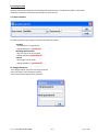
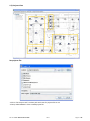
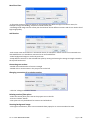
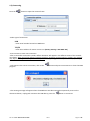
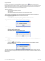
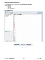
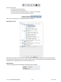
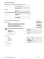
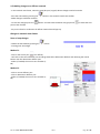
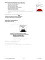
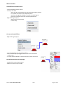
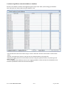
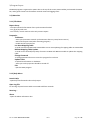
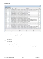
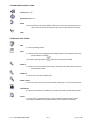
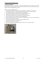
Rickard MLM PC Software User Manual User Manual and Instructions Introduction Rickard MLM PC based software is provided to enable viewing and easy manipulation of a network of Rickard VAV diffusers with MLM controls. The software can connect to the MLM diffuser network using a Master Communication Module or PC Set up kit (Including USB module) which are both provided with the software. The main program features are to give graphical representation of a diffuser network, to make changes to a diffuser network, and to log selected diffusers to a database to view in charts. Contents Rickard MLM PC Software User Manual ......................................................................................... 1 User Manual and Instructions ................................................................................................................ 1 Introduction ............................................................................................................................................ 1 Contents ............................................................................................................................................. 1 1) Getting Started ................................................................................................................................... 2 1.1) Access Control ............................................................................................................................ 2 1.2) Projects View .............................................................................................................................. 3 1.3) Connecting .................................................................................................................................. 5 1.4) Synchronize ................................................................................................................................ 6 1.5) Different views of Diffuser network .......................................................................................... 7 1.6) Making changes to a diffuser network ..................................................................................... 19 1.7) How to log diffuser network variables to a database................................................................ 22 2.1) Menu Bar .................................................................................................................................. 27 2.1.1) File Menu ........................................................................................................................... 27 2.1.2) Help Menu ......................................................................................................................... 27 2.1.3) Window Menu ................................................................................................................... 28 2.2) MLM Software Main Toolbar .................................................................................................. 31 2.3) Network view Toolbar .............................................................................................................. 31 3) How to install USB module drivers ................................................................................................. 32 3.1) Wizard Installation ............................................................................................................... 32 3.2) Manual Installation ............................................................................................................... 33 4) How to remove USB module drivers from windows ...................................................................... 34 5) How to setup PC to connect to Master Comms Unit ....................................................................... 35 6) How to change IP address on Master Comms Unit ......................................................................... 37 7) How to change Ethernet speed setup ............................................................................................... 38 8) Integration with other BMS network protocols ............................................................................... 39 9) MLM Controls – Fault diagnostic Procedure .................................................................................. 48 10) Diffuser unit views (See also: How to change between different diffuser views 1.5) .................. 50 11) Visual Elements of Diffuser network ............................................................................................ 51 12) Keyboard Shortcuts ....................................................................................................................... 52 13) Making changes to a diffuser network .......................................................................................... 52 14) Image file used for background of physical view .......................................................................... 53 15) How to create project background images .................................................................................... 55 16) How to create JPG image from DWG drawing ............................................................................. 56 17) Goods and Warranty ...................................................................................................................... 58 Part No. INST-RICKSOFTGUIDE 08/12 Page 1 of 58 1) Getting Started Run the LHA Systems setup.exe file and follow the instructions for automatic installation. Also follow automatic instructions to load the required drivers onto your PC. 1.1) Access Control On opening the bacs.exe program a password prompt will appear: Installer - No limitations on program use - Default password = password Building administrator - Only set points can be changed - Default password =password2 Viewer - No changes can be made - Default password = password3 To change password: - Start program with user level to change password - Go to file menu, select Change Password - Enter old password and the new password Part No. INST-RICKSOFTGUIDE 08/12 Page 2 of 58 1.2) Projects View Set projects file: - Click on "Set Projects File" to select path and name for projects file to use - Always make BACKUP's of the created project file Part No. INST-RICKSOFTGUIDE 08/12 Page 3 of 58 New Floor Plan: - A floor plan can be any big area which can be subdivided into different logical connection areas, for example in a high rise building, each floor could be a floor plan - The background image used for a floor plan should show all the different sections and do not need to be of high image quality. Add Section: - Each section area must relate to 1 connection device, for example 1 master comms unit connected to at most 60 diffusers or 1 USB device connected to at most 15 diffusers. - Select background image to use for Physical view - Setup different sections on the selected floor plan by moving and resizing the orange rectangle created in the top left hand corner. Connecting to a section: - Double click inside borders of section rectangle - Double click on section name in the project tree on the left Changing connection of an existing section: - Click the "Change Connection" button Deleting sections/floor plans: - Select the section/floor plan name in the project tree on the left - Press the "Delete" button - Floor plans can only be deleted if no sections are left defined Zooming background image: - Click right mouse button, select zoom commands from popup list or use mouse wheel to zoom Part No. INST-RICKSOFTGUIDE 08/12 Page 4 of 58 1.3) Connecting Press the button to open the connect frame. - Select type of connection: USB - Enter Serial number located on USB device TCP/IP - Enter the IP address of master comms unit (Factory Setting = 192.168.0.251) - Press Connect to start new connection - After a successful connection is made, diffuser elements will appear in the different views of the network view frame. Wait until all the different modules (interface, analogue and wall stat) are visible in the network view before starting with the synchronization process. This updating process may take a while, especially if wall stat modules are used. - To disconnect the current connection, click on the program. button and press on Disconnect or close the BACS - This warning message will appear when the USB device was disconnected unexpectedly. Press on the disconnect button, unplug and reconnect the USB device, press the Part No. INST-RICKSOFTGUIDE 08/12 button to reconnect Page 5 of 58 1.4) Synchronize To see the current status of a connected diffuser network, press the button to synchronize the graphical display with the diffuser network. The synchronization process will not start if changes to diffuser network still need to be saved. Due to the complexity of the diffuser network layout and the number of diffusers, the synchronization process may take a while to finish. - When to synchronize: - After connecting to a diffuser network - After resetting - After making changes to diffuser network or any synchronization errors -For an indication of the updating process see the graphical representation of the current number of messages queued in the Message Queue at the bottom of the screen. - Use the Node List view - Use the Log view - In the network view, the dynamic updating of diffuser variables can be seen. -Any synchronization errors found will be displayed with pop up dialogues -Possible causes: - Synchronization process started too soon after diffuser network reset. - Next step of action: - Check the network hardware setup - Reset network and restart synchronization process -Possible causes: - Master comms unit channel dead, no response from diffuser network when sending requests on channel. - Next step of action: - Check the network hardware setup - Click on the button and disconnect connection. Reconnect and reset diffuser network followed by a synchronize. - After the synchronization process finished the "Sync done" dialogue should appear. Diffusers with loop edges should appear in the Logical and Physical views. Any errors found in verification of diffuser network should pop up. Part No. INST-RICKSOFTGUIDE 08/12 Page 6 of 58 1.5) Different views of Diffuser network - 3 user views are available in network frame mode; physical, logical and network - Logged data views - Node list - Verify list - Chart View (See 1.7) 1.5.1) Network frame - Click on the tabs to switch between the network, logical and physical views Part No. INST-RICKSOFTGUIDE 08/12 Page 7 of 58 Use the view toolbar: - To start and stop editing mode - To change the current zoom level - To search in physical and logical view for a specific serial number - To verify the current state of the diffuser network Click on the channel buttons to deactivate specific channels Node Editor Panel After selecting a graph cell in one of the views, the Node Editor Panel (to the left of the screen) will display information that can be used to view or make changes. For each type of graph cell the following information will appear after collapsing the tree structure by clicking on it: Identification - Device id, giving the Serial Number and FW Revision number Part No. INST-RICKSOFTGUIDE 08/12 Page 8 of 58 Identification (continued) - Hardware id, giving the Product Code and HW Revision number - Host Id - Device Name, an unique name given to the device (up to 6 characters long) - Loop Number Process (For Interface modules (Type 10)) - Process cmd - Motor Man, to enable/disable motor manual mode - Heat Man, to enable/disable heater manual mode - Heat Enable, to enable/disable heater - Flow Enable, to enable/disable flow control - Motor Position giving values for Goto, Max, Min and Pos settings - Motor Goto - Motor goto setting - Motor Min - Motor minimum setting - Motor Max - Motor maximum setting - Interface Status - Heat - Heat Max - Motor Status - Heat State - Heater Out - Heat setting - Heater Max - Max setting Part No. INST-RICKSOFTGUIDE 08/12 Page 9 of 58 Process (For Analogue (Type 8) and Wall stat (Type 7) Modules) - Temperature - Space - CO - Set point - Set point 1 and Set point 2 setting - Temp Command - Sense, to enable/disable sensor - Change Over, to enable/disable change over - Set point 1, to enable/disable set point 1 - Set point 2, to enable/disable set point 2 - RTC - Time - Day of week - Back off time - Off - Back on time - On - Back off days - Day/Night/24h - Enable/disable days of week - Flow Address (only for analogue modules) - Type Part No. INST-RICKSOFTGUIDE 08/12 Page 10 of 58 Only for Wall stat (Type 7) Modules - Setup - Edit mode Tick the "Global" tick box to make changes to all graph cells of the same loop number or type. Use the Write button to make changes and the Read button to update the displayed information of a selected graph cell. Part No. INST-RICKSOFTGUIDE 08/12 Page 11 of 58 1.5.1.1) Physical View This view gives a graphical representation of the loop and zone relationships between the different diffusers on a diffuser network positioning each diffuser on a image background loaded using a project file. - Connecting to a diffuser network for the first time, all the diffusers in this view will be organized the same as the logical view. - After synchronizing and finding all the serial numbers, each diffuser will be positioned against the image background using the last position saved in the project file. - Using the edit mode, diffusers can be moved to new positions against the background image by left clicking on the diffuser and dragging it to a new position. Part No. INST-RICKSOFTGUIDE 08/12 Page 12 of 58 1.5.1.2) Logical View The logical view gives a graphical representation of the zone or loop relationships between the different diffusers on a diffuser network. TCP/IP connection There can be up to 4 active channels. Each channel can have up to 15 diffusers where each diffuser have a specific channel and loop number assigned to it. To connect diffusers on different channels, the Zone concept is used. There are 60 possible zones. Starting from the top, each row show all the diffusers in a zone, starting to the left with the master diffuser and continuing with all the slave diffusers. Zone zero starts at the top of the listing and all diffusers not forming part of a valid zone will be placed in a zone below continuing up to a row for zone 60 For example in Zone 6 the master diffuser with serial 08081984 on channel 4 and on loop 4 are connected to the following slave diffusers: - Diffuser with serial 08040708 on channel 3 and loop 4 - Diffuser with serial 07100444 on channel 2 and loop 6 - Diffuser with serial 09051919 on channel 1 and loop 6 Part No. INST-RICKSOFTGUIDE 08/12 Page 13 of 58 USB connection For a USB connection there is only one channel with 15 possible diffusers and only make use of the loop concept. Starting from the top each row consist of diffusers on the same loop, starting with diffusers on loop zero at the top (listing all the diffusers not forming part of a valid loop 1-15) continuing up to a row for loop 15. Each loop row will start from the left with the assigned master diffuser (if any) and continue to position the other diffusers in the loop by higher ranked id number. This view is ideal to group diffusers into different zones or loops or to make changes to an existing setup. Part No. INST-RICKSOFTGUIDE 08/12 Page 14 of 58 1.5.1.3) Network View This view gives a graphical display of the relationships between the interface, analogue and wall stat modules of a diffuser network. Starting from the top of the screen, all the different channels are listed apart from each other. For example, using a TCP/IP connection there may be more than one channel grouping while a USB connection will always have only one channel. - Each channel group consist of 3 columns: - The first column from the left listing all the interface modules from the top by id number, - The second column the analogue modules and after a successful synchronize the position will eflect the interface parent - The third column the wall stat modules and after a successful synchronize, the position will reflect the interface parent Part No. INST-RICKSOFTGUIDE 08/12 Page 15 of 58 1.5.2) Node list view When connected, all the different modules of the diffuser network will be listed, the information in each column dynamically updated when changes occur. How to view a diffuser with a certain serial number in physical and logical view - Select in node list the module with correct serial number - Right click mouse button and choose between - Show in physical view - Show in logical view - Close the node list to view the diffuser that was searched for Meaning of different type codes: - Type 7: Wall stat module - Type 8: Analogue module - ID, reassigned when resetting hardware - TC, type code = 8 - Serial Number - Product Code: BL21 - Sen - Co - SP 1 - SP 2 - Flow - Min - Type 10: Interface module-ID: - TC: - Serial No: - Product Code: - Heat/Cool - Heater: Manual - Motor: OC, Fault, Manual Part No. INST-RICKSOFTGUIDE 08/12 Page 16 of 58 1.5.3) Verify list view After synchronizing the diffuser network will be verified for any setup errors and it will be listed in this view. To show and update this view, press the button. To view diffuser with setup error: - Select row with valid serial number - Right click mouse button and select Show in physical/logical view - Minimize/close verify list view Part No. INST-RICKSOFTGUIDE 08/12 Page 17 of 58 1.5.3.1) Verify process of diffuser network After the synchronization process is finished, the diffuser network is verified for the following error or warning conditions. - Diffusers not part of a loop - Conflicting setup for analogue and wall stat connected to diffuser - No space temperature enabled for loop - More than one space temperature enabled for loop - No set point enabled for loop - More than one set point enabled for loop - More than one change over enabled for loop - Nodes not updated - Unresolved host issues - Loop Different - Name Different - Command Different - Set point 1,2 Different - Back off DN Different - Backoff24 Different - Time off Different - Time on Different - Motor Min Different - Motor Max Different - Diffuser in manual mode - Motor Fault - Over Current Part No. INST-RICKSOFTGUIDE 08/12 Page 18 of 58 1.6) Making changes to a diffuser network - In the network view frame, select the view (Physical, Logical) where changes need to be made. button in the network view frame toolbar. - Start the edit mode by pressing the - Make changes to diffuser network - To save the changes press the process has finished button. and wait until the button has greyed out to show that save - Any errors found in verification of diffuser network should pop up. Changes in network view frames Zone or loop changes - Enable the edit mode by pressing the button - Creating new zone edges Method 1: - Click on the source port of a diffuser, - Left click on the source diffuser port and drag towards the destination diffuser and releasing the mouse button over the destination diffuser port - Select (if needed) the correct zone number (160) Method 2: - Click on source diffuser port - Click on destination diffuser port - Select (if needed) the correct zone number (160) Part No. INST-RICKSOFTGUIDE 08/12 Page 19 of 58 -Adding an unconnected diffuser unit in its own zone - Click at the top of the diffuser unit on the self zone - select the correct zone number - deleting existing zone edges - Select the zone edge to delete - Press the delete button on the keyboard - Renaming existing zone edges - Double click on a zone number - Select in the drop down the correct zone number - WARNING: any other zone edges with the same zone number will also be changed -Moving diffusers around in the physical view button - Enable the edit mode by pressing the - Left click and drag diffuser unit to new location -Master Diffuser set point change - Double click on a master diffuser unit - Change the set point value A Master Diffuser Unit is defined as: -diffuser with an analogue and wall stat module -In the image above, the following can be determined: Analogue (On Board Controller) - not enabled (0.0°C is greyed out) Wall stat - Enabled - Temperature reading 17.8 in degrees Celsius - Set point: 22 in degrees Celsius -Expanding or collapsing Diffuser units - Select the diffuser unit by clicking on it - Press right mouse button to expand or collapse current selected diffuser view Part No. INST-RICKSOFTGUIDE 08/12 Page 20 of 58 Mouse Interface In the different network views - The mouse wheel can be used to - Scroll up and down - Zoom in and out by holding in the Ctrl key while logical, physical or network view have current keyboard focus - Scroll left and right by holding in the Shift key while logical, physical or network view have current keyboard focus - Right click to get pop up - Select zoom in/out/normal - Launch help Current selected diffuser - Right click to get pop up - To expand/collapse the view of the diffuser - Click on 'Show in physical/logical view' to view selected diffuser in other view - To zoom selected diffuser to normal zoom level, click on zoom in Current focused zone or loop edge - Double click to get rename pop up - Select new zone or loop number Part No. INST-RICKSOFTGUIDE 08/12 Page 21 of 58 1.7) How to log diffuser network variables to a database Connect to the diffuser network to be logged using the project view. After synchronizing go to Window menu and open the "Select nodes to log in database" view. - Tick the tick boxes next to the nodes to log or use the "Select All" tick box at the bottom to select all the nodes - Click the "Save Selection" button to save the current selected nodes to the project file - Change the Logging interval from the default 3 minutes using the up/down arrows or by entering a new value in seconds - To start logging to the database, tick once the "Logging Enabled" tick box and wait for the database to be created or opened after which the tick mark will appear Part No. INST-RICKSOFTGUIDE 08/12 Page 22 of 58 How to show logged information in Chart view Select the diffuser in the logical or physical view to show in Chart view: - Right click and select "Show in Chart" in the popup dialogue - The selected diffuser serial numbers of all the modules will appear in the Chart view - Multiple diffusers can be selected in this way to compare network variables between different diffusers in the Chart view - Go to Window menu and select "Chart view" Output format Tick the "Show Chart" tick box to show the output in a chart form OR Tick the "Export" tick box to redirect output to a tab delimited text file - Click the Browse button, - Select the folder to save the export text file - Enter a name for the text file - Finish by clicking on the open button - The name and path to the text export file should now appear in the edit box next to the Browse button - This edit box can also be manually edited, however no valid file and path checking will be done Part No. INST-RICKSOFTGUIDE 08/12 Page 23 of 58 FROM Select Modules Beneath the "From" heading select the different modules of the diffuser to show in chart or export - Tick the Interface tick box - Under the "SELECT" heading put ticks next to the following network variables to view or export - Motor Min, Motor Max, Motor Goto, Motor Pos, Heater Max, Heater Out - Tick the Controller tick box - Under the "SELECT" heading put ticks next to the following network variables to view or export - Space Temp, Co Temp, Sp1, Sp2, Active Sp, Flow - Tick the Event tick box to view or export the following events - Motor Fault - Over current - Reset WHERE Set Start and End time - Select the digit to change with mouse click and use spin controls to change or enter manually the correct value - By default the Start time will be 24 hours back from the current time - Tick "End time now" to get output up to the current time Serial numbers of selected diffusers Beneath the "End time now" tick box the selected diffusers serial numbers will be located for each module. By default all the serials will be selected. To unselect/reselect specific serials, press and hold the Ctrl button and click on the serial number to change. Use of "All Serials" tick box Tick the "All Serials" tick box to disable the current selected serial numbers and select all existing serials in database. It can be used to export the whole database to a tab delimited text file for all existing serials in the database. Clear all tick boxes, serial number fields Use the "Clear" button to clear all the selected tick box fields and remove all the selected serials. Use of Status tick box Part No. INST-RICKSOFTGUIDE 08/12 Page 24 of 58 For the Interface and Controller module there is a status network variable that is a word value. Each of the bits in the word value relate to the following states that can be set. - Use the AND/OR bit operator to include and exclude the selected states How to understand Chart view - Start at the bottom of the chart by looking at the different colour and shape schemes of the selected network variables - The Domain-axis start from the left with the entered "Start time" Date Timestamp and continue up to the "End time" Date Timestamp - The Range-axis of the different network variables is located to the left and right of the chart - Hover the mouse curser over plot points to display the specific network variable, Date Timestamp and Range value in a popup Part No. INST-RICKSOFTGUIDE 08/12 Page 25 of 58 Right click in the general chart area: - Select Properties..., to change chart specific properties - Select Save as..., to save the current chart view to a PNG image - Select Print.., to print the current chart - Select Zoom in, Zoom Out and Auto Range Part No. INST-RICKSOFTGUIDE 08/12 Page 26 of 58 2) Program Layout The BACS program is organized in a Menu bar at the top of the screen, Main Toolbar just beneath the Menu bar, and a general view area for Diffuser network views and logging views. 2.1) Menu Bar 2.1.1) File Menu Export Setup - To export network information after synchronization finished - To a jpg of physical view - To a text file, use tick mark to select only masters export Properties Tick boxes: - Auto Sync (automatic network synchronization after any reset/connect event) - Start with Projects View (when executing program) - Enable Grid in Physical View Lon Auto Mapping Table To send command to MCU with LON module to start auto updating of mapping table on LON module BACnet Mapping Table Update To send current channel/loop setup of masters to MCU with BACnet module to update the mapping table Change Password To change password for access control to program for each user Update Flash To upload new firmware on hardware - Auto Sync under properties should be turned off Exit - Quit the BACS program 2.1.2) Help Menu Launch Help - Open help interface with index to help topics Open Log File To view log of special events while connected to diffuser network Save Log... About - Open the About information box Part No. INST-RICKSOFTGUIDE 08/12 Page 27 of 58 How to use help The context-sensitive help system can be activated in the following ways: Window Level - Press F1 (or Help) key, get help for window with current focus Field-Level - Activate field-level help by pressing help icon button in main toolbar -Navigate with mouse or keyboard and select object to get help on Help Menu Item - In the menu bar, go to Help and select Contents 2.1.3) Window Menu 2.1.3.1) Network view - Tab support for Network, Logical and Physical views (See 1.5.1.1 to 1.5.1.3) Part No. INST-RICKSOFTGUIDE 08/12 Page 28 of 58 2.1.3.2) Log view -Tabs Scroll Lock - to stop auto scrolling to new logged messages Clear Buffer - clear existing logged messages -Columns CH - channel FC - function code -Loop TC - type code -ID Len - data length -Data CRC - code redundancy check Message - description of logged data -Time -Filter-enter channel, function code, loop number, type code and id to filter displayed log data Part No. INST-RICKSOFTGUIDE 08/12 Page 29 of 58 2.1.3.3) Node list (See 1.5.2) 2.1.3.4) Verify Error List (See 1.5.3) 2.1.3.5) Select nodes to log in database (See 1.5.4) 2.1.3.6) Chart View (See 1.5.4) Part No. INST-RICKSOFTGUIDE 08/12 Page 30 of 58 2.2) MLM Software Main Toolbar Connect (See 1.3) Synchronize (See 1.4) Reset - Press the button to reset the diffuser network. To reset only the Master Comms Unit, press the disconnect button in the connect frame while connected Help 2.3) Network view Toolbar Edit - To start an editing session. Save - To start the process of propagating the changes made in the network view to the physical diffuser network. - The button will be greyed out when the save process finished Zoom in - To zoom into current network view frame, used when the mouse does not have a mouse wheel button. Zoom out - To zoom out of current network view Zoom normal - To return to the normal 1:1 zoom level after zooming in or out of a network view frame. Find Diffuser - To zoom into and focus on a diffuser in current view with entered serial number. Verify - To verify after a synchronize that the current diffuser network setup is valid. - The button is disabled until synchronization process finished successfully Part No. INST-RICKSOFTGUIDE 08/12 Page 31 of 58 3) How to install USB module drivers 3.1) Wizard Installation The USB module allows easy connection to a network of 15 MLM diffusers. The USB module can connect anywhere into the network using a standard slave cable with microfit connectors. Follow the procedure below to connect the USB module to your PC. Software set-up and loading of drivers: Copy the Rickard MLM software folder into the “Programs Files” folder on your PC’s C drive. The USB module connects to a PC using a USB cable. Plug the cable into any open USB port. The “Found New Hardware” wizard should start up automatically. The wizard will firstly look for a driver for the LHA USB Composite Device. Choose the second option to install from a list or specific location. Don’t allow the wizard to search. You will point it to the correct location. Point the wizard to the drivers folder in the Rickard MLM folder. Allow the wizard to install the driver. (The driver is not digitally signed but you can continue anyway.) Click Finish after the driver is installed. The software will now look for a driver for the “BACS USB Controller” Follow same procedure as for previous device. Click Finish after the driver is installed. The PC should display a message indicating that the drivers are successfully installed Part No. INST-RICKSOFTGUIDE 08/12 Page 32 of 58 3.2) Manual Installation Version 1 driver install (MLM application v1) - Browse to Program Files\LHA Systems\BACS\Driver\ directory - Run BACS_USB_Driver.exe, (no popup indication that driver was installed) - Open Control Panel and open Add or remove Programs - Press F5 to refresh display of installed programs - Scroll down to LHA Systems BACS USB Driver (Driver removal) to verify driver v1 installation Version 2 driver install (MLM application v2 - v4) - Browse to Program Files\Rickard Air\MLM Application\Driver\ directory - Run BACSUsbDriverV2Install.exe - Open Control Panel and open Add or remove Programs - Press F5 to refresh display of installed programs - Scroll down to LHA Systems BACS Device Driver V2 (Driver removal) to verify driver v2 installation Part No. INST-RICKSOFTGUIDE 08/12 Page 33 of 58 4) How to remove USB module drivers from windows - Open Control Panel and open Add or Remove Programs - Scroll down to LHA Systems.... Version 1 driver removal (MLM application v1) - Select LHA Systems BACS USB Driver (Driver removal) and click on Change/Remove button to uninstall driver Version 2 driver removal (MLM application v2 - v4) - Select LHA Systems BACS Device Driver V2 (Driver removal) and click on Change/Remove button to uninstall driver Part No. INST-RICKSOFTGUIDE 08/12 Page 34 of 58 5) How to setup PC to connect to Master Comms Unit Connect the PC directly to the Master Comms Unit by using a crossover cable with the following colour coding scheme Crossover Ethernet cable If connecting a PC to a Master Comms Unit through a switch or hub a normal straight-through cable can be used Straight-through Ethernet cable TCP/IP static address setup on Windows PC - Open Control Panel and double click on Network Connections - Right click on Local Area Connection and select Properties - Scroll down and select Internet Protocol (TCP/IP) on XP PC or TCP/IPv4 on Vista PC Part No. INST-RICKSOFTGUIDE 08/12 Page 35 of 58 - click on properties - IP address: enter an IP address different from any IP address already used on Ethernet network - Subnet mask: 255.255.255.0 - Default Gateway: for example 192.168.0.1 - Click on Ok button - Also change the IP address of Master Comms Unit from default 192.168.0.251 to an unique address on the network Part No. INST-RICKSOFTGUIDE 08/12 Page 36 of 58 6) How to change IP address on Master Comms Unit - Open a web browser and enter the IP address in the address bar (factory setting: http://192.168.0.251/ ) - Click on Configure LAN interface Part No. INST-RICKSOFTGUIDE 08/12 Page 37 of 58 In IP address field enter new IP address: - Click on Save changes button Within a period of 3 minutes - Enter in web browser address bar the new IP address and press enter - Click again on Configure LAN Interface - Click on the Modify/validate settings button to make the IP address changes permanent If last 3 steps fail: re-enter the initial IP address in the web browser address bar and start all over again. 7) How to change Ethernet speed setup - It is recommended not to use Auto-negotiate due to some routers that are incompatible with this setting turned on. - Open a web browser and enter the IP address in the address bar (factory setting: http://192.168.0.251/ ) - Click on Configure LAN interface - Select the Ethernet speed tick box, for example 100M - Click on the Modify/validate settings button - Click on Save Changes - Click on Go back to menu page button at the bottom of the page - Click again on Configure LAN interface. The Settings validated tick box will not be ticked. - Click again on the Modify/validate settings button and the Settings validated tick box will be set again Part No. INST-RICKSOFTGUIDE 08/12 Page 38 of 58 8) Integration with other BMS network protocols The following network variables of the MLM Proprietary network are visible to other BMS network protocols like BACnet and LONtalk. - Space temperature - Temperature Set point - Heater output temperature - Diffuser plate motor position - Heating or Cooling mode - Change Over Sensor (Supply air temperature) Mapping and binding of network variables to other network protocols Master Diffuser concept On the MLM Proprietary network there can be up to 60 diffusers installed on 4 different channels, each channel with a maximum of 15 different diffusers. They can be arranged in zones where each zone have one master diffuser that control the other slave diffusers. For example, in the layout Zone 6. Diffuser with serial 08081984 and on channel 4 and loop 4 is set as the master and control the slave diffusers with serials 08040708,07100444,09051919. Therefore it is only necessary to do a mapping of all the masters on the MLM proprietary network to another BMS network protocol by using the channel and loop number as reference. Part No. INST-RICKSOFTGUIDE 08/12 Page 39 of 58 Mapping Table Setup By using the MLM application File/Export Setup command, a list can be exported to a tab delimited text file of all the master diffusers on the MLM proprietary network. Connection Address: 192.168.0.251 Master Comms Device ID: 04CC68C40201 Exporting only masters Channel Type 1 2 3 4 Interf Interf Interf Interf ID HID 5 2 15 4 5 2 15 4 Loop ChLpMap LonStr Zone Code Serial Nr 5 2 15 4 21 34 62 68 [1] 5 [2] 2 [3] 14 [4] 4 20 18 25 6 BL20 BL20 BL20 BL20 09051918 07100447 08030009 08081984 Firmw Device Name 01.24 01.24 01.24 01.24 Using the ChLpMap and LonStr columns a mapping table can be build up String [1] 5 [2] 2 [3] 14 [4] 4 Decimal 21 34 62 67 Depending on which protocol is used a String or Decimal presentation of the channel and loop number may be needed to setup the mapping table Table 1 Part No. INST-RICKSOFTGUIDE 08/12 Page 40 of 58 MCU Lon module setup Part No. INST-RICKSOFTGUIDE 08/12 Page 41 of 58 There are 38 functional blocks in the functional profile of the MCU Lon module that can be setup to bind with 38 master diffuser units on the MLM Proprietary network. The nciChLpMap configuration property string value (for example [2] 3) can be changed from the default value by using network tools like LONmaker. The nviChLpMap network variable that use a decimal value (see Table 1) of the channel/loop binding may also be used with networks tools. Automatic mapping table update With the latest Master Comms Unit with LON module the mapping table can also be automatically updated using the following procedure: 1. Insert different channels into MCU 2. After final commissioning, switch off MCU and switch on again 3. Wait for 1-2minutes for all temperature pdo's to be routed through to LON module 4. Press service pin on LON module 5. For the next 3 minutes, WAITE 6. In 3 minutes, new mapping table will be build 7. After 3 minutes, new mapping table will be written into nviChlpMap1-38 and nciChLpmap1-38 8. First 38 masters will be mapped, above 38 will be ignored and must be manually switched with first 38 channel/loop mappings using LON commissioning tool. 9. This need only to be done once to setup channel/loop mapping 10. Use LONmaker/Honeywell commissioning tools 11. To update serial string field, wink device. 12. For the next 1.5 minutes serial numbers will be updated for each valid Channel/Loop mapping 13. When changing any channel/loop mapping, all the serial number fields will reset, use wink to update serial fields again. Part No. INST-RICKSOFTGUIDE 08/12 Page 42 of 58 MCU BACnet module setup Using a BACnet commissioning tool one can see a list of all the objects and their properties on the MCU BACnet device. These objects can be setup to bind with 20 master diffuser units on the MLM Proprietary network and are organized in the following layout of the Analogue Input, Analogue Output and Multistate Output objects. A Device Object with device properties Look in the object-identifier property for the device instance number, 2355375. It relates to the MCU BACnet device MAC-address that one can view entering the IP address in a web browser and going to the LAN configuration page. Part No. INST-RICKSOFTGUIDE 08/12 Page 43 of 58 Open the windows calculator program under accessories and enter in hex the MAC address: -50c2a3f0af -Switch the calculator to binary mode to get 101000011000010101000111111000010101111 -Count the first 22 bits from the right and copy back into the calculator and switch to decimal to get the instance number 2355375 20 Analogue Inputs with description Supply Temp 20 Analogue Inputs with description Control Disk pos Part No. INST-RICKSOFTGUIDE 08/12 Page 44 of 58 20 Analogue Inputs with description Heater 20 Analogue Inputs with description Space Temp Part No. INST-RICKSOFTGUIDE 08/12 Page 45 of 58 20 Analogue Outputs with description Set point 20 Multistate Outputs 1-20 with description Mode Part No. INST-RICKSOFTGUIDE 08/12 Page 46 of 58 20 Multistate Outputs 1-20 with description Bind Map Taking the first entry in the array of 20 Supply Temp, Control Disk pos, Heater, Space Temp, Set point, Mode and Bind Map, together form a functional block and the same with the other items in the array structures. Each of these functional blocks are bind to a potential master diffuser unit on the MLM Proprietary network by the channel loop decimal value specified in the Multistate output Bind Map object present value property. Taking the first functional block as example: - Supply Temp 1 - Control Disk pos 1 - Heater 1 - Space Temp 1 - Set point 1 - Mode 1 Bind map 1 = 17 Use Table 1 to find channel = 1 and loop = 1 from 17 decimal value. Therefore all these variables will get their specific values from the master diffuser unit on channel 1, loop 1 How to setup Bind map values automatically using MLM application After commissioning all the diffusers on the network, goto File and select "BACnet mapping table update" to send to the MCU BACnet device the first 20 masters and change the Bind map values to the correct decimal values. Part No. INST-RICKSOFTGUIDE 08/12 Page 47 of 58 9) MLM Controls – Fault diagnostic Procedure Fault detection MLM Interface Power Supply Fault Symptoms Possible Cause Fix Red LED constantly on Interface flash program upload unsuccessful Processor in undefined state Red LED off No power to the Interface unit due to cabling error No Wall Stat or Analogue module installed. These units initiate the data communication Retry upload up to 3 times. If not successful replace. Power off and on. If not successful replace. See item ‘Cable verification’ below. LED on PSU, visible through side vent, is constantly Faulty Power Supply Unit 1) Verify that at least one Wall Stat or one Analogue module is installed per Power Supply. 2) Cabling error to Wall Stat unit. See item ‘Cable verification’ below. See item ‘Power Supply’ Short circuit between V+ and 1) Verify cabling GND 2) Unplug MLM interface units until the fault is isolated Replace Replace Check mains feed voltage and connection Remove excessive nodes off. Wall Stat LED on PSU is cycling. Faulty Power Supply Faulty Power Supply Low input voltage Cycles continuously between Revision and temperature on the LCD More than 15 MLM Interface nodes installed on the bus Faulty Wall Stat cabling Faulty MLM Interface connected to the Wall Stat Faulty Wall Stat Displays temperature only on the LCD MLM Interface unit not operational MLM Interface in flash program loader mode Faulty Wall Stat cabling No display on wall Stat LCD No Power to Wall Stat Wall Stat unit faulty Part No. INST-RICKSOFTGUIDE 08/12 See item ‘Cable verification’ below. Replace Replace See MLM Interface diagnostics See MLM Interface diagnostics See item ‘Cable verification’ below. See item ‘Cable verification’ below. Replace Page 48 of 58 MLM Controls – Fault diagnostic Procedure (continued) Motor actuator drive Motor noisily grinding against an end stop, top or bottom. Premature end stop detection due to more than 8 diffuser nodes connected to a single Power Supply connection point Faulty slave cabling Motor not moving (verify with ‘motor manual’ command in BACS application) Motor harness flat cable Motor slow and jerky movement Motor erratic movement up and down – in tandem with other diffusers Cable verification Wall Stat (RJ12) cable Slave cable – 3 core 20AWG to 4-pole Microfit connector unplugged on the MLM Interface box Motor harness cable faulty Motor faulty Low voltage to motor Motor harness cable faulty Motor faulty More than one temperature and/or set point is selected for one control zone (room area) Temperature sensor unplugged or faulty Cable not plugged in properly Connector plug connection point damaged due to installation Cable damaged due to installation Cable not plugged in properly Connector not inserted correctly Cable core pulled back on the pin Part No. INST-RICKSOFTGUIDE 08/12 1) Re-arrange Power Supply placement 2) Upload rev 1.16 or later power management flash program to MLM Interface See item ‘Cable verification’ below. Secure Replace cable Replace motor See item ‘Cable verification’ below Replace cable Replace motor Access the control zone with the BACS application and unselect the superfluous set point/temperature parameters Secure or replace Secure Test and replace Test and replace Secure Verify the connector polarity with the latch towards the top Replace Page 49 of 58 10) Diffuser unit views (See also: How to change between different diffuser views 1.5) Expanded View Collapsed View Master Diffuser Black Diffuser: initializing Blue Diffuser: cooling Red Diffuser: heating Yellow Diffuser: manual mode White Diffuser: idle/deadband Part No. INST-RICKSOFTGUIDE 08/12 Page 50 of 58 11) Visual Elements of Diffuser network - Diffuser Unit - Interface module - Analogue module - Wall stat module - Port - Grouping - Zone edges - Loop edges - Errors - Motor fault - Over current Part No. INST-RICKSOFTGUIDE 08/12 Page 51 of 58 12) Keyboard Shortcuts - F1, to bring up Help window - Delete button, deleting selected loop, zone edge or project section 13) Making changes to a diffuser network - In the network view frame, select the view (Physical, Logical) where changes need to be made. button in the network view frame toolbar. - Start the edit mode by pressing the - Make changes to diffuser network (See 1.6) - To save the changes press the button. - Wait until the button has greyed out to show that save process has finished - Any errors found in verification of diffuser network should pop up. (See 1.5.3) Part No. INST-RICKSOFTGUIDE 08/12 Page 52 of 58 14) Image file used for background of physical view In the physical view the selected image for a project section will be loaded as the background. When creating the image jpg, squares of dimensions 100x100 pixels can be drawn as placeholders where collapsed diffuser views can be moved to when viewing an existing diffuser network. Part No. INST-RICKSOFTGUIDE 08/12 Page 53 of 58 What detail should appear on a background image for each section -It should be a 2d presentation (viewed from the top) of all the diffuser locations in a section area -All the diffusers should share the same connection -up to 15 diffusers for a USB connection -up to 60 diffusers for a TCP/IP connection -also read step 5 below, how to select only relevant parts of a larger jpg image Part No. INST-RICKSOFTGUIDE 08/12 Page 54 of 58 15) How to create project background images 1. Image format used: jpg 2. Maximum image dimensions: (4000 x 4000) pixels -Any image used in project view should not have bigger dimensions than 4000x4000 pixels. For example, 3100x4500, 3000x5500 should be fine. -Very big dimensions like 7000x6000 have memory constraints that will make it unusable. 3. How to check image dimensions -open windows explorer and select jpg image -right click and select properties at the bottom -click on Summary tab at the top and press the Advanced button at the bottom if needed -take note of the width and height value in pixels 4. How to insert diffuser placeholders with dimensions 100x100 in existing jpg image -open jpg image with Microsoft Paint program (found under Start, All Programs, Accessories) or any other image editing program. -start a 2nd Paint program instance and start with a new, blank image -select Image, Attributes and enter Width: 100, Height 100 using Pixel Units -Press Ok button -Now an image rectangle with dimensions 100x100 is created -Change white background to different colour or any other pixel pattern using drawing tools -save image to use next time placeholder image needs to be inserted in an existing image -press Edit, Select All -press Edit, Copy -switch back to 1st opened image -press Edit, Paste -if Edit, Paste is greyed out, make certain that both steps Edit, Select All and Edit, Copy was followed properly. -in the top left hand corner of the image a 100x100 selection area will be copied -left click inside created selection area, not releasing button and drag the selection to correct position on image background. If the visible area does not include the proper location, drag selection to the visible area edge, release mouse button, use scroll bars to make invisible parts visible, reselect selection and start drag process again. -use Edit, Undo to delete last changes -repeat insert process starting with Edit, Paste -save the changed image, using a different name if needed 5. How to select parts of a too large jpg image file -open image in image editing program, for example paint shop pro, coral draw, irfanviewer etc. -Don't use Microsoft paint program due to limited selection capabilities (no auto scrolling when dragging selection area) -use selection tool to break down big image into smaller images. Keep in mind that it should fit in an area with dimensions of 4000 x 4000 pixels 6. How to rescale jpg image -open image with image editing program, for example Microsoft Paint -press Image, Stretch/Skew -Enter under Stretch, Horizontal and Vertical percentage value, for example 50%, 110% to rescale whole image -DON'T rescale an already large image much bigger, your pc will run out of memory and slow down dramatically. -save rescaled image 7. Also read How to create JPG from DWG drawing Part No. INST-RICKSOFTGUIDE 08/12 Page 55 of 58 16) How to create JPG image from DWG drawing 1. Use AutoCAD or Download free Autodesk viewer program DWG True View 2008 (http://www.download.com/DWGTrueView/3000-6677_410690117.html) 2. Open drawing 3. Go to File, Plot... 4. Select under Printer/Plotter Name: dropdown "PublishToWebJPG.pc3" 5. Click Properties button next to PublishToWebJPG.pc3 6. Under User-defined Paper sizes & Calibration, select Custom Paper Sizes 7. Press Add... button 8. Select Start from scratch, click next 9. Enter in Width and Height field 4000 and keep unit on pixels 10. Click next, and next, finish 11. Click on Ok button to close Plotter Configuration Editor dialogue 12. In the Plot -Model dialogue, select in Paper size dropdown the newly created paper size 4000.00 x 4000.00 pixels .Other paper sizes could also be entered, for example 3000.00 x 5000.00, 2000.00 x 6000.00 etc 13. Under Plot area heading select under What to plot: Window 14. Tick center the plot and fit to paper settings 15. Click on Window< button Part No. INST-RICKSOFTGUIDE 08/12 Page 56 of 58 16. The screen will flip to model view 17. Zoom in with mouse wheel, hold mouse wheel pressed to pan around in drawing area 18. Click left mouse button at correct snap point (for example top left corner of floor outside wall) to select top left corner of print area 19. Zoom/pan to and click left mouse button again to select bottom right corner of print area (for example bottom right corner of floor outside wall) 20. The screen will flip back to Plot - model dialogue, press ok button (or Preview... button first to see the result) 21. Browse to save directory, enter file name to save too and click on save button 22. Test if created JPG is useful - Each diffuser placeholder on dwg drawing should relate to +- 100x100 pixels on captured jpg - If too big, use paper sizes other than 4000x4000 to better fit your floor plan area - If too small, make certain that only relevant detail relating to diffuser positions are displayed on jpg image. Therefore don't capture irrelevant data like the drawing information details normally to the right of the drawing area - Also make changes to original dwg, for example make serial number text font bigger, lines thicker, change colours, etc. Part No. INST-RICKSOFTGUIDE 08/12 Page 57 of 58 17) Goods and Warranty Part No. INST-RICKSOFTGUIDE 08/12 Page 58 of 58