1
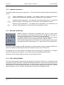
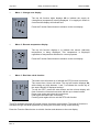
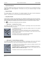
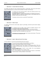
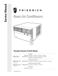
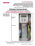
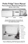
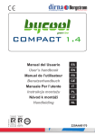
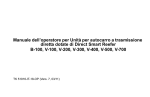
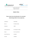
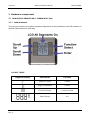
July 2010
MLM_24 Reference Manual
LHA SYSTEMS
3. Hardware components
3.1 MLM DIGITAL REMOTE WALL THERMOSTAT (WS)
3.1.1 USER INTERFACE
The user has access to the system setup and diagnostics via the pushbutton and LCD interface on
the Wall Thermostat Unit (wall-stat).
LCD KEY TABLE
Segment Display
BT0070
Rev: A
Description
Function
Degrees Celsius
Control
Degrees Fahrenheit
Control
Function Display
Control/General
Main Display
All
General Release
PAGE 10
July 2010
MLM_24 Reference Manual
Icon Display
BT0070
Rev: A
LHA SYSTEMS
Description
Function
Liter per second
Air volume
Cubic feet per min
Air volume
Battery Low
Diagnostics
Setup
Commissioning
Setpoint
Control
Cooling mode
Control
Heating mode
Control
Real time clock
Back-off timer
Wireless connect
Connection
Air flow detect/limit
Air volume
Heater on
Control
End-stop open/close
Control
Moving towards close
Control
Actuator not moving
Control
Moving towards open
Control
Percentage display
Control
General Release
PAGE 11
July 2010
MLM_24 Reference Manual
LHA SYSTEMS
3.1.2 TEMPERATURE DISPLAY
The default display shows room temperature. The top left function display shows the temperature
source:
Control temperature not selected – the display shows the space temperature
measured by the wall-stat. No temperature is selected for control purposes.
Onboard Control temperature – the display shows onboard temperature, as measured
inside the diffuser. This temperature is used for the room temperature control.
Remote Control temperature – the display shows temperature, as measured by the
wall-stat. This temperature is used for the room temperature control.
3.1.3 SETPOINT SELECTION
Setpoint selection is achieved by pressing either the up or down arrow
button momentarily. The buzzer will sound once, the SP icon will switch on
and the current setpoint value will show on the digital display.
The default value is 22°C (71ºF). The top left fun ction digits will indicate
respectively the source of the setpoint and which setpoint is active.
If the function display shows r1, it indicates the ‘remote setpoint’ (wall-stat) is
the temperature source and setpoint 1, ie. ‘normal control’ is currently active.
Should the function digits show o2 it indicates an onboard-master controller (inside the diffuser) is
where the setpoint is activated and the back-off setpoint is active at the current time.
By pressing the up or down buttons the setpoint value will increment or decrement in 0.5 degree
intervals. Please note only setpoint 1, for normal control can be edited by this function.
Pressing the enter button (right bottom) will exit the setpoint function.
3.1.4 STEP THROUGH MENU
The user has the option to step through the diagnostic and manual control menu. Pressing the right
top button (Function Select) for 5 seconds will activate this feature. The buzzer will sound once and
the display will advance to the next function. To exit this mode, the user must press the Function
Select button for 5 seconds before the buzzer will sound and the display will revert to the (default)
space temperature value. The Step Through Menu will select the following functions:
BT0070
Rev: A
General Release
PAGE 12
July 2010
•
MLM_24 Reference Manual
LHA SYSTEMS
Menu 1 - Change-over display
The top left function digits displays CO to indicate the supply air
(changeover) temperature is being displayed. If no supply air sensor is
connected the display will indicate zero.
Press the Function Select button to advance to the next display.
•
Menu 2 - Remote temperature display
The top left function displays r to indicate the remote (wall-stat)
temperature is being displayed. This temperature is displayed
regardless of temperature selection for control purposes.
Press the Function Select button to advance to the next display.
•
Menu 3 - Real time clock function
The watch icon will switch on to indicate the RTC function is selected.
The current time, hh:mm will show. The top left function displays dx,
with x being any digit between 1 and 7 to indicate the current day of
the week. Monday is displayed as day 1.
To edit the RTC, press the enter button and the minute display will
flash. Select the current minute value with the up or down buttons.
Press enter again and select the current hour.
Enter again and select the current day.
Pressing enter again will now exit the RTC edit function.
The RTC facilitates the back-off control function for energy conservation. The back-off function is
activated through the MLM Application by setting the SP2 value during commissioning.
Press the Function Select button to exit this function and advance to the next display.
BT0070
Rev: A
General Release
PAGE 13
July 2010
•
MLM_24 Reference Manual
LHA SYSTEMS
Edit Mode
The edit mode allows extended setup features through the wall-stat. The edit mode is enabled
through the MLM Application by selecting the wall-stat box in the Network screen as indicated.
Selecting the Setup Tab opens the Edit Mode select tick box:
BT0070
Rev: A
General Release
PAGE 14
July 2010
•
MLM_24 Reference Manual
LHA SYSTEMS
Setpoint Edit Disable
This feature disables the setpoint from being altered on the wall-stat unit. The setpoint can still be
edited through the MLM Application. This feature can only be activated through the MLM
Application.
•
Setpoint Display
The default display on the wall-stat is for setpoint instead of the space (control) temperature
display. This feature can only be activated through the MLM Application.
•
Setup Menu Enable
If this function is selected, the step-through menu enables the following setup sub-menu features.
These features will follow directly after the Real-time-clock function indicated above. Please note
that these setting will be applied to all the diffusers connected in a control zone, master or slave.
The
icon will show to indicate this sub-menu selection.
Sub menu 1 - Actuator Drive Control
The display will show the current control disk position in percentage, with the top left function
display indicating dr for motor drive.
To manually drive the disk, press the up/down arrows for the required
position and press enter.
The double bar icon will flash to indicate the motor is manually controlled.
Verify the disk movement of all the diffusers in that control zone and the
position display update.
To advance to the next menu, press the Function button.
The control will revert back to automatic mode.
Sub menu 2 – Control disk open end-stop
The display will show the open end-stop disk position in percentage, with the top left function
display indicating dr. The down arrow and single bar will flash to indicate ‘open end-stop’
To change the open end-stop position, press the up/down arrows for the
required position and press enter.
The display will flash --- until the new parameter is accepted by the system.
Should the disk be outside the end-stop range it will manually drive the
diffusers in that control zone into range.
To advance to the next menu, press the Function button.
BT0070
Rev: A
General Release
PAGE 15
July 2010
MLM_24 Reference Manual
LHA SYSTEMS
Sub menu 3 – Control disk close end-stop
The display will show the close end-stop disk position in percentage, with the top left function
display indicating dr. The up arrow and bar will flash to indicate ‘close end-stop’
To change the close end-stop position, press the up/down arrows for the
required position and press enter.
The display will flash --- until the new parameter is accepted by the system.
Should the disk be outside the end-stop range it will manually drive the
diffusers in that control zone into range.
To advance to the next menu, press the Function button.
Sub menu 4 – Heater output
The display will show the current heater output in percentage, with the top left function display
indicating Ht.
To manually drive the heater output, press the up/down arrows for the
required percentage output and press enter.
The heater icon will flash to indicate the heater is manually controlled.
The character display will indicate zero until the new value is accepted and
the heater in that zone controlled to the new value.
To advance to the next menu, press the Function select button. The control
will revert back to automatic mode.
Sub menu 5 – Option 1, Manual Control Zone Setup
To bind a diffuser to a control zone the following steps are required:
The top left function display will indicate LS for Loop Select.
Keep the enter button pressed until the unit beeps.
The menu displays L and a zone number, normally 00 will flash. If the zone
has been set up previously, that particular zone number will display instead
of the 00.
Use the up/down arrow to select a zone number. On a new installation
always start with zone 1.
Press enter and observe the L starting to flash.
Go to the first diffuser in that zone and press the button on the Diffuser
Controller board, normally situated on the trim disk.
BT0070
Rev: A
General Release
PAGE 16
July 2010
MLM_24 Reference Manual
LHA SYSTEMS
After a few seconds the wall-stat unit will beep and the flashing LED on the Diffuser Controller
board will stay switched on momentarily – both to indicated the diffuser is set up for that control
zone.
Go to the next diffuser in that zone and press the button again and observe the same result. All the
while the L indicator will flash and the zone number will be on permanently.
Continue the process until all the diffusers in the control zone has been selected.
Press the enter button and observe the L stationary and the zone number flashing.
Using the up/down arrows, select the next zone number and press enter.
Using the same procedure set up each diffuser in the control zone of interest.
A maximum of fifteen control zones (one diffuser per zone) can be set up. By the same token a
minimum of one zone containing from one to fifteen diffusers (slaves) can also be set up.
Press enter again to exit the last zone setup.
To advance to the next menu, press the Function button.
Sub menu 5 – Option 2, Auto Zone Setup
In the special instance where all the diffusers connected to a Power Supply are intended as Master
Diffusers, the Auto Loop Select function can be used. To bind each diffuser to a control zone the
following steps are required:
The top left function display will indicate LS for Loop Select.
Keep the enter button pressed until the unit beeps.
The menu display L and a zone number, normally 00 will flash. If the zone
has been set up previously, that particular zone number will display instead
of the 00.
Press the down arrow until the A character (for Auto) flashes. Press enter
and observe the L starting to flash.
Observe the loop number increasing to 5, then 9 and 13 as the control zones
are being set up. With each increment the buzzer will sound.
Once the process is complete, the L and A characters will be displayed as static. Each diffuser is
now set up for a separate control zone.
To advance to the next menu, press the Function button.
Sub menu 6 - Control input select
The next function is to select the setpoint, control and supply air
temperatures for a particular control zone.
To use this function the wall-stat must be connected to a diffuser in the
control zone to be set-up. On a default system with only one wall-stat or one
analog module connected to a control zone this function is not required and
best not used.
The function display will indicate tS.
BT0070
Rev: A
General Release
PAGE 17
July 2010
MLM_24 Reference Manual
LHA SYSTEMS
The character display will indicate the current status of the three control
inputs as follows:
o
r
-
-
indicates ‘on-board’ for on-board master module
indicates ‘remote’ for wall-stat
indicates not selected
Keep the enter button pressed until the unit beeps. The first character will
flash with the display indicating t for control temperature selection.
Pressing the up/down arrows will toggle between remote or on-board
temperature selections. Be sure to select a valid option, ie when selecting r there must be a wallstat connected to that particular control zone.
Press enter and the character S will show to indicate setpoint selection. The up/down arrows will
toggle this function.
Press enter to select the supply air input, character C. The arrow buttons will toggle between o, r
and - if supply air measurement is not required.
On pressing enter again the three characters will flash until the system has
accepted the new setup.
Should a capital E character be displayed, it indicates an ERROR as the
setup could not be done on the device being selected. Typically the o was
chosen for ‘on-board’ sensing or setpoint, but an on-board controller is not
installed in that control zone. Repeat with the correct selection of
parameters.
Press the Function button to exit this function.
•
To exit the step through menu
The display will now display the setpoint(s) as described above. To exit the step through menu, the
user must press the Function Select button one more time and the display will revert to the
(default) room temperature value.
BT0070
Rev: A
General Release
PAGE 18