1
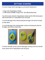
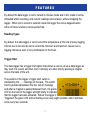
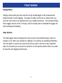
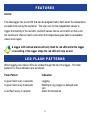
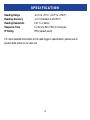
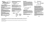
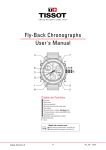
Tinytag Transit 2
Manual
2
CONTENTS
Warnings . . . . . . . . . . . . . . . . . . . . . . . . . . . . . . . . . . . . . . . . . . . . . . . . . . . . . . 4
Getting Started . . . . . . . . . . . . . . . . . . . . . . . . . . . . . . . . . . . . . . . . . . . . . . . . . 5
Features . . . . . . . . . . . . . . . . . . . . . . . . . . . . . . . . . . . . . . . . . . . . . . . . . . . . . . 6
LED Flash Patterns . . . . . . . . . . . . . . . . . . . . . . . . . . . . . . . . . . . . . . . . . . . . . . 9
Specification . . . . . . . . . . . . . . . . . . . . . . . . . . . . . . . . . . . . . . . . . . . . . . . . . . 10
Calibration . . . . . . . . . . . . .. . . . . . . . . . . . . . . . . . . . . . . . . . . . . . . . . . . . . . .11
Battery Replacement . . . . . . . . . . . . . . . . . . . . . . . . . . . . . . . . . . . . . . . . . . . 12
Approvals . . . . . . . . . . . . . . . . . . . . . . . . . . . . . . . . . . . . . . . . . . . . . . . . . . . . 13
Warranty . . . . . . . . . . . . . . . . . . . . . . . . . . . . . . . . . . . . . . . . . . . . . . . . . . . . . 14
Disposal . . . . . . . . . . . . . . . . . . . . . . . . . . . . . . . . . . . . . . . . . . . . . . . . . . . . . 14
Further Information . . . . . . . . . . . . . . . . . . . . . . . . . . . . . . . . . . . . . . . . . . . . . 15
3
WARNINGS
•
•
•
•
•
•
If this equipment is installed or used in a manner not specified by the manufacturer
then the protection provided by the equipment may be impaired.
This equipment contains a lithium battery. Danger of explosion if the battery is
incorrectly fitted. Do not cut open, incinerate, recharge or expose to temperatures in
excess of 100°C (212°F).
The battery should be replaced by a trained technician using the battery supplied in
the appropriate manufacturer’s service pack.
This equipment should only be interfaced to a UL or CSA listed computer with RS232
levels of not more than ±12V.
This equipment should only be interfaced to equipment which is powered by a Safety
Extra Low Voltage Supply. The maximum voltage levels are to be 30V rms, 42V peak
or 60Vdc and separated from hazardous voltages by double or reinforced insulation.
For the United States consider a Safety Extra Low Voltage Supply to be a Class 2
source as defined in the National Electrical Code. If the unit is connected to a
computer outdoors the computer must also comply.
This equipment should be used within the temperature range and other
environmental conditions specified in this manual.
4
GETTING STARTED
To use the Tinytag Transit 2 data logger you will need the following items:
•
•
A copy of the Tinytag Explorer software
A USB Inductive Pad OR a Tinytag Transit / Talk USB Download Cable
You will first need to install the Tinytag Explorer software and the USB inductive pad or
cable as described in the Tinytag Explorer quick start guide.
To use the data logger with an inductive pad place the logger in the centre of the pad
as shown below.
To use the data logger with a download cable, remove its lid and plug the cable into
the logger’s jack socket as shown below.
For further information on how to start the data logger recording, and to view recorded
results, please see the Tinytag Explorer quick start guide.
5
FEATURES
Memory Type
The Tinytag Transit 2 has a non-volatile memory, which means that its battery can be
replaced, once the logger has been stopped, and the data held on it will be retained.
Total Reading Capacity
The data logger can store a total of 8,000 readings. If minimum and/or maximum
values are selected (see Reading Types overleaf) then the memory is split equally
between the different reading types selected.
All of the following features are programmable and are set in the logger
using the Tinytag Explorer software. For further information on
programming a data logger, please see the Tinytag Explorer quick start
guide
Logging Interval
The frequency at which the data logger will record can be set from once every second
to once every ten days. Additionally, the logger has two logging modes; seconds
mode and minutes mode.
Continued . . .
6
FEATURES
By default the data logger is set to record in minutes mode and in this mode it can be
offloaded whilst recording, and current readings can be taken, without stopping the
logger. When set to record in seconds mode the logger has to be stopped before
either of these functions can be performed.
Reading Types
By default, the data logger is set to record the temperature at the end of every logging
interval, but it can also be set to record the minimum and maximum values over a
logging interval as well, or any combination of the three.
Trigger Start
The data logger has a trigger start option that allows a user to set up a data logger as
they wish it to record, and then start it remotely at a later time by passing a magnet
across the back of the unit.
The position of the logger’s trigger start switch is
indicated by the · · · markings on its base. The switch
itself is positioned between the two sets of markings
and when a magnet is passed between them, the green
LED on the front of the logger will light briefly to indicate
that the logger has been activated. Before the logger is
“triggered” the green LED will be flashing once every eight seconds; after it will flash
once every four seconds.
7
FEATURES
Delayed Start
Setting a delay start gives the user time to get a data logger to the measurement
location before it starts logging. Two types of delay can be set; a relative time (e.g.
one hour from now) or an absolute time (e.g. midday tomorrow). The maximum delay
that a logger can be set for is 45 days, and if no delay start is selected the logger will
start recording immediately.
Stop Options
The data logger can be configured to stop in one of three different ways; when it’s
memory is full, after a set number of readings or to continue to recording indefinitely.
The first option is useful if you want to ensure you don’t record over any important
data, the second if you only want to record for a short period and the third if you want
to leave the unit logging continuously.
8
FEATURES
Alarms
The data logger has a red LED that can be programmed to flash when the temperature
exceeds limits set by the customer. The user can set two independent values to
trigger the flashing of the red LED, and both values can be set to latch so that a unit
will continue to show an alarm even when the temperature goes back to acceptable
values once again.
A logger with latched alarms will only flash its red LED whilst the logger
is recording, if the logger stops the red LED will stop as well.
LED FLASH PATTERNS
When logging, two status LEDs are visible through the lid of the logger. The flash
patterns for these indicators are as follows:
Flash Pattern
Indication
A green flash every 4 seconds
A green flash every 8 seconds
Logging
Waiting to Log (trigger or delayed start
set)
Alarm limit breached
A red flash every 4 seconds
9
SPECIFICATION
Reading Range
Reading Accuracy
Reading Resolution
Response Time
IP Rating
-40°C to +70°C (-40°F to +158°F)
<0.4°C between 0 and 50°C
0.01°C or better
10 mins to 90% FSD in moving air
IP54 (splash proof)
For more detailed information on the data logger’s specification, please see its
product data sheet on our web site.
10
CALIBRATION
This data logger is configured during its manufacture to meet the specification quoted
in this manual.
We recommend that the calibration of this data logger should be checked annually
against a calibrated reference meter.
A UKAS traceable certificate of calibration can be supplied if the data logger is
returned to Gemini for a service calibration. For further information see:
www.tinytag.info/calibration
11
BATTERY REPLACEMENT
Battery Type
Renata CR2325
Replacement Interval
Annually*
*If logging intervals of less than five seconds are used continuously, the battery life of
the data logger will be reduced and the battery will need to be replaced more
frequently.
Before replacing the battery the data logger must be stopped.
When replacing the battery, wait at least one minute after removing the old battery
before fitting the new one.
Data stored on the logger will be retained after a battery is replaced.
If used at low temperatures the data logger should be allowed to warm to room
temperature before it is opened to avoid condensation forming inside it.
A service kit for the Tinytag Transit 2, containing a replacement battery
and servicing instructions, can be ordered from your supplier using the
part number SER-9514.
12
APPROVALS
This logger complies to BS EN 12830, between -30 and +30°C, in the following
categories:
S; T; C; D; 1
Gemini Data Loggers (UK) Ltd. operates a Business Management System which
conforms to ISO 9001 and ISO 14001.
13
WARRANTY
•
•
This product carries a manufacturing defects warranty of 12 months from the date of
purchase. Units returned under warranty will be repaired or replaced at the
manufacturer’s discretion. This warranty does not cover mishandling, modification or
battery replacement and is subject to the standard Terms and Conditions of Sale, a
copy of which is available on request.
The equipment/goods are sold “as is” and with “all faults” (applies in USA).
Claims under warranty should be referred to the point of sale.
DISPOSAL
•
•
Data loggers, accessories and batteries should be disposed of at
organised facilities, where available, in line with local regulations.
In accordance with the WEEE directive Gemini Data Loggers (UK) Ltd. will
take back and dispose of any equipment purchased directly. Equipment
not purchased directly should be returned to the point of sale for disposal.
14
FURTHER INFORMATION
Further information on Tinytag data loggers, software and accessories can be found
on our web site at:
www.tinytag.info
If you should have any further questions, please contact your distributor or:
Gemini Technical Support
t: +44 (0)1243 813009 e: [email protected]
15
Gemini Data Loggers (UK) Ltd.
Scientific House, Terminus Road,
Chichester, West Sussex,
PO19 8UJ England.
www.tinytag.info
t: +44 (0)1243 813000
e: [email protected]
16
9800-0040: Issue 8 (6th March 2015)