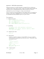
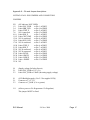
1
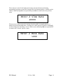
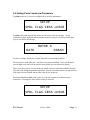
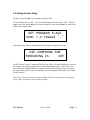
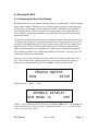
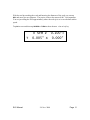
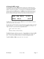
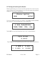
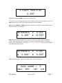
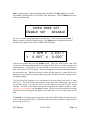
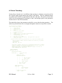
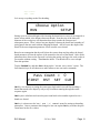
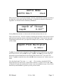
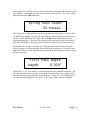
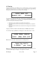
Electronic Lead Screw Users Guide
© 2008 John Dammeyer
Automation Artisans Inc.
[email protected]
http://autoartisans.com/ELS/
ELS Manual
24. Nov. 2008
Page 1
Contents:
i) Revisions
ii) Acknowledgments
iii) Conventions
1. Introduction
2. User Interface
3. Configuring the Electronic Lead Screw
3.1. Getting Started
3.2. Setting Units
3.3. Setting Z axis Lead Screw Parameters
3.4. Setting X axis Cross Slide Parameters
3.5. Setting Flags
4. Running the ELS
4.1. Configuring the run time display.
4.2. Using the MPG control.
4.3. Turning and reducing the diameter.
4.4. Screw Threading
4.5. Tapering
5. Quick Reference
6. Appendix 1 – Electrical Connections.
7. Appendix 2 – Calculating Thread Depth.
8. Appendix 3 – How Tapering works on the ELS.
9. Appendix 4 – Menu Quick Reference Guide.
10. Appendix 5 – Updating the Firmware
11. Appendix 6 – RS-232/485 Monitor information.
12. Appendix 7 – Schematics
13. Appendix 8 – Pin and Jumper Descriptions
ELS Manual
24. Nov. 2008
Page 2
i) Revisions
Date
01NOV08
Author
John Dammeyer
Revison
0.02
Description
Changed text for button from ‘ENTER’ to ‘OK’
to match overlay
09NOV08
John Dammeyer
0.03
24NOV08
John Dammeyer
0.04
Added Revisions Table and RS232 reference
section
Added Pin and Jumper Descriptions supplied by
Richard Edwards.
ELS Manual
24. Nov. 2008
Page 3
ii) Acknowledgments
ELS Manual
24. Nov. 2008
Page 4
ii) Conventions
The ELS display is made up of two lines of 20 characters and three types of
information are displayed: a Run Time display; Menu display or Parameter Entry
display.
Run Time Display:
The run time display is shown whenever the the SCREW or TURN button is
pressed.
T
0 SFM Z 0.100”=
0.005” X 0.000”
The Menu Displays always show the Menu Names on the top line in upper case
characters and a set of up to four Menu Options on the second line. Underneath
the Menu Options are are four function buttons that line up with the four Menu
Options.
Each Function key tap brings up either a new Menu Option or Parameter Entry
screen. For each Menu Option the first line displays in upper case characters an
expanded description of the acronym displayed over the Function Key.
SETUP
SPDL FLGS CRSS LDSCR
Parameter Entry:
At the end of each sequence of Menu Options is a Parameter Entry. The text
describing the parameter is in upper and lower case and the parameter is displayed
on the second line with whatever units are relevant.
\
Turn Pitch
0.0050”
ELS Manual
24. Nov. 2008
Page 5
1. Introduction
ELS Manual
24. Nov. 2008
Page 6
2. User Interface
Manual Pulse Generator
The MPG Button on the top right hand side represents a 16 position quadrature encoder
to allow movement of the carriage left or right by turning the dial. Pressing down on the
dial actuates a button that allows a user to select between several preset distance per
detent values and to choose which axis the dial moves.
Numeric Keypad
There’s a numeric keypad for entering parameters, function keys for menu driven
options and a predefined set of buttons to make the ELS more user friendly.
ELS Manual
24. Nov. 2008
Page 7
Movement Buttons
Tapping the single < or > jog buttons move the carriage a predetermined amount and if
held down, move the carriage at the threading or turning rate. The << and >> buttons
slew the carriage at full speed. With those 4 buttons it’s pretty easy to maneuver the
carriage and therefore the tool bit to an exact position. Similarly the ^,v buttons move the
cross slide in and out if an X axis motor is connected and enabled. The LCD displays the
motion in user units like inches or millimeters.
Setup Buttons
The BEGIN/END buttons set the begining and ending points for the automatic operation.
The system always moves the carriage in the direction from BEGIN to END so cutting left
or right hand threads and turning to or from the headstock is really easy. Even if you jog
past the BEGIN or END point the START Button takes you to the correct position in the
THREAD or TURN cycle which is displayed on the LCD screen.
Function Buttons
Labels above each button on LCD display determine function when ONLINE LED is off.
When ELS is READY or RUNNING the ONLINE LED is BLINKING or ON respectively
and then the function buttons serve as hot keys to access system information.
o FN1 – Z axis start and end position
o FN2 – X axis start and end position
o FN3 – Threading control
o FN4 – Taper Turning features
ELS Manual
24. Nov. 2008
Page 8
3. Configuring the Electronic Lead Screw
How to configure the ELS for your machine.
3.1 Getting Started:
Configuring the ELS for your machine. Refer to Appendix I for the electrical
connections. Much of the setup can be done before anything is connected to the ELS.
The only exception is the ESTOP input which is usually a Normally Closed (NC) switch
that opens when activated. An NC switch is used for safety because an open circuit fault
like a broken wire to the ESTOP switch will act the same as the switch activation.
Power it up –
E-LEADSCREW
Ver PIC18F4685 1.03m
If the ELS beeps and shows:
ESTOP INPUT
ACTIVE!!
then you will then have to solve a hardware problem before you can go ahead and set up
the rest of the parameters. ESTOP is a serious situation and for safety reasons the ELS
insists that the issue be solved before anything else can be done. That means it’s not
possible to temporarily override it while operating the lathe.
By default the ESTOP input is allowed to be left open circuit (not connected) and the
parameter inversion flag is set ON. If you have the ESTOP switch connected and the
button not asserted (closed switch to ground) the ELS thinks it’s in ESTOP. To go
further, assert the ESTOP by pressing and latching your ESTOP so the switch is open.
Then tap the ESC key. The message should go away. Leave it for now with ESTOP on
and we’ll set it up later when we set up the system flags.
ELS Manual
24. Nov. 2008
Page 9
Press the ESC key to enter IDLE mode until you see this screen and begin entering
parameters.
Choose Option
RUN
SETUP
3.2 Setting Units
Before you set up the various machine parameters you want to choose the units
compatible with the type of work you do. Tap RUN | UNITS | METRIC
SCREW OR TURN UNITS
Metric Mode is
OFF
Tap the '.' key to toggle the OFF to ON and tap OK to save if you want all units in
millimeters, leave it OFF to remain in imperial units. Then tap ESC twice to return to the
'Choose Option' menu and enter the SETUP menu by tapping the FN4 key.
SETUP
SPDL FLGS CRSS LDSCR
Now choose 'LDSCR | PARAM' to set up lead screw (Z Axis) parameters.
MOTOR Z
RATE
ELS Manual
PARAM
24. Nov. 2008
Page 10
3.3 Setting Z axis Leadscrew Parameters
MOTOR Z PARAMETERS
ACCL PTCH BKLSH STPS
We need to set up Acceleration, Pitch, Backlash and the number of motor steps per
revolution. The default Acceleration value of 9000 is probably adequate to start but press
the FN1 key to verify the setting. If it’s not 9000 tap the DEL key to erase it, enter the
number 9000 and press OK to accept it. The ELS beeps twice every time a new value is
saved to permanent EEROM memory. (More on acceleration later).
Motor Z Acceleration
9000_
Tap the ESC key to move up one menu and now select PTCH to set up the lead screw
pitch.
LEADSCREW PITCH
TPI PITCH
METRIC
If you know the lead screw pitch in Turns per Inch tap the FN1 button under the TPI text.
The other two options are pitch in inches or mm. Check your lathe operator’s manual for
this information. As in setting the acceleration, tap the DEL key to erase the current
setting and enter the new value and tap OK. Then tap ESC to return to the previous
memory.
ELS Manual
24. Nov. 2008
Page 11
Imperial Leadscrew
10.0
TPI
The ELS has only a single previous menu memory so tapping the ESC key again returns
us to the Option Memory. Press FN4 | FN4 to get back into Lead Screw Setup and Motor
Z parameters. Press FN3 to select BKLSH and enter in the lead screw backlash or 0 if you
don’t know what it is.
Leadscrew Backlash
Backlash
0.000”
Tap ESC to return up one menu to:
MOTOR Z PARAMETERS
ACCL PTCH BKLSH STPS
Tap FN4 (STPS) to select 'Motor Z Steps' per Lead Screw Revolution.
Motor Z Steps
01600_ Steps/Rev
The number entered for this parameter is pretty easy to determine. The stepper motor
driver usually turns a stepper motor that has a base 200 steps per revolution. If it’s a
ELS Manual
24. Nov. 2008
Page 12
micro-stepper driver this number is multiplied by a constant like 8 or 10. In the case of
the on board micro-stepper driver the number is 8 so the motor has a minimum of 1600
steps per revolution. If the motor is directly coupled to the lead screw, key in this
number and tap OK.
If you have pulleys between the motor and the lead screw then you need to multiply this
number by the pulley ratio. Say for example, the Motor has a 16 tooth pulley and the
lead screw has a 40 tooth pulley. That’s a 2.5:1 ratio so the motor moves 2.5 x 1600
which equals 4000 steps per lead screw revolution.
Tap ESC twice to return to the 'Choose Option Menu' and then tap FN4 (SETUP) again.
Next set up the Lead Screw rate by tapping FN1 (RATE).
MOTOR Z MOVE RATE
SLEW DELAY
MOVE
There are three available parameters. SLEW, DELAY & MOVE.
If the ELS has the on board micro-stepper driver installed then it can drop it to a lower
power holding mode after a certain amount of time has passed. The following menu lets
you set the number of seconds before power is reduced. External drivers may have their
own parameter for this.
Time Till Step Power
Down
000
x 1.0S
If you are using the on board micro-stepper drive you can leave it at 0 and the motor will
always remain at full power even after it's stopped. Set it to a value between 1 and 255
and the ELS will wait that number of seconds before setting the motor to 50% power.
We’ll leave the DELAY alone for now and set up the SLEW and MOVE values. Maximum
possible step rates are 20000 steps per second.
MOTOR Z MOVE RATE
SLEW DELAY
MOVE
ELS Manual
24. Nov. 2008
Page 13
The SLEW rate is used for the high speed carriage movement buttons and during
programmed operation to return the carriage back to the BEGIN position. Initially set this
value to 10000 and tap OK to accept and then press ESC to return back to the previous
menu.
Motor Z Slew Rate
10000
The Move rate is used to move the carriage when the spindle is stopped and the >, <
buttons are pressed and held down. It needs to be a slow speed so you don’t accidentally
run the carriage into something. Set it to 3000 to start with and tap OK to accept and ESC
to return to the 'Choose Option' menu.
Motor Z Move Rate
5000
ELS Manual
24. Nov. 2008
Page 14
3.4 Setting X axis Leadscrew Parameters
Tap FN4 SETUP so we can now configure the cross slide parameters.
SETUP
SPDL FLGS CRSS LDSCR
Tap FN3 (CRSS) and note that the menus are the same as for the carriage. Set up
acceleration, pitch, backlash and the number of motor steps per revolution in the same
way as you did for the carriage.
MOTOR X
RATE
PARAM
As in the Carriage, the MOTOR X MOVE RATE has a SLEW and MOVE option.
The MOVE rate is used when the ^ and v keys are pressed and held. Don’t set the MOVE
rate too high or the tool will run into the work before you can release the button.
There is no direct way to test the SLEW rate which is used to insert and withdraw the tool
from the work during programmed operation. Instead, determine a MOVE rate that will not
skip steps or loose position and use that value for the SLEW rate.
The Setup Menu has a FN1 (SPDL) entry to set up the number of encoder lines per
revolution. Currently this entry can be set but is not used.
SETUP
SPDL FLGS CRSS LDSCR
ELS Manual
24. Nov. 2008
Page 15
3.5 Setting System Flags
Finally we have the FN2 (FLGS) parameter flags section.
Use the number pad ^, v and ‘.’ Key to scroll through the menu entries. The ‘.’ Button
toggles the value and the OK key is used to accept the value and the ESC key restores the
value to the original value.
SET PROGRAM FLAGS
SCRL ^,V TOGGLE '.'
Each menu entry has text describing the flag stating the setting is ON or OFF.
USE COMPOUND FOR
THREADING IS
OFF
The ELS doesn’t need a Compound Slide (or Top Slide as it’s also called) since it moves
the X and Z axis along the hypotenuse of the thread angle triangle. If the X axis isn’t
powered then this flag should be ON so that on each pass the carriage returns to exactly
the same BEGIN position since the manually operated compound slide takes care of both
Z and X motion.
This Flag is also set to ON when using threading mode to do multiple pass turning and
facing. More on that later under ELS operation.
ELS Manual
24. Nov. 2008
Page 16
Tap the scroll down v key to bring up the next flag.
BROACH MODE MOVEMENT
IS
OFF
The spindle must be turning in order to cut threads or turn the work so before and during
automatic motion the ELS checks to make sure the spindle is turning. When using the
lathe as a shaper to broach or cut splines the spindle is locked in position and should not
turn. Setting 'Broach Mode Movement' disables the test for spindle turning. This
option is also useful for testing ELS movement when it's not even connected to a lathe.
AUTOMATIC X
MOVEMENT IS
OFF
If there is a stepper motor connected to the cross slide, set this flag ON, otherwise set it
With it OFF, the ELS will prompt you to enter and remove the tool from the work
between threading or turning passes. Remember, the ‘.’ Key toggles the value, the OK
key accepts and stores it and the ESC key discards it. We’ll cover the manual nonautomatic menus later.
OFF.
The next flag is TAPER TURNING which is only useful if you have a powered cross slide.
For now you should set off.
TAPER TURNING
TAPERING IS
OFF
If you have wired up the Electronic Half Nut set this flag ON. Otherwise set it OFF.
Initially while learning how to use the ELS it may be beneficial to leave it turned off so
there is one less thing to think about.
ELS Manual
24. Nov. 2008
Page 17
ELECTRONIC
HALFNUT IS
OFF
Tap on the scroll down v key to show the ESTOP INVERSION menu.
INVERT ESTOP LINE
INVERTED IS
ON
Changing this flag will result in an immediate error message. At this point, to clear the
error, the ESTOP input pin must be changed to the opposite of what it was. If the ESTOP
flag was on it means the ELS can run without an ESTOP switch connected. If the ESTOP
flag is OFF, then the ESTOP input pin must be connected to ground. This is the preferred
method of using the ESTOP. A normally closed (NC) switch connects the ESTOP line to
ground and pressing the ESTOP opens this contact. Then if there is an open circuit fault,
like if a wire to the switch breaks, an ESTOP also occurs.
If you accidentally change the flag to OFF without an ESTOP button connected to ground
the ELS will enter the ERROR state and it won’t be possible to change the flag back to ON.
There are two solutions:
•
Connect a wire to the DB-25 ESTOP pin and connect it to GND and then
change the flag. That will cause the ERROR message. Disconnect the
wire and continue setting up the ELS.
•
Turn off the ELS, hold down the DEL key and power up the ELS again.
WARNING! This will set all parameters back to factory settings. Use this as a
last resort.
Now setup the Invert Limit Switch Flag.
ELS Manual
24. Nov. 2008
Page 18
INVERT LIMIT SWITCH
INVERTED IS
OFF
The limit switch is only tested during programmed movement. During Jogging the
switch input is not tested. With the flag ON, the switch needs to connect the input to
ground to create a limit condition. With the FLAG OFF, the switch needs to be normally
closed to ground and will open when a limit is encountered. Using the MPG knob results
in a programmed distance movement and could also generate a LIMIT Error.
USE ONBOARD STEPPER
STEP MOTOR IS
OFF
Set the 'Use Onboard Stepper Motor' Flag on if you have and are using the on board
micro-stepper.
The Z axis DIR and STEP pins on the DB-25 connector should not be connected to
anything as they now have a totally different purpose and are used internally for the
micro-stepper.
Z AXIS DIRECTION
INVERTED IS
OFF
The carriage must move in the correct direction in order for the automatic operations to
work correctly. If the carriage moves to the right when the < button is pressed then the
flag must be set to the opposite value.
The cross slide must move inwards toward the work when the ^ button is pressed. If it
doesn’t then set the flag to the opposite value.
ELS Manual
24. Nov. 2008
Page 19
X AXIS DIRECTION
INVERTED IS
OFF
The STEP pin on the DB-25 connector goes high to approximately 5V for 5uS when a
step is required. Some external drivers need the step line to go low for a step pulse.
Consult your driver specifications to determine if this Flag needs to be set.
Z AXIS STEP POL
INVERTED IS
OFF
As in the 'Z AXIS STEP' polarity, consult the driver specifications to determine what is
needed.
X AXIS STEP POL
INVERTED IS
OFF
The 'Serial Port' is currently used for diagnostics so this flag is used to enable an echo
of what is typed. If controlled by a remote computer the echo is usually not wanted.
SERIAL PORT
ECHO CHARS IS
OFF
Basic machine setup is now complete.
ELS Manual
24. Nov. 2008
Page 20
4. Running the ELS:
4.1 Configuring the Run Time Display.
Running the ELS isn’t a lot different than working with a manual lathe. Whether turning
down a shaft, turning a shoulder or screw cutting, the basic principles remain the same.
The ELS does all cutting at an X axis position of 0.000” or 0.00mm; also called the X
Axis HOME position. This is exactly the same as turning the cross slide handle for a
0.010” depth of cut and then setting the cross slide dial to zero just before the turning
operation is started.
The ELS measures the cross slide motion as a change in radius. Movements are always
considered to be a depth of cut or distance moved into or away from the work. There is
no explicit assumption that the ELS knows where the tip of the tool is in relation to the
lathe centre axis. That's because a manual lathe operator will often readjust the tool
holder or tool bit angle to get an optimum cut. After each tool bit position change the
lathe operator would have to recalibrate the absolute tool position. Necessary in a CNC
system but awkward in a manual lathe.
There is a way to set the absolute X position of the tool bit relative to the lathe center
line. This is needed if the spindle speed needs to be displayed in Surface speed per
Minute (SFM or SMM) instead of RPM. Tap the ESC key to go into IDLE mode.
Choose Option
RUN
SETUP
Then select RUN | UNITS | SFM
SPINDLE DISPLAY
SFM Mode is
OFF
Tap the '.' key to change the FLAG from OFF to ON and tap OK to save. Tap the ESC key
twice to return to the 'Choose Option' menu and select RUN | X | LOC to show the
'Tool Tip Position' menu.
ELS Manual
24. Nov. 2008
Page 21
With the tool tip touching the work and knowing the diameter of the work you can tap
DEL and enter in a new diameter. The precise value to the nearest 0.001” isn't important.
You are just telling the ELS approximately where the tool tip is so it can calculate surface
speed.
Tap OK to save and then tap SCREW or TURN to show the Run Time Display.
T
ELS Manual
0 SFM Z 0.100”=
0.005” X 0.000”
24. Nov. 2008
Page 22
4.2 Using the MPG control.
The Manual Pulse Generator (MPG) produces 16 pulses per revolution and can be
electronically connected to either the Z or X axis and move the axis a predetermined
amount. The active axis symbol [=,<,>] beside the Z or X Digital Read Out (DRO)
indicates which axis the MPG controls. The MPG has detents which make it easy to
generate single movements and also has a button that is activated when the button is
pressed, resulting in the display of the MPG Menu and the next detent increment.
NEW JOG DSTZ
CNCL SELX
0.005”
ACPT
Tap FN1 (CNCL) to reject the new value or FN4 (ACPT) to use the displayed value and
return back to the 'RUN Time Display'.
For each click or detent the ELS moves the selected axis, Z in this example, one of four
predefined distances. To select a new distance press the MPG downward again. The
'NEW JOG DISTZ' increments to the next predefined value:
[0.001”, 0.005”, 0.010”, 0.020”]
or
[0.02mm, 0.02mm, 0.05mm, 0.10mm]
The FN2 label displays which axis is not active. Tapping FN2 (SELX) changes the MPG
axis to the cross slide, changes the label to SELZ and the display text to 'NEW JOG
DSTX'. The active axis indicator character is set beside the appropriate DRO.
Tap ACPT, SCREW or TURN to return to the 'Run Time Menu'.
ELS Manual
24. Nov. 2008
Page 23
4.2 Turning and reducing the diameter.
With the spindle turning you can use the cross slide jog buttons (^,v) to move the tool in
and out and then use the carriage jog button (<, >) to move the carriage at the predefined
turning rate. Needs editing or embellishment.
Choose Option
RUN
SETUP
Let’s set up a turning rate of 0.005” per revolution. Tap the ESC key and then the FN1 (Z
RUN Parameters). Next select FN1 (TURN) to set the turning pitch.
Z RUN PARAMETERS
TURN THRD POS JOG
Tap the DEL key to clear the field and then enter in 0.005” and tap the OK key.
Turn Pitch
0.0050”
Tap the TURN key in the Setup Buttons group and the run time display menu shows up.
T
ELS Manual
0 RPM Z 0.100”=
0.005” X 0.000”
24. Nov. 2008
Page 24
Let’s look at the information displayed. The ‘0’ beside the text RPM tells us the spindle
isn’t turning. If the spindle is turning and the yellow light appears to be blinking but the
value remains at zero it means that the ELS is having trouble with the spindle signal.
There could be troubles with the sensor or some other hardware problem.
The letter ‘T’ at the left side of the screen tells us the number beside the ‘T’ represents
pitch with the double quote representing inches. If the pitch were in mm then the number
might be 0.12m where the ‘m’ represents millimeters. The ‘T’ for pitch means the lathe is
will use the TURN parameters rather than the ‘S’ SCREW THREADING parameters.
On the right hand side of the display the ELS shows the position of the Z axis (carriage)
and the X axis (cross slide). The ‘=’ on the same line as the Z tells a user that the MPG
knob will move the carriage. If the ‘=’ is on the second line then the MPG will move the
cross slide X axis.
Whenever the RUN time information is displayed the GREEN Status light blinks stating
that the ELS is ‘READY’. When the ELS is in ‘READY’ mode the ‘Action’ and ‘Movement’
buttons can cause the motors to turn and the lathe hardware to move.
Now that the basic lathe parameters have been set it’s a good time to familiarize yourself
with the operation of the Movement buttons.
Tap the left move button <. The carriage should move 0.001” (or 0.02mm) to the left
and the display should show -0.001”. It may be hard to see that short a movement so tap
it 9 more times without holding it down and the 0.010” distance should be obvious.
Next tap the > button once. If you’ve got a fairly large backlash value set the lead screw
motor will rapidly take up the backlash before moving the lead screw the single 0.001”.
Notice even with the backlash movement the Z axis display only changes 0.001”.
Now try the slow move operation. Press and hold one of the two movement buttons < or
>. The carriage will now move at the predefined move rate. If it’s too fast, go back to
'SETUP | LDSCR | RATE | MOVE' and set the MOVE rate to a smaller number. Turn on
the spindle and note that the RPM display stabilizes after 10 seconds showing an average
speed. Press and hold one of the two Movement buttons again and note that now the
carriage moves very slowly; in fact the carriage moves at the TURN rate of 0.005” per
spindle revolution.
Before you try and cut metal, try the SLEW buttons: <<, >>. These move the carriage very
quickly and are useful for getting the carriage close to where you want to start cutting.
There is no delay like the MOVE buttons.
ELS Manual
24. Nov. 2008
Page 25
Finally if you’ve got a motor on the cross slide you can try the ^, v Movement buttons to
make the cross slide go in and out. If there isn’t an X axis motor installed then operation
of the cross slide and compound (top slide) are done manually.
So chuck up a piece of steel or aluminium extending out a few inches. Using the slew
buttons bring the tool bit up until it’s in line with the end of the bar. Tap the Zero Z
button to set a new Z Home position and clear the Z Position display to 0.000”.
Next move the tool towards the bar using the ^ button. When it’s close, turn on the
spindle and move the tool bit in until it just scratches the bar. Tap the Zero X button to
establish the X Home position.
With the spindle turning, press and hold the < move button and watch as the carriage
moves left at 0.005” per revolution. Continue holding the < button until the Z readout
shows -0.500”.
Automatic Operations:
With the carriage at -0.500” tap the END Setup button. This menu shows up and you
have the opportunity to edit it by tapping the DEL key and entering a new value (don’t
forget the ‘-‘ sign if the carriage is closer to the chuck and on the left side of 0.000”).
Z End Position
-0.500”
Tap OK to save the value and tap the TURN button to go back to READY mode and
withdraw the tool bit, using the v key, far enough so it clears the bar.
Now let’s move the carriage back to where we started. We can use the ALT-ZHOME
function for this. Press and hold down the ALT button and while holding it down tap the
Zero Z button. The carriage moves automatically back to the 0.000” location.
Use the > button to move the carriage to the 0.100” location. This will be our BEGIN
position for automatic turning. A BEGIN position in front of the work is needed to allow
the stepper motor to accelerate up to turning or threading speed. Once at that location tap
the BEGIN Setup button and just like the END Setup position a menu comes up to let you
adjust, accept or reject (ESC) the value.
ELS Manual
24. Nov. 2008
Page 26
Z Start Position
0.100”
Tap OK and then tap TURN to return to the READY State.
Let’s check and see what parameters are set. Whenever the run time display is active, the
FNx buttons provide short cuts to other parameters and information.
shows the BEGIN and END positions for automatic carriage movement along with the
current location of the carriage.
FN1
SETPOINTS
B 0.100”
Z 0.595”
E -0.500”
shows the BEGIN and RETRACTED positions of the cross slide. BEGIN should be
0.000” and RETRACTED will be positive for external turning and negative for boring. It
needs to be set at a point so the tool bit will always clear the work between the carriage Z
axis BEGIN and END positions.
FN2
SETPOINTS
B 0.000”
FN3
X
R
0.000”
0.100”
is a quick jump to a special threading menu. More on that later.
PASS COUNT = 0
CNCL RST
SET CLR
ELS Manual
24. Nov. 2008
Page 27
is a quick jump to a special tapering menu and allows the FN1, FN4 keys to enable
and disable Tapering and FN3 to set up the taper parameters. Tap the TURN button to get
back to the READY state.
FN4
TAPER MODE OFF
ENABLE SET
DISABLE
So you’ve verified that the parameters are all correct. You’ve done a pass with the <
button to remove a little bit from the work. The TURN button was pressed to put the
machine in the READY state with the GREEN LED blinking.
T
0 RPM Z 0.100”=
0.005” X 0.000”
Turn on the spindle and press the START button. The cross slide retracts, and if the
carriage isn’t at the BEGIN position the first thing the ELS does is send the carriage to the
BEGIN position. It then moves the tool from the X Retracted Position and sends it
back to the HOME or 0.000” position. Next the carriage moves towards the END position at
the TURN pitch rate. When the carriage reaches the END position, it stops and the ELS
retracts the cross slide back to the RETRACTED position and then sends the carriage back to
the BEGIN position.
The last part of the sequence is the movement of the cross slide back to the 'X Home
Position'. The ELS finishes there because if you want to do another pass, you use the
jog inwards button ^ to move the tool in for the depth of cut desired, 0.010” in this
example. Just look at the display and tap the button until the depth is reached. Then,
and this is very important, tap the Zero X button. We have just re-zeroed the cross slide
dial and the next turning pass will again cut at 0.000” but it’s 0.010” deeper than the last
time.
Tap START to do another pass! Remember, each time the ELS makes an automatic pass
it cuts at the X equal to 0.000” or 0.00mm position and returns with the carriage at the 'X
Retracted Position'.
ELS Manual
24. Nov. 2008
Page 28
4.3 Screw Threading.
Cutting Screw threads isn’t a lot different from turning to a diameter except the tool bit
has a special shape which matches the profile of the thread. Tools for standard threads
are pointed while ACME or trapazoidal tool bits have flat ends. The pitch is coarser than
what's used for turning and the operation is done with multiple passes with parameters
similar to the G-Code G76 instruction.
The chart below shows the parameters needed for a screw thread cutting operation. The
menu tree pictorial shows how to navigate through the menus to set up what’s needed.
G76 Simulation has arguments:
Global Variable array indices
X
-- X End position.
Z
-- Z End position
Q
-- Spring Pass Count
P
-- Pitch
H
-- First Pass cutting depth
I
-- In feed thread angle.
R
-- X Begin
K
-- Z Begin position with room for synchronization
L
-- Thread chamfer... not used in ELS.
C
-- X retracted position
B
-- Last Pass cutting depth
T
-- Taper angle. Not used directly. ELS System uses " per foot.
J
-- Cutting pass depth
Variables used for calculating new position of X,Z after each threading pass.
When the system is READY (Green LED Flashes) and the FNC3 key is pressed
the menu shows:
PASS COUNT = nn
FIRST RST
SET CLR
After RST is pressed a recalculation is performed and Pass Count is updated.
This way an operator can start and stop the threading but has to explicitly
change to a new set of the threading operations.
When the SET softkey is pressed the display is changed to activate the
THREAD PARAMETERS Menu shown below.
THREAD PARAMETERS
TURN THRD POS JOG
|
PITCH ANGLE PASS SPRING
FLOAT FLOAT
|
Spring Pass Count
|
uint8 n
|
THREAD Pass Param
DEPTH FRST EACH LAST
|
|
|
|
|
|
|
Last Path Depth
|
|
|
FLOAT 0.dddd
|
|
|
|
|
Each Pass Depth
|
|
FLOAT 0.dddd
|
|
|
First Pass Depth
|
FLOAT 0.dddd
|
DEPTH CALCULATION
DEPTH MULT
CALC
|
|
|
|
|
Calculated Depth
|
|
FLOAT
d.dddd
|
|
| Depth Ptch Multiplier
| FLOAT
d.dddd
ELS Manual
24. Nov. 2008
Page 29
Depth of Thread
FLOAT
d.dddd
Let's set up everything needed for threading.
Choose Option
RUN
SETUP
Setting up to cut a thread begins with choosing the thread size in TPI or in an imperial or
metric PITCH which is the distance between threads. Next the size of the lathe and
diameter of the work piece will determine how deep to make the first pass and
subsequent passes. There’s also a last pass depth to clean up the thread and a number of
spring passes that are made without changing the depth. And of course the depth of the
thread is the most important parameter for an accurate screw thread.
Based on an assumption that the tool bit has the correct shape and tip radius, the thread
depth parameter is from the surface of the material to the root of the thread. After all the
parameters have been set the first task is to bring the cutting tool up to the work so that it
just touches without cutting. Then Zero the X axis. The thread will be cut to a depth
from this position.
Tap the THREAD key and then FN3 to bring up the 'Thread Pass Count' screen. The
four function keys are all shortcuts to other menus or are one touch commands.
Pass Count = 0
FIRST RST SET CLR
Key is a shortcut to setting the FIRST pass depth which is useful for tweaking a
thread that needs to be deeper by only a tiny bit without running through the entire
sequence again.
FN1
key RST calculates and resets the pass count back to the number required to cut a
brand new thread.
FN2
key is a shortcut to the 'ESC | RUN | Z | THREAD' menu for setting up threading
parameters. Once a parameter has changed a user can tap the FN2 key to RESET the pass
count based on the new values.
FN3
ELS Manual
24. Nov. 2008
Page 30
clears the pass count effectively stopping further threading passes until the pass
count is reset.
FN4
Example Threading Operation:
The example assumes that you’ve just completed a turning sequence and that the last
turning pass has left a smooth finish on the work and the X axis home position is at 0.00.
The thread will be 20 TPI (0.050” pitch) and 1/2” long where the Z Axis Home position
is the face of the work and the thread is RH towards the headstock.
Install the thread tool bit in the tool holder and insure that the tool bit is properly adjusted
with a thread gauge. Now it’s time to re-adjust the X axis so that the threading tool bit is
just touching the surface. Turn on the spindle and using the jog buttons adjust the tool bit
so it just starts to scratch the surface. Then tap the ZERO X Button so that the X BEGIN
position is set at 0.00.
Next, stop the spindle, withdraw the tool bit with the ‘v’ jog button so it no longer
touches the work and move the carriage until the tip of the tool is at the edge of the face
or start of the thread. This is the Z axis Home position so tap the ZERO Z Button. The Z
BEGIN position is still to the right of the face at 0.100”. The ELS needs a short distance
to bring the lead screw up to speed before the tool bit starts cutting. Otherwise the first
part of the thread will be the wrong pitch.
The Z END position is still at 0.500” so we are set to cut a ½” long thread. You may want
to turn a groove at 0.500” to the thread depth to serve as a runout area or just let the lead
screw decelerate and consider the last half turn or so of the thread non-functional.
Now let’s set up the rest of the thread parameters. Once done, most of the time you may
never change many of these. Tap FN3, THREAD MODE to show the Pass Count Display
and then FN3 to short cut through to the THREAD Parameters menu.
THREAD PARAMETERS
PTCH DPTH ANGL PASS
Tap FN1 PITCH, then TPI and finally enter 20. Tap OK to accept and then ESC twice to
reach the 'Choose Option' menu. Tap 'RUN | Z | THRD | DEPTH' to set up thread
depth.
ELS Manual
24. Nov. 2008
Page 31
DEPTH MENU
DEPTH MULT
CALC
There are two ways to set the thread depth. The first, and traditional method is to look up
the depth for a given pitch and enter that depth, or calculate it using the information in
Appendix 2 as derived from the Machinery Handbook.
Depth of Thread
Depth
0.027”
Just tap FN1 DEPTH and DEL to clear out the old value and enter the new one.
There is an easier way. The ELS contains a thread depth calculator which uses the thread
pitch and a MULTIPLIER constant to determine the final depth. If you use the same type
of threading tool bit then once you adjust this multiplier for your lathe, cutting threads
will be simple.
Depth Ptch Multipler
0.5413”
Tap ESC if you don't want to change the value or DEL to clear it and then use the number
keys to tap in a new value and OK to accept. Tap ESC, then FN4 CALC to have the ELS
determine the thread depth based on the thread pitch which is 0.027” for our 20 TPI
thread. Tap OK to accept the new value and ESC twice to return to the 'Choose Option'
menu.
Now the thread angle. Tap 'RUN | Z | ANGL'. We’re cutting a standard ANSI 60
degree thread so we enter in the ½ angle minus a little bit. A value of 29.5 is fine. DEL
to clear the old value, the number keys to enter a new one and OK to accept; listen for the
double beep and then ESC to go back up to the previous menu.
ELS Manual
24. Nov. 2008
Page 32
Tap FN4 (PASS) to select the passes menu.
THREAD PASS PARAM
FRST EACH LAST SPRNG
Select FN2 (FRST).
First Pass Depth
Depth
0.010”
Key in a value that you feel your lathe can comfortably cut without too much tearing or
excessive load. A value between 0.005” (0.12mm) and 0.010” (0.25mm) is usually
adequate. Leave enough depth so there is room to make at least one EACH pass and a
LAST pass. Tap OK to accept and then ESC to go up one level and then tap FN2 (EACH) to
enter the EACH pass menu.
Each Pass Depth
Depth
0.003”
After the first pass the ELS continues with additional passes each time removing the
amount specified in the 'Each Pass Depth'. Set this depth to an amount that suits the
material and the ability of your lathe.
Finally you have the chance to add a last finishing pass that only skims the surface of
your new thread.
Last Pass Depth
Depth
0.001”
ELS Manual
24. Nov. 2008
Page 33
Most lathes have some flex and even after that last pass it's possible that the thread is still
not complete. Tap the ESC key after you've finished setting the the 'Last Pass Depth'
parameter and select FN4 SPRNG pass.
Spring Pass Count
03 Passes
The 'Spring Pass Count' parameter sets up the number of passes after the last pass where
the depth is not changed. Once the ELS has finished cutting the thread it stops and you
can try a nut on the thread. If it's tight, Tap the START button, and the ELS runs an
additional spring pass. Take note if any more metal is removed from the thread groove.
Run additional single cycle spring passes until no more metal is taken from the groove.
At this point, the nut may or may not fit. It depends on the radius of the tool bit and
whether it properly reflects the depth chosen with the MULT parameter. If the nut is still
tight the ELS has one other feature that lets you make an additional pass without redoing
the entire sequence.
First Pass Depth
Depth
0.029”
Change the 'First Pass Depth' to a value deeper than the original thread depth. The
ELS determines that the first path is deeper than the total depth so runs a single cutting
pass and then a the programmed set of spring passes. Test the nut. If it still doesn't fit,
run a few more spring passes or set a new 'First Pass Depth' and do it all again.
ELS Manual
24. Nov. 2008
Page 34
4.4 Tapering
Tapering with the ELS can be difficult and very confusing unless you take an systematic
approach to setting parameters. The fastest way to set up tapering is to tap the FN4 key
during Ready Mode (when the Green Ready LED is flashing).
TAPER MODE OFF
ENABLE SET
DISABLE
The display Shows the status of the Taper Mode as ON or OFF although the active axis
symbol [=,<,>] beside the 'Run Time Menu' Z or X Digital Read Out (DRO) also lets
you know at first glance that tapering is enabled.
'=' Tapering OFF so the tool bit moves parallel to the spindle axis
'<' Tapering ON and the tool bit moves inwards as the carriage moves towards the
headstock
'>' Tapering ON and the tool bit moves outwards as the carriage moves towards the
headstock.
Tapering is enabled or disabled with the FN1 (ENABLE) and FN4 (DISABLE) buttons.
To set the taper angle, tap FN2 (SET) to bring up the 'TAPER MENU CHOICE' menu.
TAPER MENU CHOICE
DIST ANGL DIR LIST
FN1 (DIST) lets
you set the 'Tapering Ratio' in inches per foot.
Tapering Ratio
0.00000 “ per Foot
FN2 (ANGL) lets you set the taper as an angle measured relative to the spindle axis. The
maximum possible angle is 45 degrees. See Appendix 3 for details.
ELS Manual
24. Nov. 2008
Page 35
Taper movement to
headstock is OUT >
To toggle between the two possible taper modes, tap the '.' key. The phrase ' OUT >'
changes to 'IN
<' and back each time the '.' key is tapped. Tap OK to accept and ESC
to cancel.
Tapping FN4 (LIST) brings up a convenience menu of 'PREDEFINED TAPERS'.
PREDEFINED TAPERS
MRSE JACB ASRT CSTM
MRSE
JACB
ASRT
CSTM
MORSE TAPER LIST
JACOB TAPER LIST
ASSORTED TAPER LIST
CUSTOMIZED TAPERS
#0 thru 7
#0, 1, 2, 2A, 3, 4, 5, 6, 33
R8, ER, 5C, 3C, IT
User1 to User4
Tap FN1 to FN4 to select the catagory and then use the ^,v keys to scroll through the
selections, Tap OK to select and save or ESC to return to previous menu. The numerical
value of the taper is available for inspection or modification by choosing the Angle
Selection described earlier.
Once you've chosen the taper you need to decide which direction the taper should go.
Keep in mind that you want to keep the cross slide lead screw preloaded against the work
so that as the ELS cuts the taper it doesn't have to remove the backlash after each
movement of the Z axis.
An outside taper should be smaller further away from the spindle '>'. Cutting a taper in
this manner means the X axis is always moving inwards as the carriage moves to the
right.
An inside taper is exactly the opposite. As the carriage moves to the right, the cross slide
lead screw needs to be constantly pulling into the work away from the lathe center line
therefore the taper is larger further away from the spindle '<'.
ELS Manual
24. Nov. 2008
Page 36
Next think about retracting the cutting tool out of the work while returning to the BEGIN
position. Outside tapers need an 'Cross Slide Retracted' that clears the work completely.
The retracted value is relative to the cutting position 0.00 at the start of the cut, not the
end.
Insert sketches here for showing tool path.
ELS Manual
24. Nov. 2008
Page 37
Appendix 1 -- Electrical Connections.
ELS Manual
24. Nov. 2008
Page 38
Appendix 2 -- Cutting threads with the ELS.
Cutting threads on a lathe like any potentially intimidating project can be broken down
into a number of smaller steps. To illustrate the procedure let’s assume we want to create
a 1” long 5/16-18 TPI thread on the end of a 3/8” diameter shaft.
In our example the shaft is oversize so the first step is to reduce it to the major diameter
of the thread. The machinery handbook states that the Major Diameter for a UNC
5/16”thread is 0.3125” and the Minor Diameter is 0.2452”. We need to install a turning
tool and set up to reduce the work to the Major Diameter.
If our tool bit was a perfectly sharp V then the depth of our thread would be (MajorD –
MinorD)/2 which is 0.0337”.
The Height H of a sharp thread is listed as:
H = 0.86603 x Pitch of thread. = 0.86603 * 0.0556 = 0.0481”
This height extends above the Major Diameter by 0.125 * H = 0.006” and provides an
initial clue as to how far in we’ll move the tool bit into the work; in this case a maximum
of 0.0421”. The root or bottom of the thread would also be a sharp V if we could grind a
tool bit that way but in reality there will be a small flat or optional rounded tip with a
width of
0.25 x Pitch = 0.25 * (1/18 TPI) = 0.0139”
That also results in a thread depth reduction of
0.25 x H = 0.25 x 0.0481 = 0.0120
The total depth of tool travel is now 0.0421” – 0.012 = 0.0301.
The short way to this value is
(Thread Pitch x 0.86603) x 0.625 = Thread Pitch * 0.5413
(1/18 TPI) x 0.5413 = 0.0301” which is our depth of cut for an 18 TPI thread.
This is a starting point and is totally dependant on the profile of your tool bit. If you use
a carbide bit with predictable tips you might find you will need to adjust the constant
slightly since the radius of the tip puts the point at a different location and a tip with no
radius.
Enter 0.5413 into the 'Depth Pitch Multiplier' menu under 'RUN | Z | THRD |
DPTH | MULT'
ELS Manual
24. Nov. 2008
Page 39
Appendix 3 – How Tapering works on the ELS.
The ELS carriage motion is dependant on the speed of the spindle and the cross slide is
dependant on the position of the carriage. This is different from a CNC system that runs
the tool bit along the hypotenuse of the triangle created together by the carriage and the
cross slide as a co-ordinated movement.
On the ELS, the cross slide is slaved to the carriage which means the maximum distance
the X axis (cross slide) can move is one motor step per Z axis (carriage) motor step.
Regardless of the reduction ratios or lead screw pitch, the maximum 1:1 step remains
constant.
If the pitch and ratio of the cross slide and carriage are identical then for each carriage
and cross slide motor step the tool bit will follow a 45 degree angle. However, usually
the cross slide screw is a finer pitch than the carriage so the potential angle is also less
since the cross slide will move a shorter distance per step than the carriage.
This means the maximum taper angle is normally less than 45 degrees. Not really a
problem since most mechanical taper attachments do far less than 45 degrees and the
compound is used for acute angles greater than the taper capability. To turn these types
of angle automatically use a CNC system.
As in a manual lathe, it's best to always turn a taper in a direction so the cross slide lead
screw is loaded against the cut. Going in the other direction will result in an uneven taper
determined by the cross slide backlash.
Ensure that the X retraction value is far enough away from the largest diameter of the
work. It's easy to accidentally set the retraction value to a setting inside the cutting
surface.
ELS Manual
24. Nov. 2008
Page 40
Appendix 4 – Menu Quick Reference Guide.
To be determined
ELS Manual
24. Nov. 2008
Page 41
Appendix 5 – Updating the Firmware
WinPIC settings.ini file:
[PicMain]
Left=212
Top=15
Width=500
Height=366
CodeMemBgColor=0
CodeMemFgColor=65280
DataMemBgColor=16777215
DataMemFgColor=0
SpeedButtonsVisible=1
ToolWinVisible=0
ToolWinLeft=30
ToolWinTop=30
Language=en
LanguageTestMode=0
[MostRecentFiles]
file0=C:\PROJECTS\ELeadscrew\PIC18Code\SRC\Output\ELS.hex
file1=C:\PROJECTS\ELeadscrew\PIC18Code\src\Output\ELS.hex
file2=
file3=
file4=
file5=
[INTERFACE]
InterfaceType=10
SupportFile=ELSProgrammer.ini
ExtraRdDelay_us=10
ExtraClkDelay_us=5
SlowClockPulses=0
IdleSupplyVoltage=1
PortAccessDriver=0
[COM84_INTERFACE]
ComPortNumber=1
UnusualIoAddress=0
[LPT_INTERFACE]
LptPortNumber=1
UnusualIoAddress=0
[SESSION]
HexFileName=C:\PROJECTS\ELeadscrew\PIC18Code\src\Output\ELS.hex
[PROGRAMMER]
ProgramWhat=7
UseBulkErase=1
Disconnect=0
VerifyDifferentVoltages=0
DontCareForOsccal=0
DontCareForBGCalib=0
ClearBufferBeforeLoading=1
NeedVddBeforeRaisingMCLR=1
VerboseMessages=0
[PIC]
PathToDevFiles=C:\Program Files\Microchip\MPLAB IDE\Device
DeviceType=PIC18F4685
HasFlashMemory=0
UnknownCodeSize=4096
UnknownDataSize=256
ELS Manual
24. Nov. 2008
Page 42
WinPIC ELSProgrammer.ini file:
[Info]
Purpose=PIC programmer interface definition for WinPic and "ELS"
[ProgrammerControlLines]
VppOnOff=!D3
PullMclrDown=!D4
DataOut=D0
OutEnable=nc
DataIn=ack
ClockOut=D1
DataOutWhileReading=1
ClkEnable=nc
VddOnOff=nc
Connect=nc
RedLed=nc
GreenLed=nc
OkButton=nc
Insert PDF of Programmer adaptor and text on how to run WINPIC plus WPINPIC_ELS
config file.
ELS Manual
24. Nov. 2008
Page 43
Appendix 6 – RS232/485 communications
Diagnostic information is available through the on board RS232 port configured for
115kbaud, 8 bits, no parity and one stop bit. Using a PC terminal emulator program like
Hyperterm (for PC’s running Windows before VISTA) the ELS has a series of
commands that can be used to diagnose or display status information.
They are currently only useful for diagnostics when updating software. Eventually, the
serial port will be used as a MODBUS port for external control of a VFD or MODIO.
For commands that modify EEROM or ports, use at your own risk.
The commands are:
‘E’ – EEROM information
EMn,b -- Modify memory location.
EPn -- Put EEROM location to display
EFn -- Fill EEROM with n
EDx -- Dump EEROM page x to screen
ER -- Report EEROM in format of C nnncfg.h file.
‘F’ – system Flags
ThreadFLAGS: RDY=xx, RUN=xx RUNFLAG=xx, STOPFlags=xx,
SystemCmd=xx
EEROM FLAGS: SYS=xx, MGMT=xx, ZMOTOR=xx, XMOTOR=xx, COMM=xx
Local Flags: Move: RUN=xx,
‘In’ – display I/O port values.
PORT n=xx
‘M’ – display Menus
Each Menu in the ELS is displayed with the MENU #, the type of variable it
references and if it’s dependant on any other menu values. The Min/Max values
are currently not used.
LCD:07
-------------------| Imperial Leadscrew |
|Pitch
|
-------------------FLOAT:
0.250
Min= 0.001, Max= 200.000
Dependant on: 2E
‘Oxx’ – Output to port B.
PORT B =xx
ELS Manual
24. Nov. 2008
Page 44
‘t’ – spindle Tracking variable.
SpinRate nn
‘s’ – Status flags
CONTROLFlags=xx
SYS: d, MV: d
ZStepFlg: xx
XStepFlg: xx
ActiveFlg: xx
‘v’, ‘?’ – print Version
E-LEADSCREW
Ver PIC18F4685 1.10d
Here's the schematic of the ELS to DE-9S connector.
ELS Manual
24. Nov. 2008
Page 45
Appendix 7 – Schematics
Insert PDF copies of Schematics
ELS Manual
24. Nov. 2008
Page 46
Appendix 8 – Pin and Jumper descriptions.
LISTING OF ALL ELS JUMPERS AND CONNECTORS
JUMPERS
JP1
1-2
3-4
5-6
7-8
9-10
11-12
13-14
15-16
17-18
19-20
21-22
23-24
25-26
27-28
29-30
31-32
33-34
35-36
(NU indicates NOT USED)
Links ENC_PWR
to Pin 1 of DB25
Links ERR_LED
to Pin 14 of DB25
Links STEP_X
to Pin 2 of DB25
NU 8 connected
to Pin 15 of DB25
Links DIR_X
to Pin 3 of DB25
Links CHG_PMP
to Pin 16 of DB25
NU 14 connected
to Pin 4 of DB25
Links RUN_LED
to Pin 17 of DB25
NU 18 connected
to Pin 5 of DB25
Links STEP_Z
to Pin 6 of DB25
Links DIR_Z
to Pin 7 of DB25
NU 24 connected
to Pin 8 of DB25
NU 26 connected
to Pin 9 of DB25
Links ESTOP
to Pin 10 of DB25
Links LIMITS
to Pin 11 of DB25
Links -INDEX
to Pin 12 of DB25
Links +INDEX
to Pin 13 of DB25
NU
J4
2-1
2-3
(Supply voltage for Index Sensor)
Links ENC_PWR to VCC (5v)
Links ENC_PWR to VRAW (Incoming supply voltage)
J9
2-1
2-3
(LCD Backlight supply (Use 2-3 for supplied LCD))
Connects to V_CC (5v
Connects to V_RAW (12v or greater)
J11
(Allows power to Pic Programmer 12v Regulator)
This jumper MUST be fitted
ELS Manual
24. Nov. 2008
Page 47
CONNECTORS
J1
1
2
(Stepper supply. Max 55v)
DRV_PWR
GND
J2
1
2
(Possible Voltage source for a different LCD Display)
LCD_DRIVE
GND
J3
1
2
(Board Power AC or DC Nom 12v but 15 to 20v for PIC programming)
BRD_PWR_A
BRD_PWR_B
J5
1
2
3
4
(Onboard Stepper Drive connections)
PHASE_A2
PHASE_A1
PHASE_B2
PHASE_B1
J6
1
2
3
4
5
6
7
8
9
10
11
12
13
14
15
16
17
18
19
(DB25 connector)
ENC_PWR
STEP_X
DIR_X
NC
NC
STEP_Z
DIR_Z
NC
NC
ESTOP
LIMITS
-INDEX
+INDEX
ERR_LED
NC
CHG_PMP
RUN_LED
GND
GND
ELS Manual
24. Nov. 2008
Page 48
J6
20
21
22
23
24
25
(DB25 connector - continued)
GND
GND
GND
GND (Use for Estop circuit)
GND (Use for Limits circuit)
GND (Use for Encoder (Index) power)
J7
1
2
3
4
5
6
(PIC Programming Interface)
DB25M pin on the Programming PC Parallel port
GND
Any one of 19-25
P_/RESET
6 (D4)
P_/VPP_ON
5 (D3)
P_ISPC
3 (D2)
P_ISPD_IN
2 (D1)
P_ISPD_OUT
10 (ack)
J8
1
2
3
4
5
(For Development use))
ISPC
ISPD
GND
VCC
Vpp
J10
(Allows the connection of an external Keypad)
See circyuit diagram for connections
CONN1
RS232/485 Header
1
Gnd
2
RX232
3
TX232
CONN5
CAN Header
1
CAN_LO
2
CAN_HI
3
GND
4
TRM2
5
TRM1
ELS Manual
24. Nov. 2008
Page 49
VR4
1
2
3
(Half nut connection)
GND
HALF_NUT
VCC
TEST POINTS (Situated in the Stepper Drive area (not silk screened)
TP1
TP2
Test point for checking VR1 (setting of drive current)
TP3
Test point for checking VR2 (setting of drive current)
GND Ground connection for above test
ELS Manual
24. Nov. 2008
Page 50