1
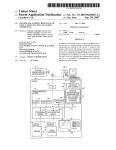
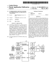
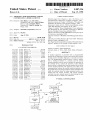
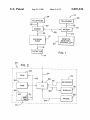
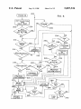
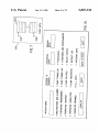
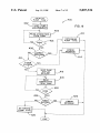
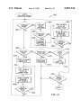
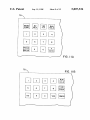
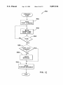
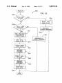
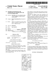
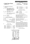
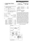
US005807336A
United States Patent
[191
Russo et a1.
[451
[541
APPARATUS FOR MONITORING AND/OR
CONTROLLING A MEDICAL DEVICE
[751
Inventors; Sam Russo, Lisle; Sho Chen,
North?eld, both of I11_; Larry Wilson,
POWay, Calif; Joseph P_ Maser,
Wheaten, 11L; A1311 E_ Jordan, San
Diego, Calif
5,807,336
Patent Number:
Date of Patent:
[111
Sep. 15, 1998
OTHER PUBLICATIONS
Assignee: Sabratek Corporation, Niles, Ill.
Selected pages from Chapters 1 and 2 by Foley, et al.,
“Fundamentals of Interactive Computer Graphics”, 1982.
Selective portions of Chapter 9 of MayheW, “Principles and
Guidelines In Software User Interface Design”, 1992.
Electronic’s Article of Feb., 1990 by Jack Shandle, entitled
“Who Will Dominate the Desktop in the ’90s?”.
Chapter 5 entitled “Direct Manipulation” from Schneider
man Designing the User Interface: Strategies for Effective
App1_ No; 691,872
Abbott Laboratories’ LIFECARE® Blue Line System prod
Human—Computer Interaction, published 1992.
_
uct literature, copyrighted 1990.
Flled:
Aug‘ 2’ 1996
Literature of BaXter’s MultiPleX Fluid Management System.
Int. Cl.6 .................................................. .. A61M 31/00
1988
US. Cl. ......................... .. 604/131; 604/207; 604/246
Field Of Search ................................ .. 604/31, 50, 65,
Literature describing Baxter’s F10—Gard 6201 Volumetric
Infuslon PumP> copynghted199z- _
604/66, 67, 93, 131, 207, 246
One—Page Art1cle by Jerry H1rsch ent1tled “Portable IV frees
patients”, printed in The Orange County Register. 1991.
References Cited
.
US. PATENT DOCUMENTS
_
Primary Examiner—MaX Hmdenburg
4,413,314 11/1983 Slater et a1. .......................... .. 364/188
4,561,443
4,676,776
4,696,671
.
(List cont1nued on neXt page.)
12/1985 Hogrefe et a1.
Attorney) Agent) Or Firm_FitCh, Even, Tabin & Flannery
. 604/65 X
6/1987 Howson .................................. .. 604/31
9/1987 Epstein et a1. .......................... .. 604/67
[57]
4,731,051
3/1988
A medical
4,828,545
4,901,221
5/1989 Epstein et a1.
604/66
2/1990 KOdOSky 618.1. ..................... .. 364/200
medical device disposed at a ?rst room location and a remote
monitor and/Or Controller disposed at a Second room loca
5/1990 OT_k1n etf11~ -
tion. The programmable medical device is used to admin
4,925,444
lg;
,
,
P15011611 . . . . . . . . .
. . . . .. 604/67
123413’??? ft a1‘ """"""""""
ou ree
a.
is
provided
-
364/550
......
apparatus
With
a
programmable
ister a medical treatment to a patient, and the remote
..
5,155,693 10/1992 Altmayer et a1. .
01116 et a1.
ABSTRACT
-
-
mhomtogforit?’n‘gir may be ulse? to mom?“ th; 05mm? of
5,207,642
5/1993
572307623
7/1993 Guthrie et a1_
. . . .. 604/68
433/72
dev1ce, and/or to transfer data from the med1cal dev1ce to the
5,291,190
5,295,062
3/1994 scarola et a1_
3/1994 Fukushima
340/8256
364/188
remote mon1tor/controller. The apparatus may alloW vo1ce
communication betWeen the remote monitor/controller and
5,338,157
8/1994
Blomquist . . . . .
1/1996 Blomqulst
5,558,638
9/1996 Evers et a1.
5,573,506
5,643,212
11/1996
Vasko
the patient Who is receiving treatment via the medical device
. . . . ..
'
604/65
7/1997 Coutré et a1. ......................... .. 604/131
19 Claims, 12 Drawing Sheets
IO
/ 34
'f
TELEPHONE
36“
30
A28 22
~ MODEM I
‘
\38
12
PUMP
V
‘
Mam,
/ CONTROLLER
2O
WIS
26
TELEPHONE I
MODEM
CATHETER
t 6,“ lea
While the medical device is being monitored and/or con
trolled from the remote location. The remote monitor/
controller may also include means for determining the type
of medical device to Which it is connected
604/66
. ... ... ... ..
t e Operanon, O
604/31
364/146
345/119
364/578
3/1995 Wllson ct a1~
5/1995 Takahar‘? et a1‘ '
5’485’408
evlce> Comm
. . . . . . .. 417/2
5,376,070 12/1994 Puivis et al- -
5300246
5’412’4OO
t 6 ,me lea
5,807,336
Page 2
OTHER PUBLICATIONS
Article by Bedder, et al. entitled “Cost Analysis of TWo
Implantable Narcotic Delivery Systems”, published Mar. 14,
“Block Medical: GroWing With Home Infusion Therapy,”
taken from INVIVO, The Business and Medicine Report,
Apr., 1991; pp. 7—9.
1991.
“IEEE—488 and VXIbus Control, Data Acquisition, and
Pp. 66—71 from book chapter entitled “MiniMed Technolo
Analysis . . . the Most Choices,” select pages taken from
gies Programmable Implantable Infusion System”, describ
National Instruments, Application SoftWare Products and
ing clinical trials from Nov., 1986.
A. H. McMorris, J. L. KelleWay, B. Tapadia and E. L.
Dohmann, “Are Process Control Rooms Obsolete?”, taken
from Control Engineering, pp. 42—47, Jul., 1971.
Abbott Laboratories, The Blue Line System, Lifecare, copy
Application SoftWare OvervieW, (1991), 17 pages.
“LabVIEW®2 User Manual; Chapter 2, The Front Panel,”
taken from National Instrument’s Corporation, Jan., 1990;
right 1990.
L. C. Sheppard, “Computer Based Clinical Systems: Auto
mation and Integration,” taken from 39th ACEMB, Sep.
13—16, 1986, pp. 73—75.
J. C. Crone, Jaromir Belic and Roger W. Jelliffe, M.D., “A
Programmable Infusion Pump Controller,” taken from 30th
pp. 1—36.
Annual Conference on Engineering in Medicine and Biol
ogy, Nov. 5—9, 1977; pp. A—35826 through A—35837.
U.S. Patent
Sep- 15,1998
Sheet 1 0f 12
/
5’807’336
IO
34
f
fze
TELEPHONE
TELEPHONE
J
22
MODEM
~
\
~
MODEM
‘
/_
A24
l2
INFUSION
‘
"/
REMOTE
PUMP
/-
MONITOR /
CONTROLLER
20
“I6
7
CATHETER
FIG. I
I4
20
\ FIG. 2
l_
_
_
_
_
:
_
_
_
_
_
_
_
_
_
_
_
_
_
_
_
/-s2
_|
24
I
I
ROM
74
'
~68
66
f
l1 e4\
76
(
|
I
II
KEYBOARD
L
I
RAM
I
l/O
)
\
I
MP
I
I
1_
I
80
|
/_70
82|
XMIT
REC _
_
i/78|
_
_
MOUSE
84/
_
_
_
_
_
_
_
__
__
_
_
_
_
_
__
/ l
I
_
_l
U.S. Patent
Sep. 15,1998
( POWER 0N )
Sheet 3 0f 12
200)
FIG. 5
IN I TIALIZATION
AND
SELF TEST
/
202
5,807,336
RESUME
YES
?
204
2C6
‘r
234
2|2
230
NO
“£46613?
25
?
PER'gOOs
NO
DO
0
YES
236
PROGRAM
PCA
-
LOCKOUT
2'4
N0
YES
SEQUENCE
PROZGSRAM
\
PERIODS
2|6
NO
226
232
‘
iNTER
2|8
NO
222
CONTINUOUS
N0
AUTQ
7
MITTENT
?
228
YES
RA?MP
Z24
YES
'
\
PROGRAM
YES
INTERMITTENT
PROGRAM
AUTO-RAMP
PROGRAM
CONTINUOUS \220
2l0\
268
‘%
READY
‘
STOP
TO RUN
INFUSION
260\ +
NO
$63’?
HOLD
a?‘ ;
REPORT
ALARMS
KEY
262
NO
YES
TURN
OFF
‘
YES
270
U.S. Patent
Sep. 15,1998
Sheet 4 0f 12
(REOORO)
302
F|G.6
‘\
PROGRAMMING
COMPLETE
5,807,336
3O4\_
YES
sTORE
PROGRAMMEO
PARAMETERS
‘
‘P
STORE RUN
PARAMETERS
STORE TOTAL
VOLUME INFUSED
STORE
TOTAL
VOLUME INFUSED,
NEW RATE, VOLUME
STORE
TOTAL
~
VOLUME INFUSED,
ALARM TYPE
INFUSION
PL
COM
326
ETE
STORE TOTAL
~
MALFUNCTION
?
vOLuME
_,
INF-‘USED
STORE TOTAL
YES
VOLUME
INFUSED,
MALFUNCTION
_"
TYPE
sTORE REsuMEO
T“
PARAMETERS
LOCKOUT
PROGRAMMING
COMPLETE
YES
SLQE'EDMS’FTES
TE
?
~
336/
340
BOLUS
REQUEST
YES
STORE
- GIVEN/NOT GIVEN.
BOLUS AMOUNT
_
U.S. Patent
Sep. 15, 1998
Sheet 6 0f 12
5,807,336
/
( STORE DATA I
382
7
SET POINTER TO
NExT ADDRESS
384
IS
POINTER AT
LAST ADDRESS
386
?
SET POINTER TO
FIRST ADDRESS
‘
388
WRITE TIME
STAMP IN LOG
‘
WRITE EVENT
DATA IN LOG
END
FIG.8
\d/39O
380
U.S. Patent
Sep. 15,1998
Sheet 7 0f 12
< IDENTIFY )
PUMP TYPE
402
5,807,336
/400
,
SEND PUMP
9
ID REQUEST
404
READ CHARACTERS
4
FROM PUMP
E
DETERMINE
PUMP TYPE
ERROR
MESSAGE
CORRECT
RESRPONSE
S'ENgPPUMP
I
LAY
4l6
REQUEST
“J
READ
CHARACTERS
K
FROM PUMP
/
424
ERROR
MESSAGE
V
DETERMINE
PUMP TYPE
END
H
_
U.S. Patent
Sep. 15,1998
Sheet 8 0f 12
USER
( SELECTS
MODE )
5,807,336
f 450
454
COMMAND
YES
460
‘
MO'PDE
452
GET
PUMP'S
DISPLAY
FROM PUMP
'N
‘
O
‘
456
A
COMMAND
lNPUT
ON scmzsw
458\TRANSMIT
COMMAND
TO PUMP
465
MONITOR
MODE
DOWNLOAD
?
'?
DATA LOG
466
YES
DISPLAY PUMP
MONITOR
DOWN LOA D
DATA LOG
VIEW
DATA LOG
467
476
GET PU MP'S
DISPLAY
FROM PUMP
478
NO
SHOW PUMP'S
DISPLAY
ON SCREEN
468)
YES
469
FIG. IO
U.S. Patent
Sep. 15,1998
Sheet 9 0f 12
5,807,336
FIG. IIA
78
\
FIG. llB
U.S. Patent
Sep. 15,1998
Sheet 10 0f 12
/458
COMMAND
PUMP
480
SEND
.-/
PUMP COMMAND
482
READ
CHARACTERS
FROM PUMP
PUMP ECHO
CORRECT
7
488
ERROR
MESSAGE
SEND
ACKNOWLEDGEMENT
FIG. I2
END
5,807,336
U.S. Patent
Sep. 15,1998
Sheet 11 0f 12
/5OO
502
DATA DUMP
5,807,336
FIG. I3
YES
ACTIVE
504
?
,
RESET DATA
DUMP FLAG
508
DATA DUMP
COMMAND
TRANSMIT
7
ERROR MESSAGE
512
j
SET TRANSMIT
POINTER TO
OLDEST DATA
/
’
RESPOND TO
OTHER c0 MMAN D
SET DATA
DUMP FLAG
506/
'_\
FETCH FIRST
DATA BYTE
-\
UPDATE
TRANSMIT
POINTER
/
F0 RM AT DATA
IN ASCII
520
T
ENABLE
TRANSMIT
INTERRUPT
“\
522
SEND FIRST
DATA BYTE
524 j
T
END
5'0
U.S. Patent
Sep. 15,1998
Sheet 12 0f 12
5,807,336
/55O
552
DATA DUMP
ACTIVE
N0
?
RESPOND TO
OTHER
556
INTERRUPT
ALL DATA
SENT
7
YES
N0
562
554)
FETCH NEXT M
DATA BYTE
558
J
DISABLE
r
TRANSMIT
UPDATE
TRANSMIT
INTERRUPT
POINTER
564
RESET DATA
DUMP FLAG
FORMAT DATA
IN ASCII
'\
560
566
SEND
DATA BYTE
568/
\
END
FIG. l4
5,807,336
1
2
APPARATUS FOR MONITORING AND/OR
CONTROLLING A MEDICAL DEVICE
remote monitor via the communication link, and means for
alloWing voice communication betWeen the medical device
BACKGROUND OF THE INVENTION
and the remote monitor via the communication link While
the data is being transferred from the medical device to the
The present invention is directed to an apparatus for
monitoring and/or controlling a medical device, such as an
remote monitor.
In a third aspect, the invention is directed to an apparatus
having remote means for communicating With one of a
infusion pump, from a remote location.
plurality of medical devices each of Which is designed to
An infusion pump is used to automatically administer
administer a medical treatment to a patient, the one medical
liquid medicant to a patient. The liquid medicant is supplied
device being disposed at a ?rst room location and the remote
means being disposed at a second room location remote
10
from a source of medicant and pumped into the patient via
a catheter or other injection device. The manner in Which the
from the ?rst room location. The remote means includes
liquid is infused is controlled by the infusion pump, Which
means for automatically determining the type of the one
programmable medical device and means for receiving data
relating to the medical treatment of the patient after the type
of the one programmable medical device has been deter
mined. The apparatus also includes data communication
may have various modes of infusion, such as a continuous
mode in Which the liquid medicant is continuously infused
15
at a constant rate, or a ramp mode in Which the rate of
infusion gradually increases, then remains constant, and then
gradually decreases.
means coupled to the remote means for transferring data
betWeen the remote means and the one programmable
Typically, the monitoring of an infusion pump is per
formed by revieWing a visual display means incorporated in
medical device.
The one programmable medical device may have a visual
the infusion pump, and the control of the infusion pump is
display device and the means for automatically determining
performed by activating an input device, such as a keypad,
incorporated With the infusion pump. Consequently, the
monitoring and/or control of an infusion pump is performed
at the same location at Which the infusion pump is disposed.
the type of the one programmable medical device may
include means for transmitting a display request to the one
programmable medical device to request that the one pro
25
SUMMARY OF THE INVENTION
The invention is generally directed to a medical apparatus
having a programmable medical device disposed at a ?rst
room location and a remote monitor and/or controller dis
posed at a second room location.
In one aspect, the invention is directed to a medical
apparatus having a medical device for administering a
medical treatment to a patient, the medical device being
35
disposed at a ?rst room location and including means for
grammable medical device transmit display data including a
plurality of characters shoWn on the visual display device of
the one programmable medical device, means for receiving
the display data, and means for determining the type of the
one programmable medical device based upon the display
data.
The display data may include a number of characters and
the determining means may include means for determining
the type of the one programmable medical device based
upon the number of characters in the display data. The
means for automatically determining the type of the one
administering the medical treatment to the patient and
memory means for storing data regarding the medical treat
ment administered to the patient. The medical apparatus also
includes a remote monitor for monitoring the medical treat
ment administered to the patient, the remote monitor being
programmable medical device may also include means of a
disposed at a second room location remote from the ?rst
These and other features and advantages of the present
invention Will be apparent to those of ordinary skill in the art
?rst type for automatically determining the type of the one
programmable medical device and means of a second type
for automatically determining the type of the one program
mable medical device.
room location, and means for transferring the data from the
medical device to the remote monitor While the medical
device is administering the medical treatment to the patient.
45
The data may be transmitted to the remote monitor in
segmented, noncontinuous data portions, and the means for
transferring the data to the remote monitor may include
means for repeatedly transmitting portions of the data from
BRIEF DESCRIPTION OF THE DRAWINGS
FIG. 1 is a block diagram of an apparatus for adminis
tering medical treatment to a patient and monitoring the
condition of the patient;
FIG. 2 is a block diagram of the electronic components of
the remote monitor/controller shoWn schematically in FIG.
the medical device to the remote monitor and means for
generating an interrupt When one of the data portions has
been transmitted to the remote monitor, the interrupt causing
the transmitting means to transmit another of the data
portions from the medical device to the remote monitor.
1;
In a second aspect, the invention is directed to a medical 55
apparatus having a medical device for administering a
medical treatment to a patient, the medical device being
administering the medical treatment to the patient and
memory means for storing data regarding the medical treat
ment administered to the patient. The medical device also
includes a remote monitor for monitoring the medical treat
ment administered to the patient, the remote monitor being
disposed at a second room location remote from the ?rst
room location, a communication link operatively coupled
FIG. 3 is a front vieW of one embodiment of the infusion
pump shoWn schematically in FIG. 1;
FIG. 4 is a block diagram of the electronic components of
the infusion pump of FIG. 3;
FIG. 5 is a ?oWchart of the overall operation of the
infusion pump;
FIG. 6 illustrates a number of data-recording steps per
formed during the operation of the infusion pump;
FIG. 7 is a representation of a portion of the memory of
the infusion pump;
disposed at a ?rst room location and including means for
betWeen the medical device and the remote monitor, means
for transferring the data from the medical device to the
in vieW of the detailed description of the preferred
embodiment, Which is made With reference to the draWings,
a brief description of Which is provided beloW.
65
FIG. 8 is a ?oWchart of a store data routine Which can be
used to store data relating to the operation of the infusion
pump and data relating to the condition of a patient;
5,807,336
4
3
interface 102a, a nonvolatile RAM 104, a real-time clock
FIG. 9 is a ?owchart of a routine Which may be used to
identify the type of infusion pump to Which the remote
106 and the display 92, all of Which are interconnected by
monitor/controller is coupled;
a communications bus 108. The display 92 has a backlight
FIG. 10 is a ?owchart of a mode select routine of the
110 Which is selectively activated by an enable signal
remote monitor/controller;
FIGS. 11A—11B illustrate portions of visual displays
generated on a line 112 interconnecting the controller 100
and the backlight 110. Both the RAM 104 and the real-time
clock 106 are connected to a battery 114 Which supplies
poWer to them only in the absence of system poWer. The
generated by the remote monitor/controller;
FIG. 12 is a ?oWchart of a command pump routine that is
performed by the remote monitor/controller;
10
FIG. 13 is a ?oWchart of a receive routine that is per
controller 100 has a transmit buffer 116 and a receive buffer
118 connected to the communications bus 108.
The controller 100 controls the medicant infusion rate by
periodically transmitting a control signal to an ampli?er
formed by the infusion pump;
FIG. 14 is a ?oWchart of a transmit routine that is
circuit 120 via a line 122 to drive a pump motor 124 Which
drives a pumping mechanism 126, such as a rotary pump
performed by the infusion pump; and
FIG. 15 is an illustration of a graphical user menu that 15 Wheel (not shoWn) adapted to make contact With a portion of
the liquid conduit 16 (FIG. 1) connected to the catheter 14.
The controller 100 receives periodic inputs from a shaft
may be displayed by the remote monitor/controller.
DETAILED DESCRIPTION OF A PREFERRED
EMBODIMENT
FIG. 1 illustrates one embodiment of an apparatus 10 for
encoder (SE) sensor 130, Which is disposed on the shaft of
the motor 124. The SE sensor 130 may be a tWo-phase
20
motion sensing encoder Which provides tWo signal outputs
treatment means in the form of an infusion pump 12, Which
to the controller 100. The rotational speed of the motor 124
and its direction of rotation are determined by the controller
100 based upon the rate and phase relationship betWeen the
is connected to a liquid medicant injection device in the form
tWo signal outputs.
administering medical treatment to a patient. Referring to
FIG. 1, the apparatus 10 includes a programmable medical
of a catheter 14 via a liquid conduit schematically shoWn as 25
The SE encoder 130 periodically transmits the signals to
16.
the controller 100 via a line 132. Each time the signals are
The apparatus 10 includes a remote monitor/controller 20
transmitted, an interrupt is generated, and the controller 100
Which is disposed at a room location remote from the room
location at Which the infusion pump 12 is located. The
remote monitor/controller 20 could be disposed in a different
room of the same building in Which the pump 12 is disposed,
or in a different building than the one in Which the pump 12
compares the actual position of the motor shaft With its
30
desired position, and transmits a neW control signal, such as
a pulse-Width modulated signal, to the ampli?er 120 via the
line 122 to ensure that the actual speed of the motor 124
corresponds to the motor speed required for the desired
medicant infusion rate. The interrupts caused by the SE
is disposed. The remote monitor/controller 20 is connected
to a conventional voice/data modem 22 via a data link 24, 35 sensor 130 are assigned to the highest priority so that they
and the modem 22 is also connected to a telephone 26 via a
are responded to immediately, before any other actions are
voice link 28. The infusion pump 12 is connected to a
taken by the controller 100.
conventional voice/data modem 30 via a data link 32, and
The pump 12 has a number of other features not described
the modem 30 is connected to a telephone 34 via a voice link
herein, Which are disclosed in the folloWing patent
36. The tWo modems 22, 30 are interconnected to bidirec 40 applications, each of Which is incorporated herein by refer
tional voice and data communication via a communication
ence: U.S. Ser. No. 08/399,184, ?led Mar. 6, 1995, entitled
link 38, Which could be a telephone line, for eXample.
FIG. 2 is a block diagram of the electronics of the remote
monitor/controller 20 shoWn schematically in FIG. 1. Refer
ring to FIG. 2, the remote monitor/controller 20 includes a
45
microprocessor (MP) 60, a read-only memory (ROM) 62, a
random-access memory (RAM) 64, and an input/output
entitled “Cassette For An Infusion Pump; U.S. Ser. No.
(I/O) circuit 66, all of Which are interconnected by an
address/data bus 68. The microprocessor 60 has a transmit
buffer (XMIT) 70 for transmitting data bytes and a receive
08/399,183, ?led Mar. 6, 1995, entitled “Infusion Pump
With Dual-Latching Mechanism”; U.S. Ser. No. 08/398,887,
?led Mar. 6, 1995, entitled “Infusion Pump With Historical
Data Recording.”
buffer (REC) 72 for receiving data bytes. The remote
monitor/controller 20 has a keyboard 74 connected to the
I/O circuit 66 via a line 76, a display device 78, such as a
CRT, connected to the I/O circuit 66 via a line 80, and an
input device, such as an electronic mouse 82, connected to
the I/O circuit 66 via a line 84. The remote monitor/
55
controller 20 can also include one or more disk drives, such
as a hard disk drive or a ?oppy disk drive.
FIG. 3 is a front vieW of one embodiment of the infusion
pump 12 shoWn schematically in FIG. 1. Referring to FIG.
3, the pump 12 has an input device in the form of a keypad
60
90 via Which a user may input data and commands and a
display 92 for displaying teXtual messages to the user.
Ablock diagram of the electronics of the infusion pump
12 is shoWn in FIG. 4. Referring to FIG. 4, the pump 12
includes a controller 100, an electrically programmable
read-only memory (EPROM) 102 having a built-in I/O
“Infusion Pump Having PoWer Saving Modes”; U.S. Ser.
No. 08/398,977, ?led Mar. 6, 1995, entitled “Infusion Pump
With Selective Backlight”; U.S. Ser. No. 08/398,980, ?led
Mar. 6, 1995, entitled “Infusion Pump With Different Oper
ating Modes”; U.S. Ser. No. 08/398,886, ?led Mar. 6, 1995,
65
The operation of the infusion pump 12 is controlled by a
computer program stored in the EPROM 104 and executed
by the controller 100. A ?oWchart 200 of the overall opera
tion is illustrated in FIG. 5. Referring to FIG. 5, When the
pump 12 is turned on, at step 202 the pump is initialiZed and
a test of the pump operation is performed. The pump 12 may
be turned off temporarily during an infusion, in Which case
the pump 12 may continue the infusion When it is turned
back on, as described beloW. At step 204, if there is any
remaining volume of liquid to be infused by the pump or any
additional time remaining for an infusion, Which Would be
the case Where the pump Was temporarily turned off during
an infusion, the program branches to step 206, Where the
user is asked, via a message displayed on the display 92,
Whether the previous infusion should be resumed. If the user
ansWers yes (via the keypad 90), the program branches to a
5,807,336
5
6
ready-to-run step 210. If the previous infusion is not to be
resumed, the program branches to step 212.
the pump on, programs the desired infusion mode at one of
steps 220, 224, 228, 232, 236, and then turns the pump off.
The programmed infusion parameters Will be retained in the
The infusion pump 12 has a lockout mode in Which the
memory 104. The medical assistant Would then turn the
pump back on, press the “No” key in response to the
user may be prevented from programming the infusion
parameters, such as the volume to be infused or the rate of
“Programmable?” prompt at step 214, enter the lockout
information at step 216, and then turn the pump off again.
When the patient subsequently turned on the pump to
infusion. For example, the pump 12 could be programmed
by a medical assistant to deliver a particular infusion having
a particular ?oW pro?le, ?oW rate and volume to be infused.
After programming that infusion, the medical assistant could
place the pump in lockout mode, Which Would prevent the
patient from changing any of the infusion parameters. At
step 212, if the pump 12 has been previously placed in
lockout mode, the program branches directly to the ready
10
If the lockout mode Was not utiliZed, the medical assistant
or the patient could turn the pump on, program the desired
to-run step 210, bypassing all programming steps.
At step 212, if the pump is not in lockout mode, the
program branches to step 214, at Which point the program
prompts the user, via the display 92, to input Whether the
patient should be alloWed to program the pump during the
subsequent infusion. If the pump is not to be programmable,
perform the infusion, the program Would proceed from step
212 directly to the ready-to-run step 210, Which Would
prevent the patient from altering the infusion parameters.
15
infusion mode, and then press the “Run” key to start the
infusion Without ever turning the pump off.
During programming and operation, the infusion pump 12
automatically records in the non-volatile memory 104 all
signi?cant infusion data to generate a complete historical
data record Which can be later retrieved from the memory
the program branches to step 216 Where a lockout sequence
104 and used for various purposes, including clinical pur
poses to aid in determining hoW effective a particular
is performed by requesting the user to input Which infusion
modes should be locked out. If the pump is to be program
infusion therapy Was and treatment purposes to con?rm that
mable by the patient, the program bypasses step 216.
the prescribed infusion Was actually delivered.
FIG. 6 illustrates various steps at Which infusion data is
recorded that are performed during the overall pump opera
tion shoWn generally in FIG. 5. The infusion data recorded
The infusion pump 12 has ?ve basic modes of infusion: 1)
a continuous mode in Which the pump delivers a single
25
volume at a single rate; 2) an auto-ramp mode in Which the
pump delivers liquid at a rate that gradually increases to a
in the memory 104 is set forth in Table 1 beloW. A number
of events Which trigger the storage of data are listed in the
left-hand column of Table 1, and the infusion data that is
recorded upon the occurrence of each event is listed in the
right-hand column of Table 1. The time at Which the infusion
threshold rate, stays constant at the threshold rate, and then
gradually decreases; 3) an intermittent mode in Which the
pump delivers discrete liquid volumes spaced over relatively
long periods of time, such as a liquid volume every three
hours; 4) a custom mode in Which the pump can be pro
grammed to deliver a unique infusion rate during each of 25
data is recorded, Which is determined by the real-time clock
106, is also stored along With the infusion data.
different time periods; and 5) a pain-controlled analgesic
(PCA) mode during Which the pump Will periodically infuse
boluses of analgesic in response to periodic requests by the
TABLE 1
patient.
EVENT
At step 218, the pump 12 generates on the display 92 the
DATA RECORDED
Power On
Date and Time
prompt “Continuous?” to the user. If the user desires to use
Program
Infusion parameters. See Table 2.
the pump in its continuous mode, the user ansWers “yes” via
Run
Hold
Restart
Infusion parameters. See Table 2.
Total Volume Infused
Time of Restart
Rate Changes
Alarms
Infusion Complete
Malfunctions
Total
Total
Total
Total
Resume
Maintenance Date
Patient ID
Serial No.
Infusion parameters. See Table 2.
Date
Patient ID Number
Serial Number
the keypad 90, and the program branches to step 220 at
Which the continuous mode is programmed by the user by
entering a number of infusion parameters, such as the
desired infusion rate, the volume to be infused, etc. At step
218, if the user does not Want to use the continuous mode,
the user ansWers “No,” and the program branches to step
222. Steps 222—236 are generally the same as steps 218 and
220, eXcept that the user may be prompted for different
infusion parameters, depending on Which of the ?ve possible
infusion modes is selected.
After the completion of one of the steps 220, 224, 228,
232, or 236, the program branches to the ready-to-run step
210. When the user presses the “Run” key, the pump 12
enters the run mode 260 and infuses the patient With a liquid
medicant in accordance With the infusion mode selected at
one of steps 218, 222, 226, 230, 234 and the infusion
parameters entered at one of steps 220, 224, 228, 232, 236.
45
Language Change
New Language
Lockout
Pressure Select
Modes Locked Out
Bolus Request
New Pressure Setting
Given/Not Given, Bolus Amount
Titration
PoWer Off
Version No.
NeW Parameters
Time of PoWer Off
Software Version Number
Referring to Table 1 and FIG. 6, When the poWer to the
infusion pump 12 is turned on, the date and time of the
poWer turn-on is recorded. When the pump is completely
programmed pursuant to one of steps 220, 224, 228, 232,
236 (FIG. 5) as determined at step 302, the programmed
rence of an alarm condition, an alarm is reported at step 264.
At step 262, if the hold key is pressed, the infusion is stopped
at step 266, and the pump 12 Waits for the run key to be
pressed at step 268 or the on/off sWitch to be turned off at
is to be utiliZed in lockout mode, a medical assistant turns
Infused, Rate, Volume
Infused, Alarm Type
Infused
Infused, Malfunction Type
55
The pump 12 remains in the run mode 260 until the “Hold”
key is pressed, as determined at step 262. Upon the occur
step 270.
Summarizing the operation described above, if the pump
Volume
Volume
Volume
Volume
65
infusion parameters are stored at step 304, along With the
time of such storage. The particular parameters that are
stored depend upon Which infusion mode Was programmed.
Several eXamples of infusion parameters that are stored for
each of a number of infusion modes are illustrated in Table
2 set forth beloW.
5,807,336
8
7
pointer 376 is at the last memory location in which data may
be stored, the routine branches to step 386 where the pointer
is set to the address of the ?rst memory location in which
data may be stored. As a consequence of steps 384, 386, the
contents of the memory locations 372 are periodically
overwritten with new data; however, the number of memory
locations 372 is suf?ciently large so that several months of
TABLE 2
INFUSION MODE
INFUSION PARAMETERS
Continuous
Infusion Mode
Infusion Rate
Volume To Be Infused
Delay Time
data, for example, is stored before being overwritten. At
Total Bag Volume
steps 388 and 390 the data is stored in the memory location
KVO Rate
Auto-Ramp
Infusion Mode
Infusion Rate
Volume To Be Infused
10
stamp generated from the real-time clock 106 and event data
specifying the particular infusion event).
Delay Time
Total Bag Volume
Duration of Up-Ramp
Duration of Down-Ramp
15
KVO Rate
Intermittent
Infusion Mode
Total Infusion Time
Number of Doses
Dose Time
Dose Volume
patient.
When the pump enters the run mode 260 (FIG. 5) as
determined at step 306, the time at which the run mode was
infusion is performed, are stored at step 308.
25
At step 310, if the hold key is pressed, then the time at
which the hold key was pressed along with the total volume
infused at the time the hold key was pressed are stored at
step 312. The pump also stores any infusion rate changes,
such as changes caused by switching from a continuous rate
to a keep-vein-open (KVO) rate, or in the intermittent mode,
changing from a KVO rate to a higher infusion rate, the
presence of which are detected at step 314. The new rate and
35
infused at the time of the alarm are recorded at step 320. If
more characters identifying the software version of the
pump. At step 404, the remote monitor/controller 20 reads
the characters sent from the pump 12 until all characters are
received as determined at step 406 or until a predetermined
the infusion is completed as determined at step 322, the
program branches to step 324 where the time at which the
infusion was completed is stored along with the total volume
infused. At step 326, if there is a malfunction, the malfunc
tion type, the time at which the malfunction occurred, and
time period, eg ?ve seconds, elapses. The time period may
be determined by a timer (not shown). The remote monitor/
controller 20 may determine that all characters have been
received by, for example, identifying one or more termina
tion characters, such as a carriage-return character <CR>
followed by a line-feed character <LF>.
the total volume infused at the time of the malfunction are
recorded at step 328.
At step 330, if the infusion is resumed (when the pump is
The remote monitor/controller 20 is designed to interface
with different types of infusion pumps. In order to determine
which type of infusion pump the remote monitor/controller
20 is operatively coupled, a pump identi?cation routine 400
performed after the communication link between the remote
monitor/controller 20 and the infusion pump 12 is estab
lished. Referring to FIG. 9, at step 402 the remote monitor/
controller 20 transmits a pump identi?cation (ID) request to
the infusion pump 12 via the communication link 38. In
response to the pump ID request, the pump 12 transmits a
multi-character ID code back to the remote monitor/
controller 20. The ID code may include, for example, one or
more characters identifying the pump model and/or one or
the time at which the new rate started are stored at step 316.
At step 318, if any alarms are generated, the alarm type,
the time at which the alarm occurred, and the total volume
FIGS. 9, 10, and 12 are ?owcharts of various routines that
are performed by the remote monitor/controller 20. As
described in more detail below, the remote monitor/
controller 20 may be used to monitor the operation of the
infusion pump 12, to control the operation of the infusion
pump 12, and/or to transfer infusion data and patient data
from the infusion pump 12 so that such data can be reviewed
by a health care professional at a location remote from the
KVO Rate
begun, along with the parameters pursuant to which the
372 speci?ed by the pointer 376 (the data includes a time
45
turned back on after having been turned off during an
Step 408 determines whether a correct response was
received from the pump 12, which may be determined
checking the characters received from the pump 12 against
infusion), the time at which the infusion is resumed along
with the infusion parameters are stored at step 332. Upon the
completion of the programming of a lockout sequence as
a list of possible ID codes. If a correct response was
received, the routine branches to step 410 where the pump
determined at step 334 (i.e. after step 216 of FIG. 5), the time
type is determined, for example, by comparing the received
at which the programming of the lockout was completed is
stored along with the infusion modes that were locked out.
At step 338, upon the detection of a bolus request, the time
at which the bolus was requested is stored at step 340, along
with an indication whether the bolus was actually given and
the amount of the bolus.
FIG. 7 illustrates the data organization of a portion of the
RAM 104 in which infusion data (the data stored during the
pump ID code with at least one possible ID code which
identi?es a particular type of infusion pump, or by compar
ing the received pump ID code with a number of possible ID
55
codes, each of which identi?es a particular type of infusion
pump. As used herein, the “type” of infusion pump may
relate to the model of the pump or the software version of the
pump.
If a correct response was not received as determined by
steps of FIG. 6) is stored. Referring to FIG. 7, the infusion
step 408, at step 412 the routine determines whether the
data is stored in a number of memory locations 372. Data
may be written to the memory locations 372 utilizing a
predetermined time period measured by the timer has
pointer 376 which speci?es the memory location at which
routine branches to step 414 where an error message is
data should be next stored.
FIG. 8 is a ?owchart of a routine 380 for storing data in
generated due to the pump’s failure to respond to the pump
ID request.
At step 412, if some type of response (not a correct
response) was received before the timer expired, the routine
branches to step 416. Steps 416—426 comprise a second way
the memory locations 372. Referring to FIG. 8, at step 382
the pointer 376 is set to the address of the next memory
location 372 in which data is to be stored. At step 384, if the
expired prior to receiving a termination character. If so, the
65
5,807,336
10
of determining the type of infusion pump 12 connected to
the remote monitor/controller 20, Which is based on the
number of characters in the display 92 of the pump 12. For
example, a ?rst type of infusion pump may have a display
capable of displaying 12 characters, Whereas a second type
of infusion pump may have a display capable of displaying
32 characters. Steps 416—426 determine the type of infusion
pump based on the number of characters in the display.
At step 416, the remote monitor/controller 20 transmits a
pump display request to the infusion pump 12 to request the
pump 12 to transmit the content of its display 92. At step
418, the remote monitor/controller 20 reads the display
characters transmitted from the pump 12. At step 420, if a
predetermined period of time has elapsed or if a terminating
character is received, the routine branches to step 422. At
eXample of a different virtual keypad is shoWn in FIG. 11B.
Various virtual keypad con?gurations may be stored in the
memory of the remote monitor/controller 20, each virtual
keypad con?guration having a pump type code associated
thereWith. Since the remote monitor/controller 20 initially
determined the type of pump to Which it Was attached (via
the routine of FIG. 9), it can retrieve from memory and
display the corresponding virtual keypad for that type of
pump.
10
After the virtual keypad is displayed, the health care
professional may control the operation of the infusion pump
12 by selecting any of the virtual keys With the mouse 82.
Other Ways of selecting the keys could be utiliZed, such as
15
radiation sensors. The infusion pump 12 responds to com
a touch-sensitive screen or a display screen activated by
step 422, if the predetermined time period measured by the
timer elapsed prior to the receipt of a terminating character,
the routine branches to step 424 Where an appropriate error
message is generated. At step 426, the type of pump is
determined based on the number of display characters that
Were received.
The routine could also eXit step 420 if a predetermined
number of characters are received. In that case, Where the
remote monitor/controller 20 Was designed to interface With
tWo different types of infusion pumps, one having a display 25
capability of 12 characters and another having a display
capability of 32 characters, if the remote monitor/controller
20 received more than 12 display characters at step 420, it
Would immediately be able to determine that the pump type
display 92 are transferred to the remote monitor/controller
20, and at step 468 those contents are displayed in the visual
display generated at step 466. At step 469, if the user eXits
the monitor mode, the routine branches back to step 452;
otherWise, the routine branches back to step 467 so that the
contents of the pump display 92 are continuously shoWn on
corresponded to a pump With a 32-character display capa
bility.
The remote monitor/controller 20 alloWs four basic func
tions to be performed, including controlling the infusion
pump 12, monitoring the operation of the pump 12, trans
ferring infusion data from the pump 12 to the remote
monitor/controller 20, and vieWing the data. The user may
mands entered via its keypad 90 and to commands generated
from the remote monitor/controller 20. At steps 456 and 458,
any commands entered by the health care professional are
transmitted to the infusion pump 12, and at steps 460 and
462, the display of the pump 12 is transferred to the remote
monitor/controller 20 and displayed on the display device 78
of the remote monitor/controller 20. At step 464, if the user
eXits the command mode, the routine branches back to step
452.
At step 465, if the health care professional selected the
monitor mode, the routine branches to step 466 Where a
visual display of the pump display 92 is shoWn on the
display device 78. At step 467, the contents of the pump
35
the display device 78 at step 468 (the display 92 of the
infusion pump 12 changes in accordance With the pump
operation so that the pump operation can be monitored by
perform one of those functions by selecting an operational
mode displayed on the display device 78 (FIG. 2) of the
vieWing the display 92). Step 467 may be accomplished, for
eXample, by transmitting a pump display request to the
pump 12 (via steps similar to steps 416—420 described
remote monitor/controller 20 via the mouse 82. These modes
include a command mode in Which a health care profes
sional at the remote monitor/controller 20 may transmit
command signals to the infusion pump 12 to control its
above).
operation, a monitoring mode in Which the infusion pump 12
Will continually transmit the contents of its visual display 92
to the remote monitor/controller 20, a doWnload data mode
in Which infusion data is transferred from the pump 12 to the
remote monitor/controller 20, and a vieW data mode in
Which the infusion data may be vieWed on the display 78 of
the remote monitor/controller 20.
FIG. 10 illustrates a ?oWchart 450 of the basic operation
of the remote monitor/controller 20. Referring to FIG. 10, at
step 452, if the user selected the command mode described
above, the routine branches to step 454 Where a display of
the keypad 90 of the infusion pump 12 is shoWn on the
45
display device 78. The display shoWn at step 454 comprises
a plurality of virtual entry keys having a spatial con?gura
55
If the health care professional inputs a request to doWn
load data from the pump 12 to the remote monitor/controller
20 as determined at step 470, the routine branches to step
472 Where the data transfer is accomplished, as described
beloW in connection With FIGS. 13—14. If the user inputs a
vieW data log request as determined at step 474, the routine
branches to step 476 Where data previously doWnloaded at
step 472 can be vieWed on the display device 78 of the
remote monitor/controller 20. The user may eXit the mode
select routine 450 via step 478.
FIG. 12 illustrates one routine that could be used to
implement the transmit command step 458 shoWn schemati
cally in FIG. 10. Referring to FIG. 12, the pump command
tion substantially the same as the entry keys of the keypad
90 of the particular infusion pump type Which is connected
is transmitted from the remote monitor/controller 20 at step
480, and then the infusion pump 12 transmits to the remote
monitor/controller 20 an echo of the command so that the
remote monitor/controller 20 knoWs that command Was
to the remote monitor/controller 20. An eXample of such a
received properly by the pump 21. The characters making up
visual display is shoWn in FIG. 11A.
It should be noted that the virtual keypad shoWn in FIG.
the echo are received at steps 482—484, and if the echo is not
11A is the same as the actual keypad 90 of the pump 12,
professional. At step 490, the remote monitor/controller 20
Which is shoWn in FIG. 3 (except that the on/off key of the
pump 12 is replaced With a reset key in the virtual key
display). Where a different type of pump having a different
keypad is attached to the remote monitor/controller 20, that
sends an acknoWledgement of the echo to the pump 12.
The transfer of data from the infusion pump 12 to the
particular keypad is displayed on the display device 78. An
correct, an error message is displayed to the health care
65
remote monitor/controller 20 shoWn schematically in step
468 of FIG. 10 is accomplished via a receive interrupt
service routine 500 and a transmit interrupt service routine
5,807,336
11
12
550 that are performed by the infusion pump 12. FloWcharts
of the routines 500, 550 are shown in FIGS. 13 and 14.
The receive routine 500 shoWn in FIG. 13 is invoked upon
the generation of a receive interrupt by the pump controller
100. The receive interrupt indicates that a message has been
received in the receive buffer 118 of the controller 100 from
If not all the data has been transferred as determined at
step 556, the routine branches to step 562 Where the data
byte speci?ed by the transmit pointer 513 is retrieved from
the RAM 104. At step 564 the position of the transmit
pointer is updated to point to the address of the neXt data
byte to be transmitted. At step 566, the data byte retrieved at
step 562 is formatted in ASCII, and at step 568 the refor
matted data byte is transmitted from the infusion pump
the remote monitor/controller 20. When a doWnload data
command is sent to the infusion pump 12 (as determined at
step 466 of FIG. 10), a data dump ?ag is set to logic “1,”
transmit buffer 116 to the remote monitor/controller 20 over
indicating that a data transfer or dump from the pump 12 to
the remote monitor/controller 20 is in progress. The data
the data link 38.
10
transfer is performed in a segmented fashion. Instead of
sending all of the infusion data and patient data stored in the
RAM 104 to the remote monitor/controller 20 in a single,
continuous stream, the data is sent in segmented portions,
each of Which is separated in time from its adjacent portions
by a period of time, eg 100 microseconds.
Referring to FIG. 13, When the routine begins at step 502,
15
a character or message Will have been just received in the
receive buffer 118. At step 502, if the data dump ?ag is
active, meaning that a data transfer is already in progress,
then the routine branches to step 504, Where the data dump
?ag is set to logic “0,” effectively terminating the data dump
FIG. 15 is an illustration of a graphical user menu that
may be shoWn on the display device 78 of the remote
monitor/controller 20. The health care professional may
select particular data for transfer or vieWing, via a number
operation, and an error message is transmitted to the remote
monitor/controller 20 at step 506. This is done to prevent the
data dump operation from interfering With any commands
25
ered important to the invention.
Modi?cations and alternative embodiments of the inven
tion Will be apparent to those skilled in the art in vieW of the
foregoing description. This description is to be construed as
illustrative only, and is for the purpose of teaching those
skilled in the art the best mode of carrying out the invention.
The details of the structure and method may be varied
the infusion pump 12.
If the data dump ?ag Was not active as determined at step
502, the routine branches to step 508 Where the message just
received in the receive buffer 118 is checked to determine
Whether it is a data dump command. If it is not, then the
routine branches to step 510 Where the pump 12 responds to
substantially Without departing from the spirit of the
35
an infusion pump for administering a liquid medicant to
a patient, said infusion pump being disposed at a ?rst
room location and comprising:
RAM 104, and at step 518 the position of the transmit
a liquid injection device adapted to be connected to the
pointer 513 is updated (e.g. incremented) to point to the
patient;
45
transmit buffer 116 to the remote monitor/controller 20 over
the data link 38.
When the ?rst data byte is sent out from the transmit
a controller for controlling said pumping mechanism;
100 to indicate that the transmit buffer 116 is empty and that
and
55
the data dump ?ag is reset to logic “0,” effectively ending the
data transfer operation.
memory means for storing data regarding said liquid
medicant administered to said patient;
a remote monitor for monitoring said liquid medicant
administered to said patient, said remote monitor being
disposed at a second room location remote from said
?rst room location; and
means for transferring said data from said infusion pump
to said remote monitor effective for transferring said
data real-time While said infusion pump is administer
may be accomplished, for example, by determining if the
transmit pointer 513 and the pointer 376 (FIG. 7) are
pointing to the same memory location. If all the requested
data has been sent, the routine branches to step 558, Where
the transmit interrupt is disabled, and then to step 560 Where
a conduit connected to said liquid injection device;
a pumping mechanism for pumping said liquid medi
cant through said conduit and into said patient via
said liquid injection device and for generating a
pump signal indicative of the pump speed and for
generating a pump interrupt When said pump signal
is generated;
buffer 116, a transmit interrupt is generated by the controller
another data byte can be transmitted. Upon the generation of
the transmit interrupt, the transmit routine 550 is performed.
Referring to FIG. 14, at step 552 the status of the data dump
?ag is checked. If the ?ag is not active, meaning that a data
dump operation is not in progress, the routine branches to
step 554 Where the routine responds to the other interrupt. If
the data dump ?ag is active, then the routine branches to step
556, Where it determines Whether all of the segmented
portions of the infusion data have been transmitted. This
invention, and the eXclusive use of all modi?cations Which
come Within the scope of the appended claims is reserved.
What is claimed is:
1. A medical apparatus, comprising:
transfer operation is beginning. At step 516, the data byte
speci?ed by the transmit pointer 513 is retrieved from the
address of the neXt data byte to be transmitted. At step 520,
the data byte retrieved at step 516 is formatted in ASCII; at
step 522 the transmit interrupt is enabled; and at step 524 the
reformatted data byte is transmitted from the infusion pump
of different parameters such as beginning date, ending date,
types of data, etc. The particular manner in Which particular
data may be selected for transfer or vieWing is not consid
that are transmitted from the remote monitor/controller 20 to
the command.
If the message is a data dump command, the routine
branches to step 512 Where a transmit pointer 513 (see FIG.
7) is set to the oldest data in the RAM 104 that has not yet
been transmitted to the remote monitor/controller 20. At step
514, the data dump ?ag is set to logic “1” since a neW data
The transmit interrupts generated by the controller 100 to
transfer the segmented data portions to the remote monitor/
controller 20 are assigned a loWer priority than the interrupts
generated in response to input of the shaft encoder sensor
130, Which is necessary to provide the desired infusion rate.
Consequently, the transfer of the infusion data and patient
data does not interfere With the ability of the pump 12 to
provide the desired infusion rate, and the data transfer can
occur While the pump is infusing the patient With the
medicant.
ing said liquid medicant to said patient and for gener
ating a transfer interrupt When said data is to be
transferred;
65
Wherein said controller responds to said interrupts in
accordance With predetermined priorities and Wherein
said pump priority is assigned the highest priority.


![`95385109 1%]?](http://vs1.manualzilla.com/store/data/005699459_1-7fc02fda0f8970d7c2f678aea00486d8-150x150.png)


![CATHETER] l4](http://vs1.manualzilla.com/store/data/005800484_1-96ddef239138aa0bf6f1f198133819de-150x150.png)