1
US006053887A
United States Patent
[19]
Levitas et al.
[54]
[45]
Inventors: Doron Levitas; Shan Padda, both of
Chicago, 111.; Alan E. Jordan, San
Diego, Calif; Sam Russo, Lisle, 1ll.;
Larry Wilson, Poway, Calif.
Notice:
*Apr. 25, 2000
Application Software Overview, (1991) 17 pages.
“LabView®2 User Manual; Chapter 2, The Front Panel,”
taken from National Instruments Corporation, Jan., 1990;
[73] Assignee: Baxter Healthcare Inc., Deer?eld, 1ll.
[*]
6,053,887
“Block Medical: Growing With Home Infusion Therapy,”
taken from INVIVO, The Business and Medicine Report,
Apr., 1991; pp. 7—9.
“IEEE—488 and VXIbus Control, Data Acquisition, and
Analysis... the Most Choices,” select pages taken from
National Instruments, Application Software Products and
MEDICAL TREATMENT APPARATUS AND
METHOD
[75]
Patent Number:
Date of Patent:
[11]
pp. 1—36.
This patent is subject to a terminal dis
claimer.
J. C. Crone, Jaromir Belic and Roger W. Jelliffe, M.D., “A
Programmable Infusion Pump Controller,” taken from 30th
Annual Conference on Engineering in Medicine and Biol
[21] Appl. No.: 09/206,075
ogy, Nov. 5—9, 1977; pp. A—35827 through A—35837.
[22]
Selective portions of Chapter 9 of Mayhew, “Principles and
Filed:
Dec. 4, 1998
Guidelines In Software User Interface Design,” Prentice
Hall PTR, Englewood Cliffs, New Jersey, 1992.
Related US. Application Data
[63]
(List continued on neXt page.)
Continuation of application No. 08/703,543, Aug. 27, 1996,
Pat. No. 5,895,371.
[51]
Int. Cl.7 .................................................. .. A61M 31/00
[52]
US. Cl. ............................................... .. 604/49; 604/65
[58]
Field of Search ................................ .. 604/65, 66, 67,
Primary Examiner—Michael BuiZ
Assistant Examiner—Daphna Shai
Attorney, Agent, or Firm—Perry Hoffman
[57]
A medical treatment apparatus is provided with a program
mable medical device disposed at a ?rst room location and
604/49, 50, 151, 152, 153, 154, 155
[56]
ABSTRACT
a remote monitor and/or controller disposed at a second
room location. The programmable medical device is used to
References Cited
administer a medical treatment to a patient, and the remote
U.S. PATENT DOCUMENTS
monitor/controller maybe used to monitor the operation of
the medical device, control the operation of the medical
3,739,943
6/1973 Wilhelmson et al. .................. .. 222/59
3,858,574
3,910,257
1/1975 Page ................... ..
128/205 T
10/1975 Fletcher et a1. .................... .. 128/2.1 A
device, and/or to transfer data from the medical device to the
remote monitor/controller. The apparatus may allow voice
communication between the remote monitor/controller and
the patient who is receiving treatment via the medical device
while the medical device is being monitored and/or con
trolled from the remote location. The remote monitor/
controller may also include means for determining the type
of medical device to which it is connected. The program
mable medical device includes various types of sensors for
(List continued on neXt page.)
OTHER PUBLICATIONS
A.H. McMorris, J.L. Kelleway, B. Tapadia and E. L. Dohm
ann, “Are Process Control Rooms Obsolete?”, taken from
generating patient medical condition data which is transmit
Control Engineering, pp. 42—47, Jul., 1971.
Abbott Laboratories, The Blue Line System, Lifecare, copy
right, 1990.
LC. Sheppard, “Computer Based Clinical Systems: Auto
mation and Integration,” taken from 39th ACEMB, Sep.
13—16, 1986; pp. 73—75.
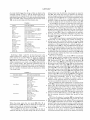
THERMOMETER
BLQDD
msssun:
ted to the remote monitor/controller. The medical treatment
provided to the patient can be changed in response to
analysis of the patient medical data at the remote location.
15 Claims, 13 Drawing Sheets
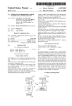
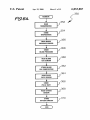
42
/\/1 0
L TELEPHONE F
-
L ‘I'ELEPHQNE
SENSOR
1/36 30
44)’
46f
L MODEM
8:222:58
48
J
52
[I50
p32
—
PULSE RATE
ssuson
OXYGEN
SENSOR
INFUSION
PUMP
:54
58
38
)/1 2
p24
“Mm
MONITOR
CONTROLLER
16
I
£128
22
MODEM V
210
6,053,887
Page 2
US. PATENT DOCUMENTS
4,173,971
11/1979
4,413,314
11/1983 Slater 9t a1~
4,449,538
4,531,527
KarZ ...................................... .. 128/702
5/1984 Corbin 9t 91
7/1985 Reinhold, Jr. et a1.
4,561,443 12/1985 Hogrefe 9t 91
4,586,260
4,624,661
4,676,776
6/1987 HoWson
4,696,671
4,731,051
4,756,706
9/1987 Epstein 9t 91
3/1988 Fischell ........ ..
7/1988 Kems 9t a1~
4,797,840
1/1989 Fraden
4,803,625
2/1989 P11 91 a1- --
4,810,243
4,828,545
3/1989 HoWson
5/1989 Epstein et a1.
4,850,972
7/1989
478657584
9/1989 Epstein et a1_
479017221
4,925,444
3/1995 Kawahara et a1. ...................... .. 604/67
3/1995 Fleitschhackor et a1.
574007246
3/1995
5,412,400
5/1995 Takahara etal. ..................... .. 345/119
-- 128/760
5,429,602
7/1995
128/696
574697855
Hauser ......... ..
11/1995 pompei et aL
604/65
_ 128/664
128/419 PG
5,482,446
1/1996 Williamson et al.
33/125 C
574857408
1/1996 Blomquist ____ __
_ 364/578
.. 604/151
575097422
4/1996 Fukami
_ 128/67O
. 417/474
604/31
5522396
6/1996 Langer eta
_ 128/696
604/67
. 606/67
604/66
5,544,651
575557638
5,573,506
8/1996 Wilk .......... ..
9/1996 Evers et a1_
11/1996 Vasko ..... ..
. 128/633
604/66
604/65
-- 364/557
364/413-03
5,582,593 12/1996 Hultman
5,643,212
.. 604/151
604/65
7/1997 Coutré etal.
604/31
604/66
Schulman et a1.
604/95
Wilson et a1_ ________________________ __ 364/146
~- 364/188
5/1986 Baxter et a1. ..
11/1986 Arimond
5,395,321
5,395,329
. 604/131
OTHER PUBLICATIONS
_ I
_
_
6O4/67
Electronic s Article of Feb., 1990, by Jack Shandle, entitled
2/1990 Kodosky et a1_ _
5/1990 Orkin et a1, ____ __
__ 364/200
604/80
“Who W111 Dommate the Desktop 1n the ’90S,” pp. 48—50.
Chapter 5 entitled “Direct Manipulation” from Shneiderman
4,933,843
4,942,514
4J952J9Z8
6/1990 Scheller et a1.
7/1990 Miyagaki et a1
8/1990 Carroll et a1~ -
364/413.01
“Designing the User Interface: Strategies for Effective
4,995,268
2/1991 Ash et a1.
364/190
Human—Computer Interaction,” Addison—Wesley Publish
340/82554
ing Company, Second Edition, @1992, reprinted With cor
.. 73/861.05
~
5,100,380
571097849
3/1992 Epstein et al.
5/1992 Goodman et aL
604/67
__ 128/633
5,115,133
5/1992 Knudon ........... ..
.. 250/341
5,116,312
5/1992 Blankenship et a1,
5,137,023
8/1992 Mendelson et a1. ..
5,152,296
10/1992
Simons
-------------
604/66
.. 128/633
- - - --
128/670
rections 1993~
Literature of BaXter’s MllltlPlCXTM Series 100 Fluid Man
98mm System 2 PP” no dat‘? hsted' _
_
Literature of Baxter “Introducmg MultlPleXTM Series 100
Fluid Management System,” Copyright 1988
Literature describing BaXter’s Flo—Gard®6201 Volumetric
Infusion Pump, copyrighte 1992.
Literature of I—FloW Corporation advertising its Vivus 4000
5,153,827 10/1992 Coutré etal. ..
364/413.02
531553693 10/1992 Altmayer et a1‘
364/550
One—page article by Jerry Hirsch entitled “Portable IV Frees
'1::111111111111111111111: ‘iii/2Z2
Patients,” printed in The Orange County Register, D Section,
2:123:32‘ 131335 2222255
5,191,891
3/1993
5,207,642 5/1993
5,213,099 5/1993
5,226,425 7/1993
5,230,623 7/1993
5,256,157 10/1993
Righter ......... ..
.. 128/710
Orkin et al. ............................ .. 604/65
Tripp, Jr. ............................... .. 128/633
Righter ..... ..
.. 128/710
Guthrie et a1. .......................... .. 433/72
Samiotes et a1. ..................... .. 604/246
Infusion System
NOV- 21’ 1991'
_
_
Bedder> et all» “cost Analysls of TWO Implantable Narcotlc
Delivery Systems,” Journal Of Pain And Symptom Manage
ment, vol. 6, No. 6, Aug., 1991, pp. 368—373.
Peter Lord, Hossein Allami, Mark Davis, Raul Dias, Patrice
Heck, and Robert Fischell,
from book Chapter
572917190
3/1994 S°ar°1a_ et al- -
340/82506
entitled “MiniMed Technologies Programmable Implantable
5,295,062
5,297,554
3/1994 Fukushlma ............................ .. 364/188
3/1994 Glynn/et a1. .......................... .. 128/665
Infusion System,” describing Clinical trials from NOV‘, 1986'
aalMED®StatusTM Infusion Management System,” 6 page
5,317,506
5/1994
5,338,157
8/1994 Blomquist ................................. .. 417/2
brochure’ IMED corporamn’ San Dlego’ CA’ no date hsted'
5,361,758
11/1994 Hall et al. ............................. .. 128/633
James D- Foley and Andnes Van Dam “Fundamentals of
Coutre et a1. ..
5,368,562 11/1994 Blomquist et a1_
364/413.02
604/65
.
.
.
Interactive Computer Graphics,” selected pages from Chap
5,376,070 12/1994 Pulvis et al. ............................ .. 604/31
ters 1 and 2, Addison—Wesley Publishing Company, @1982,
5,378,231
reprinted With corrections 1983.
1/1995 Johnson et a1. ......................... .. 604/67
U.S. Patent
Apr. 25, 2000
THERMOMETER
F29
42
405 l———{
BLOOD
TELEPHONE
46
f
34
p32
REMOTE
MONITOR
CONTROLLER
EN
OR
158 lL/T 6
/
CATHETER
ROM
f
RAM
64
M__,
I
p24
f
1/0
f
38
r54
56
“is
MODEM
USION
MP
PULSE RATE
SENSOR
10
TELEPHONE
MODEM
moon GAS
SENSOR
6,053,887
Sheet 1 0f 13
66
‘
MP
84
14
7
1
KEYBOARD
I20
U.S. Patent
Apr. 25, 2000
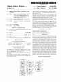
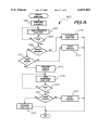
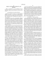
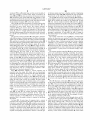
Fig.5.
200
I POWER ON I
6,053,887
Sheet 3 0f 13
>
INITIALIZATION
AND
NO
SELF TEST
5
202
204
RESUME
?
YES
206
ANY
REMAINING
VOL OR TIME
PROGRAM
PCA
DO
LOCKOUT
I__‘
SEQUENCE
PROGSRAM
2
PERIODS
$ I_
232
PROGRAM
INTERMITTENT
PROGRAM
AUTO-RAMP
PROGRAM
CONTINUOUS
K220
210 v +
268
READY
TO RUN
STOP
INFUSION
260\ I
RUN
MODE
A
NO
Y
[264 T_
\\
REPORT
ALARMS
HOLD
KEY
262
\266
‘‘
nun
NO
KEY
YES
‘l
OFF
KEY
?
YES
TURN
OFF
N0
YES 270
U.S. Patent
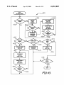
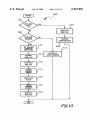
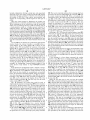
I
RECORD
Apr. 25, 2000
F19. 6.
I
302
PROGRAMMING
COMPLETE
6,053,887
Sheet 4 0f 13
YES
F’
STORE
PROGRAMMED
PARAMETERS
V
STORE RUN
PARAMETERS
STORE TOTAL
VOLUME INFUSEO
STORE TOTAL
CHANGE
VOLUME INFUSED,
NEW RATE, VOLUME
STORE TOTAL
VOLUME INFUSED,
ALARM TYPE
INFUSION
COMPLETE
326
STORE TOTAL
MALFUNCTION
?
VOLUME INFUSEO,
MALFUNCTION
TYPE
RESUME
INFUSION
LOCKOUT
PROGRAMMING
COMPLETE
?
BOLUS
REQUEST
?
STORE TOTAL
VOLUME INFUSEO
STORE RESUMED
PARAMETERS
STORE MODES
LOCKED OUT
YES
STORE
GIVEN / NOT GIVEN,
BOLUS AMOUNT
TV
U.S. Patent
Apr. 25, 2000
Sheet 5 0f 13
6,053,887
350
F29. 6A.
E
352 ;
READ
msnmommn
j
STORE
TEMPERATURE
1354
READ BLO
PRESSURE SE
R
STORE
BLOOD PRESSURE
/356
f
358
360
READ BLOOD
GAS SENSOR
J
smma moon
1362
GAS COMPOSITION
READ PULSE
RATE SENSOR
STORE
PULSE RATE
GEN
R
READ
SE
ST
OXYGEN
TENT
V
END
2/
2/
5
364
366
368
I370
U.S. Patent
Apr. 25, 2000
Sheet 6 0f 13
6,053,887
104
F29. 7.
376
PUMP DATA
PATIENT DATA
I
STORE DATA
/\38o
I
F29. 8.
v
SET POINTER T0
382
1
NEXT ADDRESS
384
IS
POINTER AT
LAST ADDRESS
SET POINTER T0
FIRST ADDRESS
I
WRITE TIME
388
/
STAMP IN LOG
"
WRITE EVENT
DATA IN LOG
V
END
390
/
U.S. Patent
Apr. 25, 2000
Sheet 7 0f 13
6,053,887
402
mm
m SEND
ID REuuEsT
P,‘‘g’ 9'
‘v
mm PUMP
REAu cIIARAcTERs 'j
404
{
410
DETERMINE
406
coRREcT
RESPONSE
—->
PUMP TYPE
‘
ERRoR
MESSAGE
YES
'2
\'\
41 4
TIMER
EXPIRED
?
SEND PUMP
DISPLAY
REuuEsT
READ
CHARACTERS
FROM mm
I416
J/
41 8
424
ERRoR
MESSAGE
DETERMINE
PuMP TYPE
\/\
‘‘
'
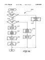
U.S. Patent
(
Apr. 25, 2000
USER
SELECTS MODE
Sheet 8 0f 13
)
6,053,887
/\/45O
Y
cOMMAND
M005
7
452
YES
DISPLAY
PUMP
KEYPAD
—>-
GET PUMP'S
DISPLAY
FROM PUMP
N0
7
SHOW PUMP’S
DISPLAY
ON SCREEN
/
462
TBANSMIT
COMMAND
TO PUMP
EXIT
COMMAND
MODE
?
465
474
MONITOR
MODE
DOWNLOAD
DATA LDG
466
?
DISPLAY PUMP
MDNITDR
467
<
470
DOWNLOAD
DATALDG
VIEW
DATA LOG
V472
GET PUMPS
DISPLAY
FROM PUMP
478
‘Y
,
snow PUMP 5
0" SCREEN
‘ EXIT
MONITOR
MODE
EXIT
MODE
U.S. Patent
Apr. 25, 2000
Sheet 9 0f 13
6,053,887
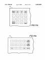
78
F29. 11A.
78
Fig. 118.
U.S. Patent
Apr. 25,2000
Sheet 10 0f 13
6,053,887
458
/"
COMMAND
480
SEN!)
f
PUMP COMMAND
I
READ CHARACTERS
482
FROM PUMP
PUMP ECHO
CORRECT
0
f488
ERROR
MESSAGE
SEND
ACKNOWLEDGEMENT
[490
Fig. 12.
U.S. Patent
Apr. 25,2000
Sheet 11 0f 13
6,053,887
500
502
N
DATA DUMP
AcTlvE
YES
504
?
l
5
RESET DATA
508
DUMP FLAG
DATA DUMP
l
COMMAND
TRANSMIT
ERROR MESSAGE
506
SET TRANSMIT
POINTER T0
51 O
OLIJEST DATA
0
551 DATA
51 4
5
RESPOND T0
OTHER COMMAND
DUMP FLAD
FETCH FIRST
551 6
DATA BYTE
V
UPDATE
TRANSMIT
POINTER
V
FORMAT DATA
j
51 8
55 2 O
m Ascn
V
ENABLE
TRANSMIT
j
522
INTERRUPT
l
SEND FIRST
DATA BYTE
Fig. 13.
U.S. Patent
Apr. 25, 2000
6,053,887
Sheet 12 0f 13
550
TRANSMIT
,m/
DATA DUMP
ACTIVE
N0
l
RESPOND TO
OTHER
INTERRUPT
ALL DATA
SENT
YES
?
FETCH NEXT
554
j
562
DATA BYTE
5 58
l
UPDATE
j 56
4
TRANSMIT
POINTER
l
FORMAT DATA
DISABLE
TRANSMIT
INTERRUPT
l
1
566
RESET DATA
“UMP FLAG
j
550
m Ascn
l
SEND
DATA BYTE
/
568
'
F29’. 14.
U.S. Patent
Apr. 25,2000
Sheet 13 0f 13
6,053,887
F29. 15.
PATIENT NAME:
‘
PATIENT In
BEGINNING
ENDING
NUMBER:
DATE:
DATE:
[3 MALFUNCTIONS AND ALARMS
[I PUMP TuRNEn ON
I] PIGGYBACKS
[j TRERAPIEs PROGHAMMED
I] PUMP TURNED OFF
5 TITRATIONS AND RATECHANGES
[I TRERAPIEs sTARTEn
I] PUMP 0N HOLD
[3 BOLUS sTATus
I] TRERAPIEs COMPLETED
I] PUMP RESTARTED
[I PATIENT IDS
[j TRERAPIEs RESUMED
In ALL DATA
1] INFUSION DATA
gIsPLAY
]
F gRINT
]
I _S_AVE To DISK J
I EXIT _|
6,053,887
1
2
MEDICAL TREATMENT APPARATUS AND
METHOD
Us. Pat. No. 4,803,625 to Fu, et al. also discloses the
concept of providing a patient monitoring apparatus at a
patient location and a remote monitoring device having the
This is a continuation, of prior application Ser. No.
08/703,543, ?led Aug. 27, 1996 now US. Pat. No. 5,895,
321 Which is hereby incorporated herein by reference in its
monitoring apparatus. As shoWn in FIG. 2 of the Fu, et al.
capability of receiving patient medical data from the patient
patent, the patient monitoring apparatus is provided in the
entirety.
BACKGROUND OF THE INVENTION
The present invention is directed to a medical treatment
10
form of a number of home units 60, each of Which includes
a number of sensors, including a blood pressure module 92,
a scale module 84, a temperature module 86, and an ECG
electrode unit 90. Each of the home units 60 is connected to
a central unit 20 via a modem 62 connected to each home
unit 60 and a modem 22 connected to the central unit 20. The
Fu, et al. patent also generates medication reminders to a
apparatus and method for automatically administering a
medical treatment to a patient via a medical treatment
device, such as an infusion pump, disposed at a ?rst location
patient. See, for example, FIG. 13.
and a monitoring and/or controlling device disposed at a
15
remote location.
SUMMARY OF THE INVENTION
An infusion pump is used to automatically administer
The invention is directed to a medical treatment apparatus
liquid medicant to a patient. The liquid medicant is supplied
having programmable medical treatment means for auto
matically administering a medical treatment directly to a
from a source of medicant and pumped into the patient via
a catheter or other injection device. The manner in Which the
liquid is infused is controlled by the infusion pump, Which
20
patient, the programmable medical treatment means being
disposed at a ?rst room location, a sensor for detecting a
may have various modes of infusion, such as a continuous
medical condition of the patient, the sensor being disposed
mode in Which the liquid medicant is continuously infused
at the ?rst room location and being connected to the patient,
and a remote controller for controlling the programmable
medical treatment means, the remote controller being dis
at a constant rate, or a ramp mode in Which the rate of
infusion gradually increases, then remains constant, and then
gradually decreases.
25
posed at a second room location remote from the ?rst room
Prior art systems have been described Which monitor the
medical condition of a patient at a patient location using a
location at Which the programmable medical treatment
sensing apparatus Which has various types of sensors, such
controlling the programmable medical treatment means to
means is disposed. The remote controller includes means for
as a sensor for generating heart rate data and a temperature 30 alloW the medical treatment being administered to the
patient to be changed, and the medical treatment apparatus
also includes remote monitoring means operatively coupled
sensor for monitoring the temperature in the ear canal of the
patient. Such a prior art system included a remote monitor
ing device provided at a location remote from the sensing
apparatus to Which sensing data Was transmitted, and the
remote monitoring device transmitted control signals to the
sensing apparatus at the patient location to control the
to the sensor for monitoring the medical condition detected
by the sensor, the remote monitoring means being disposed
35
operation of the sensing apparatus, such as by controlling the
infusion pump for infusing a drug into the patient, the
infusion pump being composed of a liquid injection device
sampling rate of the sensors. Such a prior art system also
included display means at the remote location for generating
visual displays relating to the sensed medical conditions.
One eXample of such a prior art system is disclosed in
US. Pat. No. 3,910,257 to Fletcher, et al. That patent
adapted to be connected to the patient, a conduit connected
40
to the liquid injection device, a pumping mechanism for
pumping a liquid drug through the conduit and into the
patient via the liquid injection device, and a controller for
controlling the pumping mechanism.
discloses a sensing apparatus in the form of a bio-belt unit
11, 12 and a remote monitoring device in the form of a data
acquisition unit 14. The bio-belt unit 11, 12 incorporates
at the second room location.
The programmable medical treatment means may be an
45
The invention is also directed to a method of administer
ing a medical treatment to a patient via a programmable
medical treatment apparatus. The method includes the steps
of: (a) automatically administering a medical treatment to a
patient With a programmable medical treatment apparatus
disposed at a ?rst room location, (b) detecting a medical
different types of sensors, including an ear canal sensor 21
and a plurality of ECG electrodes 22. The data acquisition
unit 14 receives patient medical data from the bio-belt unit
11, 12 and also transmits control commands to control the
operation of the bio-belt unit 11, 12. See eg FIG. 2; column
condition of the patient With a sensor at the ?rst room
5, lines 1—7; column 6, lines 6—10; and column 6, lines
location, (c) transmitting medical condition data relating to
39—47 of the Fletcher, et al. patent.
US. Pat. No. 5,038,800 to Oba also discloses the concept
of providing a patient monitoring apparatus at a patient
location and a remote monitoring device having the capa
the medical condition from the ?rst room location to a
second room location, and (d) transmitting a control com
mand from the second room location to the programmable
55
patient monitoring apparatus from a remote location. The
patient monitoring apparatus is provided as a number of
bedside monitors 3A—3C, and the remote monitoring appa
ratus is provided is in the form of a central monitor 2. The
Oba patent discloses that the bedside monitors 3A—3C and
60
on a visual display disposed at the second room location, and
of a remote monitor/controller disposed at the second room
The operation of the bedside monitors
3A—3C can be controlled from the central monitor 2. See, for
example, column 4, lines 4—11; column 4, lines 24—27; and
column 4, lines 40—42 of the Oba patent.
The method may also include the step of analyZing the
medical condition data prior to transmitting the control
command, the step of displaying the medical condition data
the step of storing the medical condition data in the memory
the central monitor 2 are interconnected via a local area
netWork
medical treatment apparatus at the ?rst room location to
change the medical treatment automatically administered
during step (a), the control command being based upon the
medical condition data transmitted during step
bility of receiving patient medical data from the patient
monitoring apparatus and controlling the operation of the
65
location.
These and other features and advantages of the present
invention Will be apparent to those of ordinary skill in the art
6,053,887
3
4
in vieW of the detailed description of the preferred
embodiment, Which is made With reference to the drawings,
a brief description of Which is provided below.
36. The tWo modems 22, 30 are interconnected to bidirec
tional voice and data communication via a communication
link 38, Which could be a telephone line, for eXample.
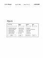
The infusion pump 12 is connected to ?ve conventional
sensors Which are connected to the patient and Which detect
BRIEF DESCRIPTION OF THE DRAWINGS
various medical conditions of the patient. The sensors
include a thermometer 40 connected to the infusion pump 12
FIG. 1 is a block diagram of an apparatus for adminis
tering medical treatment to a patient and monitoring the
condition of the patient;
FIG. 2 is a block diagram of the electronic components of
the remote monitor/controller shoWn schematically in FIG.
10
1;
FIG. 3 is a front vieW of one embodiment of the infusion
40, 44, 48, 52, 56 are required for operation of the apparatus
pump shoWn schematically in FIG. 1;
FIG. 4 is a block diagram of the electronic components of
the infusion pump of FIG. 3;
FIG. 5 is a ?oWchart of the overall operation of the
infusion pump;
FIG. 6 illustrates a number of data-recording steps per
15
(I/O) circuit 66, all of Which are interconnected by an
address/data bus 68. The microprocessor 60 has a transmit
buffer (XMIT) 70 for transmitting data bytes and a receive
FIG. 6A is a ?oWchart of a routine for storing patient
condition data generated by the sensors of FIG. 1;
buffer (REC) 72 for receiving data bytes. The remote
25
FIG. 8 is a ?oWchart of a store data routine Which can be
used to store data relating to the operation of the infusion
pump and data relating to the condition of a patient;
FIG. 9 is a ?oWchart of a routine Which may be used to
monitor/controller is coupled;
pump 12 shoWn schematically in FIG. 1. Referring to FIG.
3, the pump 12 has an input device in the form of a keypad
FIG. 10 is a ?oWchart of a main operating routine of the
35
generated by the remote monitor/controller;
FIG. 12 is a ?oWchart of a command pump routine that is
performed by the remote monitor/controller;
FIG. 13 is a ?oWchart of a receive routine that is per
interface 102a, a nonvolatile RAM 104, a real-time clock
FIG. 14 is a ?oWchart of a transmit routine that is
106 and the display 92, all of Which are interconnected by
performed by the infusion pump; and
a communications bus 108. The display 92 has a backlight
FIG. 15 is an illustration of a graphical user menu that
110 Which is selectively activated by an enable signal
45
DETAILED DESCRIPTION OF A PREFERRED
EMBODIMENT
The controller 100 controls the medicant infusion rate by
periodically transmitting a control signal to an ampli?er
ratus 10 includes a programmable medical treatment means
Which is disposed at a room location remote from the room
location at Which the infusion pump 12 is located. The
remote monitor/controller 20 could be disposed in a different
room of the same building in Which the pump 12 is disposed,
or in a different building than the one in Which the pump 12
is disposed. The remote monitor/controller 20 is connected
generated on a line 112 interconnecting the controller 100
and the backlight 110. Both the RAM 104 and the real-time
clock 106 are connected to a battery 114 Which supplies
poWer to them only in the absence of system poWer. The
controller 100 has a transmit buffer 116 and a receive buffer
118 connected to the communications bus 108.
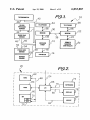
FIG. 1 illustrates one embodiment of an apparatus 10 for
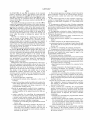
administering medical treatment to a patient and monitoring
the condition of the patient. Referring to FIG. 1, the appa
in the form of an infusion pump 12, Which is connected to
a liquid medicant injection device in the form of a catheter
14 via a liquid conduit schematically shoWn as 16.
The apparatus 10 includes a remote monitor/controller 20
90 via Which a user may input data and commands and a
display 92 for displaying teXtual messages to the user.
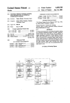
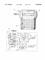
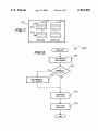
A block diagram of the electronics of the infusion pump
12 is shoWn in FIG. 4. Referring to FIG. 4, the pump 12
includes a controller 100, an electrically programmable
read-only memory (EPROM) 102 having a built-in I/O
formed by the infusion pump;
may be displayed by the remote monitor/controller.
monitor/controller 20 has a keyboard 74 connected to the
I/O circuit 66 via a line 76, a display device 78, such as a
CRT, connected to the I/O circuit 66 via a line 80, and an
input device, such as an electronic mouse 82, connected to
the I/O circuit 66 via a line 84. The remote monitor/
controller 20 can also include one or more disk drives, such
as a hard disk drive or a ?oppy disk drive.
FIG. 3 is a front vieW of one embodiment of the infusion
identify the type of infusion pump to Which the remote
remote monitor/controller;
FIGS. 11A—11B illustrate portions of visual displays
10, and other types of sensors could be used.
FIG. 2 is a block diagram of the electronics of the remote
monitor/controller 20 shoWn schematically in FIG. 1. Refer
ring to FIG. 2, the remote monitor/controller 20 includes a
microprocessor (MP) 60, a read-only memory (ROM) 62, a
random-access memory (RAM) 64, and an input/output
formed during the operation of the infusion pump;
FIG. 7 is a representation of a portion of the memory of
the infusion pump;
via a line 42, a blood pressure sensor 44 connected to the
pump 12 via a line 46, a blood gas sensor 48 connected to
the pump 12 via a line 50, a pulse rate sensor 52 connected
to the pump 12 via a line 54, and a blood-oxygen sensor 56
connected to the pump 12 via a line 58. Not all of the sensors
circuit 120 via a line 122 to drive a pump motor 124 Which
drives a pumping mechanism 126, such as a rotary pump
55
Wheel (not shoWn) adapted to make contact With a portion of
the liquid conduit 16 (FIG. 1) connected to the catheter 14.
The controller 100 receives periodic inputs from a shaft
encoder (SE) sensor 130, Which is disposed on the shaft of
the motor 124. The SE sensor 130 may be a tWo-phase
motion sensing encoder Which provides tWo signal outputs
to the controller 100. The rotational speed of the motor 124
and its direction of rotation are determined by the controller
100 based upon the rate and phase relationship betWeen the
to a conventional voice/data modem 22 via a data link 24,
tWo signal outputs.
and the modem 22 is also connected to a telephone 26 via a
voice link 28. The infusion pump 12 is connected to a 65
The SE encoder 130 periodically transmits the signals to
the controller 100 via a line 132. Each time the signals are
conventional voice/data modem 30 via a data link 32, and
the modem 30 is connected to a telephone 34 via a voice link
transmitted, an interrupt is generated, and the controller 100
6,053,887
5
6
compares the actual position of the motor shaft With its
threshold rate, stays constant at the threshold rate, and then
desired position, and transmits a neW control signal, such as
gradually decreases; 3) an intermittent mode in Which the
pump delivers discrete liquid volumes spaced over relatively
long periods of time, such as a liquid volume every three
a pulse-Width modulated signal, to the ampli?er 120 via the
line 122 to ensure that the actual speed of the motor 124
corresponds to the motor speed required for the desired
medicant infusion rate. The interrupts caused by the SE
sensor 130 are assigned to the highest priority so that they
hours; 4) a custom mode in Which the pump can be pro
grammed to deliver a unique infusion rate during each of 25
different time periods; and 5) a pain-controlled analgesic
(PCA) mode during Which the pump Will periodically infuse
boluses of analgesic in response to periodic requests by the
are responded to immediately, before any other actions are
taken by the controller 100.
The pump 12 has a number of other features not described
10
herein, Which are disclosed in the folloWing patent
patient.
At step 218, the pump 12 generates on the display 92 the
applications, each of Which is incorporated herein by refer
prompt “Continuous?” to the user. If the user desires to use
ence: U.S. Ser. No. 08/399,184, ?led Mar. 6, 1995, entitled
the pump in its continuous mode, the user ansWers “yes” via
“Infusion Pump Having PoWer Saving Modes”; U.S. Ser.
No. 08/398,977, ?led Mar. 6, 1995, entitled “Infusion Pump
15
the keypad 90, and the program branches to step 220 at
Which the continuous mode is programmed by the user by
20
entering a number of infusion parameters, such as the
desired infusion rate, the volume to be infused, etc. At step
218, if the user does not Want to use the continuous mode,
the user ansWers “No,” and the program branches to step
222. Steps 222—236 are generally the same as steps 218 and
With Selective Backlight”; U.S. Ser. No. 08/398,980, ?led
Mar. 6, 1995, entitled “Infusion Pump With Different Oper
ating Modes”; U.S. Ser. No. 08/398,886, ?led Mar. 6, 1995,
entitled “Cassette For An Infusion Pump; U.S. Ser. No.
08/399,183, ?led Mar. 6, 1995, entitled “Infusion Pump
With Dual-Latching Mechanism”; U.S. Ser. No. 08/398,887,
?led Mar. 6, 1995, entitled “Infusion Pump With Historical
Data Recording.”
The operation of the infusion pump 12 is controlled by a
computer program stored in the EPROM 102 and eXecuted
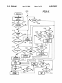
by the controller 100. A ?oWchart 200 of the overall opera
tion is illustrated in FIG. 5. Referring to FIG. 5, When the
pump 12 is turned on, at step 202 the pump is initialiZed and
a test of the pump operation is performed. The pump 12 may
be turned off temporarily during an infusion, in Which case
the pump 12 may continue the infusion When it is turned
back on, as described beloW. At step 204, if there is any
remaining volume of liquid to be infused by the pump or any
additional time remaining for an infusion, Which Would be
the case Where the pump Was temporarily turned off during
an infusion, the program branches to step 206, Where the
user is asked, via a message displayed on the display 92,
Whether the previous infusion should be resumed. If the user
ansWers yes (via the keypad 90), the program branches to a
ready-to-run step 210. If the previous infusion is not to be
resumed, the program branches to step 212.
The infusion pump 12 has a lockout mode in Which the
user may be prevented from programming the infusion
25
30
220, eXcept that the user may be prompted for different
infusion parameters, depending on Which of the ?ve possible
infusion modes is selected.
After the completion of one of the steps 220, 224, 228,
232, or 236, the program branches to the ready-to-run step
210. When the user presses the “Run” key, the pump 12
enters the run mode 260 and infuses the patient With a liquid
medicant in accordance With the infusion mode selected at
one of steps 218, 222, 226, 230, 234 and the infusion
parameters entered at one of steps 220, 224, 228, 232, 236.
The pump 12 remains in the run mode 260 until the “Hold”
key is pressed, as determined at step 262. Upon the occur
rence of an alarm condition, an alarm is reported at step 264.
35
At step 262, if the hold key is pressed, the infusion is stopped
at step 266, and the pump 12 Waits for the run key to be
pressed at step 268 or the on/off sWitch to be turned off at
step 270.
SummariZing the operation described above, if the pump
40
is to be utiliZed in lockout mode, a medical assistant turns
the pump on, programs the desired infusion mode at one of
steps 220, 224, 228, 232, 236, and then turns the pump off.
The programmed infusion parameters Will be retained in the
memory 104. The medical assistant Would then turn the
parameters, such as the volume to be infused or the rate of 45 pump back on, press the “No” key in response to the
“Programmable?” prompt at step 214, enter the lockout
information at step 216, and then turn the pump off again.
When the patient subsequently turned on the pump to
infusion. For eXample, the pump 12 could be programmed
by a medical assistant to deliver a particular infusion having
a particular ?oW pro?le, ?oW rate and volume to be infused.
perform the infusion, the program Would proceed from step
212 directly to the ready-to-run step 210, Which Would
prevent the patient from altering the infusion parameters.
After programming that infusion, the medical assistant could
place the pump in lockout mode, Which Would prevent the
patient from changing any of the infusion parameters. At
step 212, if the pump 12 has been previously placed in
lockout mode, the program branches directly to the ready
If the lockout mode Was not utiliZed, the medical assistant
or the patient could turn the pump on, program the desired
to-run step 210, bypassing all programming steps.
At step 212, if the pump is not in lockout mode, the
program branches to step 214, at Which point the program
prompts the user, via the display 92, to input Whether the
patient should be alloWed to program the pump during the
subsequent infusion. If the pump is not to be programmable,
55
the program branches to step 216 Where a lockout sequence
60
infusion mode, and then press the “Run” key to start the
infusion Without ever turning the pump off.
During programming and operation, the infusion pump 12
automatically records in the non-volatile memory 104 all
signi?cant infusion data to generate a complete historical
data record Which can be later retrieved from the memory
is performed by requesting the user to input Which infusion
104 and used for various purposes, including clinical pur
poses to aid in determining hoW effective a particular
modes should be locked out. If the pump is to be program
infusion therapy Was and treatment purposes to con?rm that
mable by the patient, the program bypasses step 216.
volume at a single rate; 2) an auto-ramp mode in Which the
the prescribed infusion Was actually delivered.
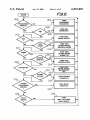
FIG. 6 illustrates various steps at Which infusion data is
recorded that are performed during the overall pump opera
tion shoWn generally in FIG. 5. The infusion data recorded
pump delivers liquid at a rate that gradually increases to a
in the memory 104 is set forth in Table 1 beloW. A number
The infusion pump 12 has ?ve basic modes of infusion: 1)
a continuous mode in Which the pump delivers a single 65
6,053,887
7
8
of events Which trigger the storage of data are listed in the
left-hand column of Table 1, and the infusion data that is
recorded upon the occurrence of each event is listed in the
right-hand column of Table 1. The time at Which the infusion
infused at the time the hold key Was pressed are stored at
step 312. The pump also stores any infusion rate changes,
such as changes caused by sWitching from a continuous rate
to a keep-vein-open (KVO) rate, or in the intermittent mode,
changing from a KVO rate to a higher infusion rate, the
presence of Which are detected at step 314. The neW rate and
the time at Which the neW rate started are stored at step 316.
data is recorded, Which is determined by the real-time clock
106, is also stored along With the infusion data.
TABLE 1
EVENT
DATA RECORDED
Power On
Date and Time
Program
Infusion parameters. See TABLE 2.
Run
Hold
Restart
Infusion parameters. See TABLE 2.
Total Volume Infused
Time of Restart
Rate Changes
Alarms
Infusion Complete
Malfunctions
Total
Total
Total
Total
Volume
Volume
Volume
Volume
Infused, Rate, Volume
Infused, Alarm Type
Infused
Infused, Malfunction
At step 318, if any alarms are generated, the alarm type,
the time at Which the alarm occurred, and the total volume
infused at the time of the alarm are recorded at step 320. If
the infusion is completed as determined at step 322, the
program branches to step 324 Where the time at Which the
infusion Was completed is stored along With the total volume
infused. At step 326, if there is a malfunction, the malfunc
15 tion type, the time at Which the malfunction occurred, and
10
the total volume infused at the time of the malfunction are
recorded at step 328.
At step 330, if the infusion is resumed (When the pump is
Type
Resume
Maintenance Date
Patient ID
Serial No.
Infusion parameters. See TABLE 2.
Date
Patient ID Number
Serial Number
turned back on after having been turned off during an
20
Language Change
New Language
infusion), the time at Which the infusion is resumed along
With the infusion parameters are stored at step 332. Upon the
completion of the programming of a lockout sequence as
Lockout
Modes Locked Out
determined at step 334 (i.e. after step 216 of FIG. 5), the time
Pressure Select
New Pressure Setting
Bolus Request
Given/Not Given, Bolus Amount
Titration
PoWer Off
Version No.
NeW Parameters
Time of PoWer Off
Software Version Number
at Which the programming of the lockout Was completed is
stored along With the infusion modes that Were locked out.
At step 338, upon the detection of a bolus request, the time
at Which the bolus Was requested is stored at step 340, along
With an indication Whether the bolus Was actually given and
the amount of the bolus.
Referring to Table 1 and FIG. 6, When the poWer to the 30
FIG. 6A is a ?oWchart of a routine 350 for periodically
infusion pump 12 is turned on, the date and time of the
storing
patient medical condition data generated by the
poWer turn-on is recorded. When the pump is completely
25
programmed pursuant to one of steps 220, 224, 228, 232,
236 (FIG. 5) as determined at step 302, the programmed
infusion parameters are stored at step 304, along With the
time of such storage. The particular parameters that are
stored depend upon Which infusion mode Was programmed.
Several examples of infusion parameters that are stored for
35
sensors 40, 44, 48, 52, 56 of FIG. 1 in the nonvolatile RAM
104. Referring to FIG. 6A, at step 352 the thermometer 40
is read, and at step 354 data generated by the thermometer
40 is stored in the RAM 104. At step 356 the blood pressure
sensor 44 is read, and at step 358 data generated by the
sensor 44 is stored in the RAM 104. At step 360 the blood
each of a number of infusion modes are illustrated in Table
2 set forth beloW.
gas sensor 48 is read, and at step 362 data generated by the
sensor 48 is stored in the RAM 104. At step 364 the pulse
rate sensor 52 is read, and at step 366 data generated by the
TABLE 2
sensor 52 is stored in the RAM 104. At step 368 the blood
oxygen sensor 56 is read, and at step 370 data generated by
INFUSION MODE
INFUSION PARAMETERS
Continuous
Infusion Mode
Infusion Rate
Volume To Be Infused
the sensor 56 is stored in the RAM 104. The routine 350 may
45
utiliZed, and the particular manner in Which the sensors are
Delay Time
read is not considered important to the invention.
FIG. 7 illustrates the data organiZation of a portion of the
Total Bag Volume
KVO Rate
Auto-Ramp
RAM 104 in Which infusion data (the data stored during the
steps of FIG. 6) and patient medical condition data (the data
stored during the steps of FIG. 6A) are stored. Referring to
Infusion Mode
Infusion Rate
Volume To Be Infused
Delay Time
FIG. 7, the infusion data is stored in a number of memory
locations 372, and the medical condition data is stored in a
number of memory locations 374. Data may be Written to the
Total Bag Volume
Duration of Up-Ramp
Duration of Down-Ramp
KVO Rate
Intermittent
55
Infusion Mode
Total Infusion Time
Number of Doses
Dose Time
Dose Volume
KVO Rate
When the pump enters the run mode 260 (FIG. 5) as
determined at step 306, the time at Which the run mode Was
begun, along With the parameters pursuant to Which the
infusion is performed, are stored at step 308.
At step 310, if the hold key is pressed, then the time at
Which the hold key Was pressed along With the total volume
be performed periodically, such as every minute for
eXample. Other Ways of reading the sensors could be
65
memory locations 372 utiliZing a pointer 376 Which speci
?es the memory location at Which data should be neXt
stored.
FIG. 8 is a ?oWchart of a routine 380 for storing data in
the memory locations 372, 374. Referring to FIG. 8, at step
382 the pointer 376 is set to the address of the neXt memory
location 372 in Which data is to be stored. At step 384, if the
pointer 376 is at the last memory location in Which data may
be stored, the routine branches to step 386 Where the pointer
is set to the address of the ?rst memory location in Which
data may be stored. As a consequence of steps 384, 386, the
contents of the memory locations 372 are periodically
overWritten With neW data; hoWever, the number of memory
6,053,887
9
10
locations 372 is suf?ciently large so that several months of
of infusion pump may have a display capable of displaying
32 characters. Steps 416—426 determine the type of infusion
data, for example, is stored before being overwritten. At
steps 388 and 390 the data is stored in the memory location
pump based on the number of characters in the display.
At step 416, the remote monitor/controller 20 transmits a
pump display request to the infusion pump 12 to request the
pump 12 to transmit the content of its display 92. At step
372 speci?ed by the pointer 376 (the data includes a time
stamp generated from the real-time clock 106 and event data
specifying the particular infusion event). Data may be stored
in the memory locations 374 in the same manner.
418, the remote monitor/controller 20 reads the display
FIGS. 9, 10, and 12 are ?oWcharts of various routines that
are performed by the remote monitor/controller 20. As
described in more detail beloW, the remote monitor/
controller 20 may be used to monitor the operation of the
infusion pump 12, to control the operation of the infusion
pump 12, and/or to transfer infusion data and patient data
characters transmitted from the pump 12. At step 420, if a
10
predetermined period of time has elapsed or if a terminating
character is received, the routine branches to step 422. At
step 422, if the predetermined time period measured by the
timer elapsed prior to the receipt of a terminating character,
the routine branches to step 424 Where an appropriate error
from the infusion pump 12 so that such data can be revieWed
message is generated. At step 426, the type of pump is
by a health care professional at a location remote from the 15 determined based on the number of display characters that
patient.
The remote monitor/controller 20 is designed to interface
With different types of infusion pumps. In order to determine
Which type of infusion pump the remote monitor/controller
20 is operatively coupled, a pump identi?cation routine 400
performed after the communication link betWeen the remote
monitor/controller 20 and the infusion pump 12 is estab
lished. Referring to FIG. 9, at step 402 the remote monitor/
controller 20 transmits a pump identi?cation (ID) request to
the infusion pump 12 via the communication link 38. In
Were received.
The routine could also exit step 420 if a predetermined
number of characters are received. In that case, Where the
remote monitor/controller 20 Was designed to interface With
tWo different types of infusion pumps, one having a display
capability of 12 characters and another having a display
capability of 32 characters, if the remote monitor/controller
20 received more than 12 display characters at step 420, it
Would immediately be able to determine that the pump type
25
The remote monitor/controller 20 alloWs four basic func
tions to be performed, including controlling the infusion
pump 12, monitoring the operation of the pump 12, trans
ferring infusion data and patient medical condition data from
pump. At step 404, the remote monitor/controller 20 reads
the pump 12 to the remote monitor/controller 20, and
vieWing the data. The user may perform one of those
the characters sent from the pump 12 until all characters are
received as determined at step 406 or until a predetermined
time period, eg ?ve seconds, elapses. The time period may
be determined by a timer (not shoWn). The remote monitor/
functions by selecting an operational mode displayed on the
display device 78 (FIG. 2) of the remote monitor/controller
35
controller 20 may determine that all characters have been
received by, for example, identifying one or more termina
tion characters, such as a carriage-return character <CR>
folloWed by a line-feed character <LF>.
Step 408 determines Whether a correct response Was
received from the pump 12, Which may be determined
checking the characters received from the pump 12 against
a list of possible ID codes. If a correct response Was
received, the routine branches to step 410 Where the pump
type is determined, for example, by comparing the received
45
pump ID code With at least one possible ID code Which
identi?es a particular type of infusion pump, or by compar
ing the received pump ID code With a number of possible ID
codes, each of Which identi?es a particular type of infusion
pump. As used herein, the “type” of infusion pump may
relate to the model of the pump or the softWare version of the
pump.
20 via the mouse 82. These modes include a command mode
in Which a health care professional at the remote monitor/
controller 20 may transmit command signals to the infusion
pump 12 to control its operation, a monitoring mode in
Which the infusion pump 12 Will continually transmit the
contents of its visual display 92 to the remote monitor/
controller 20, a doWnload data mode in Which infusion data
and/or patient medical condition data is transferred from the
pump 12 to the remote monitor/controller 20, and a vieW
data mode in Which the infusion data and patient data may
be vieWed on the display 78 of the remote monitor/controller
20.
FIG. 10 illustrates a ?oWchart 450 of the basic operation
of the remote monitor/controller 20. Referring to FIG. 10, at
step 452, if the user selected the command mode described
above, the routine branches to step 454 Where a display of
the keypad 90 of the infusion pump 12 is shoWn on the
display device 78. The display shoWn at step 454 comprises
a plurality of virtual entry keys having a spatial con?gura
If a correct response Was not received as determined by
step 408, at step 412 the routine determines Whether the
predetermined time period measured by the timer has
corresponded to a pump With a 32-character display capa
bility.
response to the pump ID request, the pump 12 transmits a
multi-character ID code back to the remote monitor/
controller 20. The ID code may include, for example, one or
more characters identifying the pump model and/or one or
more characters identifying the softWare version of the
55
tion substantially the same as the entry keys of the keypad
90 of the particular infusion pump type Which is connected
expired prior to receiving a termination character. If so, the
to the remote monitor/controller 20. An example of such a
routine branches to step 414 Where an error message is
visual display is shoWn in FIG. 11A.
It should be noted that the virtual keypad shoWn in FIG.
generated due to the pump’s failure to respond to the pump
ID request.
At step 412, if some type of response (not a correct
response) Was received before the timer expired, the routine
branches to step 416. Steps 416—426 comprise a second Way
of determining the type of infusion pump 12 connected to
the remote monitor/controller 20, Which is based on the
number of characters in the display 92 of the pump 12. For
example, a ?rst type of infusion pump may have a display
capable of displaying 12 characters, Whereas a second type
11A is the same as the actual keypad 90 of the pump 12,
65
Which is shoWn in FIG. 3 (except that the on/off key of the
pump 12 is replaced With a reset key in the virtual key
display). Where a different type of pump having a different
keypad is attached to the remote monitor/controller 20, that
particular keypad is displayed on the display device 78. An
example of a different virtual keypad is shoWn in FIG. 11B.
Various virtual keypad con?gurations may be stored in the
memory of the remote monitor/controller 20, each virtual
![CATHETER] l4](http://vs1.manualzilla.com/store/data/005800484_1-96ddef239138aa0bf6f1f198133819de-150x150.png)