1
YGE-Z 60 Cell Series PV Modules
Installation Supplement
Yingli Solar
Based on Zep Solar Document No.
800-1444-001 Rev F
File Generated April 9, 2014
YGE-Z 60 CEL L SERI ES PV M O DULES INSTAL LA TION S UPP LEMENT
Notices
This manual contains important installation instructions for the core hardware components
required for mounting Zep Compatible™ PV arrays.
WARRANTY VOID IF NON-ZEP-CERTIFIED HARDWARE IS ATTACHED TO GROOVE IN
MODULE FRAME.
This supplement applies to YGE-Z 60 Cell Series PV Modules photovoltaic modules manufactured
by Yingli Green Energy Holding Co., Ltd. ("Yingli Solar") and is explicitly written for qualified professionals ("Installer" or "Installers"), including without limitation licensed electricians and NABCEPCertified PV Installers. This document is intended to serve as a supplement to the Installation
and User Manual from Yingli Solar. All of the information in the Installation and User Manual
also applies to YGE-Z Series PV modules. YGE-Z 60 Cell Series PV Modules modules feature a
Zep compatible groove in the aluminum frame to which hardware manufactured by Zep Solar, Inc.
is directly connected.
For detailed instructions about the design and assembly of Zep Compatible systems, refer to the
Zep Solar installation support tools available online at www.zepsolar.com.
© 2014/EN. Yingli Green Energy Holding Co., Ltd. reserves the right to make specifications changes without prior notice.
YINGLISOLAR.COM/US
File Generated April 9, 2014
Based on Zep Solar Document #800-1444-001 Rev F
Page 2
YGE-Z 60 CEL L SERI ES PV M O DULES INSTAL LA TION S UPP LEMENT
Contents
1
Zep System Layout Dimensions _________________________________________ 5
1.1
Array Layouts, 50 psf (2400 Pa) Design Load............................................................................................................ 6
1.2
Array Layouts, 112 psf (5400 Pa) Design Load.......................................................................................................... 8
2
Zep Compatible™ ______________________________________________________ 9
2.1
Zep Groove and Rockit ......................................................................................................................................................... 9
2.2
Key and Tongue....................................................................................................................................................................10
3
Component Installation _______________________________________________ 11
3.1
Interlock Installation ........................................................................................................................................................ 11
3.2
Ground Zep Installation.................................................................................................................................................... 17
3.3
Cam Foot Installation ....................................................................................................................................................... 18
3.4
Leveling Foot Installation................................................................................................................................................20
4
Array Bonding _______________________________________________________ 22
4.1
Grounding Path Examples................................................................................................................................................ 22
© 2014/EN. Yingli Green Energy Holding Co., Ltd. reserves the right to make specifications changes without prior notice.
YINGLISOLAR.COM/US
File Generated April 9, 2014
Based on Zep Solar Document #800-1444-001 Rev F
Page 3
YGE-Z 60 CEL L SERI ES PV M O DULES INSTAL LA TION S UPP LEMENT
© 2014/EN. Yingli Green Energy Holding Co., Ltd. reserves the right to make specifications changes without prior notice.
YINGLISOLAR.COM/US
File Generated April 9, 2014
Based on Zep Solar Document #800-1444-001 Rev F
Page 4
YGE-Z 60 CEL L SERI ES PV M O DULES INSTAL LA TION S UPP LEMENT
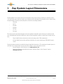
1
Zep System Layout Dimensions
Zep Compatible™ PV modules have been evaluated for design loads of 50 psf (2400 Pa) on the back surface
(e.g., wind load) and on the front surface (e.g., wind and snow load) with the following Zep Solar solutions when
installed with the Interlock and Leveling Foot or Cam Foot mounting hardware:
•
ZS Comp
•
ZS Tile
•
ZS Span
•
ZS Wave
•
ZS Trap
•
ZS Seam
The array layouts on the following pages show the maximum allowable spans and range of cantilevers that
were evaluated with Zep Solar hardware in order for Zep Compatible modules to obtain the following load ratings:
•
50 psf (2400 Pa) front-side and rear-side load rating, per UL 1703 requirements
•
112 psf (5400 Pa) front-side and 50 psf (2400 Pa) rear-side load rating, per IEC 61215 requirements
Zep Solar hardware must be installed following all applicable instructions. The maximum allowable spans for
each Zep Solar solution based on project and site conditions can be obtained as follows:
•
Use the Zepulator online design tool at www.zepulator.com
•
Refer to the Engineering Certification Letters and Span Tables on the “Support” page at
www.zepsolar.com
© 2014/EN. Yingli Green Energy Holding Co., Ltd. reserves the right to make specifications changes without prior notice.
YINGLISOLAR.COM/US
File Generated April 9, 2014
Based on Zep Solar Document #800-1444-001 Rev F
Page 5
YGE-Z 60 CEL L SERI ES PV M O DULES INSTAL LA TION S UPP LEMENT
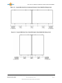
1.1 Array Layouts, 50 psf (2400 Pa) Design Load
Figure 1.1 Layout With Leveling Feet, Landscape Example, 50 psf (2400 Pa) Design Load
Figure 1.2 Layout With Leveling Feet, Portrait Example, 50 psf (2400 Pa) Design Load
© 2014/EN. Yingli Green Energy Holding Co., Ltd. reserves the right to make specifications changes without prior notice.
YINGLISOLAR.COM/US
File Generated April 9, 2014
Based on Zep Solar Document #800-1444-001 Rev F
Page 6
YGE-Z 60 CEL L SERI ES PV M O DULES INSTAL LA TION S UPP LEMENT
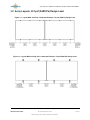
Figure 1.3 Layout With Cam Feet, Landscape Example, 50 psf (2400 Pa) Design Load
Figure 1.4 Layout With Cam Feet, Portrait Example, 50 psf (2400 Pa) Design Load
© 2014/EN. Yingli Green Energy Holding Co., Ltd. reserves the right to make specifications changes without prior notice.
YINGLISOLAR.COM/US
File Generated April 9, 2014
Based on Zep Solar Document #800-1444-001 Rev F
Page 7
YGE-Z 60 CEL L SERI ES PV M O DULES INSTAL LA TION S UPP LEMENT
1.2 Array Layouts, 112 psf (5400 Pa) Design Load
Figure 1.5 Layout With Cam Feet, Landscape Example, 112 psf (5400 Pa) Design Load
Figure 1.6 Layout With Leveling Feet, Landscape Example, 112 psf (5400 Pa) Design Load
© 2014/EN. Yingli Green Energy Holding Co., Ltd. reserves the right to make specifications changes without prior notice.
YINGLISOLAR.COM/US
File Generated April 9, 2014
Based on Zep Solar Document #800-1444-001 Rev F
Page 8
YGE-Z 60 CEL L SERI ES PV M O DULES INSTAL LA TION S UPP LEMENT
2
Zep Compatible™
Zep Solar mounting solutions are based on the Zep Groove, a patented module frame profile
designed to mate easily and precisely with Zep components. Module frames with the Zep Groove
are considered "Zep Compatible", and are manufactured according to specifications determined by
Zep Solar, Inc.
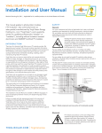
2.1 Zep Groove and Rockit
Figure 2.1 Zep Groove and Rockit
Tongue side
Key side
Zep Groove cross
section
Zep Groove
Zep Compatible PV module
Zep Compatible PV module
Rockit
One example of Zep Compatible hardware mating is the “Rockit”. The Rockit is
a hardware feature used to secure PV modules to the roof attachments. The
Rockit fits into the Zep Groove on both sides: The Key side inserts, while the
Tongue side receives.
The Rockit is used in several Zep Solar hardware components, including the
Cam Foot and the Leveling Foot.
© 2014/EN. Yingli Green Energy Holding Co., Ltd. reserves the right to make specifications changes without prior notice.
YINGLISOLAR.COM/US
File Generated April 9, 2014
Based on Zep Solar Document #800-1444-001 Rev F
Page 9
YGE-Z 60 CEL L SERI ES PV M O DULES INSTAL LA TION S UPP LEMENT
2.2 Key and Tongue
The Key and Tongue concept informs all Zep Compatible designs. The Key side inserts into the Zep
Groove, similar to inserting a key into a lock. On the other side, the Zep Groove allows PV modules
to “drop in” easily onto the Tongue side.
2.2.1 Key and Tongue: Module Drop-In on Rockit
Figure 2.2 Module Drop-In Example
2
1
First, the Key side of the Rockit
is inserted into the Zep Groove.
3
4
In the next row, modules are “dropped in” on the Tongue side (the receiving
side). Each Tongue provides an in/out adjustability with the Zep Groove, allowing for optimized placement of each module.
2.2.2 Key and Tongue: Interlock
Another example of the use of Key and Tongue in a Zep Compatible design is seen with the Interlock, a component that couples and bonds two modules together. Here, the Key and Tongue are
differently shaped, but they still fit into the Zep Groove in the same manner as the Rockit.
Figure 2.3 Interlock, Key and Tongue Side Views
Interlock Tongue side
Interlock Key side
© 2014/EN. Yingli Green Energy Holding Co., Ltd. reserves the right to make specifications changes without prior notice.
YINGLISOLAR.COM/US
File Generated April 9, 2014
Based on Zep Solar Document #800-1444-001 Rev F
Page 10
YGE-Z 60 CEL L SERI ES PV M O DULES INSTAL LA TION S UPP LEMENT
3
Component Installation
Zep Solar components are installed using precision-fitted, quarter-turn connections.
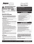
3.1 Interlock Installation
The Interlock provides module-to-module frame bonding through the interface with the Zep
Groove. The Interlock is UL Listed to UL 2703.
Alignment marks along the top edge of the Interlock aid in module positioning and tightening of
the fasteners.
Figure 3.1 Interlock Alignment Marks
Key side
Interlock
Zep
Used to align module edges
around center point
Farthest allowable position
to align with module edge
when shifting Interlock
Timing mark for Zep
Tool
Part No. 850-1388
Center point
Tongue side
© 2014/EN. Yingli Green Energy Holding Co., Ltd. reserves the right to make specifications changes without prior notice.
YINGLISOLAR.COM/US
File Generated April 9, 2014
Based on Zep Solar Document #800-1444-001 Rev F
Page 11
YGE-Z 60 CEL L SERI ES PV M O DULES INSTAL LA TION S UPP LEMENT
The Interlock is used to connect modules together.
Figure 3.2 Interlock Insertion
When modules are connected together using the
Interlock, there must be a 1/2” (12.7mm) gap between
modules
During installation of the Interlock, the Key side is
inserted into the Zep Groove with a downward sweeping
motion.
After the Interlock is inserted into the Zep Groove, the fasteners on the Interlock (the Interlock
Zeps) are rotated to provide East-West module bonding.
Figure 3.3 Interlock Key Side Installation Uses Zep Tool
Open
Closed
Key side of Interlock is manually
inserted into Zep Groove
The fasteners on the Interlock (the
“Interlock Zeps”) are tightened onequarter turn to lock securely into the
Zep Groove.
Rotation seen from Key side
© 2014/EN. Yingli Green Energy Holding Co., Ltd. reserves the right to make specifications changes without prior notice.
YINGLISOLAR.COM/US
File Generated April 9, 2014
Based on Zep Solar Document #800-1444-001 Rev F
Page 12
YGE-Z 60 CEL L SERI ES PV M O DULES INSTAL LA TION S UPP LEMENT
Alignment marks on the Interlock and the Zep Tool indicate exactly how far to rotate the Interlock
Zeps to secure the Key side. Installers should not over-tighten or under-tighten.
Figure 3.4 Zep Tool Rotation Positions
The Zep Tool is rotated from Position 1 to Position 3.
Position 1 - Open
Position 3 - Closed
When the Interlock Zeps are rotated to the closed position (Position 3), they are also in the correct
position to receive a module drop-in on the Tongue side. The difference between positions is easily
visible.
Figure 3.5 Interlock Zeps Showing Open and Closed Position
Position 1 - Open
Position 3 - Closed
© 2014/EN. Yingli Green Energy Holding Co., Ltd. reserves the right to make specifications changes without prior notice.
YINGLISOLAR.COM/US
File Generated April 9, 2014
Based on Zep Solar Document #800-1444-001 Rev F
Page 13
YGE-Z 60 CEL L SERI ES PV M O DULES INSTAL LA TION S UPP LEMENT
After the Interlock Zeps are secured on the Key side, the next row of modules is dropped-in on the
Tongue side to provide North-South bonding within the array.
Figure 3.6 Module Drop-In on Interlock Tongue Side 1
Frame of South module
installed on Key side of
Interlock Zep
Key side of Interlock
Zep within Interlock
product
Tongue side of
Interlock Zep within
Interlock product
Frame of North module
being positioned for
installation on the Tongue
side of the Interlock Zep
1
Bonding locations on Key side of
Interlock Zep
UL 2703 Listed Interlock product
© 2014/EN. Yingli Green Energy Holding Co., Ltd. reserves the right to make specifications changes without prior notice.
YINGLISOLAR.COM/US
File Generated April 9, 2014
Based on Zep Solar Document #800-1444-001 Rev F
Page 14
YGE-Z 60 CEL L SERI ES PV M O DULES INSTAL LA TION S UPP LEMENT
Figure 3.7 Module Drop-In on Interlock Tongue Side 2
Frame of North module being
dropped in on Tongue side of
Interlock Zep
2
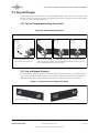
Figure 3.8 Module Drop-In on Interlock Tongue Side 3
Frame of North module being
dropped in on Tongue side of
Interlock Zep
3
Forced interference between
mating parts removes
anodization on module frame
© 2014/EN. Yingli Green Energy Holding Co., Ltd. reserves the right to make specifications changes without prior notice.
YINGLISOLAR.COM/US
File Generated April 9, 2014
Based on Zep Solar Document #800-1444-001 Rev F
Page 15
YGE-Z 60 CEL L SERI ES PV M O DULES INSTAL LA TION S UPP LEMENT
Figure 3.9 Module Drop-In on Interlock Tongue Side 4
Frame of North module in final
installation position
4
Forced interference between mating
parts removes anodization on module
frame, resulting in robust and UL
certified bonding path
© 2014/EN. Yingli Green Energy Holding Co., Ltd. reserves the right to make specifications changes without prior notice.
YINGLISOLAR.COM/US
File Generated April 9, 2014
Based on Zep Solar Document #800-1444-001 Rev F
Page 16
YGE-Z 60 CEL L SERI ES PV M O DULES INSTAL LA TION S UPP LEMENT
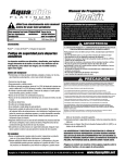
3.2 Ground Zep Installation
The Ground Zep is used to provide a path to ground for a Zep Compatible array. The Ground Zep is
UL Listed to UL 467 and UL 2703.
Figure 3.10 Ground Zep Installation
1
Insert a Ground Zep Into Module
i
ii
iii
Set screw
Ground wire
retention slot
Insert a Ground Zep in the Zep Groove of
any module around the array perimeter.
Start with the set screw at 9 o’clock position (pointing left).
Using either the Zep Tool or the Flat Tool (shown), lock
the Ground Zep into place by turning 1/4 turn clockwise.
After the Ground Zep is turned 90 degrees, the set screw
should be pointing straight up.
This locks the Ground Zep into the Zep Groove and
creates a solid ground bond with the module frame.
2
Connect Ground Zep to Building Ground/Earth.
Insert solid copper ground wire into the ground wire
retention slot and turn the set screw wtih a flat-bladed
screwdriver until the ground wire is captured by the set
screw. To fully secure, torque the set screw as follows:
• 14-10 AWG: 40 inch-lbs
• 8 AWG:
45 inch-lbs
• 6 AWG:
50 inch-lbs
© 2014/EN. Yingli Green Energy Holding Co., Ltd. reserves the right to make specifications changes without prior notice.
YINGLISOLAR.COM/US
File Generated April 9, 2014
Based on Zep Solar Document #800-1444-001 Rev F
Page 17
YGE-Z 60 CEL L SERI ES PV M O DULES INSTAL LA TION S UPP LEMENT
3.3 Cam Foot Installation
The Cam Foot is used to connect Zep Compatible modules to a Zep Compatible roof attachment
system. For ZS Span, the Cam Foot connects modules to Zep Solar Spanner Bars.
Figure 3.11 Cam Foot
Key Side
Tongue Side
Rockit
Cam Nut
© 2014/EN. Yingli Green Energy Holding Co., Ltd. reserves the right to make specifications changes without prior notice.
YINGLISOLAR.COM/US
File Generated April 9, 2014
Based on Zep Solar Document #800-1444-001 Rev F
Page 18
YGE-Z 60 CEL L SERI ES PV M O DULES INSTAL LA TION S UPP LEMENT
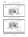
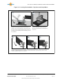
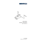
Figure 3.12 Cam Foot Installation - Zep Groove and Spanner Bar
i
ii
Install the Cam Foot into the rear edge of
a module row by inserting the Key side
into the Zep Groove. Use a sweeping
downward force to rotate the Cam Foot
until the Cam Nut is positioned within the
Spanner Bar channel.
iiia
Use the Flat Tool to rotate the Cam Nut 100
degrees clockwise to lock the Cam Nut into the
Spanner Bar.
iiib
iiic
Install the next row of modules by dropping the module onto the Tongue side of the Cam Foot
Rockit to engage the Zep Groove. Pivot the module downwards so that the top surface of the
module is parallel with the roof surface.
© 2014/EN. Yingli Green Energy Holding Co., Ltd. reserves the right to make specifications changes without prior notice.
YINGLISOLAR.COM/US
File Generated April 9, 2014
Based on Zep Solar Document #800-1444-001 Rev F
Page 19
YGE-Z 60 CEL L SERI ES PV M O DULES INSTAL LA TION S UPP LEMENT
3.4 Leveling Foot Installation
The Leveling Foot is used to connect Zep Compatible modules to a Zep Compatible roof attachment system. For ZS Comp, the Leveling Foot connects modules to Zep Solar Comp Mounts or Zep
Solar-approved standoffs.
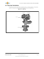
Figure 3.13 Cam Foot
Key Side
Tongue Side
Rockit
Leveling Foot
base
© 2014/EN. Yingli Green Energy Holding Co., Ltd. reserves the right to make specifications changes without prior notice.
YINGLISOLAR.COM/US
File Generated April 9, 2014
Based on Zep Solar Document #800-1444-001 Rev F
Page 20
YGE-Z 60 CEL L SERI ES PV M O DULES INSTAL LA TION S UPP LEMENT
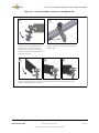
Figure 3.14 Leveling Foot Installation - Zep Groove and Comp Mount
i
ii
Install the Leveling Foot into the rear edge of a
module row by inserting the Key side into the Zep
Groove, using a sweeping downward force. Base of
Leveling Foot should be positioned directly over the
Comp Mount.
iiia
Secure Leveling Foot base to Comp
Mount using hardware provided by Zep
Solar, Inc.
iiib
iiic
Install the next row of modules by dropping the module onto the Tongue side of the Leveling Foot
Rockit to engage the Zep Groove. Pivot the module downwards so that the top surface of the
module is parallel with the roof surface.
© 2014/EN. Yingli Green Energy Holding Co., Ltd. reserves the right to make specifications changes without prior notice.
YINGLISOLAR.COM/US
File Generated April 9, 2014
Based on Zep Solar Document #800-1444-001 Rev F
Page 21
YGE-Z 60 CEL L SERI ES PV M O DULES INSTAL LA TION S UPP LEMENT
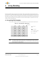
4
Array Bonding
The Zep Compatible design concept allows the installer to build a hyper-bonded array with a single ground
bond connection. In a hyper-bonded array, every module is structurally and electrically bonded to the surrounding modules, on all sides. The rotation of the Key side into the Zep Groove, and the dropping in of the next row of
PV modules onto the Tongue side, acts to establish a bond for all UL listed components by cutting through the
surface coating on the Zep Groove. This eliminates the need for extensive lengths of copper wire run to every
module in order to ground the array.
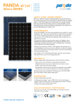
4.1 Grounding Path Examples
The following examples show how a Zep Compatible PV array is hyper-bonded using Interlocks.
Figure 4.1 Grounding Path - Simple Array
Interlock
Ground Zep
Equipment Grounding
Conductor (EGC)
Bond path
NOTE:
If an array contains Hybrid Interlocks or Thermal Expansion Joints, an additional Ground Zep may be required. Please refer directly to the Zep Solar installation manuals for further details.
© 2014/EN. Yingli Green Energy Holding Co., Ltd. reserves the right to make specifications changes without prior notice.
YINGLISOLAR.COM/US
File Generated April 9, 2014
Based on Zep Solar Document #800-1444-001 Rev F
Page 22
YGE-Z 60 CEL L SERI ES PV M O DULES INSTAL LA TION S UPP LEMENT
© 2014/EN. Yingli Green Energy Holding Co., Ltd. reserves the right to make specifications changes without prior notice.
YINGLISOLAR.COM/US
File Generated April 9, 2014
Based on Zep Solar Document #800-1444-001 Rev F
Page 23
Yingli Green Energy Americas, Inc.
YINGLISOLAR.COM/US
Tel: +1 (888) 686-8820