1
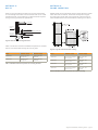
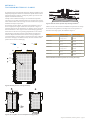
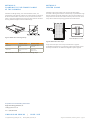
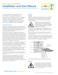
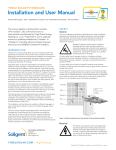
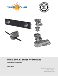
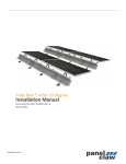
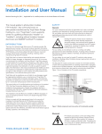
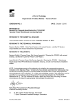
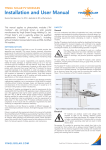
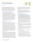
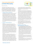
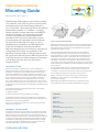
YINGLI SOLAR PV MODULES
Mounting Guide
Revision Date: March 1, 2014 | Version 1.0.
This Mounting Guide applies to photovoltaic modules
(“PV modules”, also commonly known as solar panels)
manufactured by Yingli Green Energy Holding Co.,
Ltd. (“Yingli Solar”) and is explicitly written for qualified
professionals (“Installer” or “Installers”), including
without limitation licensed electricians and NABCEPCertified PV Installers. This document is intended
to serve as a supplement to the Installation and
User Manual for Yingli Solar PV Modules, however
all requirements in the Installation and User Manual
for Yingli Solar PV Modules also apply. In case of
discrepancies, the Installation and User Manual for
Yingli Solar PV Modules shall take precedence.
Due to the development and continuous improvement
of Yingli Solar PV modules, the guidelines in this
Mounting Guide are subject to change without notice.
No rights can be derived from the Mounting Guide and
Yingli Solar assumes no liability whatsoever connected
to or resulting from the use of any information
contained herein.
INTRODUCTION
Specific site conditions or applications can make it challenging to
safely and effectively mount PV modules using conventional methods.
Fortunately, a growing number of hardware vendors and mounting
methods are available to the Installer to address these obstacles. The
intent of this document to is to present and discuss the comprehensive
range of approved options for mounting Yingli Solar PV modules, in
order to simplify and facilitate the installation process. At the same
time, it is also designed to give you clear instructions on how to attach
Yingli Solar PV modules to a given mounting structure in order to ensure
compliance with the requirements of the Yingli Solar Limited Warranty for
PV Modules.
Downward Load
(Wind & Snow)
Upward Load
(Wind)
Figure 1: Upward and downward loads
Mounting structures and other mechanical parts must be designed and
approved by a certified engineer for mounting PV modules and able to
withstand the design wind and snow loads applicable for a particular
geographical PV system location.
Unless otherwise specifically stated by Yingli Solar, the installation
instructions provided by the mounting structure manufacturer must
be strictly adhered to in order for the Yingli Solar Limited Warranty for
PV Modules to remain valid. In cases where the mounting structure
manufacturer either does not allow a particular configuration which is
permissible in accordance with this guide, or does not allow wind or
snow loads as high as what is specified by this guide, then the limitations
of that manufacturer’s installation instructions shall take precedence over
these guidelines.
During installation and operation, Yingli Solar PV modules must not
be subjected to forces from the mounting surface and substructure,
including but not limited to those forces caused by thermal expansion.
Do not modify the existing mounting holes or drill new holes.
Always consult with the local authority having jurisdiction before
installation in order to determine if any additional regulations or
requirements may apply.
Additionally, if your design load requirement is greater than those
shown, please contact your Yingli sales representative for options.
This guideline applies to the following product lines of PV modules
manufactured by Yingli Solar:
• YGE 60 Cell Series
• YGE 72 Cell Series (including the YGE-U 72 Cell Series)
CONTENTS
For additional information about the specifications of Yingli Solar PV
modules and installation requirements, please read the Installation and
User Manual for Yingli Solar PV Modules.
Method A:
B o l t s.. . . . . . . . . . . . . . . . . . . . . . . . . . . . . . . . . . . . . . . . . . . . . . . . . . . . . . . . . . . . . . . . . . 2
Thank you for choosing Yingli Solar as your PV module provider. We
appreciate your business!
GENERAL GUIDELINES
Yingli Solar PV modules can be mounted in one of several permissible
configurations, which are described in detail throughout this document.
Each configuration has a combined wind and snow load for both the
positive and negative directions that is maximally allowed by Yingli Solar
in order for the Yingli Solar Limited Warranty for PV Modules to remain
valid. Maximum design loads must be calculated according to ASCE
7-05: Minimum Design Loads for Buildings and Other Structures and
should be approved by a licensed structural engineer.
YINGLISOLAR.COM
Method B:
Frame Insertion.................................................... 2
Method C:
To p - d o w n / B o t t o m - U p C l a m p s . . . . . . . . . . . . . . . . . . . . . . . . . . . . . . . . . . 3
Method D:
Clamping to the Frame Flange
a t t h e C o r n e r s .. . . . . . . . . . . . . . . . . . . . . . . . . . . . . . . . . . . . . . . . . . . . . . . . . . . . . 4
Method E:
Center Clamp ...................................................... 4
Yingli Solar PV Modules, Mounting Guide / page 1
METHOD A:
B O LT S
METHOD B:
FRAME INSERTION
When mounting PV modules with bolts, the mounting holes located
on the rear flange of the frame must be used. Use either ¼ inch or M6
stainless steel bolts, nuts and washers. The bolts should be torqued to
racking/mounting manufacturer’s specifications.
Module frames can be supported by insertion systems where the module
frame rests inside of a channel. The channels are required to support
the entire length of either both of the long frames or both of the short
frames. Module frames must be restricted from vibrating in the channel.
PV Laminate
Aluminum
Frame
Backing Nut
Toothed Lock Washer or KEPS Nut
Equipment
Grounding
Conductor
Grounding Lug
Screw
Figure 2: Detail of a bolt mounting attachment
Table 1 includes a list of maximum allowable load pressure for modules
that are mounted with bolts through the mounting holes.
Figure 3: Long side and inside insertion mounting
Series
Attachment Location
Maximum Load (Pa)
Series
Attachment Location
Maximum Load (Pa)
YGE 60 Cell
4 bolts at each of the
mounting holes
2400 upward, 2400
downward
YGE 60 Cell
Two channels that support
both long frames
2400 upward, 2400
downward
YGE 72 Cell
4 bolts at the outer
mounting holes
2400 upward, 2400
downward
YGE 60 Cell
Two channels that support
both short frames
1900 upward, 1900
downward
YGE 72 Cell
Two channels that support
both long frames
2400 upward, 2400
downward
YGE 72 Cell
Two channels that support
both short frames
1900 upward, 1900
downward
Table 1: Allowable maximum load pressure for mounting with bolts
Table 2: Allowable maximum load pressure for insertion mounting
Yingli Solar PV Modules, Mounting Guide / page 2
METHOD C:
TOP-DOWN/BOTTOM-UP CLAMPS
PV modules may be mounted with third-party clamps provided they are
adequately designed to attach PV modules to a specific substructure for
site specific loading conditions. A clamp may attach up to two or more
adjacent modules simultaneously.
Clamps must be installed according to the manufacturer’s specified
instructions. Do not apply excessive pressure on the frame such that the
frame deforms. Refer to the mounting structure manufacturer for specific
hardware and torque requirements.
For clamping with four clamps, one clamp must be located in each of
the four regions (each region consists of 3 zones) shown in Figure 4.
Clamping locations may be distributed in an arbitrary manner as long as
there is attachment in each region and the overall clamping geometry
has at least one axis of mirror symmetry perpendicular to one module
side (see Figure 5). Highest maximum load pressures are approved
when the clamps are situated at each of the mounting holes plus or
minus 50mm (about 2 inches). Note: if symmetrical mounting is followed
but there is clamping in two different zones, the lower maximum load
pressure of the two zones shall apply.
ZONE
1
ZONE
2
ZONE
3
Figure 6: Detail of a center top-down clamp mounting attachment.
Table 3 includes a list of maximum allowable load pressures for clamps
at various mounting locations, including at the mounting holes or in
alternative mounting regions, as illustrated in Figure 4.
Three Mounting Zones
Series
Attachment Location
Maximum Load (Pa)
YGE 60 Cell
4 clamps at standard
mounting (Zone 1)
2400 Pa upward, 2400 Pa
downward
YGE 60 Cell
4 clamps at inside mounting
(Zone 2)
1900 Pa upward, 1900 Pa
downward
YGE 60 Cell
4 clamps at corner mounting
(Zone 3)
1520 Pa upward, 1520 Pa
downward
YGE 72 Cell
4 clamps at standard
mounting (Zone 1)
2400 Pa upward, 2400 Pa
downward
YGE 72 Cell
4 clamps at inside mounting
(Zone 2)
1900 Pa upward, 1900 Pa
downward
YGE 72 Cell
4 clamps at corner mounting
(Zone 3)
960 Pa upward, 960 Pa
downward
250mm
3
Zone 1 border
to module edge
1
100mm
2
150mm
Table 3: Allowable maximum load pressure for mounting with clamps
(+/-50mm from
mounting hole)
Figure 4: Mounting zones for mounting with clamps
Figure 5: One acceptable and one unacceptable mounting geometry
Yingli Solar PV Modules, Mounting Guide / page 3
METHOD D:
CLAMPING TO THE FRAME FLANGE
AT T H E C O R N E R S
Attachment of flange clamps, such as the Panelclaw “Claw”, are
permitted for Yingli Solar PV modules. The clamp attaches to the flange
of the PV module at each of the four corners, on either the two short
frame or long frame members. Ensure that the claws are flush with both
the long and short lengths of the PV module flange.
METHOD E:
CENTER CLAMP
Attachment with center clamps, such as the Array Technologies
DuraTrack™ HZ single axis tracker universal clamp, is permitted for Yingli
Solar PV modules. For proper attachment, place two PV modules into a
clamp so that the center of the module is lined up with the center of the
clamp. Ensure that the clamp fully grips both PV module frames.
Figure 7: Module with corner flange clamps
Center Clamp Cross Section
Figure 8: Module with center clamps
Series
Three Mounting
Zones
Attachment
Location
Maximum Load (Pa)
YGE 60 Cell
Flange of frame at four
corners
1520 upward, 1520
downward
YGE 72 Cell
Flange of frame at four
corners
960 upward,
960 downward
Yingli works with major center clamp manufacturers to approve
Three
Zones
acceptable load pressures
on Mounting
a project-by-project
basis. Please contact
the clamp manufacturer for details with regards to specific projects.
Table 4: Allowable maximum load pressure for corner flange clamps
For questions or more information, please contact:
Yingli Green Energy Americas, Inc.
[email protected]
Tel: +1 (888) 686-8820
YINGLISOLAR.COM/US
© Yingli Green Energy Holding Co. Ltd. |
|
NYSE: YGE
MountingGuide_US_201403_v01
Yingli Solar PV Modules, Mounting Guide / page 4