1
DESIGNED AND
MANUFACTURED
IN ENGLAND
WIND
SYSTEM
TABLE OF CONTENTS
PAGE
INTRODUCTION
2
PRE-TEST OF INSTRUMENT
2
INSTALLING THE MASTHEAD SENSOR UNIT
2
INSTALLING THE DISPLAY
2
NORMAL OPERATION
4
CHANGING THE BACKLIGHT SElTlNG
4
CHANGING THE POINTER SIZE
5
CHANGING THE POINTER STYLE
5
CHANGING THE SPEED SETTING
6
ENGINEERING
6
FAST AND AVERAGED SPEED DISPLAY
6
CHANGING BETWEEN FAST AND AVERAGED
SPEED DISPLAY
6
WIND VANE DEAD-AHEAD ALIGNMENT
7
SETTING DEAD-AHEAD WITH THE VANE ALIGNED
WITH THE VESSEL
8
SETTlNG DEAD-AHEAD BY TACKING THE VESSEL
8
EXAMPLE OF SETTING DEAD-AHEAD BY TACKING
9
REMOTE REPEATER FACILITY
12
1
INTRODUCTION
The Clipper Wind System is supplied complete with display unit,
mast head sensor unit, and mounting kit. It is designed to operate
from the vessel’s 12v battery supply.
PRE-TEST OF INSTRUMENT
Before mounting the units, check that the instrument is complete
and undamaged. Plug the masthead sensor unit into the display
unit and apply 12 volts. Gently spin the wind cups and the wind
vane and confirm the operation of the display.
INSTALLING THE MASTHEAD SENSOR UNIT
The masthead sensor unit is designed for mast mounting and is
supplied with 15 metres of cable. Choose a position where the
masthead unit can receive an unobstructed flow of air from all
directions. The masthead unit must be substantially horizontal,
however the orientation with respect to the vessel is unimportant.
Four mounting blocks together with four stainless steel self tapping
screws are supplied to screw the masthead unit to a metal mast. If
the masthead unit is to be fitted to a wooden mast, suitable screws
should be used.
After the masthead unit is securely fitted, run the cable to the
display unit and plug into the socket on the display. Do not reduce
any excess length of cable by cutting off the plug, but stow the
excess neatly. If the cable is not long enough, 5 metre and 15
metre extension cables are available.
INSTALLING THE DISPLAY
Select a convenient position for the display on a panel or bulk-head.
The site must be flat and the cavity behind the panel must remain
dry at all times. (The cable entry is deliberately not sealed to ensure
adequate ventilation. This prevents misting of the display).
2
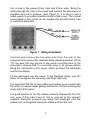
Cut a hole in the panel 67mm high and 87mm wide. Bring the
wiring through the hole in the panel and connect the black wire to
negative and red to positive. (See Figure 1). It is wise to use a
fused supply to provide protection should a fault occur. The current
consumption is very small, so any supply with at least a/amp fuse
is more than adequate.
-
Figure 1 Wiring Installation
Unscrew and remove the two wing nuts from the rear of the
instrument and remove the stainless steel clamping bracket. Fit the
“0” ring seal into the groove in the panel mounting face of the
instrument. Ensure that it is correctly lying in its groove before
fitting the instrument to the panel, which provides the watertight
seal for the display.
Fit the instrument into the panel, fit the stainless clamp over the
studs, fit and tighten the two wing nuts finger tight only.
It is important that the O-ring rubber seal makes good contact with
the panel to prevent water getting behind the unit and entering the
cavity behind the panel.
It is good practice to run the cables vertically downwards from the
unit, even if they later have to rise to connect to the vessel’s
supplies. Doing so prevents any water that might get onto the
cables from running back along the cables and into the unit.
3
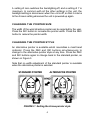
NORMAL OPERATION
When power is applied to the Clipper Wind system, it executes a
comprehensive internal test routine. It then displays the relative
wind direction and the wind speed. On a new unit, the relative wind
direction will not be correct until the dead-ahead setting is done.
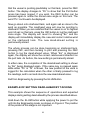
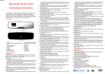
A typical display is shown on Figure 2.
Wind speed
6.3 knots
,
three-bar
wind pointer
-
Backlight
digit
Change / Chan 8' Decrease\ I n c r e h
Backlighting SPW!
number of pointer bars
scaling
Knots selected
-
Figure 2 Normal operation display.
CHANGING THE BACKLIGHT SETTING
Backlighting is provided to allow the unit to be seen at night. The
backlit area is restricted in the top corners of the display to
concentrate the lighting in the areas of interest (see Figure 2).
The brightness of the backlighting is adjusted by pressing the
ILLUM button at any time during normal operation. Each press of
the button increases the brightness by one in the range 0 to 7,
shown by the backlight indicator in the bottom left of the display
(see Figures).
4
,
A setting of zero switches the backlighting off, and a setting of 7 is
maximum. In common with all the other settings in the unit, the
backlight setting is stored even when the unit is off, so that it returns
to the chosen setting whenever the unit is powered up again.
CHANGING THE POINTER SIZE
The width of the wind direction pointer can be selected by the user.
Press the INC button to increase the pointer width. Press the DEC
button to reduce the pointer width.
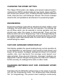
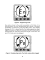
CHANGING THE POINTER STYLE
An alternative pointer is available which resembles a mast head
indicator. Press the DEC and INC buttons simultaneously to
change to the alternative pointer style at any time. Press the DEC
and INC buttons again to change back to the standard pointer, as
shown on Figure 3.
Note that no width adjustment of the standard pointer is available
when the alternative pointer is selected.
STANDARD POINTER
ALTERNATIVE POINTER
-
FIGURE 3 Setting the Arrow pointer style
5
CHANGING THE SPEED SETTING
The Clipper Wind system can display wind speed measurements in
miles per hour (MPH), nautical miles per hour (knots, shown as KTS),
and metres per second (m/s). Pressing SCALE switches between
knots, miles per hour, and metres per second. The choice is always
saved so the unit operates as set whenever it is powered up again.
ENGINEERING
Engineering settings means those adjustments which seldom need
changing, but which affect how the unit operates. The settings (as
are all those which can be selected in normal operation too) are
stored even when the power is disconnected. There are two
features which are set in Engineering - Fast or Averaged display of
the measured speed, and resetting the dead-ahead position so that
the display reads dead ahead when the wind vane is aligned foreand-aft along the vessel.
FAST AND AVERAGED SPEED DISPLAY
Fast display updates the speed reading during normal operation at
a rate dependent on wind speed: more quickly at high speed, and
slower at low speeds. Averaged readings are shown at a constant
update rate, and represent the average wind speed over
approximately three-second intervals. Averaged readings are
appropriate if speed changes during gusts are tiresome to observe,
but the accuracy of readings is the same in either mode.
CHANGING BETWEEN FAST AND AVERAGED SPEED
DISPLAY
Hold down the ILLUM button while turning on the power to put the
unit into the Engineering mode. The Engineering mode displays
“En” (for Engineering). The present vane reading is continuously
6
I
displayed. The wind speed is not displayed in Engineering mode,
but the speed display mode is shown on the backlight digit as "A"
for Averaged or "F" for fast .
Press the SCALE button to switch between Fast ("F" on the
backlight digit) and Averaged ( " A " ) speed display. The new setting
is stored for future operation. Pressing SCALE again switches
alternately between the two speed display modes.
Exit from Engineering by pressing the ILLUM button.
WIND VANE DEAD-AHEAD ALIGNMENT
It is always necessary to set the dead-ahead position of the vane
when it is first installed on the vessel so the display shows the
relative wind direction correctly. Setting the dead-ahead alignment
is very easy on the Clipper unit, and two methods are available.
The first requires access to the wind vane to physically align it
with the vessel’s fore-and-aft axis while setting the dead-ahead,
but the second can be done without access to the mast-head unit
during tacking.
In both methods, dead-ahead is realigned whenever the INC and
DEC buttons are pressed in turn when the unit is in Engineering
mode. It does not matter which button is pressed first: the
alignment is completed when the second of the two is pressed. The
new dead-ahead position is stored and the unit reverts to normal
Engineering mode.
The system automatically calculates the correct dead-ahead value
if it is set during tacking. The dead-ahead value is half-way
between equal angles to port and starboard. Equal angles to port
and starboard can be achieved by tacking as close as possible into
the wind on opposite tacks.
Both methods are described separately below, and an example of
doing the setting by tacking is also given.
7
SETTING DEAD-AHEAD WITH THE VANE ALIGNED
WITH THE VESSEL
Hold down the ILLUM button while applying the power to put the
unit into the Engineering mode. The Engineering mode displays
“En” (for Engineering). The present vane position is displayed, and
is unlikely to be correct on first installation.
Make sure the wind vane is correctly aligned with the vessel and
does not move during the setting process. Press the INC button,
whereupon the “En” display changes to “St” to show that the
Starboard button press has been logged. Now press the DEC
button to log the dead-ahead position and store the setting
permanently. The display will revert to showing “En” and the pointer
will move to indicate dead-ahead to show that the unit has correctly
stored the new value.
The same process can be done by pressing the DEC button first,
whereupon the display changes to “Po” to show that the Port
button press has been logged. Now press the INC button to log
the dead-ahead position and store the setting permanently. The
display will revert to showing “En and the pointer will move to
indicate dead-ahead to show that the unit has correctly stored the
new value.
Exit from Engineering by pressing the ILLUM button.
SETTING DEAD-AHEAD BY TACKING THE VESSEL
Hold down the ILLUM button while applying power to put the unit
into the Engineering mode. The Engineering mode displays “En”
(for Engineering). The present vane position is continuously
displayed, although its direction is unlikely to be correct on first
installation, and its position can be ignored during alignment.
Sail as close to the wind as possible on Port tack. (On this tack, the
masthead vane points to Port.) At a moment when you are satisfied
8
that the vessel is pointing predictably on that tack, press the DEC
button. The display changes to “Po” to show that the Port button
press has been logged. If you wish, the DEC button can be
pressed again to revise the stored vane angle on this tack. The
word “Po” continuesto be displayed.
Now go about onto starboard tack, and again sail as close to the
wind as possible. The masthead vane will now be pointing to
starboard. When you are satisfied that the vessel is on its highest
point of sail on this tack, press the INC button to log the starboard
vane angle. The display will revert to showing “En” and the
display will immediately display the new and correct relative wind
on the starboard tack. The new dead-ahead setting is
permanently stored.
The whole process can be done beginning on starboard tack,
pressing INC, and then tacking to port and pressing the DEC
button to log the dead-ahead value. When “En” is displayed
again, the display will show the correct relative wind direction on
the port tack. As before, the new setting is permanently stored.
In either case, the completion of the dead-ahead setting is shown
by “En” being displayed again. If the same key is pressed again
while either “Po” or “St” is shown, the new position of the vane is
logged for the calculation when the other is finally pressed to log
the readings, and to set and store the new dead-ahead value.
Exit from Engineering by pressing the ILLUM button.
EXAMPLE OF SETTING DEAD-AHEAD BY TACKING
This example shows the sequence of operations and expected
displays during setting dead-ahead by the process described above.
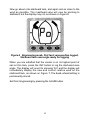
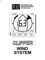
Hold down the ILLUM button while applying the power to put the
unit into the Engineering mode, as shown on Figure 4. The position
of the pointer at this stage is not important.
9
-
Figure 4 Engineering mode
Now sail as close to the wind as possible on Port tack. At a
moment when you are satisfied that the vessel is pointing
predictably on that tack, press the DEC button. The display
changes to “Po” to show that the Port button press has been
logged, as shown on Figure 5. If you wish, the DEC button can be
pressed again to revise the stored vane angle on this tack. The
word “Po” continues to be displayed.
-
Figure 5 Engineering mode, Port tack vane position logged
10
Now go about onto starboard tack, and again sail as close to the
wind as possible. The masthead vane will now be pointing to
starboard, but the display may not, as shown on Figure 6.
-
Figure 6 Engineering mode, Port tack vane position logged,
Starboard tack vane angle ready for logging
When you are satisfied that the vessel is on its highest point of
sail on this tack, press the INC button to log the starboard vane
angle. The display will revert to showing “En” and the display will
immediately display the new and correct relative wind on the
starboard tack, as shown on Figure 7.The dead-ahead setting is
permanently stored.
Exit from Engineering by pressing the ILLUM button.
11
-
Figure 7 Engineering mode, Dead-ahead logged, and
correctly showing starboard wind direction
REMOTE REPEATER FACILITY
A Repeating display unit and a Close-hauled & Running Display
unit are available for use with the Clipper Wind System. The
repeater cable is plugged into the rear of the master instrument.
The repeater socket on the master is exposed by pulling off the
round cover on the rear of the instrument. If no repeater is to be
connected, leave the cover in place.
If it is desired to use both a Repeating Display and a Close-hauled
& Running Display with a Clipper Wind System, the two additional
displays are connected one to the other in series. That is, one is
connected to the Master unit as a “slave” unit, and the other is
connected to the first “slave” unit as a further “slave”. All Clipper
Wind system units have this daisy-chain facility whereby as many
repeaters as desired may be connected to one master.
12