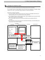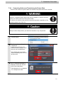
1
Machine Automation Controller NJ-series
General-purpose Serial
Connection Guide
(RS-232C)
OMRON Corporation
Ultra Small Multi-code Reader
(V400-R2 Series)
P567-E1-01
About Intellectual Property Rights and Trademarks
Microsoft product screen shots reprinted with permission from Microsoft Corporation.
Windows is a registered trademark of Microsoft Corporation in the USA and other countries.
EtherCAT® is registered trademark and patented technology, licensed by Beckhoff Automation
GmbH, Germany.
Sysmac is a trademark or registered trademark of OMRON Corporation in Japan and other
countries for OMRON factory automation products.
Company names and product names in this document are the trademarks or registered
trademarks of their respective companies.
Table of Contents
1.
Related Manuals ........................................................................................ 1
2.
Terms and Definitions ............................................................................... 2
3.
Remarks ..................................................................................................... 3
4.
Overview .................................................................................................... 5
5.
Applicable Devices and Device Configuration ....................................... 6
5.1.
Applicable Devices............................................................................. 6
5.2.
Device Configuration.......................................................................... 7
6.
Serial Communications Settings ............................................................. 9
6.1.
Serial Communications Settings ........................................................ 9
6.2.
Cable Wiring Diagram ...................................................................... 10
6.3.
Example of Connection Check......................................................... 12
7.
Connection Procedure ............................................................................ 13
7.1.
Work Flow ........................................................................................ 13
7.2.
Setting UP the Code Reader............................................................ 15
7.3.
Setting Up the Controller.................................................................. 16
7.4.
Checking the Serial Communications .............................................. 34
8.
Initialization Method ................................................................................ 40
8.1.
Initializing the Controller................................................................... 40
8.2.
Initializing the Code Reader ............................................................. 41
9.
Program.................................................................................................... 42
9.1.
Overview .......................................................................................... 42
9.2.
Communications sequence.............................................................. 46
9.3.
Error Detection Processing .............................................................. 47
9.4.
Variables .......................................................................................... 48
9.5.
ST Program...................................................................................... 51
9.6.
Protocol macro data ......................................................................... 56
9.7.
Timing Charts................................................................................... 63
9.8.
Error processing............................................................................... 64
10.
Revision History .................................................................................. 66
1. Related Manuals
1. Related Manuals
The table below lists the manuals related to this document.
To ensure system safety, make sure to always read and heed the information provided in all
Safety Precautions, Precautions for Safe Use, and Precaution for Correct Use of manuals for
each device which is used in the system.
Cat. No.
W500
Model
NJ501-[][][][]
Manual name
NJ-series CPU Unit Hardware User's Manual
NJ301-[][][][]
W501
NJ501-[][][][]
NJ-series CPU Unit Software User's Manual
NJ301-[][][][]
W494
CJ1W-SCU[]2
CJ-series Serial Communications Units
Operation Manual for NJ-series CPU Unit
W504
SYSMAC-SE2[][][]
Sysmac Studio Version 1 Operation Manual
W344
CXONE-AL[][]C-V4
CX-Protocol Operation Manual
/AL[][]D-V4
W502
NJ501-[][][][]
NJ-series Instructions Reference Manual
NJ301-[][][][]
Z333
V400-R2 Series
Ultra Small Multi-code Reader
V400-R2 Series User’s Manual
1
2. Terms and Definitions
2. Terms and Definitions
Term
Protocol macro
Explanation and Definition
A protocol macro is a function that stores a data send/receive procedure
(protocols) in a Serial Communications Board or Serial Communications
Unit to exchange data with general-purpose external devices by
executing the ExecPMCR instruction on the CPU Unit.
Protocol
A unit of independent communication processing with a specific
general-purpose device. A protocol includes a data send/receive
procedure. A protocol consists of multiple sequences.
Sequence
A unit of the independent communication processing which can be
started by executing the ExecPMCR instruction of a program. A
sequence that is started will execute steps registered in its own
sequence.
Step
A unit to execute any one of the followings: message send processing,
message receive processing, message send/receive processing, clear
receive buffer, or step wait. Up to 15 steps can be set per sequence.
Send message
A communication frame (command) sent to the external general-purpose
device. A send message is read from the step in the sequence, and sent
to the external general-purpose device.
Receive message
A communication frame (response) sent from the external
general-purpose device. A receive message is read from the step in the
sequence and is compared with data received from the general-purpose
external device.
Matrix
A matrix is used when a general-purpose external device sends multiple
types of communications frames (responses). More than one
communication frame can be registered in one matrix.
Case
A unit to register multiple communication frames (response) to a matrix.
One communication frame is registered as one case. Up to 15 types of
cases can be registered per matrix.
AT
This attribute allows the user to specify an address assigned to a
(AT specification)
variable. An I/O port or an address in memory used for CJ-series Units
can be specified.
2
3. Remarks
3. Remarks
(1) Understand the specifications of devices which are used in the system. Allow some
margin for ratings and performance. Provide safety measures, such as installing safety
circuit in order to ensure safety and minimize risks of abnormal occurrence.
(2) To ensure system safety, always read and heed the information provided in all Safety
Precautions, Precautions for Safe Use, and Precaution for Correct Use of manuals for
each device used in the system.
(3) The user is encouraged to confirm the standards and regulations that the system must
conform to.
(4) It is prohibited to copy, to reproduce, and to distribute a part or the whole of this document
without the permission of OMRON Corporation.
(5) The information contained in this document is current as of September 2013. It is subject
to change without notice for improvement.
3
3. Remarks
The following notation is used in this document.
Indicates a potentially hazardous situation which, if not avoided,
will result in minor or moderate injury, or may result in serious
injury or death. Additionally there may be significant property
damage.
Indicates a potentially hazardous situation which, if not avoided,
may result in minor or moderate injury or in property damage.
Precautions for Safe Use
Precautions on what to do and what not to do to ensure safe usage of the product.
Precautions for Correct Use
Precautions on what to do and what not to do to ensure proper operation and performance.
Additional Information
Additional information to read as required.
This information is provided to increase understanding or make operation easier.
Symbol
4
4. Overview
4. Overview
This document describes the procedure for connecting OMRON Corporation's Ultra Small
Multi-code Reader (V400-R2 series) (hereinafter referred to as the Code Reader) with
NJ-series Machine Automation Controller (hereinafter referred to as the Controller) via serial
communications, and describes the procedure for checking their connection.
Refer to the serial communications settings of the prepared Sysmac Studio project file and
understand the setting method and key points to connect the devices via serial
communications.
The user program in the Sysmac Studio project file and the protocol macro data in the
CX-Protocol project file are used to check the serial connection by executing the "Reading
Trigger" command on the Code Reader.
Prepare the latest Sysmac Studio project file and the CX-Protocol project file beforehand. To
obtain the files, contact your OMRON representative.
Name
Sysmac Studio project file
File name
Version
OMRON_V400-R2_PMCR232C_EV100.smc
Ver.1.00
OMRON_V400-R2_PMCR_EV100.psw
Ver.1.00
(extension: smc)
CX-Protocol project file
(extension: psw)
*Hereinafter, the Sysmac Studio project file is referred to as the "project file"
The user program in the project file is referred to as the "program"
The CX-Protocol project file is called the "Protocol macro data"
This document aims to explain the wiring method and communications settings
necessary to connect the corresponding devices and provide the setting
procedure. The program used in this document is designed to check if the
connection was properly established and is not designed to be constantly used at
a site. Therefore, functionality and performances are not sufficiently taken into
consideration. When you construct an actual system, please use the wiring
method, communications settings and setting procedure described in this
document as a reference and design a new program according to your application
needs.
5
5. Applicable Devices and Device Configuration
5. Applicable Devices and Device Configuration
5.1. Applicable Devices
The applicable devices are as follows:
Manufacturer
Name
OMRON
NJ-series CPU Unit
OMRON
OMRON
Serial Communications Unit
Ultra Small Multi-code Reader
Model
NJ501-[][][][]
NJ301-[][][][]
CJ1W-SCU[]2
V400-R2CF[][][]
Precautions for Correct Use
As applicable devices above, the devices with the models and versions listed in Section 5.2.
are actually used in this document to describe the procedure for connecting devices and
checking the connection.
You cannot use devices with versions lower than the versions listed in Section 5.2.
To use the above devices with versions not listed in Section 5.2 or versions higher than those
listed in Section 5.2, check the differences in the specifications by referring to the manuals
before operating the devices.
Additional Information
This document describes the procedure to establish the network connection. Except for the
connection procedure, it does not provide information on operation, installation or wiring
method. It also does not describe the functionality or operation of the devices. Refer to the
manuals or contact your OMRON representative.
6
5. Applicable Devices and Device Configuration
5.2. Device Configuration
The hardware components to reproduce the connection procedure of this document are as
follows:
Personal computer
(Sysmac Studio
installed,
OS: Windows 7)
Code Reader
V400-R2CF65
NJ501-1500
CJ1W-SCU42
Special cable (RS-232C)
V509-W011
USB cable
5 VDC power supply
Manufact
urer
OMRON
OMRON
OMRON
OMRON
OMRON
Serial Communications Unit
NJ-series CPU Unit
Power Supply Unit
Sysmac Studio
CX-Protocol
OMRON
Sysmac Studio project file
OMRON
CX-Protocol project file
-
Personal computer (OS: Windows7)
USB cable
(USB 2.0 type B connector)
Ultra Small Multi-code Reader
Special cable (RS-232C)
5 VDC power supply
OMRON
OMRON
-
Name
Model
CJ1W-SCU42
NJ501-1500
NJ-PA3001
SYSMAC-SE2[][][]
(Included in Sysmac
Studio.)
OMRON_V400-R2_PMC
R232C_EV100.smc
OMRON_V400-R2_PMC
R_EV100.psw
-
Version
Ver.2.0
Ver.1.05
Ver.1.06
Ver.1.97
Ver.1.00
Ver.1.00
V400-R2CF65
V509-W011
-
Precautions for Correct Use
Prepare the latest project file and protocol macro data in advance.
To obtain the files, contact your OMRON representative.
Precautions for Correct Use
Update the Sysmac Studio and CX-Protocol to the versions specified in this section or higher
versions using the auto update function. If a version not specified in this section is used, the
procedures described in Section 7 and subsequent sections may not be applicable. In that
case, use the equivalent procedures described in the Sysmac Studio Version 1 Operation
Manual (Cat. No. W504) and the CX-Protocol Operation Manual (Cat. No. W344).
7
5. Applicable Devices and Device Configuration
Additional Information
It may not be possible to reproduce the same operation with different devices or versions.
Check the configuration, model and version. If they are different from your configuration,
contact your OMRON representative.
Additional Information
For information on the special cable (V509-W011), refer to Cable for programmable controller
connection made by OMRON (V509-W011) in Specifications and External Dimension in
Section 5 Appendix of the Ultra Small Multi-code Reader V400-R2 Series User's Manual
(Cat. No. Z333).
Additional Information
The system configuration in this document uses USB for the connection to the Controller. For
information on how to install a USB driver, refer to A-1 Driver Installation for Direct USB Cable
Connection of the Sysmac Studio Version 1 Operation Manual (Cat. No. W504).
8
6. Serial Communications Settings
6. Serial Communications Settings
This section describes the specifications such as communication parameters and wiring that
are defined in this document.
Additional Information
To perform communications without using the settings described in this section, you need to
modify the program. For information on the program, refer to Section 9. Program.
6.1. Serial Communications Settings
The serial communications settings are shown below.
Setting item
Serial Communications Unit
Code Reader
Device name
J01
-
Unit number
0
-
Communications
Port 2 (RS-232C)
-
Serial communications mode
Protocol macro
-
Data length
8 bits
8 bits (Default)
Stop bit
1 bit
1 bit (Default)
Parity
None
None (Default)
Transmission rate (Baud rate)
9,600 bps (Default)
9,600 bps (Default)
Protocol macro transmissions
Full-duplex
-
Header
-
None (Default)
Footer
-
<CR> (Default)
Number of digit output
-
None (Default)
RS/CS control
-
None (no protocol system)
(connection) port
(Default)
CS waiting time
-
Not limited (Default)
ACK/NAK waiting time
-
Not limited (Default)
Precautions for Correct Use
This document describes the setting procedure of the CJ1W-SCU42 Serial Communications
Unit with unit number 0, communications (connection) port 2, and device name J01. To
connect devices under different conditions, change the variable names and setting values
used in the program by referring to 9. Program.
9
6. Serial Communications Settings
6.2. Cable Wiring Diagram
For details on the cable wiring, refer to Section 3 Installation and Wiring of the CJ-series Serial
Communications Units Operation Manual for NJ-series CPU Unit (Cat. No. W494).
Check the connector configuration and pin assignment before wiring.
You do not need to make a cable when you use the special cable (V509-W011).
■Connector configuration and pin assignment
<CJ1W-SCU42> Applicable connector: D-sub 9 pin
<V400-R2CF65> Applicable connector: DIN 8 pin
10
6. Serial Communications Settings
■Cable/Pin assignment
CJ1W-SCU42
Serial
Communications Unit
Ultra Small Multi-code Reader
(V400-R2CF65)
Signal
Pin No.
name
FG
1
SD
2
RD
3
RS-232C
RS
4
interface
CS
5
5V
6
DR
7
ER
8
SG
9
FG
Shell
D-SUB 9-pin
Cable connector type: Male
Pin No.
1
2
3
4
5
6
7
8
Signal
name
SD
RD
RS
CS
TRIG
NC
S.GND
VCC
RS-232C
interface
DIN 8-pin
Cable connector type: Female
External trigger
+5V
0V
*The external trigger is not used in this document. Insulate it from other cables.
*Connect +5V and 0V to the external power supply.
■Recommended parts for the connector
When you make a connection cable, use the following connectors to connect it to the
connector of the Code Reader.
Code Reader
V400-R2CF65
NJ501-1500
CJ1W-SCU42
Connection Cable
5 VDC
power
supply
■Special cable
The special cable (V509-W011) is used in this document.
Special cable (V509-W011)
NJ501-1500
CJ1W-SCU42
Code Reader
V400-R2CF65
*The external trigger is not used in this document. Insulate it from other cables.
*Connect +5V and 0V to the external power supply.
11
6. Serial Communications Settings
6.3. Example of Connection Check
This document shows an example of an ST (structured text) program and protocol macro data
in which the Controller sends/receives the message to/from the Code Reader.
The Controller and the Code Reader send and receive the message of "Reading Trigger
(sequence No. 900)". The following figure outlines the sequence operation.
●Overview of sequence operation
(1) The ST program executes the protocol macro instruction (ExecPMCR instruction) for
which sequence No. 900 of protocol macro data is specified
(2) The Reading Trigger command (sequence No. 900) is selected from the protocol macro
data, and it is sent to the Code Reader.
(3) The Code Reader executes the command according to the send data from the
Controller.
(4) The Controller receives the result of the command executed by the Code Reader, and
then stores in the specified variable.
Controller
CPU Unit
Project file
ST Program
Serial Communications Unit
RS-232C
Code Reader
Protocol macro
data
IF …. THEN
……….
ELSE
……….
END_IF;
Sequence No.1
Sequence No.2
ExecPMCR(….
Sequence No.900
(1) Executing the protocol
macro instruction
(Specifying sequence No.900)
(2) Reading Trigger
(Sequence No.900)
Send data
Receive data
(3) Executing the
command
Output_RecvData
Receive data
storage area
(4) Receiving the
execution result of
the command and
storing it in the
specified variable
12
7. Connection Procedure
7. Connection Procedure
This section describes the procedure for connecting the Code Reader to the Controller via
serial communications. This document explains the procedures for setting up the Controller
and the Code Reader from the factory default setting. For the initialization, refer to Section 8
Initialization Method.
7.1. Work Flow
Take the following steps to connect the Code Reader to the Controller via serial
communications.
7.2. Setting Up the Code Reader
↓
7.2.1. Cable Connection
↓
7.3. Setting Up the Controller
↓
7.3.1. Hardware Settings
↓
7.3.2. Starting the Sysmac Studio and
Importing the Project File
↓
7.3.3. Checking the Parameters and
Building
↓
7.3.4. Connecting Online and
Transferring the Project Data
↓
7.3.5. Transferring the Unit Settings
↓
7.3.6. Starting the CX-Protocol and
Opening the Protocol Macro
Data
↓
7.3.7. Connecting Online and
Transferring the Protocol Macro
Data
↓
7.4. Checking the Serial
Communications
↓
7.4.1. Starting the Trace
↓
7.4.2. Executing the Program
↓
Set up the Code Reader.
Connect a cable to the Code Reader.
Set up the Controller.
Set the hardware switches on the Serial
Communications Unit.
Start the Sysmac Studio and import the project file.
Check the parameters that are set, execute the
program check on the project data and build the
Controller.
Connect online with the Sysmac Studio and transfer
the project data to the Controller.
Transfer the setting data of the Serial
Communication Unit.
Start the CX-Protocol and open the protocol macro
data.
Connect online with the CX-Protocol, and transfer
the protocol macro data to the Serial
Communications Unit.
Execute the program and confirm that serial
communications are normally performed.
Start tracing with the CX-Protocol.
Execute the program with the Sysmac Studio.
13
7. Connection Procedure
7.4.3. Checking the Trace Data
↓
7.4.4. Checking the Receive Data
Confirm that the correct data is sent and received by
checking the trace data of the CX-Protocol.
Confirm that the correct data are written to the
variables of the Controller with the Sysmac Studio.
14
7. Connection Procedure
7.2. Setting UP the Code Reader
Set up the Code Reader.
7.2.1.
Cable Connection
Connect a cable to the Code Reader.
1
Connect the special cable
(V509-W011) to the Code
Reader.
Connect the 5 VDC power
supply to the special cable and
turn ON the power supply.
Code Reader
(V400-R2CF65)
Special cable
(V509-W011)
5 VDC power supply
Precautions for Correct Use
This document explains the procedures for setting up the Code Reader from the factory
default setting. If the Code Reader was changed from the factory default setting, make sure
to initialize by referring to Section 8.2. Initializing the Code Reader.
Additional Information
For details on the factory default setting of the Code Reader, refer to Factory default setting in
Return to the factory default setting in Menu Sheet/Command List in Section 4 Setting
Method of the Ultra Small Multi-code Reader V400-R2 Series User's Manual (Cat. No. Z333).
15
7. Connection Procedure
7.3. Setting Up the Controller
Set up the Controller.
7.3.1.
Hardware Settings
Set the hardware switches on the Serial Communications Unit.
Precautions for Correct Use
Make sure that the power supply is OFF when you perform the setting up.
1
Make sure that the power supply
to the PLC is OFF.
*If the power supply is turned
ON, settings may not be
applicable as described in the
following procedure.
Check the hardware switches
located on the front panel of the
Serial Communications Unit by
referring to the right figure
Check the connector for Port 2
(RS-232C) by referring to the
right figure.
*This setting is required to use
Port 2 of the Serial
Communications Unit.
2
Set the Unit No. Switch to 0.
(The unit number is set to 0 as
the factory default setting.)
3
Connect the Serial
Communications Unit to the
Controller as shown on the right.
Connect the special cable for
the Code Reader to the Serial
Communications Unit.
Connect the personal computer
to the Controller with a USB
cable.
Personal
computer
Controller
USB cable
Serial Communications Unit
End Cover
Code Reader
Power Supply Unit
Special cable
16
7. Connection Procedure
7.3.2.
Starting the Sysmac Studio and Importing the Project File
Start the Sysmac Studio and import the project file.
Install the Sysmac Studio and USB driver in the personal computer beforehand.
1
Confirm that the personal
computer and the Controller are
connected with the USB cable
and turn ON the power supply to
the Controller.
Start the Sysmac Studio. Click
the Import Button.
*If a confirmation dialog for an
access right is displayed at
start, select to start.
2
The Import File Dialog Box is
displayed. Select
OMRON_V400-R2_PMCR232C
_EV100.smc and click the
Open Button.
*Obtain the project file from
OMRON.
3
The
OMRON_V400-R2_PMCR232C
_EV100 project is displayed.
The left pane is called Multiview
Explorer, the right pane is called
Toolbox and the middle pane is
called Edit Pane.
*If an error message is displayed
stating "Failed to Load
Descendants", change the
version of the Sysmac Studio to
the version specified in 5.2.
Device Configuration or higher
version.
Multiview
Explorer
Edit Pane
Toolbox
17
7. Connection Procedure
7.3.3.
Checking the Parameters and Building
Check the parameters that are set, execute the program check on the project data and build
the Controller.
1
Double-click CPU/Expansion
Racks under Configurations
and Setup in the Multiview
Explorer.
2
The CPU/Expansion Racks Tab
is displayed in the Edit Pane.
Select the Serial
Communications Unit icon as
shown on the right.
Confirm that CJ1W-SCU42 is
displayed, the Device name is
J01, and the Unit No. is 0.
*If the settings are different,
change the values.
3
Click Edit Special Unit
Settings.
The 0 [Unit 0]: Tab is displayed.
Select Port2: Protocol macro
Settings from the pull-down list
of Parameter group to show.
18
7. Connection Procedure
4
Parameter group to show is set
to Port2: Protocol macro
Settings.
The setting items of the Port 2:
Protocol macro Settings are
shown.
Confirm that the Port2: Port
Settings is set to User settings
and other settings are the same
as those listed in Section 6.1.
*If the settings are different from
the above, change the values
from the pull-down lists. After
changing the values, click the
Apply Button.
5
Double-click I/O Map under
Configurations and Setup on
the Multiview Explorer.
The I/O Map Tab is displayed
and then the parameters for the
Unit are listed.
6
Confirm that data in the Variable
Columns start with J01 and the
Global Variable is set in each
Variable Type Column.
*If the settings are different from
the above, right-click on
CJ1W-SCU42 and select
Create Device Variable.
7
Double-click Task Settings
under Configurations and
Setup in the Multiview Explorer.
19
7. Connection Procedure
8
The Task Settings Tab is
displayed in the Edit Pane. Click
the Program Assignment
Settings Button and confirm
that Program0 is set under
PrimaryTask.
9
Select Check All Programs
from the Project Menu.
10
11
Confirm that "0 Errors" and "0
Warnings" are displayed in the
Build Tab Page under the Edit
Pane.
Select Rebuild Controller from
the Project Menu.
A confirmation dialog box is
displayed. Check the contents
and click the Yes Button.
A screen is displayed indicating
the conversion is being
performed.
12
Confirm that "0 Errors" and "0
Warnings" are displayed in the
Build Tab Page.
20
7. Connection Procedure
7.3.4.
Connecting Online and Transferring the Project Data
Connect online with the Sysmac Studio and transfer the project data to the Controller.
Always confirm safety at the destination node before you transfer a user
program, configuration data, setup data, device variables, or values in memory
used for CJ-series Units from the Sysmac Studio.
The devices or machines may perform unexpected operation regardless of the
operating mode of the CPU Unit.
Always confirm safety before you reset the Controller or any components.
1
Select Change Device from the
Controller Menu.
2
The Change Device Dialog Box
is displayed.
Confirm that the Device and
Version are set as shown on the
right and click the OK Button.
*If the settings are not correct,
select the setting items from the
pull-down list.
3
If the settings were changed in
step 2, the Build Dialog Box is
displayed. Check the contents
and click the Yes Button.
*This dialog box is not displayed
if no change was made.
21
7. Connection Procedure
4
Select Communications Setup
from the Controller Menu.
5
The Communications Setup
Dialog Box is displayed.
Select the Direct connection via
USB Option for Connection
Type.
Click the OK Button.
6
Select Online from the
Controller Menu.
*Example of confirmation dialog box
*If the dialog on the right is
displayed, the model or version
of the Controller does not
match that of the project file.
Review the Controller model,
version and device settings of
the project file, and then repeat
the procedure from step 1 in
this section. Close the dialog
box by clicking the OK Button.
*The model and version
displayed on the confirmation
dialog box differ depending on
the Controller used and the
device setting of the project file.
22
7. Connection Procedure
7
A confirmation dialog box is
displayed as shown on the right.
Check the contents and click the
Yes Button.
*The displayed dialog depends
on the status of the Controller
used. Check the contents and
click the Yes Button to proceed
with the processing.
*The displayed serial ID differs
depending on the device.
Additional Information
For details on online connections to a Controller, refer to Section 5 Online Connections to a
Controller of the Sysmac Studio Version 1 Operation Manual (Cat. No. W504).
8
9
When an online connection is
established, a yellow bar is
displayed on the top of the Edit
Pane.
Select Synchronization from
the Controller Menu.
23
7. Connection Procedure
10
The Synchronization Dialog Box
is displayed.
Confirm that the data to transfer
(NJ501 in the right dialog) is
selected. Then, click the
Transfer To Controller Button.
*After executing the Transfer To
Controller, the Sysmac Studio
project data is transferred to the
Controller and the data are
compared.
11
A confirmation dialog box is
displayed. Confirm that there is
no problem and click the Yes
Button.
A screen stating "Synchronizing"
is displayed.
A confirmation dialog box is
displayed. Confirm that there is
no problem and click the No
Button.
12
*Click the No Button to operate
in PROGRAM mode in the
following steps.
Confirm that the synchronized
data is displayed with the color
specified by "Synchronized",
and that a message is displayed
stating "The synchronization
process successfully finished"
If there is no problem, click the
Close Button.
*A message stating "The
synchronization process
successfully finished" is
displayed if the Sysmac Studio
project data if the data in the
Controller match.
*If the synchronization fails,
check the wiring and repeat the
procedure in this section.
24
7. Connection Procedure
13
Select Reset Controller from
the Controller Menu.
*When Mode is set to RUN
Mode, Reset Controller cannot
be selected. In this case, select
Mode - PROGRAM Mode from
the Controller Menu to change
to PROGRAM mode and
perform the procedure in this
step.
14
A confirmation dialog box is
displayed several times. Check
the contents and click the Yes
Button.
15
The Controller is reset and the
Sysmac Studio goes offline.
Then, the yellow bar on the top
of the Edit Pane disappears.
Go online again by following
steps 6 to 8.
25
7. Connection Procedure
7.3.5.
Transferring the Unit Settings
Transfer the setting data of the Serial Communication Unit.
1
Select Mode - PROGRAM
Mode from the Controller Menu.
2
A confirmation dialog box is
displayed. Confirm that there is
no problem and click the Yes
Button.
3
PROGRAM mode is displayed
on the Controller Status Pane.
4
Double-click CPU/Expansion
Racks under Configurations
and Setup in the Multiview
Explorer.
Select the Serial
Communications Unit icon.
Click Edit Special Unit
Settings.
The 0 [Unit 0]: Tab is displayed.
Click the Transfer To
Controller Button.
5
26
7. Connection Procedure
6
A confirmation dialog box is
displayed. Check the contents
and click the Yes Button.
A dialog box is displayed
indicating transferring is being
performed, and a confirmation
dialog box is displayed. Check
the contents and click the Yes
7
8
Button.
The Port Selection Dialog Box is
displayed.
Select All ports and click the OK
Button.
A confirmation dialog box is
displayed. Check the contents
and click the OK Button.
9
10
Select Port2: Protocol macro
Settings from the pull-down list
of Parameter group to show.
Click the Compare Button.
Confirm that "≠" (mismatch) is
not shown in the red frame on
the right.
27
7. Connection Procedure
7.3.6.
Starting the CX-Protocol and Opening the Protocol Macro Data
Start the CX-Protocol and open the protocol macro data.
1
Start the CX-Protocol.
Project Window
Project workspace
Output Tab Page
(CX-Protocol)
2
Select Open from the File Menu.
3
On the Open Dialog Box, select
OMRON_V400-R2_PMCR_EV1
00.psw and click the Open
Button.
*Obtain the protocol macro data
from OMRON.
4
The project workspace and the
Project Window display the
protocol macro data that was
read.
28
7. Connection Procedure
7.3.7.
Connecting Online and Transferring the Protocol Macro Data
Connect online with the CX-Protocol, and transfer the protocol macro data to the Serial
Communications Unit.
1
Double-click
OMRON_V400-R2_PMCR_EV1
00 on the project workspace to
display a tree.
2
Select Edit PC-PLC Comms
Settings from the PLC Menu.
3
The Change PLC Dialog Box is
displayed. Select a device type
to use from the pull-down list of
the Device Type, and click the
Settings Button.
*NJ501 is used in this
document.
4
The Device Type Settings
Dialog Box is displayed. Select
the CPU type to use from the
pull-down list, and click the OK
Button.
*1500 is used in this document.
29
7. Connection Procedure
5
Confirm that the Network Type is
set to USB on the Change PLC
Dialog Box and click the OK
Button.
*If the Network Type is not set to
USB, select USB from the
pull-down list.
6
Select Connect to PLC from the
PLC Menu.
7
The PLC icon on the project
workspace changes from Offline
to Program. It means that the
Controller is connected online.
8
*If Run is displayed, change it to
Program by following steps 8
and 9.
If the operating mode of the
Controller is Run, select
Operating Mode - Program
from the PLC Menu.
9
The dialog box on the right is
displayed. Confirm that there is
no problem and click the Yes
Button.
Confirm that the operating mode
was changed to Program mode
as shown in step 7.
10
Double-click the New Protocol
List on the project workspace to
display a tree.
30
7. Connection Procedure
11
The Project Window on the right
is displayed. Confirm that
SCU[0] is entered in the Target
Column.
*If SCU[0] is not entered, select
SCU[0] as shown on the right
figure.
12
Select New Protocol List and
select Download Protocols
from the Protocol Menu.
13
The dialog box on the right is
displayed. Select the Include
Source Information Check Box
and click the Compile Button.
14
When 100% is displayed in the
Complied % Column, the
compiling operation is
completed.
After confirming that the
compiling operation is
completed, click the Download
Button.
31
7. Connection Procedure
15
The dialog box on the right is
displayed. Confirm that there is
no problem and click the OK
Button.
16
Check that 100% is displayed in
the Downloaded % Column in
the right figure, and click the
Close Button.
17
Select New Protocol List and
select Compare Protocols from
the Protocol Menu.
18
The dialog box on the right is
displayed. Select the Include
Source Information Check Box
and click the Compile Button.
32
7. Connection Procedure
19
When 100% is displayed in the
Complied % Column, the
compiling operation is
completed.
Confirming that the compiling
operation is completed, and
click the Compare Button.
20
The dialog box on the right is
displayed. Confirm that
Successful is displayed in the
Result Column and click the OK
Button.
21
Confirm that 100% is displayed
in the Compared % Column in
the right figure, and click the
Close Button.
33
7. Connection Procedure
7.4. Checking the Serial Communications
Execute the program and confirm that serial communications are normally performed.
Sufficiently confirm safety before you change the values of variables on a Watch
Tab Page when the Sysmac Studio is online with the CPU Unit. Incorrect
operation may cause the devices that are connected to Output Units to operate
regardless of the operating mode of the Controller.
Precautions for Correct Use
This document explains the procedures for setting up the Code Reader from the factory
default setting. If the Code Reader was changed from the factory default setting, make sure
to initialize by referring to Section 8.2. Initializing the Code Reader.
Precautions for Correct Use
Confirm that the serial cable is connected before proceeding to the following procedure.
If it is not connected, turn OFF the power supply to each device, and then connect the serial
cable.
7.4.1.
Starting Tracing
Start tracing with the CX-Protocol.
1
Select Operating Mode - Run
from the PLC Menu of the
CX-Protocol.
2
The dialog box on the right is
displayed. Confirm that there is
no problem and click the Yes
Button.
3
Confirm that the operating mode
was changed to the Run mode,
and double-click NewPLC1
.
34
7. Connection Procedure
4
5
6
7
The tree under NewPLC1
expands. Select the Serial
Communications Unit (SCU[0] is
selected in the right figure).
Select the Trace 2 Icon ( ) on
the Project Window.
Confirm that Trace 2 is
highlighted as shown in the right
figure.
*Trace 2 corresponds to port 2 of
the Serial Communications
Unit.
Select Start Trace - One Shot
Trace from the PLC Menu.
Confirm that the status of Trace
2 in the Project Window was
changed to One-shot Trace
Running.
35
7. Connection Procedure
7.4.2.
Executing the Program
Execute the program with the Sysmac Studio.
1
Select Watch Tab Page from
the View Menu of the Sysmac
Studio.
2
The Watch1 Tab Page is
displayed in the lower section of
the Edit Pane.
Confirm that the variables shown
on the right are displayed in the
Name Columns.
3
*To add a variable, click Input
Name.
is displayed to the left of
*If
the variable instead of
, click
and open the configuration
of the structure variable.
*Program0 of the Name is
omitted from the following
descriptions.
4
Start input
Program
execution status
Error codes
Receive data after
converted to a string
Receive data
storage area
Read the bar code shown on the
right as an example.
Position the Code Reader so that
it can read the bar code shown
on the right.
36
7. Connection Procedure
5
Click TRUE on the Modify
Column of Input_Start.
The online value of Input_Start
changes to True.
The program operates, serial
communications are performed
with the Code Reader, and then
the bar code is read.
*If Read confirmation LED that is
on the top of the Code Reader
is lit green and a buzzer
sounds, then the read operation
succeeds.
A buzzer sounds if the read operation succeeds.
*If the bar code shown in the
document cannot be read, read
a bar code shown in Preliminary
Examination in Section 2
Introduction Procedure of the
Ultra Small Multi-code Reader
V400-R2 Series User's Manual
(Cat. No. Z333). When reading,
change Input_Start to False and
then change Input_Start to True
again by using the same
procedure as this step.
37
7. Connection Procedure
7.4.3.
Checking the Trace Data
Confirm that the correct data is sent and received by checking the trace data of the
CX-Protocol.
1
Select Upload Trace from the
PLC Menu from the
CX-Protocol.
2
A dialog box on the right is
displayed. Check the contents
and click the Yes Button.
3
Check the send/receive
message on the trace data file
shown in the right figure.
*In the example on the right, the
Reading Trigger command is
sent from the Controller and the
bar code data that are shown in
step 4 of Section 7.4.2. are
received.
■ Send message
Hex
:1B 5A 0D
String :[ESC]”Z”[CR]
■ Receive message
Hex
:34 39 31 32 33 34 35 36 37 38 39 30 34 0D
String :“4912345678904”[CR]
38
7. Connection Procedure
7.4.4.
Checking the Receive Data
Confirm that the correct data are written to the variables of the Controller with the Sysmac
Studio.
1
Confirm that the online value of
Local_Status.Done, which
indicates the program execution
status, was changed to True.
[Normal end]
*This means the program ended
normally.
*In the case of an error end,
Local_Status.Error changes to
True. Troubleshoot the error by
referring to step 2.
2
If the program ended normally,
confirm that each error code is 0.
*If the program ended in an
error, the error code
corresponding to the error is
stored. Troubleshoot the error
by referring to 9.8. Error
Process.
3
[Error end]
[Normal end]
[Error end]
Check the received data (code
that was read) in the Watch
Window of the Sysmac Studio.
*In the example on the right, the
data stored in
Output_RecvMessage is
4912345678904. It is the same
as the trace data in step 3 of
Section 7.4.3.
*The number of words used to
store the receive data (0008 in
hexadecimal) is stored in
Output_RecvData[0]. The bar
code data that were read are
stored from
Output_RecvData[1] to [7]. The
number of used words is 8
including Output_RecvData[0].
Receive data (Hex)
• Output_RecvData[0]:”0008”
Number of words used to
store the receive data
Eight words from 0 to 7
• Output_RecvData[1]:“3439”
• Output_RecvData[2]:”3132”
• Output_RecvData[3]:”3334”
• Output_RecvData[4]:”3536”
• Output_RecvData[5]:”3738”
• Output_RecvData[6]:”3930”
• Output_RecvData[7]:”3400”
Values of Bar Code (String)
Output_RecvMessage
“4912345678904”
39
8. Initialization Method
8. Initialization Method
This document explains the setting procedure from the factory default setting.
Some settings may not be applicable as described in this document unless you use the
devices with the factory default setting.
8.1. Initializing the Controller
To initialize the Controller, it is necessary to initialize the Serial Communications Unit and the
CPU Unit. Place in PROGRAM Mode before the initialization.
8.1.1.
Serial Communications Unit
To initialize the settings of the Serial Communications Unit, click Edit Special Unit Settings of
CJ1W-SCU42 in CPU/Expansion Racks from the Sysmac Studio.
Click the Return to default Button and click the Apply Button. Then, click the Transfer To
Controller Button.
40
8. Initialization Method
8.1.2.
CPU Unit
To initialize the settings of the Controller, select Clear All Memory from the Controller Menu of
the Sysmac Studio. The Clear All Memory Dialog Box is displayed. Click the OK Button.
8.2. Initializing the Code Reader
For the initialization of the Code Reader, refer to Return to the factory default setting in Menu
Sheet/Command List in Section 4 Setting Method of the Ultra Small Multi-code Reader
V400-R2 Series User's Manual (Cat. No. Z333).
41
9. Program
9. Program
This section describes the details on the program and the protocol macro data used in this
document.
9.1. Overview
This section explains the specifications and functions of the program and the protocol macro
data that are used to check the connection between the Code Reader (hereinafter referred to
as the destination device) and the Controller (Serial Communications Unit) (hereinafter
referred to as the Serial Communications Unit).
This program and protocol macro data use the protocol macro function of the Serial
Communications Unit to send/receive the Reading Trigger command to/from the destination
device and to detect whether the operation ends normally or ends in an error.
A normal end of this program means a normal end of the communications sequence of the
protocol macro.
An error end means an error end of the communications sequence of the protocol macro.
In this section, the prefix "10#" (possible to omit) is added to decimal data and the prefix "16#"
to hexadecimal data when it is necessary to distinguish between decimal and hexadecimal
data. (e.g., "1000" or "10#1000" for decimal data and "16#03E8" for hexadecimal data, etc.)
Also, to specify a specific data type, the prefix "<data type>#" is added. (e.g.,
"WORD#16#03E8")
Additional Information
OMRON has confirmed that normal communications can be performed using this program
and protocol macro data under the OMRON evaluation conditions including the test system
configuration, version and product lot number of each device which was used for evaluation.
OMRON does not guarantee the normal operation under the disturbance such as electrical
noise or the performance variation of the device.
42
9. Program
9.1.1.
Communications Data Flow
The following figure shows the data flow from when the Controller (Serial Communications
Unit) issues command data via serial communications to the destination device until when it
receives the response data from the destination device.
1.
Executing the
The CPU Unit executes the protocol macro instruction
communications sequence
(Instruction: ExecPMCR) with the sequence number
specified in the program, and loads the
communications sequence (protocol macro data)
registered in the Serial Communications Unit.
↓
2.
Sending a command
The Serial Communications Unit issues the send
message (command data) to the destination device
based on the sequence number specified in step 1.
↓
3.
Response receive
The Serial Communications Unit receives the message
processing
(response data) from the destination device, and stores
it in the specified internal memory of the CPU Unit.
43
9. Program
9.1.2. Function Block for Executing Protocol Macro and Send/Receive
Messages
This section describes the function block for executing the protocol macro (hereinafter
referred to as ExecPMCR instruction) and outlines the general operation of the send/receive
messages.
Additional Information
Refer to Serial Communications Instructions (ExecPMCR) in Section 2 Instruction
Descriptions of the NJ-series Instructions Reference Manual (Cat. No. W502) for details.
●ExecPMCR instruction
This program uses the following standard instruction to perform serial communications.
Name
Function blocks
Protocol macro
ExecPMCR
Explanation
Requests execution of a communications sequence (protocol
data) registered in a Serial Communications Unit.
●ExecPMCR instruction argument data
•Data type (_sPORT) of destination port Port
44
9. Program
●Send/Receive messages
[Overview of send/receive messages]
Send message
*
*
*
Controller
Receive message
*
*
*
*
Data
*
*
*
Destination
device
*
Terminator
*
*
*
*
*
Terminator
Data
[Relationship between the SrcDat[ ] send data array and the send message]
ScrDat[0]
Bit
CPU → Communications Unit
Send data array: ScrDat[ ]
15
*
*
ScrDat[1]
0 15
*
*
*
*
ScrDat[2]
0 15
*
*
*
*
ScrDat[n-1]
0 15
*
*
*
*
0
*
*
No. of send
data words
Communications Unit →
Destination Device
Send message
*
*
*
*
*
*
*
*
Terminator
Data
[Relationship between the DstDat[ ] receive data array and the receive message]
Destination device
→ Communications Unit
Receive message
*
*
*
*
*
*
*
*
Terminator
Data
No. of receive
data words
Bit 15
Communications Unit → CPU
Receive data array: DstDat[ ]
*
*
*
DstDat[0]
*
0 15
*
*
*
DstDat[1]
*
0 15
*
*
*
DstDat[2]
*
0 15
*
*
*
*
0
DstDat[n-1]
45
9. Program
9.2. Communications sequence
This section explains the communications sequence (protocol macro data) that can be used
for the ExecPMCR instruction of this program.
9.2.1.
Communications sequence No.
A communications sequence (protocol macro data) that is registered in the Serial
Communications Unit is identified by a communications sequence number. The Controller
executes the corresponding command on the destination device by specifying a
communications sequence number in the ExecPMCR instruction.
This protocol macro data includes the following communications sequence.
No.
Command name
900
Reading Trigger
9.2.2.
Description
Issues the reading trigger for a code.
ExecPMCR instruction input variables
The ExecPMCR instruction input variables for communication sequence No.900 Reading
Trigger are set as follows.
Variable
Port
UnitNo
PhysicPortNo
SeqNo
SrcDat[] (array)
DstDat[] (array)
Name (data format)
Destination port specification
(_sPROT)
Data (explanation)
-
_eUnitNo#_CBU_No00
(Specifies the unit number for the
Serial Communications Unit.)
USINT#10#2
Serial port number (USINT)
(Use serial port No.2.)
Communications
sequence UINT#10#900
number (UINT)
(Specifies Reading Trigger.)
WORD#16#0000
(The number of words of send data
Send data array (WORD)
is 0.: Specifies that no parameter
is required for the command.)
(Receive data. Setting is
Receive data array (WORD)
unnecessary)
Unit number (_eUnitNo)
46
9. Program
9.3. Error Detection Processing
This program detects and handles the errors (1) to (3) below. For information on error codes,
refer to 9.8 Error Process.
Controller
Destination device
Serial cable
(1) (2)
(3)
(1) Errors when executing the ExecPMCR instruction (ExecPMCR instruction error)
Errors occurred during an execution of the ExecPMCR instruction such as a unit error and
communications error are detected as ExecPMCR instruction errors. An error is detected
with the error code (ErrorID) and the expansion error code(ErrorIDEx) of the ExecPMCR
instruction.
(2) Errors at an execution of the protocol macro (protocol macro error)
When an operation ends in an error during an execution of a protocol macro for some
reason, it is detected as a protocol macro error. An error is detected with the Sequence
Abort Completion Flag (J01_P2_PmrSeqAbtSta).
(3) Errors in the destination device (Destination device errors)
Destination device errors include a command error, a parameter error, data error, and an
execution failure in the destination device. An error is detected with the response data
which is returned from the destination device. With this program, the destination device
does not send a response when an error occurs. Therefore, this error is detected as a
timeout error described in (2).
The causes of errors (1) and (2) may be related to each other. Therefore, all of the following
error codes are stored when either error occurs.
• Error code of ExecPMCR instruction (ErrorID)
• Expansion error code of ExecPMCR instruction (ErrorIDEx)
• Protocol macro error code (lower four bits of J01_P2_PmrSta)
• Transmission error status (J01_P2_TransErrSta)
47
9. Program
9.4. Variables
The variables used in this program are listed below.
9.4.1.
List of user-defined variables
The following tables list the data type, external variables (user-defined global variables/device
variable for CJ-series Unit/system-defined variable) and internal variables that are used in this
program.
●Data type (Structure)
[Communications processing status flags]
Name
sStatus
Data type
STRUCT
Busy
BOOL
Done
BOOL
Error
BOOL
Explanation
Structure of communications processing status flags
Communications processing in progress flag
TRUE: Processing is in progress. / FALSE: Processing is
not in progress
Communications processing normal end flag
TRUE: Normal end / FALSE: Other than normal end
Communications processing error end flag
TRUE: Error end / FALSE: Other than error end
●External variables
[User-defined global variables]
Variable name
Data type
Explanation
Communication start switch
The program starts when this flag changes from FALSE to
TRUE
Input_Start
BOOL
Input_SendData
ARRAY[0..249]
OF WORD
Send data storage area (500 bytes (WORD))
Output_RecvData
ARRAY[0..249]
OF WORD
Receive data storage area (500 bytes (WORD))
An area that stores DstDat[ ] of the ExecPMCR
instruction
Output_RecvMessage
STRING[498]
Output_PmrErrorID
WORD
Output_PmrErrorIDEx
DWORD
Output_PmrStaErrCode
WORD
Output_TransErrCode
WORD
AT
%5500
(*)
An area that stores the receive data after converted into a
string. (498 characters)
An area that stores an error code of the ExecPMCR
instruction
Normal end: 16#0000
An area that stores an expansion error code of the
ExecPMCR instruction
Normal end: 16#00000000
An area that stores a protocol macro error code
Normal end: 16#0000
An area that stores the transmission error status flag
Storage area of J01_P2_TransErrSta
Normal end: 16#0000
*You need to use an AT specification for the area that stores DstDat[ ] of the ExecPMCR instruction to specify
an address in the memory used for CJ-series Units.
48
9. Program
[Device variables for CJ-series Unit] (Serial Communications Unit)
Variable name
J01_P2_PmrExecSta
BOOL
Explanation
Protocol macro operation status
Bits 03 to 00: Protocol macro error code
Protocol Macro Execution Flag
J01_P2_PmrSeqEndSta
BOOL
Sequence End Completion Flag
J01_P2_PmrSeqAbtSta
BOOL
Sequence Abort Completion Flag
J01_P2_TransErrSta
WORD
Transmission error status
J01_P2_PmrSta
Data type
WORD
Additional Information
For details on the variables of the Serial Communications Unit, refer to 2-3 Device Variable
for CJ-series Unit in the CJ-series Serial Communications Units Operation Manual for
NJ-series CPU Unit (Cat.No. W494).
[System-defined variable]
Variable name
_Port_isAvailable
Data type
BOOL
Explanation
Communications Port Enabled Flag
TRUE: A port is available
FALSE: A port is not available
Additional Information
For information on the system-defined variables when the ExecPMCR instruction is used,
refer to Related System-defined Variables in Serial Communications Instructions
(ExecPMCR) in Section 2 Instruction Descriptions of the NJ-series Instructions Reference
Manual (Cat. No. W502).
●Internal variables (Instance variables)
The following tables list the internal variables used to execute the function blocks in the
program. An internal variable is called an "instance". The name of the function block to use
is specified as the data type of the variable.
Variable name
Data type
ExecPMCR_instance
ExecPMCR
F_TRIG_instance
F_TRIG
Explanation
Requests execution of a communications sequence
(protocol data) registered in a Serial Communications Unit.
Outputs TRUE for one task period only when the input
signal changes to FALSE.
Additional Information
For information on the ExecPMCR instruction, refer to Serial Communications Instructions
(ExecPMCR) in Section 2 Instruction Descriptions of the NJ-series Instructions Reference
Manual (Cat. No. W502).
Additional Information
For information on the F_TRIG instruction, refer to Sequence Input Instructions (F_TRIG) in Section 2
Instruction Descriptions of the NJ-series Instructions Reference Manual (Cat. No. W502).
49
9. Program
●Internal variables
Variable name
Data type
Local_Status
sStatus
Local_State
Local_ExecFlgs
Local_EndExecPMCR
Local_InPort
Local_SeqNo
Local_PmrStaCode
DINT
BOOL
BOOL
_sPort
UINT
WORD
ARRAY[0..248]
OF WORD
UINT
ARRAY[0..497]
OF BYTE
UINT
Local_RecvWordData
Local_RecvWordSize
Local_RecvByteData
Local_RecvByteSize
Explanation
Communications processing status flags
This variable is defined as sStatus structure
Status processing number
Communications instruction execution flag
Protocol macro execution end detection flag
Used port
Communications sequence number
Protocol macro error code edit area
An area that extracts and stores the data to be converted
into a string from the receive data (498 bytes)
A size of data to be converted into a string (unit: WORD)
An area that stores data in a byte array, which will be
converted into a string (498 bytes)
A size of data to be converted into a string (unit: BYTE)
50
9. Program
9.5. ST Program
9.5.1.
Functional Components of the Program
This program is written in the ST language. The functional components are as follows:
Major
classification
1.Communications
processing
2.Initialization
processing
3.PMCR
communications
processing
4.Processing
number error
process
Minor classification
1.1. Starting the communications
processing
1.2. Clearing the communications
processing status flags
1.3. Entering in the communications in
progress status and shifting to each
state processing
2.1. Initializing the communications
instruction
2.2. Initializing the communications
instruction execution flag
2.3. Initializing the error code storage areas
2.4. Setting the input variable of the
ExecPMCR instruction
2.5. Initializing the receive data storage
areas
2.6. Initialization setting end processing
3.1. Determining the communications
processing status and setting the
execution flag
3.2. Executing the communications
instruction
-
Description
The communications processing
starts.
The parameter setting of the
communications instruction
(ExecPMCR instruction) and the
receive data storage areas are
cleared.
The ExecPMCR instruction is
executed.
A normal end or an error end of the
execution is detected.
The error processing is executed
when a non-existent status
processing number is detected.
51
9. Program
9.5.2.
Program List
The program is shown below.
●Program: Program0 (General-purpose serial communications connection check program)
1.Communications processing
52
9. Program
2.Initialization processing
To change the input values such as the unit number of the Serial Communications Unit, the
port number to be used, protocol macro sequence number and send data size, change the
code indicated by a red frame.
53
9. Program
3.PMCR communications processing
54
9. Program
4.Processing number error process
55
9. Program
9.6. Protocol macro data
Protocol macro data consists of sequence, step, send/receive message, and matrix. Its
composition is described as follows.
●When there is only one receive message format for a step (send/receive once)
•Set one send message and one receive message for the step
Sequence No.900
Step No.00
Send message 00
Receive message 00
•
•
Step No.yy
Send message yy
Receive message yy
Sequence No. xxx
xxx: 999 max. yy: 15 max
●When there are several types of receive message formats for a step (send/receive once)
•Set the send message and matrix for the step
•Set several types of cases (receive messages) for the matrix
Sequence No.900
Step No.00
Send message 00
<Matrix>
Receive message
Case No.00
•
•
•
00
Step No.yy
Receive message
yy: 15 max
zz: 14 max
Case No.zz
zz
Sequence No. xxx
9.6.1.
xxx: 999 max
Case No.15 is automatically set
Case No.15
Other
Composition of Protocol Macro Data
In this protocol macro data, there is only 1 type of receive message (SD_RDCODE) for the
send message (SD_RDCODE). Therefore, the following composition is used without using the
matrix. Refer to 9.6.6. Receive Message Settings for details.
Sequence No.900
Step No.00
SD_RDCODE
RV_RDCODE
56
9. Program
9.6.2.
Protocol Macro Processing Procedure
This section describes the processing procedure of the protocol macro.
1.
[Step No.00]
Issuing send message (SD_RDCODE)
↓
2.
3.
When step No.00 ends normally
When step No.00 ends in an error
↓
↓
Next Process: Terminates the
Error Process: Interrupts the step as an
communications sequence as an
Abort and terminates the communications
End.
sequence.
↓
↓
(End)
(End)
57
9. Program
9.6.3.
Sequence Settings
This protocol macro data performs Reading Trigger (read code) by using communications
sequence No. 900. Set the timeout periods for the communications sequence.
Additional Information
Refer to 3-2 Sequence Attributes (Common to All Steps) of the CX-Protocol Operation
Manual (Cat. No. W344) for details on sequence settings.
●Timeout period setting
The following is the settings of the timeout periods (Timer Tr, Tfr, and Tfs) which are set for
the sequence.
[Communications sequence setting screen]
<Settings>
Item
Description
Timer
Tr
Receive wait
monitoring time
Timer
Tfr
Receive
finished
monitoring time
Timer
Tfs
Send finished
monitoring time
Explanation
Monitors the time from the receive wait status to the reception
of the first data (header) in the step of the sequence.
This timer is set to 3 seconds in this protocol macro data.
Monitors the time from the reception of the first data to the
completion of the reception in the step of the sequence.
This timer is set to 3 seconds in this protocol macro data.
Monitors the time from the sending of the header to the sending
of the last data.
This timer is set to 3 seconds in this protocol macro data.
Additional Information
Refer to Section 4-5 Calculation Method of Monitoring Time of the CX-Protocol Operation
Manual (Cat. No. W344) for the calculation method of monitoring time.
58
9. Program
9.6.4.
Step Settings
This section describes the step settings for communications sequence No. 900. The settings
include retry count, send/receive messages (message names), next process, and error
process. The sequence of this protocol macro data includes Step No.00 only.
Additional Information
Refer to 3-3 Step Attributes of the CX-Protocol Operation Manual (Cat. No. W344) for details
on step settings.
●Retry count setting
This section describes the retry count setting for the step. The step is retried for the
specified number of times (0 to 9 times) when an error occurs. If an error occurs after retries,
the step moves to the error process.
The retry count is enabled for the Send&Receive command only.
<Step setting screen>
<Settings>
Step No.
Retry count
00
3
●Send/Receive message (massage name) settings
This section describes the settings for the send/receive messages of the step. Here, a
registered send message name and message name are selected.
<Step setting screen>
<Settings>
Step No.
Send message
Receive message
00
SD_RDCODE
RV_RDCODE
59
9. Program
●Next process and error process settings
This section describes the settings for the next process and error process of the step. The
process set in the Next Column is executed when the step execution ends normally. If a
communications error occurs, the process set in the Error Column is executed.
<Step setting screen>
<Settings>
Step No.
Next process
Error process
00
End
Abort
<Process list>
Process
Description
End
Ends the communications sequence
Next
Moves to the next step No
Abort
Interrupts the step and ends the communications
sequence
Goto
Moves to the specified step number
Matrix
Uses the settings of the matrix
60
9. Program
9.6.5.
Send Message Settings
This section explains the settings of the send message.
Additional Information
Refer to 3-4 Communication Message Attributes of the CX-Protocol Operation Manual (Cat.
No. W344) for details on send message settings.
<Send message setting screen>
●Settings of SD_RDCODE send message
<Settings>
<h>+"Z"+<t>
(1) (2) (3)
No.
Code
Description
(1)
<h >(Header)
Type: Code, Data: ESC
(2)
"Z"
Constant ASCII
(3)
<t>(Terminator *)
Type: Code, Data: CR
*The footer for the destination device is the terminator for the protocol macro data. Hereinafter,
the term "terminator" is used.
<Send message command format>
This is the command format of the message that is sent from the Serial Communications
Unit to the destination device according to the settings of SD_RDCODE.
<ESC>
Command
"Z"
<CR>
Number
Remarks
of bytes
Header
1
Fixed: <ESC> (16#1B)
"Z"
1
Fixed: "Z" (16#5A)
(Reading Trigger (destination device command))
Terminator *
1
Fixed: <CR> (16#0D)
61
9. Program
9.6.6.
Receive Message Settings
This section describes the settings of the receive message.
Additional Information
Refer to 3-4 Communication Message Attributes of the CX-Protocol Operation Manual (Cat.
No. W344) for details on receive message settings.
[Receive message setting screen]
●Setting of receive message RV_RDCODE
<Settings>
(W(1),*)+<t>
(1)
(2)
No.
(1)
Code
(W(1),*)
Description
Message data: Variable
All variable length data are read and stored from array
variable [n], which is specified with DstDat of the
ExecPMCR instruction, + [1]. (With this program, data is
stored from Output_RecvData[1].)
(2)
<t>(Terminator)
Message data: Constant hex, Type: Code, Data: CR
*The header <h> is set to None.
<Response format of receive message>
This is the response format of the receive message which is received by the Serial
Communications Unit from the destination device according to the settings of
RV_RDCODE.
Read code value
Command
Data
Terminator
Number of
bytes
Variable
length
1
<CR>
Remarks
Variable: Read code value
Fixed: <CR> (16#0D)
62
9. Program
9.7. Timing Charts
The timing charts of the program are shown below.
The definitions of the timing chart patterns are as follows.
Error end (1)
Pattern
Normal end
ExecPMCR instruction
error
Command
Normal
Error
Destination
Normal
Normal or error
device
Response
Yes
None
Error end (2)
Protocol macro error
Error
Normal or error
None
●Normal end
Input_Start
Local_Status.Busy
Output_RecvData
Normal response
Normal response
Local_Status.Done
Output for 1 period *
Local_Status.Error
Output_PmrErrorID
Output_PmrErrorIDEx
Output_PmrStaErrCode
Output_TransErrorCode
16#0000
16#00000000
16#0000
16#0000
●Error end (1) (2)
Input_Start
Local_Status.Busy
Output_RecvData
Local_Status.Done
Local_Status.Error
Output for 1 period *
Output_PmrErrorID
Output_PmrErrorIDEx
Output_PmrStaErrCode
Output_TransErrorCode
16#0000
16#****
16#0000
16#****
16#00000000
16#********
16#00000000
16#********
16#0000
16#****
16#0000
16#****
16#0000
16#****
16#0000
16#****
*If Input_Start changes from TRUE to FALSE during an execution (Busy=TRUE), a normal
end or an error end is output for one period after the processing is completed (Busy=FALSE).
63
9. Program
9.8. Error processing
The following tables list the errors that are generated by executing this program.
9.8.1.
ExecPMCR Instruction Errors
The error codes generated when the ExecPMCR instruction ends in an error are given below.
●Output_PmrErrorID
After the ExecPMCR is executed, the content of ExecPMCR_instance.ErrorID is set.
Code
Description
16#0000
Normal end
An input parameter for an instruction exceeded the valid range for an input
16#0400
variable.
The memory address or data size of the data specified in the instruction is
16#0406
incorrect.
The results of instruction processing exceeded the data area range of the
16#0407
output parameter.
16#0800
An error occurred when a FINS command was sent or received.
16#0801
The FINS port is being used.
Additional Information
For details on ErrorID and error codes not listed in the table above, refer to A-2 Error Code
Descriptions and A-3 Error Code Details in Appendices of the NJ-series Instructions
Reference Manual (Cat. No. W502).
●Output_PmrErrorIDEx
The content of ExecPMCR_instance.ErrorIDEx is set when the value of
ExecPMCR_instance.ErrorID is 16#0800.
Code
Description
16#00000000
Normal end
16#00001106
A communications sequence number that is not registered was specified.
The operation was not possible because a protocol macro is already in
16#00002201
execution.
16#00002202
The operating mode is wrong.
A checksum error occurred in the protocol macro data or the data transfer is
16#00002401
not yet completed.
Additional Information
For details on ErrorIDEx and error codes not listed in the table above, refer to Serial
Communications instructions (ExecPMCR) in Section 2 Instruction Descriptions of the
NJ-series Instructions Reference Manual (Cat. No. W502).
64
9. Program
9.8.2.
Protocol Macro Error Codes
The protocol macro error codes generated when a protocol macro related error occurs are
given below.
These codes are set in Output_PmrStaErrCode.
●Output_PmrStaErrCode
The contents of the lower 4-bit of J01_P2_PmrSta are set.
Code
Description
16#0000
There are no errors
16#0002
Sequence No. error
16#0003
Symbol specification area exceeded error
16#0004
Protocol macro syntax error
Additional Information
For details on the protocol macro error codes (PmrStaErrCode), refer to 4-2-6 Protocol Status
of the CJ-series Serial Communications Units Operation Manual for NJ-series CPU Unit (Cat.
No. W494).
9.8.3.
Transmission error status
The error flags used when a transmission error occurs are shown below.
They are set in Output_TransErrCode.
●Output_TransErrCode
The content of J01_P2_TransErrSta is set.
Bit
Description
15
1:Transmission error
0:No transmission error
14
1:Send Finished Monitoring Time Exceeded
0:Normal
13
1:Receive Finished Monitoring Time Exceeded
0:Normal
12
1:Receive Wait Monitoring Time Exceeded
0:Normal
8 to 11
Retry count
7
1:FCS Check Error
0:Normal
6
1:Command Error
0:Normal
5
1:Timeout
0:Normal
4
1:Overrun error
0:Normal
3
1:Framing error
0:Normal
2
1:Parity error
0:Normal
0 and 1
(Not used)
Additional Information
For details on the transmission error status (TransErrCode), refer to 4-2-5 Device Variables
for CJ-series Unit for Status of the CJ-series Serial Communications Units Operation Manual
for NJ-series CPU Unit (Cat.No. W494).
65
10. Revision History
10. Revision History
Revision
Date of revision
Revision reason and revision page
code
01
Sep. 3, 2013
First edition
66
Terms and Conditions of Sale
1. Offer; Acceptance. These terms and conditions (these "Terms") are deemed
part of all quotes, agreements, purchase orders, acknowledgments, price lists,
catalogs, manuals, brochures and other documents, whether electronic or in
writing, relating to the sale of products or services (collectively, the "Products")
by Omron Electronics LLC and its subsidiary companies (“Omron”). Omron
objects to any terms or conditions proposed in Buyer’s purchase order or other
documents which are inconsistent with, or in addition to, these Terms.
2. Prices; Payment Terms. All prices stated are current, subject to change without notice by Omron. Omron reserves the right to increase or decrease prices
on any unshipped portions of outstanding orders. Payments for Products are
due net 30 days unless otherwise stated in the invoice.
3. Discounts. Cash discounts, if any, will apply only on the net amount of invoices
sent to Buyer after deducting transportation charges, taxes and duties, and will
be allowed only if (i) the invoice is paid according to Omron’s payment terms
and (ii) Buyer has no past due amounts.
4. Interest. Omron, at its option, may charge Buyer 1-1/2% interest per month or
the maximum legal rate, whichever is less, on any balance not paid within the
stated terms.
5. Orders. Omron will accept no order less than $200 net billing.
6. Governmental Approvals. Buyer shall be responsible for, and shall bear all
costs involved in, obtaining any government approvals required for the importation or sale of the Products.
7. Taxes. All taxes, duties and other governmental charges (other than general
real property and income taxes), including any interest or penalties thereon,
imposed directly or indirectly on Omron or required to be collected directly or
indirectly by Omron for the manufacture, production, sale, delivery, importation, consumption or use of the Products sold hereunder (including customs
duties and sales, excise, use, turnover and license taxes) shall be charged to
and remitted by Buyer to Omron.
8. Financial. If the financial position of Buyer at any time becomes unsatisfactory
to Omron, Omron reserves the right to stop shipments or require satisfactory
security or payment in advance. If Buyer fails to make payment or otherwise
comply with these Terms or any related agreement, Omron may (without liability and in addition to other remedies) cancel any unshipped portion of Products sold hereunder and stop any Products in transit until Buyer pays all
amounts, including amounts payable hereunder, whether or not then due,
which are owing to it by Buyer. Buyer shall in any event remain liable for all
unpaid accounts.
9. Cancellation; Etc. Orders are not subject to rescheduling or cancellation
unless Buyer indemnifies Omron against all related costs or expenses.
10. Force Majeure. Omron shall not be liable for any delay or failure in delivery
resulting from causes beyond its control, including earthquakes, fires, floods,
strikes or other labor disputes, shortage of labor or materials, accidents to
machinery, acts of sabotage, riots, delay in or lack of transportation or the
requirements of any government authority.
11. Shipping; Delivery. Unless otherwise expressly agreed in writing by Omron:
a. Shipments shall be by a carrier selected by Omron; Omron will not drop ship
except in “break down” situations.
b. Such carrier shall act as the agent of Buyer and delivery to such carrier shall
constitute delivery to Buyer;
c. All sales and shipments of Products shall be FOB shipping point (unless otherwise stated in writing by Omron), at which point title and risk of loss shall
pass from Omron to Buyer; provided that Omron shall retain a security interest in the Products until the full purchase price is paid;
d. Delivery and shipping dates are estimates only; and
e. Omron will package Products as it deems proper for protection against normal handling and extra charges apply to special conditions.
12. Claims. Any claim by Buyer against Omron for shortage or damage to the
Products occurring before delivery to the carrier must be presented in writing
to Omron within 30 days of receipt of shipment and include the original transportation bill signed by the carrier noting that the carrier received the Products
from Omron in the condition claimed.
13. Warranties. (a) Exclusive Warranty. Omron’s exclusive warranty is that the
Products will be free from defects in materials and workmanship for a period of
twelve months from the date of sale by Omron (or such other period expressed
in writing by Omron). Omron disclaims all other warranties, express or implied.
(b) Limitations. OMRON MAKES NO WARRANTY OR REPRESENTATION,
EXPRESS OR IMPLIED, ABOUT NON-INFRINGEMENT, MERCHANTABIL-
14.
15.
16.
17.
18.
ITY OR FITNESS FOR A PARTICULAR PURPOSE OF THE PRODUCTS.
BUYER ACKNOWLEDGES THAT IT ALONE HAS DETERMINED THAT THE
PRODUCTS WILL SUITABLY MEET THE REQUIREMENTS OF THEIR
INTENDED USE. Omron further disclaims all warranties and responsibility of
any type for claims or expenses based on infringement by the Products or otherwise of any intellectual property right. (c) Buyer Remedy. Omron’s sole obligation hereunder shall be, at Omron’s election, to (i) replace (in the form
originally shipped with Buyer responsible for labor charges for removal or
replacement thereof) the non-complying Product, (ii) repair the non-complying
Product, or (iii) repay or credit Buyer an amount equal to the purchase price of
the non-complying Product; provided that in no event shall Omron be responsible for warranty, repair, indemnity or any other claims or expenses regarding
the Products unless Omron’s analysis confirms that the Products were properly handled, stored, installed and maintained and not subject to contamination, abuse, misuse or inappropriate modification. Return of any Products by
Buyer must be approved in writing by Omron before shipment. Omron Companies shall not be liable for the suitability or unsuitability or the results from the
use of Products in combination with any electrical or electronic components,
circuits, system assemblies or any other materials or substances or environments. Any advice, recommendations or information given orally or in writing,
are not to be construed as an amendment or addition to the above warranty.
See http://www.omron247.com or contact your Omron representative for published information.
Limitation on Liability; Etc. OMRON COMPANIES SHALL NOT BE LIABLE
FOR SPECIAL, INDIRECT, INCIDENTAL, OR CONSEQUENTIAL DAMAGES,
LOSS OF PROFITS OR PRODUCTION OR COMMERCIAL LOSS IN ANY
WAY CONNECTED WITH THE PRODUCTS, WHETHER SUCH CLAIM IS
BASED IN CONTRACT, WARRANTY, NEGLIGENCE OR STRICT LIABILITY.
Further, in no event shall liability of Omron Companies exceed the individual
price of the Product on which liability is asserted.
Indemnities. Buyer shall indemnify and hold harmless Omron Companies and
their employees from and against all liabilities, losses, claims, costs and
expenses (including attorney's fees and expenses) related to any claim, investigation, litigation or proceeding (whether or not Omron is a party) which arises
or is alleged to arise from Buyer's acts or omissions under these Terms or in
any way with respect to the Products. Without limiting the foregoing, Buyer (at
its own expense) shall indemnify and hold harmless Omron and defend or settle any action brought against such Companies to the extent based on a claim
that any Product made to Buyer specifications infringed intellectual property
rights of another party.
Property; Confidentiality. Any intellectual property in the Products is the exclusive property of Omron Companies and Buyer shall not attempt to duplicate it
in any way without the written permission of Omron. Notwithstanding any
charges to Buyer for engineering or tooling, all engineering and tooling shall
remain the exclusive property of Omron. All information and materials supplied
by Omron to Buyer relating to the Products are confidential and proprietary,
and Buyer shall limit distribution thereof to its trusted employees and strictly
prevent disclosure to any third party.
Export Controls. Buyer shall comply with all applicable laws, regulations and
licenses regarding (i) export of products or information; (iii) sale of products to
“forbidden” or other proscribed persons; and (ii) disclosure to non-citizens of
regulated technology or information.
Miscellaneous. (a) Waiver. No failure or delay by Omron in exercising any right
and no course of dealing between Buyer and Omron shall operate as a waiver
of rights by Omron. (b) Assignment. Buyer may not assign its rights hereunder
without Omron's written consent. (c) Law. These Terms are governed by the
law of the jurisdiction of the home office of the Omron company from which
Buyer is purchasing the Products (without regard to conflict of law principles). (d) Amendment. These Terms constitute the entire agreement between
Buyer and Omron relating to the Products, and no provision may be changed
or waived unless in writing signed by the parties. (e) Severability. If any provision hereof is rendered ineffective or invalid, such provision shall not invalidate
any other provision. (f) Setoff. Buyer shall have no right to set off any amounts
against the amount owing in respect of this invoice. (g) Definitions. As used
herein, “including” means “including without limitation”; and “Omron Companies” (or similar words) mean Omron Corporation and any direct or indirect
subsidiary or affiliate thereof.
Certain Precautions on Specifications and Use
1. Suitability of Use. Omron Companies shall not be responsible for conformity
with any standards, codes or regulations which apply to the combination of the
Product in the Buyer’s application or use of the Product. At Buyer’s request,
Omron will provide applicable third party certification documents identifying
ratings and limitations of use which apply to the Product. This information by
itself is not sufficient for a complete determination of the suitability of the Product in combination with the end product, machine, system, or other application
or use. Buyer shall be solely responsible for determining appropriateness of
the particular Product with respect to Buyer’s application, product or system.
Buyer shall take application responsibility in all cases but the following is a
non-exhaustive list of applications for which particular attention must be given:
(i) Outdoor use, uses involving potential chemical contamination or electrical
interference, or conditions or uses not described in this document.
(ii) Use in consumer products or any use in significant quantities.
(iii) Energy control systems, combustion systems, railroad systems, aviation
systems, medical equipment, amusement machines, vehicles, safety equipment, and installations subject to separate industry or government regulations.
(iv) Systems, machines and equipment that could present a risk to life or property. Please know and observe all prohibitions of use applicable to this Product.
NEVER USE THE PRODUCT FOR AN APPLICATION INVOLVING SERIOUS
RISK TO LIFE OR PROPERTY OR IN LARGE QUANTITIES WITHOUT
ENSURING THAT THE SYSTEM AS A WHOLE HAS BEEN DESIGNED TO
2.
3.
4.
5.
ADDRESS THE RISKS, AND THAT THE OMRON’S PRODUCT IS PROPERLY RATED AND INSTALLED FOR THE INTENDED USE WITHIN THE
OVERALL EQUIPMENT OR SYSTEM.
Programmable Products. Omron Companies shall not be responsible for the
user’s programming of a programmable Product, or any consequence thereof.
Performance Data. Data presented in Omron Company websites, catalogs
and other materials is provided as a guide for the user in determining suitability and does not constitute a warranty. It may represent the result of Omron’s
test conditions, and the user must correlate it to actual application requirements. Actual performance is subject to the Omron’s Warranty and Limitations
of Liability.
Change in Specifications. Product specifications and accessories may be
changed at any time based on improvements and other reasons. It is our practice to change part numbers when published ratings or features are changed,
or when significant construction changes are made. However, some specifications of the Product may be changed without any notice. When in doubt, special part numbers may be assigned to fix or establish key specifications for
your application. Please consult with your Omron’s representative at any time
to confirm actual specifications of purchased Product.
Errors and Omissions. Information presented by Omron Companies has been
checked and is believed to be accurate; however, no responsibility is assumed
for clerical, typographical or proofreading errors or omissions.
OMRON INDUSTRIAL AUTOMATION • THE AMERICAS HEADQUARTERS
Schaumburg, IL USA • 847.843.7900 • 800.556.6766 • www.omron247.com
OMRON CANADA, INC. • HEAD OFFICE
Toronto, ON, Canada • 416.286.6465 • 866.986.6766 • www.omron247.com
OMRON ARGENTINA • SALES OFFICE
Cono Sur • 54.11.4783.5300
OMRON ELECTRONICS DE MEXICO • HEAD OFFICE
México DF • 52.55.59.01.43.00 • 001.800.556.6766 • [email protected]
OMRON CHILE • SALES OFFICE
Santiago • 56.9.9917.3920
OMRON ELECTRONICS DE MEXICO • SALES OFFICE
Apodaca, N.L. • 52.81.11.56.99.20 • 001.800.556.6766 • [email protected]
OTHER OMRON LATIN AMERICA SALES
54.11.4783.5300
OMRON ELETRÔNICA DO BRASIL LTDA • HEAD OFFICE
São Paulo, SP, Brasil • 55.11.2101.6300 • www.omron.com.br
OMRON EUROpE B.V. • Wegalaan 67-69, NL-2132 JD, Hoofddorp, The Netherlands. • Tel: +31 (0) 23 568 13 00
Fax: +31 (0) 23 568 13 88 • www.industrial.omron.eu
Cat. No. 3(
0/13
Note: Specifications are subject to change.
© 2013 Omron Electronics LLC
Printed in U.S.A.