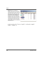
1
Reconstruct Serial Sections User’s Manual Updated: 3/1/06 © John C. Fiala • • • • CHAPTER 1 Quick Start o Getting Started o Create a Series o Import Section Images o Calibrate Pixel Size o Align Sections o Trace Profiles o View Three-Dimensional Object o About the Rest of the Book CHAPTER 2 (TBD) CHAPTER 3 Software Overview o Series, Sections, Domains, Traces, and Objects o Data File Organization XML File Formats Image File Formats o System Requirements Operating System OpenGL Hardware Requirements o History o Credits Source Code Development Tools CHAPTER 4 User Interface o Windows and Dialogs Resizing and Moving Windows Switching Between Windows o Main Window o Main Menu o Tools Window o Status Bar o Section List Window o Thumbnails Window o Domain List Window o Trace List Window o Trace Palette Window o Object List Window o 3D Scene Window o Z-Trace List Window o Distance List Window Exiting or Aborting CHAPTER 5 Series o Creating a Series o Opening and Closing Series o Saving a Series o Series Options o Exporting and Importing Images o Exporting Trace Lists o Importing Line Drawing o Importing Series Data CHAPTER 6 Sections o Section Indexing o Creating a Section o Saving a Section o Displaying a Section Centering Zooming and Panning o Paging Sections o Blending and Flickering Sections o Listing all Sections o Editing Section Attributes Movement Lock Thickness Section Numbering o Deleting Sections o The UNDO Stack o Thumbnails o Exporting Section Images CHAPTER 7 Domain Images o Creating a Domain Importing Multiple Images o Listing Domains o Selecting a Domain o Merging a Domain o Moving and Montaging Domain Images o Domain Boundary o Domain Attributes Name Source Pixel Size Contrast and Brightness o Reinitializing a Domain Contrast Boundary Transform o Hiding Domains o • • • Proxies Proxy Rule of Thumb for Single Domains CHAPTER 8 Traces o Creating a Trace Ellipse Tool Rectangle Tool Line Tool o Selecting Traces Selection Tool Deselecting Traces Zooming to Selected Traces o Trace List o About Trace Names o Trace Attributes Name Comment Hidden Simplified Closed Border Color Fill Color Fill Style o Trace Clipboard o Setting Trace Attributes for Drawing o The Trace Palette o Stamping Predefined Shapes o Creating a Grid of Traces o Open Point-by-Point Drawing o Closed Point-by-Point Drawing o Freehand Drawing o Editing Traces Scissors Tool Scalpel Tool Merge Reverse Simplify o Wildfire Region Growing Propagating Wildfires to Adjacent Sections Generating Wildfires Throughout a Region o Z-Traces CHAPTER 9 Calibration and Measurement o Units of Measurement Data Precision Image Pixel Size o Calibration Grids and Scale Bars o Calibrating Traces o • • • Drawing Calibration Traces Calibrate Selected Traces Resize Traces, Set Pixel Size, or Scale Section Apply the Calibration to Other Sections o Section Thickness Calibrating Section Thickness o Z Distance o Status Bar Measurements o Domain List Measurements Length Area Midpoint X Midpoint Y o Trace List Measurements Length Area Centroid X Centroid Y Min X Min Y Max X Max Y Z Position Thickness o Object List Measurements Count Surface Area Flat Area Volume o Z-Trace List Measurements Length o Distances List Computation Algorithm CHAPTER 10 Movements and Alignments o Transformations o Keyboard Increments o Movement Type-In Dialog o Undoing Movements o Repeating Movements Propagate Repeating Movement Sequences o Alignments Aligning Selected Traces Aligning Entire Sections o Evaluating Alignments o Undoing and Adjusting Alignments Repeating an Alignment Montaging Domains by Point Correspondences Aligning By Correlation Tips for Aligning Sections Section the material appropriately Beware of ambiguous alignments Avoid aligning the same features everytime Don't over-align Avoid quadratic aligns Choose the starting point carefully One Strategy CHAPTER 11 Objects o The Object List o Changing Object Attributes o Renaming Objects o Copying Objects o Hiding and Unhiding Objects o Simplifying Objects o Deleting Objects o Calculating the Distances Between Objects o 3D Object Representations Traces Trace Areas Trace Midpoints Box Boissonnat Surface Cylinder Ellipsoid Sphere 3D Parameters Shift Object By Surface Normals Faceting Density Size Boissonnat Surfaces o Z-Trace List CHAPTER 12 The 3D Scene o OpenGL Rendering o Composing a Scene Adding Objects Removing Objects Changing Object Appearance Diffuse Color Emissive Color Ambient Intensity Transparency o o o o • • • • • Specular Color Shininess Filled or Wireframe Faces o Viewing a Scene Rotating, Panning, and Zooming Spin Background Color o Saving a Scene VRML 2.0 VRML 1.0 DXF Bitmap JPEG o Scene Information CHAPTER 13 (TBD) Bibliography Appendices o Keyboard Overlay CHAPTER 1 Quick Start This chapter gives the steps for reconstructing serial sections. You will learn the basics of using Reconstruct to import a series of images, view and align the sections, trace profiles, and generate a 3D view of the traces. Getting Started The only requirements for getting started are that the Reconstruct application is installed and that a set of image files is available for input. To install the software download the latest version from http://synapses.bu.edu/ or from the Users Group http://groups.yahoo.com/group/reconstruct_users/files/. Run the downloaded file and a dialog should appear asking you whether you want to install Reconstruct. Select Yes and proceed through the installation dialogs until the process is complete. To test your installation, start Reconstruct and select Open... from the Series menu. If this is the first time you’ve installed and used Reconstruct, a series file called example.ser should be visible in the Open dialog. Open the example series. When Copyright © 2006 John C Fiala 1 Quick Start the series opens you should see some text on the screen. Follow these text instructions to get familiar with the basic operations of Reconstruct. This chapter only covers a small fraction of Reconstruct functionality. To get a better idea of the full functionality, review the Key and Mouse commands listings available on the Help menu. Then open the Options... dialog from the Series menu and review the contents of all the Options tabs. This will give you an idea of what features of the program can be reconfigured to suit your purpose. Details about these features can be found in subsequent chapters. CREATE A SERIES Start the Reconstruct program and from the Series menu select the New menu item. A file open dialog will appear. Navigate to a folder on the hard drive where the new series files can be written. If desired you may create a new folder from this dialog. The word “newSeries” should appear in the Filename box near the bottom of the dialog. This will be the name of the series files created to store the series data. Select the Save button in the New Series dialog to create the series. IMPORT SECTION IMAGES Import section images into the series using the Import Images item from the Series menu. This will open a dialog for creating the section files from a set of image files (Fig. 1.1). Image files can be in a variety of formats including Windows Bitmaps, GIF, TIFF, and/or JPEG. Each image file should contain a single image (not an image stack) representing one section in a series, and should use a representation of 8 or 24 bits per pixel. Choose image files using the Select button. This button will open a file selection dialog. In this dialog navigate to the folder containing the image files and highlight the image files using the mouse. Multiple files can be highlighted using the Ctrl or Shift keys. The filenames will appear in quotes in the Filename box when multiple files are selected. When all desired images have been selected, use the Open button to transport the filenames into the Import Images list. 2 Reconstruct v1.0.6.1 Getting Started Figure 1.1. The Import Images dialog box after images have been selected using the Select button. Since the file names contain the section index, automatic numbering is realized by having a -1 specified in the First Section box. Figure 1.1 shows the Import Images dialog after some images have been selected. The source directory is given at the top of the dialog. The filenames of recognized image files and their formats are listed in the left-most columns of the list. The third column gives the section number to which each image will be imported. Set the first section number of the sequence by typing the number, typically 1, in the First Section box. If the sections are not numbered correctly and the filenames contain numbers indicating the correct order, you can use the Sort Numerically checkbox to reorder the files in the list. For finer control of section numbering you may have to import images in stages. Create the section files by selecting the Import button in the dialog. As the image files are added to the series they will be deleted from the list. After the images have been imported you can repeat the process to add more images to your series. When all images have been added, use the Quit button to close the Import Images dialog. To view the sections, open the List... from the Section Menu and double-click on one of the listed sections. This will move the display to that section in the series. Press the Home key. After a brief delay, the image of the first section will be centered in the main window. Use the Page Up and Page Down keys to advance sec- Reconstruct v1.0.6.1 3 Quick Start Figure 1.2. The Tools window. This window should be visible at the top of the Reconstruct main window. Use the left mouse button to select a tool. The Line Tool used for calibration lines is the 8th button. The Pencil Tool is the 10th button. The Wildfire tool button is depressed and so a description of the tool appears in the title bar. tion by section through the series. Verify that the images were imported as expected with the correct section numbers. The number of each section appears in the title bar of the main window. CALIBRATE PIXEL SIZE An important parameter during image import is the pixel size, which we ignored in the previous section. This parameter specifies the size of image picture elements (pixels) in terms of the units of measure of the series (Chapter 9). If the pixel size in the Import Images dialog was accurate, no further calibration is required. However in most cases the pixel size should be adjusted using the image of a calibration grid or scale that was photographed with the series. This is best done before any alignments or tracing, since changing the pixel size later can invalidate these adjustments. The process of calibration in Reconstruct involves drawing traces of known length and then entering that length value into the program. Select the Line Tool (Fig. 1.2) from the tools window and draw a line trace of known length on a section containing a calibration grid image. (For more details on calibration grids and lines see Chapter 9.) After the calibration trace is drawn, select the Calibrate item from the Traces menu. A dialog box will appear for each calibration trace displaying the current length of the trace. Enter the actual length of the trace in place of the current length. 4 Reconstruct v1.0.6.1 Getting Started Figure 1.3. The Calibrate dialogs as filled out for a global calibration of the pixel size of images. Left: The first dialog requests that a pixel size calibration be done for the image on which the calibration lines were traced. Right: The next dialog allows this same pixel size to be applied to every image in every section of the series. When the lengths for all selected traces have been entered, a Calibrate Traces dialog will appear (Fig. 1.3) offering three options. Select the second option to set the correct pixel size for the current section. When the “Set Pixel Size on All Domains?” dialog appears, set the First Section to the first section of the series and the Last Section to the last section. Verify the value in the “Set pixel size to...” box and click the OK button. This will set the pixel size of all images in the series to the value determined from the calibration image. The pixel size for any image can be verified by using the Domain List while viewing the section in the main window. Note that after calibration of pixel size, the calibration lines are no longer accurately matched to the calibration image on which they were drawn. This is to be expected. Since these calibration lines are no longer useful they can be deleted from the calibration section. An additional check on the calibration would be to redraw one or two calibration lines and verify that their length is now correct. ALIGN SECTIONS Tissue that has been physically sectioned and then imaged must be realigned for accurate 3D measurements and visualizations. Section images can be manually moved into relative alignment using keyboard commands (Chapter 10), but it is usually much easier to align sections by specifying correspondence points and using the Align command from the Trace menu. This option is outlined in the fol- Reconstruct v1.0.6.1 5 Quick Start lowing steps. It will only work if appropriate landmarks are visible in adjacent sections. For best alignment results, read Chapter 10. Step 1. Go to a section which will serve as the stationary reference. Then page to the adjacent section that will be aligned to the stationary one. Press the ‘/’ key to switch between the two sections. Step 2. In the Trace menu, select Palette to open the trace palette window. Click on the first palette button and pick up the Stamp Tool from the tools window. (It is assumed that this is the default palette for a new series such that the first palette button is an orange circle with the default name “a$+”.) Step 3. Use the Stamp Tool to place traces at points to be aligned. Use the ‘/’ key to alternate between sections as points are entered. Enter the landmarks in the same order on both sections so that traces of corresponding points will be numbered the same. To delete a point if you make a mistake, use Ctrl-D to deselect all the points, pick up the Arrow Tool (1st tool button) and select the point to be deleted, then use the Delete key to delete it. Use Ctrl-S to reselect all the points to be aligned. Step 4. After entering 3 or 4 correspondence points, switch to the section that will be moved. Verify in the title bar that the stationary section is not displayed. Step 5. Choose Linear from the “Align section” submenu of the Traces menu. When the section is not unlocked this submenu will be titled “Align traces” instead of “Align section”. Enter Ctrl-L to unlock section movement. The status bar will display an open lock image. If traces are accidentally aligned instead of the images, use Ctrl-Z to undo the trace movement. If the message “Alignment needs more traces” is displayed, make sure you have entered at least 3 points on each section and that all points are selected (Ctrl-S) on both sections. If this message still appears make sure the corresponding traces in each section have the same name. In other words, “a1” in section 1 must be matched to a trace “a1” in section 2, “a2” must match “a2”, and so on. Step 6. After Align Section - Linear has moved the section, use ‘/’ or blend (spacebar) to confirm that all parts of the section are aligned (Chapter 10). If the alignment is acceptable, lock (Ctrl-L) the section to prevent further movements. 6 Reconstruct v1.0.6.1 Getting Started Step 7. If the alignment is not acceptable, use Ctrl-Z to undo the movement. Check the names and positions of the traces entered and modify or add traces as needed. Go to Step 5. As a last resort, delete all traces by entering Ctrl-S followed by the Delete key. Do this for each of the two sections and then start over with Step 3. Step 8. Once the alignment is acceptable you can delete the alignment traces from both sections. If you decide to keep the alignment traces for later editing, you will need to switch the color and name of future correspondence points to avoid confusion with the existing ones. Switching to a new trace name ensures that traces with the same numbering will be created on both sections. To switch correspondence point names, simply select the second button on the trace palette. Later, when you repeat this step after aligning the next section, go back to the first palette entry, alternating between trace names after each alignment. Step 9. Page Up (or Down) to the next section to be aligned and go to Step 3. TRACE PROFILES Information about sectioned objects is created by tracing the profiles of the objects on the sections. To do this, return to the first section in the series by using Page Down or by selecting the first section in the list generated from the List item of the Section menu. From the Series menu, select Options. This opens a dialog that will allow you to configure the default parameters for tracing. Select the Names/Colors options tab at the top the dialog. Put the cursor in the Name edit box and type a name for the object to be traced, such as “myObject”. This will be the name given to the profiles you draw. All profiles with the same name are considered part of the same object. Hit Enter or select the OK button to close the Options dialog. The Tools window (Figure 1.2) should be visible at the top of the main window. Use the cursor to select the tool button that looks like a pencil. The cursor will change to a pencil when the cursor is moved back into the main window. Reconstruct v1.0.6.1 7 Quick Start Figure 1.4. Drawing a trace with the freehand drawing tool. (left) Start of the tracing. Th pencil is positioned at the profile to be traced and the left mouse button pressed and hel down. (middle) Just before release of the mouse button. The pencil left a trail where it was moved with the mouse from the start position. (right) Right after release of the mouse button. The trace is closed and filled with color. Place the tip of the pencil on the edge of the profile to be traced as shown in Figure 1.4). Press and hold down the left mouse button. Drag the tip of the pencil around the profile and release the mouse button when the tip gets near the start of the trace. The trace will be completed (closed) and filled with a color (provided the interior of the profile is not too dark.) Press the Page Up key to advance to the next section. The trace on the previous section will be saved automatically as long as the default save options were not changed in the Series Options dialog. Repeat the process of tracing the profile with the mouse. Continue paging and tracing until several sections have been traced. Use the Page Down button to go back and verify that the data was saved correctly. VIEW THREE-DIMENSIONAL OBJECT Select List from the Object menu to see the list of objects defined by traces in the series. Use the left mouse button to double-click the object name in the list (or use a single mouse click and select Add from the Scene menu at the top of the list window.) A three-dimensional view of the object traces will appear in a 3D Scene window after a brief delay. You can rotate the object representation by placing the mouse in the 3D Scene window and pressing and dragging with the left mouse button. You 8 Reconstruct v1.0.6.1 About the Rest of the Book can zoom in or stop the object’s spin by pressing the right mouse button. Pressing both mouse buttons together allows you to pan the scene. To surface the object, open the Series Options dialog and select the 3D tab. In the 3D options, change the Generate option from Traces to Boissonnat surface and click OK. Go back to the Object List window and again double-click on the object name. The object will be surfaced and replace the trace representation in the scene. Note that traces must conform to certain criteria for Boissonnat surfacing to work correctly. For example, traces of the same object within a section cannot overlap. For a detailed discussion of tracing rules related to Boissonnat surfacing see Chapter 11. About the Rest of the Book This concludes the Quick Start tutorial. To take full advantage of the software, be sure to read the remaining chapters as well. Note: Spending an hour skimming through all the chapters could save you many hours of frustration. Chapter 3 gives an overview of how data is organized and stored, and includes technical details on the system requirements and file formats. This chapter introduces the basic data elements: series, sections, domains, traces, and objects. Chapters 5-8 describe how these data elements are created, edited, saved and deleted. Chapter 4 describes the user interface and includes important information on what particular keystrokes and mouse buttons do in the various program windows. This information is also available from the Key and Mouse Commands help menu items. Chapter 9 explains in detail how to set and calibrate the units of measurement used in Reconstruct. This chapter explains the meaning of the image pixel size parame- Reconstruct v1.0.6.1 9 Quick Start ter and how its value can be accurately determined. Chapter 9 also explains how to get quantitative measurements of the traces created on serial sections. Chapter 10 covers movements of section data, including all the operations that aid in aligning sections. Chapters 4-9 are required reading to understand how to use the full capabilities of the software. Chapter 10 is necessary only if sections or traces will be moved or aligned. Chapters 11-12 cover 3D object visualization. In Chapter 11 the representation and editing of objects is discussed, as well as the methods for generating 3D shapes. The 3D Scene window and the rendering of reconstructed objects is covered in Chapter 12. 10 Reconstruct v1.0.6.1 CHAPTER 3 Software Overview Reconstruct was developed from years of experience working with high magnification serial section images of brain tissue. In this work, brain tissue is embedded in resin and serially-sectioned on an ultramicrotome. Sections are mounted on coated slot grids and photographed in the electron microscope (EM). Since each section is imaged separately in the microscope, the images must be brought back together to understand the structure of the whole tissue. Reconstruct aids in the extraction of three-dimensional (3D) information from the serial section images. Series, Sections, Domains, Traces, and Objects Serial section microscopy consists of an ordered set of sections, representing the sequential pieces of the tissue block. Data in Reconstruct are organized around this concept. An ordered set of sections is called a series. Reconstruct operates on one series at a time. Within a series, data are grouped by section and each section is given an index indicating its position within the series. Each section in the series contains the data related to one physical section of the tissue. The section data includes images of the section and traces drawn on these images. The traces are later grouped together across sections to form 3D objects. Copyright © 2006 John C Fiala 11 Software Overview Figure 3.1. The mapping of data elements onto the section. The contents of this section are two domains (“domain1” and “domain2”) and one trace named “dendrite”, composed as shown in the upper left. Each trace and domain is associated with an independent transformation that determines the size and location of the element on the section. In this example each domain has a rectangular boundary that defines the area of the image to be displayed. Reprinted from Fiala (2005). Each image within a section is called a domain, reflecting that it has a defined boundary and independent position within the section. Multiple image domains can be placed side-by-side within a section to make a montage, a composite picture of the section from many small images. Images are entered into the computer by digitizing photographic prints, negatives, or by direct digital imaging with a digital camera. For example, the negatives on EM film are typically scanned at 1000 dpi using a conventional desktop scanner. These files are saved as Bitmaps or TIFFs from the scanner software, usually with a number in the filename indicating the section number. The image files are then imported into Reconstruct as domains within the sections. 12 Reconstruct v1.0.6.0 Data File Organization Reconstruct is designed to facilitate image cropping, scaling and alignment. Cropping is achieved by drawing a new domain boundary that specifies the region to be displayed on the section. Image scaling is specified by a pixel size (magnification) parameter. Alignment is realized by a non-linear transformation associated with the image. All this information is stored with in the section. In addition to the images and transformations, polygons within the section specify object profiles on the image data. These traces are added to the sections by drawing with a mouse (or a pen on a Tablet PC). All the traces that share the same name belong to the same 3D object. This convention allows the 3D objects to be extracted from the section files by grouping together all the traces with the same name. Objects are thus represented by the traces in the sections. Objects can be split apart or combined together simply by renaming the traces. Data File Organization The data for each section (images and traces) is saved to a file indexed by the section number as the filename extension. A series with 100 section would have 100 section data files, numbered sequentially 1 through 100. For a series named “myseries”, the section data is stored in files named “myseries.1”, “myseries.2”, “myseries.3”, and so on to “myseries.100”. All the section data files are stored in the same folder or directory. Information about the whole series (e.g. option settings) is stored in a separate series data file in this same folder. The series data file has a .ser file extension, e.g. myseries.ser. Thus, the data files associated with a series reside in the same folder and share the same filename. Only the file extension is different, .ser for the series data file and a positive integer for each section data file. The image data itself is not stored in the section data file. For each domain in the section there is a reference to the corresponding image file. The actual image data can be stored anywhere on the computer, but generally it is best to store the image files in the same folder as the section data files. This allows the entire series to be easily off-loaded to CD-ROM or other archival media, and restored at a later date. Reconstruct v1.0.6.0 13 Software Overview <!ENTITY <!ENTITY <!ENTITY <!ENTITY <!ENTITY <!ENTITY <!ENTITY % % % % % % % SFBool SFColor SFFloat MFFloat SFInt32 SFString MFVec2f "(true|false)"> "CDATA"> "CDATA"> "CDATA"> "CDATA"> "CDATA"> "CDATA"> <!ELEMENT Contour EMPTY> <!ATTLIST Contour name %SFString; hidden %SFBool; closed %SFBool; simplified %SFBool; border %SFColor; fill %SFColor; mode %SFInt32; comment %SFString; points %MFVec2f; "unknown" "false" "true" "false" "1 0 1" "1 0 1" "9" #IMPLIED #IMPLIED> <!ELEMENT Image <!ATTLIST Image mag contrast brightness src proxy_src proxy_scale "1.0" "1" "0" "" "" "1.0"> EMPTY> %SFFloat; %SFFloat; %SFFloat; %SFString; %SFString; %SFFloat; <!ELEMENT Transform ((Image,Contour)|Contour+) > <!ATTLIST Transform dim %SFInt32; "6" xcoef %MFFloat; "0 1 0 0 0 0" ycoef %MFFloat; "0 0 1 0 0 0"> <!ELEMENT Section (Transform+)> <!ATTLIST Section index %SFInt32; "-1" thickness %SFFloat; "0.05" alignLocked %SFBool; "false"> Figure 3.2. The Document Type Definition of the section data file (section.dtd). 14 Reconstruct v1.0.6.0 Data File Organization XML FILE FORMATS Reconstruct uses XML (eXtensible Markup Language, www.xml.com,) for representing series and section data. XML files are in plain ASCII text and are therefore readable by text editors. XML can also be validated, allowing errors in the files to be automatically detected. A Document Type Definition (DTD) specifies the format for a valid file. For Reconstruct there are two DTDs, one for the section data file and one for the series data file. By including a reference to the DTD in the header of the XML data file, an XML validator can determine whether the syntax of the data file is correct. The section DTD (Fig 3.1) specifies the XML file format for all section data files. The basic data types are defined by the ENTITY descriptions, referenced later by the % sign. SFBool defines a single field Boolean, either “true” or “false”. SFColor is an RGB color defined by 3 floats where 0 0 0 is black and 1 1 1 is white. SFFloat is a single 32-bit floating point value. MFFloat is an array of floating point values separated by white space. SFInt32 is a single 32-bit integer value. SFString is a string of characters excluding the characters , " = / < and >. MFVec2f is an array of pairs of floats specifying (x,y) coordinates on the section. The rest of the DTD defines the basic ELEMENTS of a section and their attributes. A section contains one Section data element. The Section has three attributes, an index specifying the position of the section in the series, a thickness specifying the section thickness, and an alignLocked flag that specifies whether the entire section can be moved. The Section may contain one or more Transform elements. The Transform element contains the coefficients of the linear combination of the bivariate polynomial basis, and a dim parameter specifying how many of these terms are to be used. Each Transform element contains either an Image element and boundary Contour, or a set of Contour elements. The Image element is the reference to an image file. Image attributes are mag, the width of a square pixel in series units; src, the path to the file containing the image data; contrast and brightness operate on a virtual intensity range of [0,1]; proxy_src, the path to a file containing image data at reduced dimensions; proxy_scale, the dimension of the proxy image divided by the dimension of src Reconstruct v1.0.6.0 15 Software Overview <?xml version="1.0"?> <!DOCTYPE Section SYSTEM "section.dtd"> <Section index="7" thickness="0.05" alignLocked="true"> <Transform dim="6" xcoef=" 0.240299 0.999416 -0.0182671 0 0 0" ycoef=" 0.0104287 0.0297386 0.997894 0 0 0"> <Image mag="0.002691" contrast="1" brightness="0" src="_unaligned.7" /> <Contour name="domain1" hidden="false" closed="true" simplified="false" border="1 0 1" fill="1 0 1" mode="11" points="0 0, 768 0, 768 768, 0 768, "/> </Transform> <Transform dim="0" xcoef=" 0 1 0 0 0 0" ycoef=" 0 0 1 0 0 0"> <Contour name="a4" hidden="false" closed="true" simplified="false" border="1 0.5 0" fill="1 0.5 0" mode="13" points="0.377196 0.55957, 0.377196 0.555605, 0.381161 0.55164, 0.385125 0.55164, 0.38909 0.555605, 0.38909 0.55957, 0.385125 0.563534, 0.381161 0.563534, "/> </Transform> </Section> Figure 3.3. An example XML section data file. Section number 7 consists of one image domain “domain1” and one trace “a4”. 16 Reconstruct v1.0.6.0 Data File Organization image. The Contour element paired with an Image element is the set of points defining the boundary of the image domain. A Contour element is the set of points defining a trace on the section. The Contour element contains no other elements but has many attributes: name, the identifier of object to which the trace belongs; hidden, whether trace is displayed; closed, whether the trace closes on itself; simplified, whether trace points have been simplified; border, the displayed color of the polygonal representation; fill, the color of the interior of the trace when filled; mode, the type of filling operation used; comment, a string of user information; points, the sequence of (x,y) coordinates of of the trace. Fig 3.2 shows a valid XML section data file based on the DTD. Note that a similar DTD is defined for the series data file (series.dtd), but it is not expounded here because the large number of series options makes the file very long. To read the DTD format, open the series.dtd file using any text editor. IMAGE FILE FORMATS Reconstruct currently supports several common single image file formats including Windows Bitmaps, JPEG, TIFF, and GIF. The complete set of acceptable file formats is determined by the image input/output library developed by Andy Key (see Credits, below). These include Windows and OS/2 bitmaps (.BMP .VGA .BGA .RLE .DIB .RL4 .RL8) except for CCITT G3 MH Fax compressed and 24 bit RLE files, CompuServe GIF files (.GIF), JPEG File Interchange Format files (.JPG .JPEG .JPE), TIFF files (.TIF .TIFF) with 1, 4, 8 and 24-bits per pixel, Truevision Targa/Vista bitmaps (.TGA .VST .AFI), ZSoft PC Paintbrush Image format (.PCX .PCC), GEM Raster (.IMG), Portable Greyscale-map (binary P5 type) (.PGM), and Portable Pixel-map (binary P6 type) (.PPM). For most formats it is required that the image filename extension reflect the file format used. For example, a portable pixel-map file could be named “myimage.ppm” but not “myimage.junk”. Exceptions to this rule are the common formats: Windows Bitmap, JPEG, TIFF, and GIF. The filenames for these formats is Reconstruct v1.0.6.0 17 Software Overview arbitrary because the program can identify the file format from header information in the file. System Requirements Reconstruct was written and tested under Microsoft Windows XP on a Dell Optiplex GX260 Pentium 4 (2 GHz) computer with 512 Mb of RAM. The Reconstruct binary executable is compiled for Pentium-compatible processors, and the application relies entirely on the Win32 libraries for interacting with the computer’s user interface. Reconstruct will therefore run on any Pentium-compatible computer that supports Win32. OPERATING SYSTEM Reconstruct will run on all Microsoft Windows operating systems: Windows 95, Windows 98, Windows 2000, Windows NT, and Windows XP. Reconstruct will run under other operating systems provided a Win32 emulator/ translator is installed. A Win32 translation layer for X Windows, such as WINE (www.winehq.com), translates the Win32 API calls from Reconstruct into the equivalent X Windows operations. WINE is available for a variety of operating systems, including GNU/LINUX, FreeBSD, and Solaris. Users have verified WINE for running Reconstruct under Mandriva Linux w/KDE 3.3.2. In addition, the Reconstruct binary may run on Virtual PC, Apple’s Pentium/Windows emulator, but this has not been tested. OPENGL OpenGL libaries are required for previewing (and saving) 3D objects. The OpenGL libraries provide a software interface to the computer’s graphics hardware. OpenGL is shipped standard with every version of Windows (95/98/2000/ NT/XP) and should work with Reconstruct without any additional configuration. For more information on OpenGL see Chapter 12. 18 Reconstruct v1.0.6.0 System Requirements HARDWARE REQUIREMENTS Performance of Reconstruct is determined by three main hardware components: the graphics display adaptor, the amount of RAM, and the speed of the hard drive. A high-quality graphics display adaptor that accelerates OpenGL is highly desirable for 3D Scene operations. Most modern game adaptors are satisfactory for this purpose. The software was tested on a Radeon VE adaptor with 32 Mb of memory. This device gave excellent OpenGL performance. Reconstruct is not a very demanding application from a memory standpoint because the data from only two sections is held in memory at one time. Thus, a very long series of hundreds of sections will not require any more memory than a short one. A minimum requirement for good performance is free RAM equal to a least 3 times the total amount of data on a section. Thus, if a section contains 40 Mb of image data, 40+40+40=120 Mb of RAM would be needed for running the program. Allow for an additional 128Mb for the Windows XP operating system and desktop, along with 20-40 Mb for each major application (Acrobat, Outlook, Word, Excel, etc.) to used simultaneously with Reconstruct. 512Mb of memory was adequate for all data used to test the software. The greatest performance enhancer is a fast hard drive. Note that hard drive performance is not necessarily the transfer rate given in the hard drive specifications. This Data Transfer Rate is usually a burst rate for the interface to the system memory, not the actual speed of data access from the drive. Look for drives with the highest speed of rotation (RPM) and the most sectors per track. Real sustained data transfer rates are roughly proportional the product of rotational speed and sectors per track. For example, a 15,000 RPM SCSI drive will outperform a 5,400 RPM IDE/ATA drive, resulting in faster loading and paging of sections in Reconstruct. A 7,200 RPM IDE/ATA drive was used during development and testing of the software. A 7200 RPM drive gives satisfactory performance on images less than 15 Mb. Reconstruct v1.0.6.0 19 Software Overview Figure 3.4. The welcome page for the Reconstruct Users Group at Yahoo! Groups. History The origins of Reconstruct began in 1995 with the development of a Windows 3.1 program for tracing serial sections. WinV8 was developed in the Image Graphics Laboratory at Children's Hospital, Boston, as a continuation of the DOS-based V8 program developed by John Davis. Very quickly WinV8 was replaced by a new Win32 application, IGL Trace. Version 1.0a of IGL Trace was completed in August of 1997, with NIH funding to the Mental Retardation Research Center at Children’s Hospital. IGL Trace has proven useful for identifying, tracing, measuring, and reconstructing 3D objects in serial sections in a number of scientific studies. IGL Trace was designed to operate on aligned sections. These can be images obtained from electron or light microscopy. For electron microscopy, where each section is imaged separately, it is necessary to realign the images for accurate reconstructions. IGL Align, also developed in the Image Graphics Laboratory, was a first attempt at aligning grayscale images. Funding from NIH's Human Brain Project to Children's Hospital allowed the development of a more sophisticated alignment program, sEM Align, in 1999. sEM Align was developed to allow on- 20 Reconstruct v1.0.6.0 Credits screen alignment of larger images than was possible through the use of IGL Align. This is accomplished by displaying and moving scaled versions of the original images on screen. Images can be incrementally moved using keyboard input or alignments can be computed from a set of feature correspondences specified by the user. To use the alignments computed by sEM Align, a new set of aligned images are rendered for input into IGL Trace. Most of the functionality of sEM Align and IGL Trace is incorporated into Reconstruct. By combining alignment and tracing into one program, Reconstruct allows images to be processed more efficiently. Tracing can be done directly on the transformed images and alignments can be easily modified. Converters are available to convert existing sEM Align and IGL Trace series to ones compatible with Reconstruct. See the synapses.bu.edu website for details. Reconstruct development was funded, through April, 2004, by NIH's Human Brain Project. A Users Group was created at that time to continue to support the Reconstruct user community. The Reconstruct Users Group is available to everyone at “http://groups.yahoo.com/group/reconstruct_users/”. Development of the software has also continued through the suggestions of users and the donation of programming time by Dr. Fiala. A Reconstruct Developers Group has been established at “http://groups.yahoo.com/group/reconstruct_developers/” to provide a forum for collaborative, open-source development. Credits The development of Reconstruct was funded, in part, by the National Institutes of Health under grants (P30 HD 18655, R01 MH/DA 57351, R01 EB 002170, RO1 NS024760 and RO1 MH057414). A number of different people contributed ideas for the user interface and behavior of the software. In addition, a number of free programming resources were used in the production of Reconstruct, as acknowledged below. Reconstruct v1.0.6.0 21 Software Overview SOURCE CODE The majority of Reconstruct was designed and written by John Fiala ([email protected]). Other contributors are listed in the License dialog of the Help menu. The contributions of these individuals are as follows: Andy Key and the Independent JPEG Group. Image input and output was realized by incorporating the Generalized Bitmap Module (GBM) library written by Andy Key (http://www.nyangau.fsnet.co.uk/). These libraries incorporated the source code of the Independent JPEG Group (http://www.ijg.org/) written by Thomas G. Lane for handling the JPEG/JFIF image formats. Stefan Gustavson. Provided the ANSI C port of the complex FFT that is used for image correlations. Ju Lu. Implemented the section-to-section propagation of wildfires. Anyone may contribute to the next version of Reconstruct by joining the Reconstruct Developers Group at “http://groups.yahoo.com/group/ reconstruct_developers/”. Members of the Developers Group gain access to the source code and may participate in developing the next version of Reconstruct. The developers group also provides additional information and links to the free development tools used for creating the application. DEVELOPMENT TOOLS Reconstruct was created using a minimalist approach to development. As a consequence all of the essential tools used to develop Reconstruct are free. Reconstruct does not rely on propriety libraries, or particular commercial compilers and integrated development environments. The following free resources were the principal development tools used. For more information, please consult the Reconstruct Developers Group. Borland. The program was compiled and linked using the Borland 5.5 Free Command Line Tools and Standard C libraries (http://www.borland.com/). 22 Reconstruct v1.0.6.0 Credits Jeremy Gordon. Borland’s free resource compiler did not support all the desired features, like animated icons in dialog resources. Luckily, Jeremy Gordon has a better resource compiler (GoRC) that was freely available (http://www.godevtool.com/). GoRC was used to compile the resource file prior to linking with the Borland linker. Microsoft. Microsoft development tools were not used, the only exception being the Microsoft Help Workshop compiler for converting .rtf files into Windows Help files. Open Watcom. Another useful resource was the publicly available suite of development tools from Sybase (http://www.openwatcom.org/). The Open Watcom Image and Resource editors were used to produce the cursors, icons, and many of the other resource elements. Subversion. For source code version control Reconstruct development is now using Subversion (http://www.subversion.org/). This software allows multiple developers to coordinate their changes through an internet accessible source code repository residing on the synapses.bu.edu server. Jordan Russell. Finally, thanks to Jordon Russell for his wonderfully welldesigned InnoSteup (http://www.jrsoftware.org/), used to create the final installation file. Reconstruct v1.0.6.0 23 Software Overview 24 Reconstruct v1.0.6.0 CHAPTER 4 User Interface The user of Reconstruct interacts with a set of screen elements using the mouse (or pen) and keyboard. This chapter describes the basics of this graphical user interface. Windows and Dialogs Two kinds of screen elements will be distinguished: windows and dialogs. Dialogs must be completed prior to returning to the main window, while windows release control to each other. The exception to this is that some message dialogs (such as the Version dialog from the Help menu) release control back to the main window. Dialogs cannot be resized but can be moved. Windows float on top of the application. They can be resized and moved, but not minimized independently of the application. A special case is the status bar that is not moveable but remains docked at the bottom of the window. Copyright © 2006 John C Fiala 25 User Interface RESIZING AND MOVING WINDOWS Windows can be resized by placing the pointer on the narrow border of the window, pressing the left mouse button, and dragging the border. The pointer should change to resize arrows when over the border of a realizable window. The main window can also be resized by dragging from the resize area in the lower righthand corner of the status bar. Both windows and dialogs can be moved by dragging the title bar with the left mouse button. Windows that display an icon in the title bar, namely the main window and the Series Options window, can be moved with the keyboard. Selecting the icon with left mouse button opens the system menu. To resize or move the window select the menu item and then use the arrows keys to adjust the position of the window. Holding the Ctrl key down allows finer control of the movements. Release the keyboard mode by hitting Enter or by pressing the left mouse button again. Changes can be canceled with the Esc key. SWITCHING BETWEEN WINDOWS The keyboard focus can be switched between windows of the application by using Ctrl-Tab, much in the same way as the Alt-Tab command is used to switch between active applications on the desktop. The window that has the keyboard focus is called the active window. An active window usually has a colored title bar while inactive windows often have grayed title bars. TABLE 4.1. Basic 26 Keyboard and Mouse Actions for All Windows Keystroke Alt Alt-Tab Ctrl-Tab Action Access the menu of the currently active window Switch between applications Switch between floating windows of the application Left Mouse Drag on title bar on border Action Position the window Size the window Reconstruct v1.0.6.1 Main Window Title Bar Buttons Main Menu Tools Window Main Window Status Bar Figure 4.1. Reconstruct’s initial window layout. A main window with a narrow border and a black interior is overlaid with a floating tools window and a status bar. Main Window When the application is started the Reconstruct main window appears along with two of the sub-windows, the tools window and the status bar (Fig 4.1). The main window consists of a title bar at the top, a set of menus beneath the title bar, and a rendering area (a.k.a. client area) for displaying data. At the left end of the title bar is the Reconstruct icon. When a series is open the series name is displayed in the title bar along with the current section number. On the right end of the title bar are the usual minimize, maximize, and close buttons. Selecting the minimize button, by clicking the left mouse button when the pointer is over the button, hides the window. The hidden window can be reopened by selecting it on the task bar or by using Alt-Tab (pressing the Tab key while holding the Alt key down.) Alt-Tab can also be used to rapidly switch between Reconstruct and other applications running on the desktop. The maximize button resizes the main window to fill the screen. The main window cannot be manually resized when it is maximized. Unmaximize the window by the selecting the maximize button again. A number of keystrokes and mouse actions can be used in the main window (Table 4.2). These are mostly for navigating between sections in the series and creating or Reconstruct v1.0.6.1 27 User Interface manipulating section data. Mouse actions in the main window may depend on the which tool has been selected from the tools windows. These actions are discussed in more detail in Chapters 5-8. However, moving the mouse wheel has the same effect as Page Up and Page Down in the main window. TABLE 4.2. Keyboard Keystroke Page Up Page Down / Backspace Esc 0, 1, ... 9 Ctrl-0, ctrl-1, ... ctrl-9 F1-F12 keys Arrow keys = [ ] Mouse input and Mouse Actions in the Main Windows Action Display next (higher) section in series Display preceding lower section in series Switch front and back sections. Hold to flicker. Delete last trace point entered when drawing Abandon current drawing or tool operation Switch default trace attributes to palette entry Set the corresponding palette entry to the current default attributes and stamp tool shape Section, domain and trace movements Section, domain and trace movements Decrease brightness of selected domain Increase brightness of selected domain Decrease contrast of selected domain Increase contrast of selected domain May depend on the currently active tool Main Menu The main menu consists of Program, Series, Section, Domain, Trace, Object, and Help open menus. Submenus of these menus are indicated by an arrowhead on the right-hand side of the item. Items that open a dialog requiring further user input are indicated by a trailing “...”. These operations can generally be canceled in the dialog. Other menu items execute immediately. The mouse pointer can be used to select items in the main menu, but menu items can also be selected with the keyboard. Keyboard control of the menu is activated by pressing and releasing the Alt key. When the menu is under keyboard control certain letters in the menu items will be highlighted. These items can be selected by tapping the key for the highlighted letter. For example, pressing and releasing the Alt key and then the T key, will open the Trace menu. The L key will then open the Trace List. Alternatively, the arrow keys can be used to browse through the 28 Reconstruct v1.0.6.1 Main Menu menus.The highlighted menu item can be selected by using the Enter key. The menu selection process can be aborted by using the Esc key. Some menu items have special keystrokes associated with them that allow them to be rapidly executed without using the menu selection process (Table 4.3). For example, pressing the S key while holding down the Ctrl key when the main window is active will select all the traces in the section. Many of the menu items may be grayed or disabled if they are not currently appropriate. For example, if no series is open then the menus for manipulating sections, domains, and traces are not applicable. Likewise the domain and trace menus are mostly disabled when no domain or trace has been selected, since most operations apply to selected data elements. TABLE 4.3. Keyboard Keystroke Space Esc Ctrl-\ Ctrl-A Ctrl-B Ctrl-C Ctrl-D Ctrl-H Ctrl-L Ctrl-M Ctrl-O Ctrl-P Ctrl-R Ctrl-S Ctrl-U Ctrl-V Ctrl-X Ctrl-Z Home Ctrl-Home End Insert Delete Accelerators for the Main Menu Action Blend the front and back section images Abandon current menu selection activity Move front section By Correlation with back section Edit the attributes of selected traces Paste attributes from clipboard traces to selected traces Copy the selected traces Deselect all the selected traces Hide the selected traces Toggle the movement lock on the section Merge the selected traces Open the Series Options dialog Switch to/from precision cursor when drawing Repeat last movement Select all traces on section Undo all current changes to the section Paste traces into section Cut selected traces from section for later pasting Undo section or domain changes Center section image in view Zoom and center selected traces in view Undo/redo last zoom Paste traces into section Delete selected traces or domain Reconstruct v1.0.6.1 29 User Interface Tools Window The Tools Window is a floating toolbar that allows the user to select different modes of mouse input in the main window. The toolbar can be opened or closed by selecting the Tools Window item from the Program menu. The Tools Window can also be closed by selecting the close box on the right-hand side of the title bar. A description of the tool appears in the title bar of the Tools Window whenever the a tool button is pressed. Pressing the tool button also selects the tool for use in the main window. The keyboard can be used to change tools without moving the mouse pointer. To do this give the tools window the focus using Ctrl-Tab. Then use the Tab key to move through the tool buttons. The highlighted button can be selected with the Enter key. The Tools Window can be resized and placed anywhere on the screen. The tool buttons will automatically reorganize to fit within the new window frame. TABLE 4.4. Keyboard Command Tab Enter Left mouse click and Mouse Actions in Tools Window Action Move to next tool button Select highlighted tool Select the tool under the pointer Status Bar The Status Bar can be opened or closed by selecting the Status Bar item from the Windows submenu in the Program Menu. The Status Bar displays information about the data under the pointer when a series is open. The left-most element on the Status Bar is a lock/unlock icon that indicates whether the current section can be moved or aligned (Chapter 6). The Status Bar also contains the number of the section being displayed, the name of the trace nearest to the mouse pointer, and the position of the pointer on the section in series units. On a domain, the Status Bar displays the position of the pointer in image pixels. When drawing, the Status Bar displays the name of trace being drawing and either position, length, or area information for the drawing increment. 30 Reconstruct v1.0.6.1 Section List Window Section List Window The Section List Window is opened by selecting the List item from the Section menu. The section list displays the sections of the series in order of ascending section number. The two attributes of each section can be displayed: the lock/unlock status and the section thickness in series units. The columns of the list can be resized by dragging the column borders with the left mouse. When the section list is open the current section is highlighted. A different section can be displayed in the main window by double-clicking the new section number in the Section List Window. The section list will be closed once a new section is selected. The paging operation can also be executed by selecting the Page To menu item at the top of the Section List Window, in which case the section list is not closed. The Section List Window can also be closed by selecting the List item from the Section menu in the main window. Navigate the section list with the keyboard using the up and down arrow keys, the Page Up and Page Down keys, or the Home and End keys. Use Enter to execute the Page To operation for the first highlighted section. TABLE 4.5. Keyboard Command Up & down arrows Page Up & Down Home End Delete Enter Ctrl or Shift Left Mouse Click Left Mouse Dbl-Click and Mouse Actions in Section List Window Action Move to next/previous section in list Move through the list by the number of visible sections Move to the first section in the list Move to the last section in the list Delete the highlighted sections from the series Page to the first highlighted section Highlight multiple sections for Modify operations Highlight the section under the pointer Page to the section under the pointer Multiple sections can be selected in the section list by holding the Ctrl or Shift key down while selecting sections in the list with the mouse. The highlighted sections can be changed simultaneously using the Modify menu at the top of the Section List window. The Modify operations allow highlighted sections to be locked/ unlocked, renumbered, deleted, or given particular pixel size or thickness attributes (Chapter 6). Reconstruct v1.0.6.1 31 User Interface Each list window has a Save... menu item that allows the list to be saved as a Comma Separated Values (.csv) file. This file is an ASCII text file that can be readily imported into spreadsheet programs such as Excel. The Save... dialog allows the filename and folder for the .csv file to be specified. The list columns and rows will be saved in the file just as they appear in the window. Thumbnails Window Thumbnails images of the sections can be viewed by selecting Thumbnails from the Section menu. Each thumbnail image is placed on a button in the thumbnails window and the buttons are displayed in one of two ways. In the default display mode the thumbnail buttons are arranged to fill the window starting in the upper left-hand corner. Resizing the window results in rearrangement of the buttons to fill the window. Putting the pointer over a thumbnail button for a certain amount of time results in display of the section number in the title bar when the thumbnails window is active. Selecting a thumbnail with the left mouse button results in the main window being activated and paging to the section. The thumbnail buttons cannot be navigated with the keyboard but can be scrolled through using the scroll button on the mouse. For more on the configuration of thumbnails see Thumbnails in Chapter 6. TABLE 4.6. Keyboard Command Tab Enter Left Mouse Click Mouse Scroll and Mouse Actions in Thumbnails Window Action In flipbook mode, stop/start shuttle play In flipbook mode, page to the section shown Page to the section under the pointer In flipbook mode, move through the thumbnails Domain List Window The Domain List Window is opened using the List item from the Domain menu. The window displays a list of all the domains within the section ordered from back 32 Reconstruct v1.0.6.1 Trace List Window to front. The domain name is displayed along with the source path to the image data, the pixel size, and the centroid position of the domain on the section. The columns of the list can be resized by dragging the borders of the column headers. A domain can be highlighted in the list with the left mouse button or by using the arrow keys. The attributes of the highlighted domain can be edited by selecting the Attributes menu item. This action does not close the domain list. Double-clicking the left mouse button or hitting Enter will cause the Select menu item to be executed on the highlighted domain. In this case the domain is selected in the main window and the Domain List Window is closed. See Chapter 7 for more on working with selected domains. TABLE 4.7. Keyboard Command Up & down arrows Page Up & Down Home End Delete Enter Left Mouse Click Left Mouse Dbl-Click and Mouse Actions in Domain List Window Action Move to next/previous domain in list Move through the list by the number of visible domains Move to the first domain in the list Move to the last domain in the list Remove the domain from the section Select the domain from the section Highlight the domain under the pointer Select the domain under the pointer Trace List Window The Trace List Window is opened using the List item from the Trace menu. The window displays a list of all the traces within the section ordered alphabetically. The trace name is displayed along with a set of measurements in series units. The columns of the list can be resized by dragging the borders of the column headers. The set of displayed columns can be specified from the Lists tab in the Series Options dialog. The entire trace list can be saved to a file by choosing the Save... menu item. A trace in the list can be highlighted with the left mouse button or by using the arrow keys. Multiple traces can be highlighted by holding down the Shift or Ctrl keys. Pressing Enter or using the Select menu item will cause the highlighted Reconstruct v1.0.6.1 33 User Interface traces to be selected and the keyboard focus to be shifted to the main window. Any traces that were previously selected in the main window are unselected. TABLE 4.8. Keyboard Command Up & down arrows Page Up & Down Home End Delete Enter Ctrl or Shift Left Mouse Click Left Mouse Dbl-Click and Mouse Actions in Trace List Window Action Highlight next/previous item in list Move through the list by the number of visible traces Move to the first trace in the list Move to the last trace in the list Delete the highlighted traces. Select the trace in the main window Highlight multiple traces Highlight the trace under the pointer Select the trace under the pointer Trace Palette Window The Trace Palette Window can be opened or closed using the Palette item from the Trace menu. The window displays the set of predefined trace attributes as a set of buttons. Each palette entry represents the trace name, border color, fill color, and fill mode for drawing new traces. This is displayed on the button by a trace drawn in the shape of the stamp trace also defined in the palette entry. For more on palette entries see Chapter 8. The Trace Palette Window works much like the Tools Window. It can be resized and placed arbitrarily on the screen. The default trace attributes can be set by selecting the palette entry button with a left mouse click. The Tab key can be used to move through the palette buttons. The highlighted button can be selected with the Enter key. When a palette button is pressed the default trace name of the palette entry is displayed on the title bar. TABLE 4.9. Keyboard Command Tab Enter Left mouse click 34 and Mouse Actions in Trace Palette Window Action Move to next palette entry button Select highlighted palette entry Select the palette entry under the pointer Reconstruct v1.0.6.1 Object List Window Object List Window The Object List is opened or closed by the List item of the Object menu. Each time the list is opened the sections are scanned for traces and these are grouped by name into objects. If there are large numbers of traces and sections, the object list creation may be slow. Each unique trace name is displayed in the list as an object. The list may also display the section range in which the trace name is found, a count of the number of component traces that make up the object, and the object’s surface area and volume. Like the other list windows, the Object List can be navigated by mouse or keyboard. Columns can be resized at the column headings. The window can be resized by dragging the narrow border of the window. Multiple objects can be highlighted by holding down the Shift or Ctrl keys. Hitting Enter or selecting the Add item in the Scene menu will cause a 3D representation of the objects to be generated and added to the 3D Scene. If the 3D Scene window is not open, the window is created and the 3D Scene is displayed. The Object List can be saved to a .csv file using the Save... menu item. The attributes of the traces or 3D representation of objects can be modified by selecting one of the Attributes items from the list Modify menu. Similarly, highlighted objects can be deleted from the series with the Delete operation. TABLE 4.10. Mouse Command Up & down arrows Page Up & Down Home End Delete Enter Shift Left Mouse Click Left Mouse Dbl-Click Reconstruct v1.0.6.1 and Keyboard Actions in Object List Window Action Highlight next/previous object in list Move through the list by the number of visible objects Move to the first object in the list Move to the last object in the list Delete all traces of highlighted objects from the series. Generate the 3D objects and add to the scene Highlight multiple objects Highlight the object under the pointer Generate and add object under the pointer 35 User Interface 3D Scene Window The 3D Scene Window displays the 3D representations of objects using OpenGL. OpenGL libraries must be available in order to view this window. The window can be opened or closed from the Object menu, or by creating a 3D object representation from the Object List Window. Details of the 3D scene manipulations using the mouse are described in Chapter 12, but are briefly summarized in Table 4.11. Note that if the scene or menus flicker, setting the animation mode to None in the Scene menu may remedy the problem. The animation performance may also be affected by having other windows open in the application or on the desktop. TABLE 4.11. Mouse Mouse Left mouse drag Right mouse* drag Left and right* drag Actions in 3D Scene Window Action Rotate scene. Zoom scene. Pan scene. *Note: Pressing the right mouse button will pause any on-going animation. Z-Trace List Window The Z-Trace List window is opened from the Object menu. The window displays a list of all the z-traces in the section ordered alphabetically. The trace name is displayed along with the section range and the length in series units. An additional column can be used to make a notation about the trace. The columns of the list can be resized by dragging the borders of the column headers. The entire list can be saved to a .csv file by choosing the Save... menu item. A trace in the list can be highlighted with the left mouse button or by using the arrow keys. Multiple traces can be highlighted by holding down the Shift or Ctrl 36 Reconstruct v1.0.6.1 Distances List Window keys. Pressing Enter or using the Select menu item will cause the highlighted traces to be represented as 3D objects and added to the 3D Scene. TABLE 4.12. Keyboard Command Up & down arrows Page Up & Down Home End Delete Enter Shift Left Mouse Click Left Mouse Dbl-Click and Mouse Actions in Z-Trace List Window Action Highlight next/previous trace in list Move through the list by the number of visible traces Move to the first trace in the list Move to the last trace in the list Delete the highlighted traces from the series Put the trace into the 3D scene Highlight multiple traces Highlight the trace under the pointer Put the trace under the pointer into the scene Distances List Window The Distances List window displays a table of distances between objects in the series. (For more information on the distance computation see Chapter 9.) The object names and calculated distance (in series units) are displayed for each pair of objects that matches the list’s limit strings. To limit the number of distances that are calculated and displayed, set the limit strings in the Series Options BEFORE selecting Distances... from the Object menu. The list display may seem to hang for 65,535 or more distances, but displaying even a few thousand distances may be slow. If more than 65,535 distances are calculated, a warning message offers the opportunity to cancel the action before the list is displayed. There are no special keyboard or mouse operations on the Distances List. It is a plain, vanilla list view. As with all list views, the columns of the list can be resized by dragging the borders of the column headers. The entire list can be saved to a .csv file by choosing the Save... menu item. Exiting or Aborting Most windows in Reconstruct can be closed by choosing the “x” in the upper righthand corner of the window. This also typically aborts the operation being done by Reconstruct v1.0.6.1 37 User Interface the window. For example, if too many distances are being computed in the Distances List, the Distances calculation can usually be aborted without adverse consequences by closing the window. However, if a list view attempts to display too many items, it may make the entire program unresponsive so that the window cannot be closed. When this happens, you may need to abort the entire program to stop the operation. Reconstruct can usually be terminated by closing the Main Window. If a series is open, it will be closed prior to exiting the program. One exception is when adding objects to the 3D Scene from the Objects List. When 3D representations are being generated, the current series should not be closed nor should the program be terminated. This will cause a fatal error that may result in the loss of unsaved changes to the series. During 3D object generation, use the Abort button provided and wait for the operation to terminate on its own before closing the series or exiting the program. In the event that Reconstruct becomes unresponsive, such as when trying to fill a Distances List with 65,000 measurements, you may need to abort the program from the outside. To do this, open the task manager by using Ctrl-Alt-Delete or by selecting Run... from the Start menu and entering “Taskmgr”. In the Task Manager, select the Applications tab and find the Reconstruct icon beside the name of the series. If the Status is listed as “Not Responding”, highlight this entry with the mouse and then click on the End Task button. Warning: Unsaved changes, to the current and previous sections or to the series options, will be lost by aborting Reconstruct from the Task Manager! 38 Reconstruct v1.0.6.1 CHAPTER 5 Series A series consists of set of files in a single, writable folder, although the image data can reside in read-only files in another folder or drive. This chapter describes how to create and manipulate a series. Manipulation of sections within the series are described in the next chapter. Creating a Series A new series can be created by selecting New from the Series menu. The New Series dialog will appear. Navigate to an existing folder or create a new one for the series. Type a name for the series in the Filename box. Each series in a folder must be given a unique name following the usual rules for filenames given by the operating system. The maximum length for the series name is 255 characters. The extension .ser will be appended to the filename if it is not typed in the box. After selecting the Save button, the .ser file will be created with default settings. WARNING: Any existing series file with the same name will be overwritten. Copyright © 2006 John C Fiala 39 Series The next step would be to add sections to the series. This can be done by using the Import Images menu item (Chapter 7) or by creating new sections from the Section menu (Chapter 6). Opening and Closing Series An existing series can be opened by using the Open item from the Series menu. Use the Open Series dialog to navigate to an existing folder and select the .ser file for the series. Alternatively, a series can be opened by dragging an .ser file onto the Reconstruct application icon or filename. An open series can be closed by selecting the Close menu item from the Series menu, or by exiting the application. Within Reconstruct only one series is open at a time. Opening or creating another series will close the current one. Multiple series can be opened on the desktop by running multiple copies of the application. Saving a Series A series can be saved by selecting the Save item from the Series menu. This saves only the .ser file, not the section data files. The series file stores the current position in the series, z-traces, palette entries, and the series options described below (Table 5.1). The series file can be saved automatically whenever the series is closed by turning on an option. Automatic series saving is the default for new series. To turn it off, change the option in the Series Options dialog and then select Save from the Series menu to put the change into the .ser file. Similarly, a Save is needed to turn this option back on. Series Options The series file contains a set of attributes that remember the user-defined options (Table 5.1). These are accessed through the Options dialog from the Series menu. The Options dialog contains tabbed pages that separate the options into categories. 40 Reconstruct v1.0.6.1 Series Options Figure 5.1. The Series Options Dialog. The General tab has options for automatically saving the series and sections files, and the units description and default section thickness. Any changes will be accepted with the OK button and rejected with the Cancel button. To ensure that the change persist after the series is closed, save the series before closing it. Shown are the default settings for a new series. To change options, set the desired values in the pages and then select the OK button at the bottom of the dialog. Selecting Cancel will cancel the changes in most cases. The options are saved when the series is saved. General. The General tab contains parameters for controlling how data is saved and displayed. The units description string that specifies what units are used for quantitative values such as measurements. All quantities within a series are expressed in these units. All non-image data is saved as text (versus binary format). The data precision parameter controls how many significant digits are written to represent each number. The General tab also contains the default section thickness, given to new sections, and an option for changing how the section thickness is used in calculating distances perpendicular to the sections. Details on the use of these options can be found in Chapter 9. The hide and unhide options in the General tab determine whether traces and domains (images) will be displayed onscreen when a section is accessed, and also whether the traces and domains will be marked as hidden when a section is saved. Consequently, turning on the “Hide all traces...” option with the “Automatically save sections...” option will hide traces as sections are accessed and these traces will remain hidden even after the “Hide all Reconstruct v1.0.6.1 41 Series traces...” option is turned off. To make the traces visible again the “Unhide all traces...” option should be turned on. Names/Colors. The Names/Colors tab is defines the default trace parameters, i.e. the name, color, and other attributes that will be used whenever a new trace is drawn. Use this tab to set the values before starting to draw. See Chapter 8 for details on trace names and other attributes. The Names/Colors tab also allows the trace palette entries to be edited. The trace palette can be accessed from the Trace menu to quickly switch between trace names and attributes while drawing. Note that changes to palette entries are carried out immediately rather than waiting for an OK in the Series Options dialog. Such changes cannot be cancelled using the Cancel button. Grids. The trace parameters for the Grid Tool are specified in the Grids tab. Grid traces a re predefined shapes that are draw onto the section in repetitive patterns or arrays. For more details on the types of grid patterns that can be generated using these options see Chapter 8. 3D. The 3D tab specifies how three-dimensional representations of objects are generated from traces (Chapter 11). These representations determine the size, position, and appearance of objects in the 3D Scene. The 3D tab also controls the section number range from which such representations are created. When generating objects from the traces make sure the sections are included in the section number range in this tab. Lists. The options in the Lists tab (Fig. 5.2) determine what data values are displayed in the data columns of the list windows. The columns of the lists are specified by checkboxes for each list. These settings are saved with the series. The rows of a list are determined by the limit string in the Limit To box. The limit strings are reset to the default value whenever a series is opened. The rows of this list will be all elements that match the limit string. A limit string can be a specific value such as “mito”, which would display only rows named “mito”. The wildcard characters asterisk (*), question mark (?), and pound sign (#) allow a range of values to be selected. An asterisk matches any string of characters. A question mark matches any single character. And a pound sign matches any single digit. For example, “D*” will limit the list rows to those that begin with a capital D. The limit string 42 Reconstruct v1.0.6.1 Series Options Figure 5.2. The Lists tab of the Series Options Dialog. The settings in the Lists tab determine what rows and columns will be displayed in the list windows. Any changes will be accepted with the OK button and rejected with the Cancel button. Shown are the default settings for a new series. “D##” will list rows “D01”, “D02” and “D99”, but not “Da1”, “D100”, or “Dendrite”. Movements. The Movements tab contains the options related to keyboard movements described in Chapter 10. The initial values contained in this tab may not be appropriate for a given data set since this depends on the magnification used. For example, the initial value for translational movements (using the arrow keys) are one full series unit. So if your data is examined at high magnification 1 unit may move more than the whole screen width, resulting in objects “disappearing” whenever an arrow key is pressed. Adjust the size of the arrow key movements by editing the values in the “Translate X” and “Translate Y” boxes. Proxies. The Proxies tab contains options for the use, creation, and deletion of proxy images on the section, described in detail in Chapter 7. When this tab is opened, the program searches through all the sections to determine how many domains have image proxies. This can be slow if there are a lot of sections, during which time the program might become unresponsive. When the process is complete the percent of domain images that have proxies is displayed. When creating Reconstruct v1.0.6.1 43 Series or deleting proxies the program again may become unresponsive while is processes all the section. The Cancel button is ineffective in terminating these operations. Thumbnails. The Thumbnail options apply to the thumbnail window, described in Chapter 6. The thumbnail window displays a view of the sections in pre-rendered form. These section thumbnails can be quickly browsed and animated. (When viewing sections in the main window, each section is redrawn when it is accessed. This process is slow because each image is transformed into position using complex calculations.) Checking the box next to “Overlay thumbnails to make a flipbook” causes the thumbnail window to display sections on top of each other, creating a fast version of the normally slow Page Up and Page Down operation. Autotracing. The final tab contains the options related to automatic simplification and region growing of traces. Initially, automatic simplification is always turned on and traces are “simplified” after drawing. Simplification eliminates loops and other artifacts that can reduce the accuracy of measurements and three-dimensional representations. It is advisable to keep the option on at all times. For more details on the other simplification options see Chapter 8. Wildfires are a form of autotracing based on a region growing algorithm. The “Stop...” parameters control when region growing will terminate. These parameters may need to be set carefully to get the Wildfire tool to work at all. For more details see Chapter 8. TABLE 5.1. Series Option index units viewport defaultThickness zMidSection autoSaveSeries autoSaveSection warnSaveSection beepDeleting beepPaging hideTraces unhideTraces 44 Options Stored in the Series File Type integer string floats float boolean boolean boolean boolean boolean boolean boolean boolean Default(s) 0 microns 0, 0, 0.00254 0.05 false true true true true true false false Description current section number units of measurement position and magnification of view default section thickness select top or middle for z-distances automatic series saves automatic section saves warn if section save needed beep when item is deleted beep when paging fails hide all traces when paging unhide all traces when paging Reconstruct v1.0.6.1 Series Options TABLE 5.1. Series Options Stored in the Series File Option hideDomains unhideDomains useAbsolutePaths thumbWidth thumbHeight displayThumbContours useFlipbookStyle fitThumbSections firstThumbSection lastThumbSection skipSections flipRate useProxies widthUseProxies heightUseProxies scaleProxies defaultBorder defaultFill defaultMode defaultName defaultComment listSectionThickness listDomainSource listDomainPixelsize listDomainLength listDomainArea listDomainMidpoint listTraceComment listTraceLength listTraceArea listTraceCentroid listTraceExtent listTraceZ listTraceThickness listObjectRange listObjectCount listObjectSurfarea listObjectFlatarea listObjectVolume listZTraceNote listZTraceRange listZTraceLength borderColors Reconstruct v1.0.6.1 Type boolean boolean boolean integer integer boolean boolean boolean integer integer integer integer boolean integer integer float floats floats integer string string boolean boolean boolean boolean boolean boolean boolean boolean boolean boolean boolean boolean boolean boolean boolean boolean boolean boolean boolean boolean boolean floats Default(s) false false false 128 96 true false false 1 9999 1 5 true 2048 1536 0.25 1, 0, 1 1, 0, 1 9 domain$+ true true true false false false true false true false false false false true true false false false true true true 0, 0, 0 Description hide all domains when paging unhide all domains when paging absolute vs. relative path to image width of thumbnail buttons height of thumbnail buttons display traces on thumbnail images thumbnail overlay flag center sections on thumbnails first section for thumbnails last section for thumbnails distance between thumbnails frequency of shuttle play in Hz proxy images will be used threshold width for creating proxy threshold height for creating proxy scale factor for proxy dimensions default trace border color default trace fill color default trace fill mode default trace name default trace comment string include thickness in section list include source path in domain list include pixel size in domain list include length in domain list include area in domain list include midpoint in domain list include comments in trace list include lengths in trace list include areas in trace list include x centroids in trace list include y centroids in trace list include z distance in trace list include sect thickness in trace list include section range in object list include trace count in object list include surface area in object list include flat area in object list include volume in object list include z-trace comment in list include section range in z-trace list include length in z-trace list custom colors for trace borders 45 Series TABLE 5.1. Series 46 Options Stored in the Series File Option fillColors offset3D max3Dconnection first3Dsection last3Dsection type3Dobject upper3Dfaces lower3Dfaces faceNormals vertexNormals facets3D dim3D gridType gridNumber gridSize gridDistance hueStopWhen hueStopValue satStopWhen satStopValue brightStopWhen areaStopPercent areaStopSize brightStopValue tracesStopWhen mvmtIncrement Type floats floats float integer integer integer boolean boolean boolean boolean integer floats integer integers floats floats integer integer integer integer integer float float integer boolean floats ctrlIncrement floats shiftIncrement floats contours various Default(s) Description 0, 0, 0 custom colors for trace fills 0, 0, 0 positional shift applied to object -1 Boissonnat surfacing parameter 1 first section for 3D generation 9999 last section for 3D generation 0 type of 3D representation to use true Boissonnat surfacing parameter true Boissonnat surfacing parameter false whether to create face normals true whether to create vertex normals 8 density of faces in 3D output -1, -1, -1 dimensions of 3D object 0 default type of grid trace to draw 1, 1 number of elements in x and y 1, 1 size of elements in x and y 1, 1 separation between elements in x,y 3 wildfire hue stop criterion 50 wildfire hue stop value 3 wildfire saturation stop criterion 50 wildfire saturation stop value 0 wildfire intensity stop criterion 999.0 wildfire autotrace area change 0.0 wildfire minimum region size 100 wildfire intensity stop value false wildfires stop at traces if true 0.022 1 1 1.01 sizes of keyboard movements 1.01 0.02 0.02 0.001 0.001 0.0044 0.01 sizes of keyboard movements 0.01 1.002 when Ctrl key is held down 1.002 0.004 0.004 0.0002 0.0002 0.11 10 10 sizes of keyboard movements 1.05 1.05 0.1 when the Shift key is held down 0.1 0.005 0.005 various palette contour attributes and stamp shapes Reconstruct v1.0.6.1 Exporting and Importing Images Exporting and Importing Images Sections contain a set of transformed images (domains) and traces. Importing multiple images into sections can be carried out by opening the Import>Images... dialog from Series menu. This dialog is documented in Creating a Domain in Chapter 7. Entire sets of section data can be exported to image files using the Export>Images... dialog from the Series menu. This dialog is described in Exporting Section Images in Chapter 6. Exporting Trace Lists The Trace List window provides a listing of traces and trace measurements from the current section (see Chapters 4 and 8). These individual Trace Lists can be saved to a file (and then imported into Excel) by using the Save... menu item at the top of the list window. The Series Export of all Trace Lists provides a method for collating all the individual section lists in one output file. Choose the filename in the Save As... dialog and the export operation will automatically generate and save the Trace Lists for all the sections in the series. The output is constrained by the options selected in the Lists tab of the Series Options, so the export can be limited to a subset of trace names and a subset of measurements. The output is a Comma Separated Values file (.csv) identical to the format for an individual Trace List with the addition of a section number field at the beginning of each row. Importing Line Drawing Line drawings in DXF format can be imported into a series using the Lines... item from the Series Import menu. The format of the line importing dialog takes the same form as the images import dialog. DXF files are selected into the dialog and then section numbers are assigned to these files using the dialog parameters. When section numbers are correctly specified, the Import button store the DXF data as traces on the corresponding sections. The DXF data is assumed to be in the same units as the series. Reconstruct v1.0.6.1 47 Series Figure 5.3. The Import Series dialog. The Series name is filled by selecting a series file with the Browse button. When copying section data, be sure to set the section range. Use the limit strings to select a subset of the data for import. Check the “Copy image files” box to copy the image data into the same folder as the current series. Without this, the current series will create a relative path to the images in the original folder. Importing Series Data Elements from an existing series can be copying into the current series using Import>Series... dialog from the Series menu (Fig. 5.3). Use the Browse button to navigate to a folder and select an existing .ser file to copy from. Then select what elements are to be copied by checking the appropriate boxes. Importing the Series Options or Trace Palette will overwrite the values in the current series. Importing z-traces will add to the current series only the z-traces with names that match the string. String matching of names follows the same rules as for limit string in the Lists tab of the Series Options (above). WARNING: Importing series elements cannot be undone! Checking the “Copy from Sections” box enables the importation of section data from the series. Data will be imported only from existing sections within the range specified. Importing domains or traces will add these elements to sections in the current series. If a corresponding section does not exist in the current series, then the section will be created. The matching strings in the Import Series... dialog can be used to select which domains or objects to import. This trace matching string works just like the limit string in the Object list. So if you can limit the Object list 48 Reconstruct v1.0.6.1 Importing Series Data to just the objects desired to be exported from one series, using that same limit string in the Import Series... dialog will ensure that only those objects are imported. Be aware that importing an existing object will create multiple copies of the object traces in the current series. To merge an object from two series, first rename the object in the current series, then import it from the other series and perform a section-by-section comparison of traces to decide which ones to keep. The Import Series... dialog can be used to copy and rename an entire series. This includes copying the actual image source files, but it does not facilitate renaming these files. Reconstruct v1.0.6.1 49 Series 50 Reconstruct v1.0.6.1 CHAPTER 6 Sections Sections form the main data elements of a series. A section is composed of a set of images (domains) and a set of polylines (traces). The domains and traces for each section are stored in a separate file, the section file (Chapter 3). Section Indexing Since serial sections have an intrinsic order, the position of a section in this order is used as the file extension of the section filename. Sections must be numbered with non-negative integers in the range of 0 through 2147483646. The section with the smallest section number is referred to as the first section, while the highest numbered section is the last section. The section index or number is also stored internally in the section file. The internal index and the file extension must be the same. Leading zeros and spaces should be avoided in the section extension since these will not be maintained when saving the section file. Copyright © 2006 John C Fiala 51 Sections Sections do not have to be numbered sequentially. Gaps in section numbering are generally ignored. But note that gaps may require careful interpretation for 3D reconstructions and measurements. The position of a section in the volume is determined by the combined section thicknesses of lower numbered sections (see Z Distance in Chapter 9), so the section thicknesses must account for any gaps in the series to get correct 3D distances. Creating a Section A new section can be created by selecting the New item from the Section menu. Sections can also be created by importing sections, images, or lines into multiple sections using the dialogs from the Series Import menu. The New Section dialog asks for the number of the new section. The default value is the section number after the current section. After a number is entered and the OK button pressed, a section file with default attributes is created with that index. If a section with the index already exists, no new section is created and an error message is displayed. After creating the new section, the main window switches display to it. Initially the new section contains no data. A section without images or traces displays as black. Data can be added to the section by importing domain images (Chapter 7) and by drawing traces (Chapter 8). The new section is given the default section thickness defined in the Series Options General tab. Saving a Section By default, section data is automatically saved to the section file before it is deleted from memory. This can be changed in the General tab of the Series Options. When sections are not automatically saved, the user will be warned before any changes are deleted provided the “Warn before deleting unsaved sections” checkbox is set. 52 Reconstruct v1.0.6.1 Displaying a Section A section can be manually saved by selecting Save from the Section menu. Since the filename is already specified there is no dialog, the save operation will be executed immediately. Displaying a Section Images and traces within a section are defined in a local coordinate system and transformed into position on the section by a general nonlinear transformation. To display a section each image data file is read from disk and transformed pixel-bypixel into position on the section’s display bitmap. To support color images with different color formats, the display bitmap uses 24-bit color. After all images are rendered, the line traces are transformed into position and drawn using the windows graphics device interface. Traces are drawn with or without a colorized fill to highlight the interior of the object. Finally, the rendered bitmap is copied to the client area of the window. The process of rendering a section can be slow depending on how much data is to be displayed and the media on which the data is stored. When a section is being rendered for display the cursor will change to the wait/ busy cursor, typically an hourglass. When rendering is complete the section will be displayed and the cursor will be restored. CENTERING The set of images that comprise the section can be centered in the main window by selecting the Center item from the Zoom submenu of the Section menu. Pressing the Home key will accomplish this quickly. To center a section that contains only trace data, use Select All from the Trace menu to select all the traces then use Zoom To from the Traces menu (Ctrl-Home), ZOOMING AND PANNING The magnification of the section display can be changed in several ways. Using Center or Actual Pixels will change the magnification to either center the section image data or display the image data at the screen resolution, respectively. The Reconstruct v1.0.6.1 53 Sections previous magnification and position can be restored by using the Last Zoom item, or equivalently hitting the End key. The magnification can also be changed with the Select Zoom Region tool from the tools window. Select the tool that looks like a magnifying glass as shown to the left. Depress and hold the left mouse button when the cursor is at the corner of the desired region in the main window. Drag the rectangle to cover the desired region and release the button. The section will be re-rendered to the largest magnification at which this region still fits entirely within the main window. The previous magnification can be regained by clicking the right mouse button. The Pan and Zoom tool can be used to dynamically adjust the section magnification and position. When this tool has been selected the cursor will be crossed arrows. Drag with the left mouse button depressed to pan the section. After panning, the hourglass may again appear while the section is re-rendered with the new settings. Holding the right mouse button down changes the tool to the zoom cursor. Dragging with the right mouse button zooms the section. Drag upward to decrease the magnification, and downward to increase the magnification. A particular point in the section can be zoomed by putting the cursor over the point before pressing the right mouse button. Zooming in will ultimately lead to a pixelized image where each pixel of the original data appears as a square on the screen. This is normal. But zooming in while proxy images are used for low magnification (Chapter 7) may result in premature pixelization. To make sure the display is at the maximum resolution of the data, page through the sections to force a load of the full image instead of the proxy. A section reload can also be accomplished by selecting the section from the section list. Note that panning and zooming is entirely different from moving a section (Chapter 10). Panning and zooming temporarily changes the view point for the whole series. All sections are affected in the same way. The relative position of a section is not changed by panning or zooming. Moving or aligning a section permanently changes the relationship of the section to the rest of series. 54 Reconstruct v1.0.6.1 Paging Sections Paging Sections Sections in the series can be accessed sequentially by using the Page Up or Page Down keys. Page Up changes the displayed section to the next higher section number, while Page Down changes to the next lower section number. If no higher or lower section is found for Page Up or Page Down, respectively, a warning beep may be issued (depending on the Series Options settings). Blending and Flickering Sections Reconstruct maintains two sections in memory, the currently displayed section and the section previously displayed. It is therefore possible to rapidly switch the main window display between these two sections. This can be done with the / key. Pressing and releasing the / key will switch the display back to the previous section. If no previous section is available a warning beep will be issued provided the “Beep when paging fails” option is turned on. Holding the / key down will flicker between to the two memory sections. Flickering sections is sometimes useful to detecting misalignments by observing apparent motion of objects in the images (Chapter 10). Note that first ‘/’ after paging may require rendering of the previous section. Since this operation may be slow the hourglass will appear briefly during the first toggle of sections. Subsequent switching will be very fast since both sections will be fully rendered in memory. The two memory sections, sometimes referred to as the current and previous sections, can also be blended together by selecting Blend from the Section menu. Once in blend mode, all displays will be the blending of the last two sections. Thus, Page Up or Page Down can be used to sequentially compare pairs of sections in a series by blending. Blending can be turned off by selecting the Blend menu item again, or by hitting the / key. Reconstruct v1.0.6.1 55 Sections Listing all Sections All the sections in a series can be listed using the Section List window described in Chapter 4. The section list window is opened by selecting List from the Section menu. The columns and rows displayed in the Section List are determined by the settings in the Lists tab of the Series Options. The entire list can be saved to file using the Save... command at the top of the list window. To speed up the display of the section list, it is created from the section files in the series folder when the series is opened. The list is updated as changes are made within Reconstruct, but changes made outside the program (such as deleting section files) will not be incorporated in the section list until the series is reopened from the Series menu. Editing Section Attributes Each section has three modifiable attributes: the section thickness, the movement lock flag, and the section index. Changes to these attributes can be made from the Section menu or from the Modify menu at the top of the list. MOVEMENT LOCK The lock/unlock attribute can be toggled by selecting the Lock or Unlock item from the Movement submenu of the Section Menu. When a section is unlocked, movements of the entire section are permitted. Accidentally hitting an arrow or function key on an unlocked section will move the section relative to the rest of the series (Chapter 10). Therefore, it is a good idea to maintain the movement lock at all times. The lock/unlock attribute is reflected in the icon on the left end of the status bar. The lock/unlock attribute of multiple sections can be changed by one command from the Section List. Open the Section List and highlight the sections to be changed. Select Lock or Unlock from the Modify menu at the top the Section List. The changes will be immediately reflected in the Section List icons. A red, closed 56 Reconstruct v1.0.6.1 Editing Section Attributes Figure 6.1. Dialogs for modifying attributes of sections from the Modify menu of the Section List. All the sections which are highlighted in the list at the time the dialog is invoked will be changed and this change cannot be globally recovered with an Undo command. padlock appears by sections that are locked, while unlocked sections display a clear, open padlock. THICKNESS The section thickness is changed by selecting the Thickness item from the Section menu and typing in a new value. The section thicknesses of many sections can be changed to the same value using the Modify > Thickness... menu item from the Section List (Fig. 6.1). Warning: There is no Undo for Modify > Thickness... from the Section List. SECTION NUMBERING Sections can be renumbered using the Modify > Numbering... command from the Section List (Fig 6.1). The Renumber Section dialog allows a shift to be applied to the section numbers of all section highlighted in the list. The integer value entered is added to each section number. Thus, a positive value shifts the section numbers up, and a negative value shifts the sections numbers down. Only constant shifts of section numbers are performed and existing sections cannot be overwritten. When a section would overwrite another section, renumbering is terminated. Reconstruct v1.0.6.1 57 Sections Figure 6.2. The Delete Sections dialog invoked whenever the user requests to delete sections from the Section List. Warning: There is no Undo for Modify > Numbering... from the Section List. Deleting Sections Sections can be deleted from the series using the Section List. Highlight the sections in the list to be deleted and select the Delete item from the Modify menu or use the Delete key. This will delete the section files permanently from the series. Warning: There is no Undo for Delete Sections. Section files refer to image data that is stored in separate image files. To delete these image files along with the section files, set the checkbox in the Delete Sections dialog. The UNDO Stack Each section has an undo stack associated with it. The undo stack keeps copies of the section data as changes are made, allowing the user to return to previous versions of the section. Changes saved in the undo stack include movements of sections, domains, and traces, adding or deleting traces and domains, etc. The undo stack can hold up to 16 changes. The undo stack for a section is cleared each time 58 Reconstruct v1.0.6.1 Thumbnails the section is loaded into memory. A section is loaded into memory whenever it is displayed in the main window as the current section. The exception is when it was the previous section displayed, in which case the undo stack is retained in memory. Only when two new sections have been displayed is the undo stack for a section finally deleted from memory. To restore the section to the state prior to the last change, select the Undo item from the Section menu. This can be accomplished more quickly by using Ctrl-z on the keyboard. If the Undo item is disabled then the undo stack is empty. To return to the state prior to the first change in the undo stack, select the Reset item from the Section menu. Immediately after an undo is made, the state of the section prior to the undo can be restored using the Redo command from the Section menu. Once additional changes are made the Redo option is no longer available and the Redo item will be disabled. Redo can also be used to restore the previous state after a Reset operation. Thumbnails Thumbnail representations of the sections are displayed in the Thumbnails window as described briefly in Chapter 4. Two modes of display are possible. Thumbnail buttons can be displayed in a sequential array in which many sections are visible simultaneously. Alternatively the thumbnails can be overlaid on top of each other in a flipbook arrangement. This mode of display and other parameters of the thumbnails are set in the Thumbnails tab of the Series Options dialog (Fig. 6.3). The thumbnail size parameters specify the width and height of the images in screen pixels. Any size and aspect ratio can be specified but consider that the thumbnail images will all be maintained in memory. Thus 100 sections rendered at 128x96 would use about 4 Mb of memory, while the same number of thumbnails at 512x384 would require an additional 52 Mb. Also rendering of the buttons will take longer for larger image sizes. Rendering of the buttons may require nearly as much time as paging the sections, depending on how slow the retrieval of image Reconstruct v1.0.6.1 59 Sections data is. However once the thumbnails are rendered access will be much faster than paging. There is an absolute limit on the amount memory Windows will allocate for button images. This value is independent of the amount of physical memory installed in the computer. If Windows runs out of memory for button images, the first part of the thumbnail series will have sections images but the remaining buttons will all be gray. This is more likely to occur when you ask for large thumbnail images. Note that this problem may be remedied in future versions of the Windows operating system. Thumbnail buttons are created initially as gray buttons without images. The images are added sequentially by a background thread that runs at a lower priority to the main window. Thus, you can continue working while the thumbnail images are being rendered. When the thumbnails window is closed, all of the thumbnail images are deleted from memory and they will need to be recreated the next time the thumbnails window is reopened. Changes to the thumbnail options will only be realized when the thumbnails window is opened and the thumbnails are recreated. Two ways of rendering the thumbnails are selectable. Thumbnails can be made to resemble the current view or the section can be centered on the button. In the former case the thumbnail images will maintain the existing section-to-section alignment and can be zoomed into particular parts of the section. While in the later case the entire section will be visible in each thumbnail. Making the thumbnails resemble the current view is most useful for flipbooks, while the other mode can be used for a quick visual reference in the sequential mode. Limiting the range of sections for thumbnails or skipping sections can speed up thumbnail generation. When traces are displayed on the thumbnails they are drawn using the normal trace attributes for color and filling. By choosing the flipbook style, thumbnails will be overlaid rather than arrayed sequentially. Thus the thumbnail window will be sized to display only one thumbnail button. Resizing the window is not possible. Selecting which section is visible in the flipbook can be done by using the scrollbar at the bottom of the window or by using the mouse scroll button. Clicking the scrollbar with the left mouse button 60 Reconstruct v1.0.6.1 Exporting Section Images Figure 6.3. The Thumbnails tab of the Series Options dialog. These options allow the thumbnail size and style to be changed. Changes are accepted by selecting the OK button, and rejected by the Cancel button. Changes will appear the next time the thumbnails window is opened. will begin shuttle play of the thumbnails in the flipbook. In shuttle play the thumbnails are displayed first in one direction and then in the other, continuously. The rate of switching images is determined by the Shuttle parameter in the Thumbnails Options tab. Shuttle play can also be started and stopped by the Tab key when the thumbnails window has the keyboard focus. Exporting Section Images Sections can be exported to image files in much the same way they are rendered on screen or on thumbnail buttons. This provides a way to export aligned montages created with Reconstruct to other programs for further analysis. To create new image files from the sections, select the Render Sections item from the Series menu. The Render Sections dialog (Fig 6.2) allows the range of sections to be selected. By default, all sections in the series will be rendered. Reconstruct v1.0.6.1 61 Sections When the dialog is opened, the series is scanned for all sections and the image dimensions necessary to contain all the series data is determined. The output images will be sized accordingly so that every section is completely visible. The images will be given the same orientation and position as they appear when displayed in the main window, so aligned sections will be aligned in the output images. The sections can be rendered at any resolution by adjusting the pixel size. The pixel size is the number of section units per pixel (Chapter 9). By decreasing the pixel size, more pixels will be used to render the data. A larger pixel size will result in fewer pixels being used to represent the same image data. An arbitrary positive number can be typed in the Pixel Size box to specify the number of pixels used in the output. For convenience two different pixel sizes are automatically provided for full and current view resolutions. Full resolution uses the smallest pixel size detected among all domains in all sections. Essentially every pixel in the original data will have at least one full pixel in the rendered output, (provided there are no scaling transformations applied to the data.). For any pixel size, the resulting width and height (in pixels) of the output files is given in the dialog (Fig. 6.2). Figure 6.4. The Render Sections dialog. The Pixel Size parameter determines the output file size. Output will be a 24-bit Windows Bitmap or JPEG image file. The output image can include a representation of the traces if desired. Each section in the specified section range will be rendered to a file with the Series Name and the section number as the file extension. 62 Reconstruct v1.0.6.1 Exporting Section Images Figure 6.5. The effect of Fill with border colors. Left: Original section as it appeared in the main window. Middle: After Render Section with border color fill. Right: The effect is altered by a different order of the traces. In this case the yellow region was on top, so the interior regions were colored first and then yellow colored over everything, so the interior appear only lightly darkened. In the middle image, the interior region were on top so they were colored last. When the option to “make images resemble current view” is selected the pixel size to that of the main window, the width and height is set to that of the main window, and the offset is set to the current view offset. Thus each section will be made to appear as it does in the main window. For all other pixel sizes, the width, height, and offset is set to fully contain all domains in all sections at the selected resolution. The file format of the images can be selected to be either an uncompressed 24-bit Windows Bitmap or a compressed JPEG image file. The Quality factor determines how much compression is applied to the JPEG output. A value of 100 has the least compression and the best preservation of the image data, while a value 1 has maximum compression at the expense of image quality. A value of 80 is usually appropriate for compression while maintaining most of the image quality. Each image filename is given a leading underscore, followed by the string entered in the Series Name box, followed by a numerical extension indicating the section number. To allow verification of the rendered images using Reconstruct, new section files are created along with the image files. A new series file is also created with the name entered in the Series Name box. All the files are created in the same Reconstruct v1.0.6.1 63 Sections folder as the original series. Thus, an attempt to overwrite the series by giving the same name in the Series Name box will result in an error message. To display only the image data in the section, select None in the Traces option box. To display traces in the same way they appear in the main window, select the “As displayed” option. This will produce a similar effect that seen in the Thumbnails window when the “Display traces on thumbnails” option is checked. Hidden traces will not appear in the exported image, and the Series Options to hide/unhide all traces will effect whether traces appear. Any changes to the current sections must be saved to the section file to be reflected in the exported images. This includes traces which have just been hidden or unhidden. An alternative method of displaying trace information on rendered sections is the “Fill with border colors” option. With this option, traced regions will be colored with the border color using the Colorize algorithm. Colorize replaces only the most intense (most white) colors in the region with the border color. Using very light, pastel colors for the border colors will result in colored regions in which much of the underlying contrast is still visible, as shown in Fig. 6.3. This algorithm also allow coloring with subtle shades that would not give nice fills in the main window. Like all fills, the Colorize fills may give different results for a different trace orders (Fig. 6.3). A trace can be moved to the top of the implicit ordering by first selecting it, then deselecting it, and then saving the section. After the OK button is selected in the Export Sections dialog, the sections begin being rendered and the new files created. A small dialog box appears showing the progress of the rendering. The operation can be aborted by using the Abort button in the dialog or the Ctrl-Pause key sequence. Aborting may be slow, but additional sections will not be processed after the Aborting message appears in the dialog. When all sections have been rendered, a message is displayed indicating that the operation completed. The new images may be reviewed by opening the new series from the Series Open menu item. 64 Reconstruct v1.0.6.1 CHAPTER 7 Domain Images Domains are image regions defined by an image file (.bmp, .jpg, etc.) and domain boundary outlining the region to be displayed on the section. By creating multiple domains within a section, a large montage can be formed from smaller images (Fig 7.1). A section can contain no more than 254 image domains. domain2 Figure 7.1. A section composed of two domains. Each domain is a separate image imported into the section. Domains are easily positioned so that they overlap where they contain the same data. The inset window is the Domain List for the section. domain1 Copyright © 2006 John C Fiala 65 Domain Images Figure 7.2. The Import Images dialog. The list shows the selected image files in the same order as they were listed in the folder. Since the First Section is -1, the numbers in the image file names are used as the desired section numbers. To specify different section numbers, change this -1 to a positive value. Creating a Domain Domains can be created within a section by selecting “Import image...” from the Domain menu. This will open an Import Image dialog for selecting the image file for the domain. Specify the estimated pixel size of the image (Chapter 9) at the bottom of the dialog before selecting Open. Backing up or transferring series can be facilitated by keeping all the component image and series files in one folder. For this reason it is recommended that the “Copy file to series folder” option is used. When a domain image is imported, it is placed at the origin, i.e. x=0 and y=0, of the section. If the current view does not include the origin you may not be able to see the new domain image. Use the Home key to center the view of the entire section including the new domain. 66 Reconstruct v1.0.6.1 Creating a Domain Figure 7.3. The Select Files dialog. This dialog is invoked by the Select button in the Import Images dialog. Multiple image files have been selected from the folder “test”. These files will be placed in the Import Images list by clicking the Open button. IMPORTING MULTIPLE IMAGES Multiple images can be added to the sections using the Images... dialog from the Series Import menu (Fig. 7.2). This dialog allows a set of images to be added to sequential sections in the series, one domain image per section. When a candidate list of images is ready for import, use the Import button in the upper right of the dialog to carry out the operation. To fill the Import Images list with candidate images, use the Select button in the upper left corner of the dialog. Highlight one or more images in the Select Files dialog (Fig. 7.3). Use the Open button to close the dialog and add the candidate images to the list. Only files that the program can recognize as readable image files will be added to the list. Acceptable image file formats are single image file formats including Windows and OS/2 bitmaps (.BMP .VGA .BGA .RLE .DIB .RL4 Reconstruct v1.0.6.1 67 Domain Images .RL8) except for CCITT G3 MH Fax compressed and 24 bit RLE files, CompuServe GIF files (.GIF), JPEG File Interchange Format files (.JPG .JPEG .JPE), TIFF files (.TIF .TIFF) with 1, 4, 8 and 24-bits per pixel, Truevision Targa/Vista bitmaps (.TGA .VST .AFI), ZSoft PC Paintbrush Image format (.PCX .PCC), GEM Raster (.IMG), Portable Greyscale-map (binary P5 type) (.PGM), and Portable Pixel-map (binary P6 type) (.PPM). Once the Import Images list has been filled with one or more images, specify the first section into which the images will be imported by typing a number in the First Section box. The target sections for the images in the list will numbered sequentially from this first section. If the first section is negative, the parameter is ignored and an attempt is made to extract the desired section numbers from file names. This works when the file names already have the desired section number as the file extension, for instance. The order of image files in the list can be modified by using the Sort numerically checkbox. This option treats the file name as having an embedded numerical value and resorts the list accordingly in ascending numerical order. The Randomize button puts the image files in random order. It is not possible to reorder individual list items. To get finer grain control over the ordering of the images, just select one image at time. The Pixel Size box specifies the width of an image pixel in series units (Chapter 10). All domains created by Import Images will receive this pixel size attribute. The pixel size of a domain can be changed later by editing the domain’s attributes or calibrating the pixel size. Images can be tiled within a section to create a montage. A montage is created by importing multiple domains and placing them at the correct positions within the section. The initial position of each domain can be set in the Import Images dialog. by using the Offset X and Offset Y values. Multiple domains can be added to a section positioned at different offsets by filling the list and clicking the Import button repeatedly, each time with a different offset specified. To learn how to montage domains using the point correspondence method, see Chapter 10. 68 Reconstruct v1.0.6.1 Listing Domains Figure 7.4. The Domain List window. Section 12 has two domains, with names domain1 and domain2. Domain1 has an absolute source path, while the source path for domain2 is relative to the series folder. Domain2 is highlighted in the list. The limit string “*” appearing in the title bar ensures all domains are listed. When all domains have been imported, exit the Import Images dialog by selecting the Quit button. If not already displaying a section in the main window, use Page Up and Home to display the first section. Listing Domains The Domain List window is opened by selecting “List image domains...” from the Domain menu. Every domain in the section is included provided the domain name matches the limit string in Lists tab of the Series Options. The limit string appears at the end of the text in the title bar (Fig. 7.4). When changes are made to domains in the section (e.g. by importing images), or a change is made to the limit string in the Lists tab, the list may need to be updated by closing it and opening it again. Each domain is listed by name in the order that they are painted onto the section (Fig. 7.4). The domain name is the name of the domain boundary trace, so it will be created from the default trace attributes at the time the domain is added to the section. In addition to the domain name, the list can contain columns denoting the path to the source image file, the pixel size of the image, the domain boundary length, the domain boundary area, and the midpoint of the domain (all in series units). The columns displayed in the Domain List are determined by the check- Reconstruct v1.0.6.1 69 Domain Images boxes in the Lists tab of the Series Options. The entire list can be saved to a file using the Save... command at the top of the list window. Only a single domain can be highlighted in the list. Pressing Enter or clicking the Select menu item at the top of the list will select the domain from the section and display it in isolation. Whenever a domain is selected, the Domain List will be automatically closed. The Modify menu at the top of the Domain List window allows the highlighted domain to be modified in several ways. The domain can be deleted, hidden from view, or unhidden. The Attributes... menu item allows the attributes (including the domain name, the source path, and the pixel size) of the highlighted domain to be edited without selecting the domain from the section. Selecting a Domain A domain in a section can be selected using the Select Domain Image Tool from the Tools window. Click on an image in the section with the left mouse and the domain will be selected. The boundary of a domain is visible only when it is selected. In addition, this boundary can be edited only when it is selected (see below). A selected domain is removed from the section and displayed alone in the front display. The back display contains the remaining components of the section. So the same techniques for comparing sections can be used to compare a domain to its section or to an adjacent section. Use the Blend from the Section menu (Spacebar) to overlay the domain and the section. To flicker between the domain and the rest of the section use the / key. A domain can also be selected from the Domain List, as mentioned above. Only one domain can be selected from the section at a time. In order to select a different domain, the currently selected must be merged back into the section. A selected domain can be permanently deleted from a section by using the Delete key when the domain is displayed, or by using the Delete item from the Domain menu when anytime the domain is selected. 70 Reconstruct v1.0.6.1 Merging a Domain Merging a Domain To return a selected domain to the section (i.e. to deselect it), use either the Merge Front or Merge Rear commands. Domains have a implicit order that determines which image will be displayed on top of (and occluding) other images. This order is reflected in the Domain List. The order of domains can be changed by selecting and merging the domains to either the front or rear of the domain order. Merge Front puts the domain at the end of the domain list where it will be painted on top of all other domains. Merge Rear puts the domain at the start of the domain list where it will be painted over by all other domains. When the Select Domain Image Tool is being used, the Merge Front operation can be carried out by clicking the right mouse button. Moving and Montaging Domain Images Each domain in a section is associated with a transformation that places the image on the section at a particular location and orientation (Chapter 10). To change the position of an image on the section, pick up the Select Domain Image Tool (see below) and click on the image using the left mouse button. The domain image will be selected and displayed by itself inside its domain boundary. The position of the domain relative to the rest of the section can be seen by blending the domain with the section (Spacebar). Translate the domain image by using the arrow keys or by dragging the domain with the left mouse button. When done moving the domain, merge the domain with the rest of the section by clicking the right mouse button. Up to 254 images may be arranged within a single section to create a montage (Fig. 7.1). Each image is imported as a separate domain (see above) and then moved into position with the other images by dragging it with the Select Domain Image Tool, by using keyboard commands or by using one of the other methods discussed in Chapter 10. If the precise arrangement of sections is known in advance, e.g. each image is offset by 10 microns along the 10 axis, use the Import Images... dialog from the Series menu with particular X and Y offsets to place the domains in the correct locations on the section. Reconstruct v1.0.6.1 71 Domain Images Figure 7.5. The Domain Attributes dialog. This dialog allows the attributes of a domain to be changed. By selecting Cancel no changes are made. Multiple domains can be created for an image by importing the image in the section multiple times. This allows different pieces of an image to placed in different ways on the section. Such a capability can be used to repair the effects of cracks or folds in the section. For example, an image of a cracked section can be repaired by drawing domains for each piece on either side of the crack and shifting the two pieces back together. To do this, import the section image, select it, and redraw the domain boundary around the section on one side of the crack. Merge the domain into the section. Then import the image a second time and redraw the domain around the other side of the crack. Blend the new domain with the section and shift it until the edges of the two pieces match. Merge the second domain into the section to complete the process. Domain Boundary The domain boundary is a trace that defines what part of the image will be displayed. The initial default boundary is a rectangle surrounding the entire image. To change the domain boundary, first select the domain from the section. Then select a drawing tool that creates a closed boundary such as the Freehand Pencil or the Point-by-Point Tool. Define the default trace attributes to use for the boundary trace including the name that will be given to the domain. Draw the new boundary on the domain image. When the boundary is completed, the domain image will be repainted with only the portion interior to the boundary displayed. To return to the original domain boundary, select Boundary from the Domain Reinitialize menu. 72 Reconstruct v1.0.6.1 Domain Attributes A domain boundary can also be created from an existing trace by pasting the trace from the trace clipboard onto the selected domain. Place the trace on the trace clipboard before selecting the domain. Do this by selecting the trace and copying it (Chapter 8). Domain Attributes When a domain is selected, edit its attributes by selecting Attributes... from the Domain menu at the top of the main window (Fig. 7.5). These attributes can also be changed without selecting the domain by using the Attributes... item from the Modify menu at the top of the Domain List window. NAME The current domain name is shown in the Name box. A new name for the domain may be typed in the box. The rules for domain names are the same as for traces. Domain names are limited to a maximum of 63 characters. Illegal characters {, “ = \ < >} are replaced with underscores. The special tokens {+ $ $+} are interpreted for domain names entered in the Attributes dialog. These tokens allow domain names to be automatically numbered just as for trace names, but the $+ token is interpreted independently for domains and traces. See Chapter 8 for details. SOURCE The source path is a string of up to 255 characters that defines the location of the image file. This path can be an absolute path or a path relative to the series folder (Fig 7.4). When a new domain is created, by default the program stores the relative path from the series folder to the image in the section file. Thus, if the image file is copied into the series folder, the domain path to the image simply the file name. By checking the “Use absolute paths for new domains” option in the General tab of the Series Options, the absolute path including both the folder name and the file name will be stored as the domain path. This option would allow the series folder to be moved around while the image files remain in a fixed location. Reconstruct v1.0.6.1 73 Domain Images Information about the source image file is also included in the attributes dialog. This information included the image file format, the number of bits per pixel, and the file size. The size is given both as width and height dimensions in pixels, and as the number of kilobytes of memory the image requires when decompressed. The Attributes dialog also reports the name of the proxy image file if one exists, and the dimension reduction factor of the proxy image. These values can only be changed in the Proxies tab of the Series Options (see below). PIXEL SIZE The pixel size specifies the size of the image picture elements (pixels) in terms of the units of measure of the series (Chapter 9). This can be changed for a domain by typing a new value in the Attributes dialog. The pixel size can also be changed by using the Modify > Pixel Size dialog from the Section List, or by calibrating traces. It is best to calibrate the pixel size at the time images are imported. For more information on the pixel size parameter and its calibration see Chapter 9. Note: Changing the pixel size of a domain will effect the alignment of the domain image with traces and with other images. CONTRAST AND BRIGHTNESS The contrast and brightness of the image can be adjusted by typing in new values in the Domain Attributes dialog. The intensity of each pixel is adjusted by first multiplying it by the contrast value. A contrast value of 1 indicates no change. Then the brightness value is multiplied by 255 and added to the contrast-adjusted intensity. The brightness and contrast of a domain can also be changed in the main window when a domain is selected. This is done with the hyphen, equal sign, and bracket keystrokes as described in Table 4.2. Pressing the hyphen key decreases the brightness, while the equal key increases the brightness. Contrast is increased by the right bracket (]) and decreased by the left bracket ([). To return to the original brightness and contrast values, select Contrast from the Domain Reinitialize menu. 74 Reconstruct v1.0.6.1 Reinitializing a Domain Figure 7.6. The Proxies tab of the Series Options dialog. The use of proxy images can be turned on or off by the checkbox. The proxy images can also be created or deleted by the buttons. Note that creating proxies may be very slow, and the program will be disabled until the operation is complete. The brightness and contrast can also be changed for all the domains contained in a range of sections by using the Modify > Brightness/Contrast dialog from the Section List. First, highlight the range of sections to be modified, then open the dialog. Enter the desired contrast and brightness values and select OK. It may be helpful to first determine appropriate values by use the key commands on a selected domain and then checking the final values in the Domain Attributes dialog. Reinitializing a Domain When a domain is selected, the Reinitialize submenu becomes accessible on the Domain menu. This submenu provides a way to reset all of the changes in contrast and brightness, the domain boundary, and in the positioning of an image. CONTRAST The contrast item of the Reinitialize menu clears the contrast setting to 1 and the brightness setting to 0. These are the values when the domain image is first imported. Reconstruct v1.0.6.1 75 Domain Images BOUNDARY Reinitializing the boundary sets it to a rectangle that borders the entire image. The last boundary can be recovered by Undo (Ctrl-z) until the section is saved and removed from memory. TRANSFORM By reinitializing the transform, all positioning and alignment information will be cleared from the domain and it will be set to the origin of the section. The pixel size information will not be changed, but any magnification information stored in the transform will be removed as well. Ctrl-z (Undo) can be used to recover the transform while the section is still in memory. Hiding Domains A domain can be hidden from view even though it still exists in the section. This can be used to reveal images underneath a domain or to speed up section display by reducing the amount of image data displayed. Hidden domains appear in the Domain List with a red “H” icon. Thus, the Domain List can be used to hide and unhide domains. All domains can be hidden at the time the section is first displayed. This allows all images to removed from display, leaving only traces that can be displayed very quickly. Hide all domains with the checkbox in the General tab of the Series Options. To prevent a permanent change to the section, make sure the Autosave checkboxes for sections are unchecked. All domains can be unhidden with a General option, as well. If both checkboxes are checked simultaneously, all hidden domains will be revealed while all visible domains will be hidden. This feature can be used to quickly switch between two sets of domains for the series. Proxies Proxy images are smaller versions of domain images that can be quickly displayed for low magnification views of the section. When proxies are in use, the paging of 76 Reconstruct v1.0.6.1 Proxies sections at low magnification and the rendering of thumbnails can be faster because less image data needs to be read from the hard disk. Initially, no proxy images exist. You must explicitly create them. Proxy images are created and deleted for all sections from the Proxies tab of the Series Options (Fig. 7.6). When the Proxies tab is accessed, there may be a pause with the hourglass displayed at the cursor. During this pause the program is examining all the domains in the series and determining how many domains have proxy images. When the examination is complete the information will be reported in the dialog. The use of proxies can be turned off by unchecking the “Use proxy images when displaying sections”. Warning - (Re)Create Proxies may be slow and it cannot be aborted. Proxy images can be created by pressing the “(Re)Create Proxies” button. A proxy image is then created for every domain image in the series for which the domain image dimensions equals or exceeds the threshold dimensions. A dimension of the proxy image is the fraction of the domain image dimension, as specified in the dialog. For a domain image 4000 pixels wide by 2000 pixels high, a fraction value of 0.25 would produce a proxy image of 1000×500 pixels, so that whenever the domain is displayed at a screen resolution of 1000×500 or smaller, the proxy image would be accessed and displayed instead of the full domain image. For proxies to speed up section display you must carefully specify the fraction and threshold prior to creating the proxies. For example, suppose you want to work with the Main Window sized to full screen (1600×1200), and you want to display quickly the entire section (73220×4840) in the full screen window. First, calculate the fraction dimensions of the section relative to the full screen: screen width width fraction = ----------------------------------------------------- = 1600 ------------ = 0.2185 section image(s) width 7322 screen height height fraction = ------------------------------------------------------- = 1200 ------------ = 0.2479 section image(s) height 4840 Reconstruct v1.0.6.1 77 Domain Images The fraction value in the Proxies tab must be set to a value higher than both the width and height fractions in order for proxies to be used at this magnification. For the example numbers given, a fraction of at least 0.28 is required for proxies images to be loaded during full section display. Without proxies, each 7322×4840 section would require a long time to load and display. After creating proxies at fraction 0.28, the image loading time would decrease by a factor of 4 or 5. But if you zoom in to the section, the display would slow back down because the whole image must loaded to display the data at the higher magnification. In addition to section display in the Main Window, proxies are also used when sections are displayed on thumbnails or exported as images. If desired, you could set the fraction parameter to a much smaller value to increase the speed of thumbnail generation. For the 7322×4840 sections, suppose the full image load (without proxy) requires 800ms. Generating 100 thumbnails at a size of 128×96 might therefore require more than a minute without proxies. Creating proxies at 0.28 of full dimensions would allow the 100 thumbnails to be generated in 15s, and speed up the full screen display of sections as well. By making the proxy fraction even smaller, say 0.028, the thumbnails could be generated in just a second. However, at 0.028 our full screen display of sections would slow down again because these proxies are too small to be used. PROXY RULE OF THUMB FOR SINGLE DOMAINS If your domain image (Domain List > Modify > Attributes) is at least twice the screen resolution (Control Panel > Display > Properties > Settings), use this formula: screen height proxy fraction = 1.2 × -----------------------------------domain height If your domain image is not twice the screen size, set the threshold to less than the domain dimensions and set the proxy fraction for thumbnail display thumbnail height proxy fraction = 1.2 × -----------------------------------------domain height 78 Reconstruct v1.0.6.1 CHAPTER 8 Traces Traces are the basis for quantitative measurements, calibrations, and alignments. When traces outline the profiles of sectioned objects, these data elements can also be used for three-dimensional visualizations of object structure. Each trace is a polyline or polygon, represented as an ordered list of points in series units connected by straight line segments. Point order is clockwise for traces with a positive orientation. Clockwise traces have positive area and enclose the interior of the object. Counterclockwise traces have negative area and enclose holes. Creating a Trace Traces are created on sections by drawing with the mouse (or pen). All traces are drawn and digitized at the screen resolution, not at the resolution of the underlying image data. Drawing when zoomed at high magnification allows subpixel traces with respect to the image data. The resolution and density of trace segments is generally greater when drawing at higher magnification. Copyright © 2006 John C Fiala 79 Traces Several drawing tools are provided in the Tools window. Tools window buttons indicate the type of trace to be drawn. When the trace will be closed (with the end connected back to the beginning), the button depicts the interior of the trace filled with a cyan color. Pressing a tool button places a description in the title bar of the Tools window. Moving into the main window changes the mouse pointer to the tool cursor. Most drawing tools also support a precision crosshair cursor (Ctrl-p). Here are some examples of basic drawing tools and their graphical designations. The use of the other drawing tools will be described in separate sections in this chapter. The Ellipse Tool is used to quickly create circles and ellipses. Press and hold the left mouse button while moving the mouse to define the shape. Release the mouse button to create the trace. To abort the ellipse without creating a trace hit the Esc key before releasing the mouse button. The Rectangle Tool is used to generate a closed rectangular trace. Drag (press and hold) the left mouse button to define the rectangle. Release the mouse button to create the trace. To abort without creating a trace use the Esc key. The Line Tool is used to create a trace consisting of a single line segment. This tool is useful for creating calibration lines as described in Chapter 9. Press and release the left mouse button to start the segment. A candidate line will then follow the cursor until the left mouse button is clicked again to create the line trace. To abort without creating a trace use the Esc key. When a trace is created, it is added to the set of selected traces on the current section. Selected traces are described next. Selecting Traces When a section is first displayed, none of the traces are selected. When no traces are selected most of the operations in the Trace menu are disabled, since the oper- 80 Reconstruct v1.0.6.1 Selecting Traces ations are defined on selected traces only. To modify or use traces, it is necessary to first select them. Traces can be selected in several ways. One way is to list the traces by selecting List from the Trace menu. Select one or more traces from the list and then click on the Select item at the top of the Trace List window. When traces are selected they are drawn with a dashed border and possibly a colored interior. Selecting other traces from the trace list will first deselect any existing selections. To quickly select all the traces on the section, use the Select All item from the Trace menu. This operation is accelerated by the Ctrl-s key sequence. The Selection Tool signified by the arrow pointer can also be used to select traces in the section. Place the tip of the arrow near a trace and press the left mouse button to select it. Use the right mouse button to deselect it. Pressing and holding the left mouse button allows a rectangular region to be delineated. When the button is released, all traces that have a trace point inside the region will be selected. When using any other tool, depress the central mouse button or wheel to select the nearest trace. This allows traces to be selected for deletion or moving without changing back to the selection tool. For example, when cutting traces with the Scalpel Tool, one piece can be selected with the middle mouse button and deleted. It is not possible to deselect individual traces without using the Selection Tool. DESELECTING TRACES Traces can be deselected one at a time using the Selection Tool right mouse button. The selected trace nearest the tip of the arrow cursor is deselected when the right mouse button is pressed. To deselect all the selected traces simultaneously, use the Deselect All item from the Trace menu (Ctrl-d). Deselect All can be used with any tool. Reconstruct v1.0.6.1 81 Traces Figure 8.1. The Trace List window. This example list includes each of the possible list icons and trace names that correspond to the attributes for these icons. In this list only the Area data column was included. Note that open traces have zero enclosed area. The “*” in the title bar is the default limit string which effectively displays every trace in the section. ZOOMING TO SELECTED TRACES The set of selected traces can be brought into maximum magnification by using the Zoom To item from the Trace menu. This operation is accelerated by the CtrlHome key sequence. Trace List Traces can also be selected by name using the Trace List. The Trace List window is opened by selecting List... from the Trace menu. Every trace in the section that matches the limit string specified in the Lists tab of the Series Options (Fig. 5.2). When new traces are drawn, the list will be updated only when it is regenerated, either by closing it and opening it again or by paging sections. Each trace is listed by name in alphabetical order along with an icon that indicates some attributes of the trace (Fig. 8.1). A closed blue figure indicates that the trace is closed, while an unclosed red line indicates that the trace is open. Traces that are not simplified may contain loops (see below), so unsimplified traces are symbolized by a figure-eight shape. Traces that are hidden from view are also listed with a special “H” icon. In addition to the trace name and icon, the list may contain several columns of additional data about each traces. These Trace List data columns are selected in the Lists tab of the Series Options. In addition to the area (Fig. 8.1), the Trace List can include comment, length, centroid, extent, section thickness, and z distance. For 82 Reconstruct v1.0.6.1 About Trace Names more on these values see Chapter 9. The entire list can be saved to file using the Save... command at the top of the list window. Multiple traces can be selected from the Trace List by highlighting trace names with the mouse and then pressing Enter or the Select menu item at the top of the list. When traces are selected from the list, any traces previously selected in the section are deselected, the list traces are selected (and unhidden if necessary), and control is returned to the main window. About Trace Names The name of a trace identifies the object to which the trace belongs. Traces with the same name are grouped together to make 3D objects (Chapter 11). Trace names are also used to make correspondences between sections for alignments (Chapter 10). Trace names are limited to a maximum of 63 characters. Certain characters are not allowed in trace names. Illegal characters include the quotation marks (“), the equal sign (=), the comma (,), the backslash (\), and the less than (<) and greater than (>) signs. These characters entered in a trace name will be replaced with underscores (_). A few other characters have special interpretations. These special characters include the asterisk (*), the question mark (?), the pound sign (#), the plus sign (+), and the dollar sign ($). The dollar and plus signs can be used anywhere in the name string to automatically number trace names. The dollar sign in a trace name string is replaced with the current section number when a trace is created. For example, the name string “s$” would result in the string “s101” for all traces created on section 101 and “s45” for all traces created on section 45. A plus sign in a trace name results in the immediately preceding integer being incremented. The number is incremented every time a new trace is drawn. For example, the default name string “vesicle+” would result in “vesicle1” for the first trace, “vesicle2” for the second trace, and so on. Multiple plus signs can be used, but plus signs occurring together will be reduced to a single one. Initialize the increment at a particular value by preceding the plus sign with an integer. For Reconstruct v1.0.6.1 83 Traces Figure 8.2. The Trace Attributes dialog. The title bar indicates how many traces were selected when the dialog was invoked. All of these traces will receive the changes made in the dialog. Grayed checkboxes or buttons (e.g. the Hidden checkbox) indicate a don’t care condition. As long as these boxes are not modified these parameters will not be changed on any of the selected traces. example, the default name string “my24+th_vesicle” would result in “my25th_vesicle” for the next trace created, “my26th_vesicle” for the next, and so on. When the dollar and plus signs are used together ($+) incrementing is restricted to individual sections. Each new trace created is given a number higher than all the other traces in the section that have the same leading characters. Unlike the previous special characters, the section is searched for similar trace names every time a trace is created. So while a plus sign can generate duplicate trace names within a section, dollar-plus names tend to be unique. For example, a default name string “vesicle$+” will generate “vesicle1”, “vesicle2”, “vesicle3”. on section 45, and then on section 101 will generate “vesicle1”, “vesicle2”. Returning to section 45 would then generate “vesicle4”, vesicle5”, and so on. Trace Attributes Every trace has a set of attributes that specify its name, color, fill style, and whether it is closed, hidden, or simplified. Newly created traces are given the cur84 Reconstruct v1.0.6.1 Trace Attributes rent default attributes (see below). Trace attributes can be modified at any time by selecting the trace(s) and then opening the Attributes dialog from the Trace menu (Fig. 8.2). The mouse or keyboard can be used to access the fields of the dialog. Use the Tab key to move through the fields. For the Fill mode box use the arrows to highlight a mode and the space bar to select. If any fields are grayed (as shown for the Fill mode items in Fig. 8.2) then the current state of these items has mixed values among the selected traces. If grayed fields are not changed, there will be no change to these attributes of the selected traces. The “Get Default” and “Get Clipboard” buttons can be used to fill the attribute fields with the values of the default attributes or the attributes of traces placed on the trace clipboard. Alternatively, the individual fields can be filled as described in the following. NAME The current trace name is shown in the Name box. A new name for the trace may be typed in the box. If more than one trace was selected then all the traces will be given the new name. The name in the Trace Attributes dialog only modifies the selected traces. When new traces are drawn they use the default trace attributes for the series which are set in the Tracing tab of the Series Options or with the Trace Palette (see below). If the selected traces had different names when the Attributes dialog was opened, then an asterisk will be displayed in the Name box. Only when the asterisk is replaced with a new string will the names of the traces be changed. This allows the colors or other attributes of a set of traces to be modified at once even though the traces have different names. The asterisk notation can also be used to modify a set of trace names. Any text after the asterisk is appended to all the existing trace names. For example, suppose traces named “d1”, “d2”, and “d3” were selected prior to invoking the Attributes dialog. The Name box would have an asterisk inside because the names are different. Changing the Name box string to “*spine” would change the trace names to “d1spine”, “d2spine”, and “d3spine”. Leaving the Name Reconstruct v1.0.6.1 85 Traces box string as “*”, would leave the trace names as “d1”, “d2”, and “d3”. Replacing the asterisk with “spine” would result in all traces being named “spine”. COMMENT A comment string of up to 127 characters can be associated with each trace. This comment can be displayed in the Trace List window. The rules for comment strings are similar to those for trace names. Illegal characters {, = “ \ < >} are replaced with underscores. The special characters {+ $} are not interpreted for comment strings. HIDDEN A trace can be hidden from view in a section by checking the Hidden checkbox in the Attributes dialog. A hidden trace will not be drawn in the main window but will appear in the trace list with a special “H” icon (Fig. 8.1). To unhide a trace simply select it from the Trace List, or use Unhide from the list Modify menu. All traces can be hidden at once whenever a section is first displayed by using the checkbox in the General tab of the Series Options. To prevent a permanent change to the section, make sure the Autosave checkboxes for sections are unchecked as well. Subsequently paging through the series will result in sections being displayed without any visible traces. Go back to the General tab and uncheck the “Hide all traces when loading section” box. Subsequent paging will display the traces again. If the traces remain hidden, then the sections were saved with Hidden attribute set on all traces. To unhide them check the “Unhide all traces when loading section” box in the Series Options. If both hide and unhide checkboxes are checked simultaneously, all hidden traces will be revealed while all visible traces will be hidden. This feature can be used to quickly switch between two sets of traces for the series. SIMPLIFIED Trace simplification occurs automatically after traces are drawn with certain drawing tools. The trace is re-pixelized to the resolution of the screen and then reduced to a set of line segments that match this path. If the trace is closed all loops are 86 Reconstruct v1.0.6.1 Trace Attributes removed and the trace is reoriented to be clockwise. Traces created as predefined shapes (e.g. ellipses, rectangles, and stamp shapes) do not undergo the simplification process, as they are assumed to be already simplified. Once a trace has been simplified, the Simplified attribute is checked to prevent further, unnecessary simplification. The possibility of further simplification can be reestablished by unchecking the Simplified attribute. Automatic simplification can be disabled by unchecking the option in the AutoTracing tab of the Series Options. Disabling simplification will allow the creation of traces with internal loops (Fig. 8.3). Do not create traces with loops! The behavior of many subsequent measurements and operations are adversely affected by traces with self-intersections. In addition, simplification can reduce the number trace points and speed up further processing of traces. NOTE: Keep automatic simplification on at all times for accurate results. Loops are not eliminated from open traces by the simplification procedure. Therefore traces with loops can be created even when automatic simplification is enabled. A closed trace with loops can be created by drawing an open loop trace and then converting it to closed by changes its attributes. Doing this does not eliminate the loops even when automatic simplification is turned on. To eliminate the loops in a closed trace originally drawn as open, apply the Simplify command from the Trace menu. Figure 8.3. The closed trace on the left has loops, while the closed trace on the right does not. Reconstruct v1.0.6.1 87 Traces Figure 8.4. The Color dialog. This dialog is used for setting trace border and fill colors. Colors added to the Custom colors will be saved with the series. CLOSED A trace can be either closed or open. An open trace does not have the end of the trace connecting back to the start of the trace. Generally the open vs. closed characteristic is determined by the choice of drawing tool used to create the trace. For example, ellipses and rectangles are created as closed traces, while lines are open. The open vs. closed characteristic of traces can be changed by using the Closed checkbox in the Attributes dialog. BORDER COLOR The border color is the color of the line segments that are drawn to represent the trace on-screen. Every trace has a visible border with a color. The Border Color button indicates the current color of the selected trace. If this button is gray with a diagonal line through it, then there is more than one color for the borders of the selected traces. The border color can be changed by pressing the Border Color button. This opens the Color dialog shown in Fig. 8.4. The Color dialog allows a new color to be chosen from the Basic colors, Custom colors, or created from the color palette. Initially the Custom colors are all black. These can be modified by using the Add to 88 Reconstruct v1.0.6.1 Trace Attributes Custom Colors button. The set of custom trace border colors is saved with the series. These values can also be modified in the Tracing tab of the Series Options dialog. FILL COLOR The second color button in the Attributes dialog shows the current fill color if one consistent color is defined among all traces. Clicking on the button will open the Color dialog with a separate set of Custom colors for fill colors. These values are also saved with the series and can be set as well in the Tracing tab of the Series Options. Fill color defines the shading for the interior of a closed trace. An open trace is not filled. The fill color can be any red-green-blue combination but the appearance of the fill is affect by both the choice of color and the fill mode. FILL STYLE The style of filling can be modified with the checkboxes in the dialog. A closed trace can be either filled when it is selected, when it is not selected, or not filled at all. An open trace is never filled. Normally, the interior of traces are filled when the trace is selected, and unfilled when the traces are not selected. To turn off the filling of traces completely, change the Fill mode to be None. The selected traces are filled when they are not selected by checking that box in the Attributes dialog. The trace will be given a transparent interior when they are selected. This is useful for showing particular regions as highlighted on the sections or in the thumbnails. The Fill mode determines how the fill color will be combined with the underlying image or other trace data to produce the final display. A Fill mode of Solid will color the interior with a solid color, no image data will be visible. A Fill mode of None means that no filling will be applied to trace regions. Reconstruct v1.0.6.1 89 Traces Darken fill mode sets the display to a combination of the colors common to both the fill color and the underlying image, such that a fill color of white would result in a completely transparent fill while a black color would result in a solid black fill. A pure blue (0,0,255) fill on a grayscale image would result in shades of blue replacing the grayscale. Lighten uses a combination of the fill color and the image color such that the opposite effect is produced. Black fill results in transparency, while white fill color produces a solid white interior. The basic colors that have either 0 or 255 for the red, green, and blue channels work best for fill modes using Lighten or Darken. Trace Clipboard The trace clipboard is an internal memory of the most recent set of traces copied or cut from the series. This clipboard is distinct from the Windows clipboard and cannot be used to paste data into another application. It can be used to paste trace data between sections within a series, or even between series. Put the selected trace on the trace clipboard by selecting Copy from the Trace menu (Ctrl-c). This item is only enabled when one or more traces have been selected in the section. To also remove the selected traces from the section, use Cut (Ctrl-x). Copying or Cutting to the trace clipboard deletes any traces currently in the clipboard before storing the new ones. Traces deleted with the Delete key or menu item are not put on the clipboard. When the trace clipboard has data that can be pasted into the section, the Paste item in the Trace menu is enabled. Select Paste from the menu or use Ctrl-v to add the traces to the section. Any traces that are selected on the section are deselected and the pasted traces are selected. Pasting data does not empty the trace clipboard and the same traces can be repeatedly pasted into sections. Use Paste Attributes (Ctrl-b) to copy the attributes of the first clipboard trace onto the selected traces. “Get Clipboard” buttons in trace attribute dialogs also allow the attributes of a clipboard trace to copied to other traces or palette entries. To see what is on the trace clipboard, open the Trace Attributes dialog and use the Get Clipboard. This is 90 Reconstruct v1.0.6.1 Setting Trace Attributes for Drawing Figure 8.5. The Tracing tab of the Series Options dialog. The settings in the “Attributes of new traces” box determine the name, color, and comment that will be used to label traces when they are drawn. The attributes of a palette entry can also be set by pressing one of the palette buttons and then modifying the “Attributes of new traces” settings. Changes to the default attributes and palette entries are affected immediately. The OK and Cancel buttons only apply to the simplify settings at the bottom of the tab. will fill the dialog fields with the values of the first trace on the clipboard, revealing the trace name, color, etc. Setting Trace Attributes for Drawing When a trace is drawn, it is given the current default trace attributes. These are set in the Tracing tab of the Series Options (Fig. 8.5). The default tracing attributes are saved with the series so that tracing can easily be continued when a series is reopened. The Attributes in the Tracing tab are essentially the same as those in the Attributes dialog from the Trace menu described above. Absent from the default attributes are Hidden, Simplified, and Closed checkboxes. Drawn traces are always initially unhidden. The closed and simplified attributes of new traces are determined by the drawing tool used and the status of automatic simplification. Reconstruct v1.0.6.1 91 Traces The default trace attributes can be filled from the first entry on the trace clipboard by selecting the “Get Clipboard” button. This provides a way to copy the attributes of an existing trace and use them for subsequent drawing of new traces. This also provides a mechanism for copying attributes of existing traces to the Trace Palette (see below). Values entered in fields for the default trace name, colors, fill style, and comment will be given to all traces subsequently created. Unlike other most other values in the Series Options dialog, default trace attributes and palette entry changes are made immediately when the value is entered. Selecting the Apply button is not required. However, if a change is made to a palette entry and you also wish to use this as the default tracing attributes, select Apply rather than Cancel to exit the Series Option dialog. The Trace Palette A set of predefined default trace attributes can be quickly accessed using Palette from the Trace menu. The Trace Palette window (Fig. 8.6) has ten predefined palette entries and ten user-definable palette entries. A new series begins with user entries set to the predefined values. To use the trace palette, simply select a button in the palette window using the mouse. The default trace attributes will be immediately set to the name, colors, and fill mode defined for that palette button. Holding the mouse over a button when the palette window is active shows the name attribute in the title bar. The colors and Figure 8.6. The Trace Palette window. The top row of buttons displays the user defined palette entries, while the bottom row displays the predefined palette entries. Each button shows the default border and fill colors, fill style, and stamp tool trace shape. 92 Reconstruct v1.0.6.1 The Trace Palette fill styles are rendered on the buttons. The shape on the palette button is the shape of the stamp trace that will be adopted whenever the Stamp Tool is used (see below). Define the trace palette entries with the Tracing tab of the Series Options (Fig. 8.5). Each user-definable palette button is shown in this tab. Select one and edit the attributes in the Attributes box. The palette entry attributes are changed immediately, an OK in the Series Options dialog is not required. To copy the attributes from an existing trace to the palette, copy the trace to the trace clipboard and then select the palette entry in the Tracing tab. Use the “Get Clipboard” button to copy the clipboard attributes immediately to the palette entry. You may need to close and reopen the Trace Palette to see the changes. The palette entries can also be selected and set using the keyboard (Table 4.2), even when the Trace Palette window is not open. Pressing the number keys 0 through 9 when the main window has the keyboard focus, sets the default trace attributes to the corresponding user-defined palette entry. The Ctrl key in combination with the number key sets the current default attributes onto the corresponding palette entry. When the palette name contains automatic numbering it does not get updated like the default trace name does during tracing. Use the Ctrl-number key command to update the palette after tracing. For example, if the 0th palette entry name is set to d00+, then selected and used for drawing 4 traces, the default trace name would be incremented (d01+, d02+, d03+, d04+) but the palette entry would remain d00+. Pressing Ctrl-0 would update the palette entry to d04+. The palette is mainly for quickly changing the default attributes when drawing new traces. However it can be used to modify existing traces as well. To give the attributes of a palette entry to an existing trace, select the trace and the palette entry from the Trace Palette. Then open the Trace Attributes dialog (Ctrl-a) and use the Get Defaults button to fill the dialog with the attributes from the palette entry. Reconstruct v1.0.6.1 93 Traces Stamping Predefined Shapes The Stamp Tool allows creation of traces with a predefined shape to be rendered quickly with a single mouse click. The shape is centered at the position of the stamp tool cursor. The shape is drawn at a fixed pixel offset from the cursor position, such that the shape is a constant size with respect to the screen. This means that tracing at high magnification will produce a much smaller trace in series units, than tracing at lower magnification. Shapes of a fixed size in series units can be created using the Grid Tool. The right mouse button allows panning the section while using the Stamp Tool. Press and hold the right button and drag the cursor to the edge of the main window. The section will scroll as long as the cursor is near the edge and the right button is held down. Stamp shapes can be selected from the Trace Palette by selecting one of the palette buttons or equivalently by using the number keys. A stamp shape can also be selected from the section by clicking the left mouse button while holding down the Ctrl key on the keyboard. The trace closest to the cursor point replaces the current stamp shape. This shape can replace the shape in a palette entry by using the Ctrlnumber key sequence to update the palette. Stamp shapes can be either open or closed depending on how the shape was originally drawn or how its attributes were set prior to selecting it. To stamp shapes consisting of more than one trace use the Grid Tool. Creating a Grid of Traces The Grid Tool is used to create a repeating pattern of traces by placing multiple copies of a set of traces at a certain distance apart. Primarily the Grid Tool is designed to generate grids for facilitating stereological measurements on sections, but it can also be used to create lines, rectangles, and circles of a specific size. The left mouse button creates a grid on the section. The right mouse button can be used to scroll the section by dragging at the edge of the main window. 94 Reconstruct v1.0.6.1 Creating a Grid of Traces The type of grid generated by the Grid Tool is determined by the settings in the Grids tab of the Series Options (Fig. 8.7). Five predefined grid types consist of rectangles, crossed lines, ellipses, sampling frames, and cycloids (Fig. 8.8). The number of elements in the grid is specified in the x- and y-directions, along with the size of each element and the distance between elements. For rectangular and sampling frame grids the left mouse button places the upper left corner of the first grid element. For cycloidal grids the left mouse button places the left-most point of the first grid cycle. For the remaining grid types a left mouse button press places the center of the first grid element. Additional grid elements are added to the left (x-direction) and below (y-direction) the first element. Arbitrary grid elements can be defined using one of the two remaining element types (Stamp shape or Clipboard trace). When the stamp shape type is selected, the Grid Tool centers the current stamp shape at the grid positions. The stamp shape can be selected from the Trace Palette or by using the Stamp Tool to pickup a trace from the section. The stamp shape is scaled to the Element size parameters in the Grids tab. This allows the Grid Tool to be used to stamp shapes with a fixed size, unlike the Stamp Tool which draws in pixels. When the Element size parameters Figure 8.7. The Grids tab of the Series Options dialog. The Element type determines the shape to be drawn (as shown in Fig. 8.8). The shape is sized in the x- and y-directions according to the Element size boxes. Shapes are repeated Number times and at Distance intervals. The settings are used only when OK is selected at the bottom of the tab. Reconstruct v1.0.6.1 95 Traces B A C D Figure 8.8. Some types of predefined grids. A. A 2x2 grid of rectangles. B. A 2x2 grid of cross points. C. A 2x4 grid of cycloids. D. A 2x2 grid of sampling frames. are zero or negative, the stamp shape is drawn in pixels just as with the Stamp Tool. A group of traces can be used as the grid element by using the Clipboard trace(s) option. When this option is selected in the Grids tab, the Grid Tool copies the contents of the Traces Clipboard to the grid. The group of traces is centered at the cursor using the midpoint of the x- and y-extent of the set of clipboard traces. The group is then repeated at each point specified by the Distance and Number parameters. By selecting the grid Number to be 1, only 1 copy if the clipboard traces will be produced and the Grid Tool acts like a Stamp Tool for multiple traces. Grid elements created with the Grid Tool are given the name and color attributes of the default tracing parameters. Each grid element is given the default trace 96 Reconstruct v1.0.6.1 Open Point-by-Point Drawing name, allowing for interpretation of any special characters. Thus, using the default name “grid$+” will result in elements being named “grid1”, “grid2”, “grid3” and so on. The sampling frame element is given a fixed color pattern (Fig. 8.8) where exclusion lines are colored red and inclusion lines are colored green. The Clipboard trace(s) grid element does not use the default tracing name or colors. Rather the grid elements replicate the clipboard attributes for each grid element. Also unlike the other grid types, the Clipboard traces are not resized using the Element size parameters. The Element size parameters are simply ignored and Clipboard traces are reproduced at their actual sizes. Open Point-by-Point Drawing This tool is used for drawing an open trace as a sequence of line segments. Select the tool and begin drawing in the main window by pressing and releasing the left mouse button. A candidate line segment is shown as the mouse is moved. When the line segment is as desired, click the left mouse button again to add the segment to the trace. Segments are sequentially added in this manner until the right mouse button is pressed to complete the trace. During the entering of segments, preceding segments can be removed by using the Backspace key. The starting point cannot be removed using Backspace. To abandon the trace and start over use the Esc key. It is possible to change sections while drawing point-by-point. The trace will be created in the section in which the trace began, even if points were added (or the trace completed) while other sections were displayed. This is true of both open and closed point-by-point drawing and the Line Tool. To create a trace that actually spans multiple sections, use the Z-Trace Tool (below). Traces created by open point-by-point drawing are not automatically simplified on completion. The trace may consequently contain loops that will adversely affect the interpretation of the trace. These loops can be eliminated by closing the trace and using the Simplify menu item (see below). Drawing an open point-by-point trace, closing it by changing its attributes, and then using Simplify, is essentially Reconstruct v1.0.6.1 97 Traces the same as using the closed point-by-point tracing tool in the first place. The main difference is that Simplify will use a resolution set by the user in the Series Options, while simplification during drawing is done relative to the current screen pixel size. Note that the simplification process applied to an open point-by-point trace will very likely add points so that the trace more closely matches the optionspecified resolution. Closed Point-by-Point Drawing The closed point-by-point tracing tool works in the same way as the open one, but the candidate completed trace is shown along with any applicable fill color. To avoid the fill color while tracing, select None for the fill mode in the default attributes. This attribute can be easily changed after tracing. To accept the candidate trace press the right mouse button. Use Backspace to remove segments and Esc to abandon the trace altogether. If automatic simplification is enabled, the final trace is given a positive orientation and all internal loops are removed. Thus, a trace with a single closed path is always generated. Freehand Drawing The freehand drawing tool has a cursor that looks like a pencil. The tool is used much like a pencil in that a single drag operation by the mouse generates the closed trace. Pressing and holding the left mouse button starts the trace. The path of the trace follows the mouse movement. The drawing operation can be aborted by using the Esc key. When the mouse button is released the trace is closed and simplified (if enabled) to produce a single, clockwise loop. It is possible to change sections while drawing with the pencil. The trace will be created only on the section in which the trace is terminated, even if points were added while other sections were displayed. This is similar to the behavior of other tools that involve mouse dragging such as the Ellipse and Rectangle Tools. 98 Reconstruct v1.0.6.1 Editing Traces Like the stamp and grid tools, the section can be panned by dragging the right mouse button near the edge of the main window when the Pencil Tool is used. Editing Traces Existing traces can be edited using the tool that looks like scissors. The tool is used to break a trace at the cursor point and start redrawing it using the point-by-point method. Backspace can be used to undo a portion of the trace after breaking it with the scissors. If the trace is clockwise (as most are) then be sure to select a point further clockwise than the part of the trace to be redrawn. This will ensure that backspace (which is usually counterclockwise) gets rid of the unwanted part of the trace. When the left mouse button is pressed the segment of the trace nearest the cursor is removed and the tool is immediately switch to a point-by-point drawing tool. If an open trace is edited the portion of the trace after the break point is removed before redrawing. For a closed trace, only one trace point is removed by the Scissors Tool. The subsequent drawing operation can be aborted by using the Esc key, but this will completely delete the trace being edited. Use Undo (Ctrl-z) to recover the original trace. Existing traces can also be quickly sliced into separate pieces using the Scalpel Tool (Fig. 8.9). The tool is used to divide a closed trace into two or more pieces based on a separation line drawn with the cursor. To divide a closed trace, place the cursor outside of the trace near the point where the trace is to be divided. Press and hold the left mouse button and drag the cursor through the interior of the trace. A temporary line will show the intended path of the division. When the cursor reaches the outside of the trace again, release the left mouse button and the trace will be divided along the path. If the division path is wrong, press the Esc key before releasing the mouse button to abort the operation. After a successful division, the middle mouse button can be used to select one of the pieces for further processing such as deletion or attribute changes. Note that the division of a trace may not always succeed. Carefully observe the result to make sure it is as intended. The Scalpel Tool only works as advertised Reconstruct v1.0.6.1 99 Traces A B C D Figure 8.9. The process of the dividing a trace using the Scalpel Tool. A. A left mouse drag is executed along the line shown. B. When the left mouse button is released the trace is divided into three pieces along the line. C. The middle piece is selected by using the right mouse button of the Scalpel Tool. D. The final product after deleting the unwanted piece with the Delete key. when the trace has a clockwise (positive) orientation. (On a reversed trace the Scalpel Tool will add a piece to the trace rather than divide it.) The left mouse button press must occur near the trace to be divided and not closer to another trace. The trace closet to the starting point is the one that will be divided. The division path should be perpendicular to the trace at the points where it crosses it. Under some circumstances the Scalpel Tool will fail to find a suitable division and will return fewer pieces than expected. This is usually due to the fact that the division line is parallel to the trace at the point where it crosses. The Scalpel Tool is often useful for quickly removing an external evagination of a trace, but it does not allow an internal invagination to be sliced off. To remove an internal invagination, select the trace and use the Line Tool to make a new trace 100 Reconstruct v1.0.6.1 Editing Traces (with the same trace name) that would produce the desired cut. Then use Merge from the trace menu to merge the line trace and original trace, effectively removing the invagination. MERGE The Merge operation attempts to combine all selected traces into one closed trace. Traces to be merged should be closed and should overlap. If some traces do not overlap the effect of merge will depend on the ordering of the selected traces. Some non-overlapping traces may be deleted while overlapping ones are merged. Another possibility is that none of the traces will be changed. REVERSE Reverse changes the orientation of the selected traces. Normally traces are generated as clockwise boundaries of the exterior surface of an object. Reverse allows a clockwise trace to be redefined as the surface of an interior hole by changing its orientation to counterclockwise. Likewise, reverse changes a counterclockwise trace to a clockwise one. SIMPLIFY Simplify provides on-demand simplification of selected traces provided the Simplified attribute of the traces is false. If a trace is already simplified, then the Simplify command has no effect. If no traces are selected that have the Simplified attribute clearer then the Simplify operation will generally report “Nothing to simplify”. To enable further simplification on an already simplified trace, use the Trace Attributes dialog to first uncheck the Simplified attribute. Simplify applies a simplification process similar to that normally used when completing a drawing operation, (see the Simplified attribute section above). The trace is re-pixelized and then reduced to a set of line segments that match this path. If the trace is closed, all loops are removed and the trace is reoriented to a clockwise direction. Reconstruct v1.0.6.1 101 Traces Figure 8.10. The AutoTracing tab of the Series Options dialog. Automatic simplification can be disabled by unchecking the option, but this effect is only temporary. When ever a series is reopened Automatic simplification will be turned back on. This is because simplification is important for eliminating loops that reduce the accuracy of measurements and prevent proper 3D surfacing of the traces. The Stop Wildfires box specifies the Hue, Saturation, and Brightness (HSB) criteria for halting region growing. Valid HSB are between 0 and 252. By setting a criterion to “differs by 255”, that criterion is disabled and will not affect region growing. The default settings are shown. The resolution of the re-pixelized line segments is determined by the resolution parameter for “Simplify on demand” in the AutoTracing tab of the Series Options (Fig. 8.10). If the resolution parameter is negative or zero, then a resolution equal to 1% of the largest extent of the trace in the x- or y-direction is used. Simplifying traces using a large, positive resolution value results in traces with fewer trace points. A smaller resolution value will produce many more points. If the trace is large and the resolution is very small, so many points may be generated that the response to a Simplify operation will become painfully slow. To avoid slow simplifications, make sure the resolution parameter is large enough. If simplification is allowed to be performed automatically (by checking this box in the Series Options), the resolution will be chosen appropriately for the zoom factor, allowing traces to be quickly simplified to a reasonable fidelity. For simple shapes such as lines and rectangles, the simplest possible representation is automatically generated. For this reason these shapes are marked as Simplified as soon as they are created. Unchecking the Simplified state of these traces and using the Simplify menu item will actually add trace points to these traces and may 102 Reconstruct v1.0.6.1 Wildfire Region Growing significantly change their shape. For most other trace shapes some reduction in trace points without severe shape change may be possible provided the Simplify resolution is appropriately chosen. Simplification will normally expand the entire perimeter of the trace by a distance equal to the resolution. This is because the simplification process ensures a clockwise orientation without loops by tracing around the outside of the existing trace. This expansion can be reduced by checking the box next to “Shrink back after simplifying” in the AutoTracing tab. When this box is checked the clockwise outer expansion is followed by a inner clockwise traversal around the interior of the trace. Shrink back should produce a reasonable result for convex traces, but trace that are highly concave with narrow interior regions exhibit loops after shrink back. For this reason, the shrink back procedure should be used with caution. Wildfire Region Growing The Wildfire Tool has a cursor that looks like a match. Pressing and releasing the left mouse button can be thought of as “igniting a fire” that spreads in all directions from cursor point. When the spreading stops at the boundary of a region, a trace is created that surrounds this boundary. After the trace is created it is added to the selected traces and drawn on the section. If the trace is unacceptable it may be deleted by using the Delete key, but be careful that no other traces are also selected. With the default settings, the Wildfire tool ignites on bright regions and stops spreading at black regions. If a black region is completely surrounded by the bright region, the wildfire will grow completely around it and the black region will be ignored, i.e. it won’t be part of the final boundary. Wildfires will not spread beyond the display of the window (except for the part under the status bar) and will not spread into a region in which there is no domain image. If an attempt is made to ignite a wildfire trace on a black region, no trace will be created. The stop criteria for the Wildfire tool can be changed in the AutoTracing tab of the Series Options (Fig. 8.10). Existing traces can be used as stop criteria by checking Reconstruct v1.0.6.1 103 Traces the appropriate box in the AutoTracing tab, but the main criteria that stop region growing are the relations set on the hue, saturation, and brightness values. The default stop value of “Brightness is less than 100” means that Wildfires will not pass through pixels that have an intensity less than 100, where 0 is black and 252 is white. Changing this option to “Brightness differs by 50” will allow either white or black regions to be automatically traced with the Wildfire tool. Saturation refers to the amount of color. A saturation value of 0 has no color, i.e. it is grayscale. Hue is actual color (red, green, blue, etc.). To get a visual picture of the colors defined by different hue, saturation, and brightness values, open a color dialog by clicking on the Fill color button in Names/Colors tab. (Note that brightness is sometimes referred to as luminance.) A stop criterion can be disabled by selecting the “differs by” relation with a large (255) value. For example, to ignore color during region growing set “Hue differs by 255”. Since this can never be true, a change in hue will never stop a region from growing. In addition to the stop criteria, Wildfires can be contained by creating firebreaks with the right mouse button. This is typically used to separate two regions that are connected by a small gap. Such gaps are often discovered after having created a Wildfire that spread more than expected. To correct the spread of the Wildfire, delete the bad trace and place the cursor at one edge of the gap. Press and hold the right mouse button. The cursor will change to an extinguished match. Drag the cursor across the gap leaving a small black line. Release the mouse button to create the firebreak. Use the left mouse button to repeat the original Wildfire. The region growth will not pass through the firebreak, although it can still grow around it if additional gaps remain. During Wildfire region growing the cursor will change to an hourglass. This should last for only a second, but during this time region growing cannot be aborted by the Esc key. The drawing of a firebreak with the right mouse button can be aborted by hitting Esc before releasing the button. 104 Reconstruct v1.0.6.1 Wildfire Region Growing Figure 8.11. An example of using the Wildfire Tool to trace multiple areas. To begin, the cursor is positioned and the left mouse held down (left). A rectangle is created by dragging the mouse (middle). When the left mouse button is released (right), multiple areas are grown up to the stop criteria of “Hue differs by 40”, “Saturation differs by 50”, and “Brightness is greater than 200”. To prevent creation of small areas, a minimum size of 100 square pixels was required for trace creation. PROPAGATING WILDFIRES TO ADJACENT SECTIONS Wildfires can be automatically propagated to adjacent sections using the “f” or “b” keys. The “f” key propagates the most recent wildfire forward to higher sections, while “b” key propagates the most recent wildfire backward to sections with a lower index. Once initiated, automatic tracing of wildfires will continue sectionby-section to the end of the series, unless the user terminates the process (Ctrl-t) or the wildfire algorithm fails to generate a new region. Automatic tracing of wildfires proceeds by using the centroid of the last wildfire as the ignition point of the wildfire on the next section. If ignition is successful, the wildfire grows to fill an area defined by the stop criteria. The area filled is compared to the area of the previous section. If this area differs by more than a certain percentage, the wildfire propagation is aborted. The percentage value can be specified in the AutoTracing tab of the Series Options. Reconstruct v1.0.6.1 105 Traces GENERATING WILDFIRES THROUGHOUT A REGION By pressing and holding the left mouse button, the Wildfire Tool can be used to drag out a rectangular region (Fig. 8.11). When the mouse button is released all areas inside the stop criteria are automatically traced using the region growing algorithm. When these regional wildfires are generated, firebreaks are respected but existing traces are not. Wildfires generated by the regional method cannot be automatically propagated to adjacent sections. Regional wildfires can generate a very large number of traces and this can take a long time. Make sure the stop criteria are set appropriately by testing them with a single mouse click before attempting to trace multiple wildfires using the mouse drag. Use “less than” or “greater than” stop relations rather than “differs by” to generate fewer regions (by tracing only white areas rather both white and black areas). To further reduce the time required for regional wildfires, work at lower magnification. The large number of small areas sometimes generated by a regional wildfire can be controlled by setting the “Ignore regional wildfires...” parameter in the AutoTracing tab to a larger value. A value of zero (the default) allows all areas to be traced. A value of 100 square pixels, on the other hand, will limit tracing to just the areas containing at least 100 pixels on the screen (Fig. 8.11). Z-Traces Most traces lie only within a section. These traces lie wholly in the section on which the trace was started, no matter what sections were visited during tracing. Ztraces, on the other hand, are traces that span multiple sections. Z-traces are not stored or displayed on sections. They are stored in the series file and are listed in the Z-Trace List opened from the Object menu. Z-traces will be saved with the series file, not with the sections. The position and structure of a Z-trace can be visualized by adding it to the 3D Scene. Note that if the 3D Scene Window is open when Z-trace is added, it may be out of the field of view and so will not appear in the window. The 3D Scene may 106 Reconstruct v1.0.6.1 Z-Traces need to be rotated or reset in order to see the new Z-trace. Another important feature is that only one object in the same can have the same name. Creating a Z-trace with the same name as an existing object will preclude them both being visualized together in the same scene. Consequently, Z-traces should be uniquely named as well. The special character + can be used in the default name when repeatedly drawing Z-traces to create unique names. Important: Every Z-traces should have a different, unique name! The Z-Trace Tool resembles the letter Z. The tool is used just like any of the other point-by-point tracing tools, but each point can be entered on a different section. These sections are stored along with the x and y positions of the trace points so that 3D measurements and shapes can be generated from the Z-trace data. Pressing the left mouse button starts the trace. A drag line follows the cursor to the next point. Page up or down to change sections and add trace points with left mouse clicks on the desired sections. Clicking the right mouse button ends the ztrace at the last point entered with the left mouse button. The creation of a z-trace can be aborted by using the Esc key. Z-traces cannot be edited or undone, but they can be reviewed and deleted from the Z-Trace List window (Chapter 10). Z-traces are not scaled during recalibration, so they should be created only after the calibration is determined. Reconstruct v1.0.6.1 107 Traces 108 Reconstruct v1.0.6.1 CHAPTER 9 Calibration and Measurement This chapter deals with the quantitative aspects of Reconstruct such as calibrating the dimensions of the series and getting accurate measurement data from the traces. Units of Measurement Reconstruct works in an arbitrary system of units. The user can specify the name of the units in the General tab of Series Options. Each series has its own units. Note that Reconstruct does not interpret or “understand” the units string. It is only a comment entered by the user to signify what units are used when data is entered. None-the-less, the choice of units should be made carefully. Some computations are dependent on discretizing the data and this is sometimes done at relative fraction of 1 unit. Thus, if the objects to be reconstructed are about 1 micron in size, use microns as the units rather than millimeters or angstroms. A good rule of thumb is to choose units so that the image pixel size is a small fractional value (e.g. 0.01). Copyright © 2006 John C Fiala 109 Calibration and Measurement All input and output values are consistently in series units. For example, if the units are declared to be “microns” then all values entered for section thickness, movement values, image pixel size, etc. should be in microns. A section thickness value of 50 nm would be entered as “0.05” microns. A deformation would be entered as microns-1. Trace area would be reported in the Trace List window as square microns. Similarly, the cursor position would be given on the status bar as the x and y position on the section in microns. DATA PRECISION Section data is displayed and stored in series units. For example, trace points are entered as screen pixels and these values are immediately transformed into the corresponding series units on the section. The traces are stored in the section file as a sequence of (x,y) points in series units. These points are stored as ASCII strings with a fixed number of significant digits. The default number of significant digits (6) would allow values between -999 and 999 to be represented at a resolution of 0.001 series units. A trace point of more than 6 significant digits would be rounded when it is stored (e.g. 10000.059 to 10000.1), so the significant digits parameter must be large enough to capture the desired precision of the data over the whole range of the series volume. The number of significant digits that are displayed and stored can be modified in the General tab of the Series Options. Increasing the significant digits will allow a larger range and/or increased resolution, but will also increase the storage requirements for the section files. The significant digits parameter also determines how many digits are displayed in lists and output to .csv, .dxf, and .wrl files. Decreasing the parameter is generally not a good idea as this can result in making traces inaccurate, but saving fewer significant digits has the benefit of reducing the size of the files. The actual position of a trace on the section is additionally determined by the associated transformation also stored in series units. Because the transformation consists of just a few parameters it is always stored at the full resolution. Since all real values are represented by 64-bit floating point numbers, the full resolution is 15 significant digits (plus an exponent). 110 Reconstruct v1.0.6.1 Units of Measurement IMAGE PIXEL SIZE Images are stored as raster bitmaps in the original image files. When this data is imported into a section, the pixels are mapped into series units using a magnification factor, the pixel size. The pixel size parameter tells how big a (square) pixel of the image is in series units. Each image has its own pixel size parameter. This allows images obtained at different magnifications or scanned with different dpi settings to be accurately incorporated into the same series. A domain is stored as a pointer to the pixel data file and a pixel size parameter. The actual position of the domain on the section is additionally determined by the associated transformation (also stored in series units). The pixel size of an image can be determined from the magnification factor of the microscope and the dpi used to digitize the optical image into pixels. Many computer-controlled imaging systems report the pixel resolution as part of the data, so that it doesn’t have to be calculated. It can just be entered directly into the pixel size input field when importing images or domains. The basic formula for calculating pixel size is units pixel size = ----------- ÷ dpi ÷ magnification inch where “units” are the chosen series units, “dpi” is dots or pixels per inch, and magnification is the optical magnification from the specimen to the digitizer. A reminder of this formula is provided in new domain import dialog (chapter 7). For example, suppose an electron microscope is used with a known magnification factor of 10,000 from specimen to the photographic film. The film is then developed and scanned at 1000 dpi. If the series units were chosen to be microns then the pixel size would be 25400 microns 0.00254 = ------------------------------------ ÷ 1000 ÷ 10000 inch Reconstruct v1.0.6.1 111 Calibration and Measurement While this estimate is a useful first approximation, magnification factors of instruments are rarely known precisely. Accurately determining the pixel size from the data is the main goal of calibration. If no image data is entered or calibrated, the initial screen resolution is assumed to represent a pixel size of 0.00254 in the default series units (microns). Note that the final size of an image pixel in a section is determined by a combination of the pixel size and the transformation that maps the image to the section (Chapter 10). If this transformation contains scaling, the pixel size parameter will be different than the actual pixel size in series units. For this reason it’s possible to calibrate the image by a combination of transformation scaling and pixel size but the preferred mode will be a fully calibrated pixel size. Calibration Grids and Scale Bars The pixel size can be accurately determined from calibration images. These can be scales or grids of a known physical size that were imaged at the same magnification and digitized at the same settings as the serial sections. With some imaging systems a scale bar is imprinted on the section data (Fig. 9.1). Reconstruct is flexible enough to allow the use of this scale bar data, but in most instances a calibration grid image is preferred. Calibration images can be stored anywhere within the series, in a few sections at the end of the data section, or in some empty corner of the data sections themselves. By tradition, a single calibration grid for the series is placed in an empty section at the start of the series in section 0. Section 0 is a special section that is not used to define objects or compute the z-distance. The thickness of section 0 can be arbitrary. A section 0 can be created using New from the Section menu and entering 0 for the file extension. In section 0 use New from the Domain menu to import the calibration grid image. The calibration grid can be imported with any pixel size as this will later be changed to the correct value. 112 Reconstruct v1.0.6.1 Calibrating Traces Figure 9.1. Image of calibration grid. An electron micrograph of a diffraction grating replica with a known line spacing of 0.463 microns. The scale bar at the left (under the arrow) was generated by the instrument at a nominal length of 1 micron. Calibrating Traces The process of calibration in Reconstruct involves drawing traces of known length and then entering that length value using the Calibrate operation. If multiple traces are selected, Calibrate will ask for the length of each trace by name and then compute the average scale factor or pixel size for these values. DRAWING CALIBRATION TRACES The easiest traces to create with a known length are usually line traces but other types of traces can be used. First set the default drawing parameters using the Traces tab of the Series Options. When drawing multiple calibration traces it may be convenient to use a “$+” default trace name to allow the names to be incremented in the section (Chapter 8). When all calibration traces will be of the same length, they can all have the same name if desired. Select the line tool (left) from the tools window and draw a line trace on the calibration grid image. Place the ends of the line at the edges of the grid elements. Make the trace as long as possible to minimize the effect of Reconstruct v1.0.6.1 113 Calibration and Measurement Figure 9.2. The Calibrate Traces dialog (left). Three options are provided for adjusting the section data based on the entered trace lengths. When the second option is chosen a subsequent dialog (right) allows for applying the pixel size adjustment to all domains in the series inaccurate point placement at the ends. Draw more lines to also reduce inaccuracies of a single trace. When possible, draw lines in both directions on the calibration grid. CALIBRATE SELECTED TRACES Once calibration trace are drawn, select the traces on the section. With only the calibration traces selected, select the Calibrate item from the Traces menu. A dialog box will appear for each selected trace displaying the current length of the trace. Enter the actual length of the trace in place of the current length. For an open trace the length is the sum of the distances between trace points. The length of closed traces is the entire perimeter including the closing segment. RESIZE TRACES, SET PIXEL SIZE, OR SCALE SECTION The end result of calibration can be one of three things: resizing the selected traces to the length specified, changing the pixel size of the domain in which the traces were drawn, or scaling all the transformations in the section (domains and traces). Which of these three operations will be performed is determined in the Calibrate Traces dialog (Fig. 9.2), presented after the lengths of all selected traces have been entered. Complete the calibration operation by choosing one of the options and selecting OK. No changes will be made if the Cancel button is selected. 114 Reconstruct v1.0.6.1 Calibrating Traces The “Resize selected trace(s)” option will only modify the selected traces. The transformations of the traces are scaled so that the traces will be redrawn with the specified new lengths. Each trace is scaled independently rather than to an average rescaling value as in the other options. The domain on which the selected traces are centered is listed in the second option. If the calibration traces are not centered on a domain, then this option will be disabled. The correct pixel size of the domain will be set by selecting the second option. This pixel size value is computed by transforming the selected traces into the domain and computing their lengths on the image in pixels. The sum of the entered lengths (in units) is divided by the sum of lengths in pixels to get the correct pixel size for the calibration grid. This pixel size can be subsequently applied to all domains as discussed in the next section. Selecting the second option will only change the pixel size of domains, not of traces in the section. If the section has lots of traces and domains it may be advantageous to chose the final option instead. This option computes a scaling factor based on the ratio of the sum of the entered lengths divided by the sum of the current lengths. The scaling factor is applied to the transformations of all domains and traces in the section, effecting the calibration by scaling rather than setting the pixel size. It desirable to have the pixel size parameter be accurate for later reference, since the scaling factor will not be visible to the user. So the second option should be used in the Calibrate Traces dialog for the initial calibration. With this second option existing traces will no longer be correct and existing alignments between domains will be disrupted. This is not a problem if calibration is carried out before any domain movements, section alignments, or tracing. However, the calibration traces will be incorrectly sized after a pixel size adjustment. These calibration traces may be simply deleted. To verify the calibration, redraw the calibration traces and check their length to see that they match the know lengths in the calibration image. Reconstruct v1.0.6.1 115 Calibration and Measurement APPLY THE CALIBRATION TO OTHER SECTIONS The pixel size set by the “Set pixel size...” option can be subsequently extended to other domains in the series. When this option is chosen the calibration automatically opens the “Set Pixel Size on All Domains?” dialog box (Fig. 9.2). This dialog displays the same pixel size value as in the Calibrate Traces dialog and allows a range of sections to be selected. All domains in the included sections will be set to the pixel size value. Note: This operation cannot be undone when executed over many sections. The rescaling performed by the third option of the Calibrate Traces dialog can be applied to other sections in the series by using the Repeat or Propagate commands from the Movement submenu. To rescale one other section, unlock the section and select Repeat (or Ctrl-r). To rescale a range of sections, use Propagate and specified the range of section to modify. Be careful not to rescale the current section again, because this section was already rescaled by the Calibrate Traces dialog. If the first calibration option “Resize selected trace(s)” was chosen in the Calibrate Traces dialog, then no multi-section application of the calibration is possible. Section Thickness Section thickness is critical for determining the 3D representation and for getting accurate 3D measurements. If section thickness is known in advance for all sections it can be set in the General tab of the Series Options. This value is applied to new sections. If a default section thickness is not specified a value of 1/20 of a section unit will be used for new series. The section thickness of individual sections can be set at any time using the Thickness item from the Section menu. The thickness can be set over many sections using the Thickness dialog from the Modify menu of the Section List. 116 Reconstruct v1.0.6.1 Z-Distance CALIBRATING SECTION THICKNESS Thickness is a property of a section that needs to be calibrated or estimated. Microtome settings can be used as an estimate but accuracy may be an issue. The thickness of individual sections can be measured from minimal folds in the section when these are present (Fiala & Harris, 2001). An alternative method for estimating average section thickness can be used when there are longitudinally sectioned cylindrical objects such as mitochondria (Fiala & Harris, 2001). This method is applicable to series of calibrated (pixel size) and aligned (Chapter 10) sections. A cylinder sectioned longitudinally has its diameter appear in the series in two directions (Fig. 9.3). First, in the section passing through the middle of the cylinder, the diameter (d) can be measured in the plane of the section. The diameter also extends orthogonal to the plane of sectioning, causing the cylinder to appear across several sections. By counting the number of sections (s) through which it appears, section thickness can be estimated as the ratio d/s. Taking the average of many such measurements distributed throughout the series results in an estimate of the average section thickness. This value can be applied to every section in the series using the Thickness dialog from the Modify menu of the Section List. Z-Distance The z-distance of a section is the distance along an axis perpendicular to the plane of sectioning from the start of the series to the section (Fig. 9.4). This z-distance is 1 2 3 4 5 Reconstruct v1.0.6.1 Figure 9.3. The method of cylindrical diameters involves computing the ratio the diameter of a cylindrical object at its widest point on a section (arrows) to the total number of sections the object spans. 117 Calibration and Measurement used to compute 3D values from traces. The z-distance for any section is computed by summing the thicknesses of preceding sections. The section indices are not used in the Z distance calculation. Section indices only indicate the order of sections, not the relative locations of sections in space. Section locations and their relative distances are entirely determine by the z-distance. The z-distance is computed relative to the section with the lowest index greater than zero. Changing section indices without altering the order does not affect z-distance. However, adding sections with lower indices will change the z-distances. tn section n t3 section 3 t2 section 2 t1 section 1 middle of section top of section Two methods are provided for the computation of z-distances (Fig. 9.4). One computes the distance to the middle of the section, while the other computes the distance to the top of the section. The former method gives more accurate z-distances and 3D representations when sections are not uniform in thickness. Setting z-distances to the tops of sections provides an easy way to represent gaps of missing sections by giving a larger thickness to the sections at the top of the gaps. When section thickness is uniform, the only difference between the methods is a half z-distance Figure 9.4. Two methods are available for computing the z-distance of section n. One computed the distance to the middle of the section: z = t1+t2+t3+...+tn-1+tn/2. The other method computes the distance to the top of the section: z = t1+t2+t3+...+tn-1+tn. 118 Reconstruct v1.0.6.1 Status Bar Measurements thickness offset in z values. The method of z-distances calculation can be selected in the General Tab of the Series Options. Physical gaps in the series can be represented by empty sections of an appropriate thickness. For example, suppose a series was cut at 50nm section thickness but only every fifth section was imported. The sections were numbered 1, 6, 11, 16,... to reflect that every fifth section was used. Assuming a uniform section thickness d, these sections could be given thickness 50nm. New sections could be created at 2, 7, 12,... with thickness 200nm to represent the gaps. To get accurate object measurements with this method, traces would need to be created in the gap sections so that the missing thickness is accounted for in the surface area and volume calculations (see below). Alternatively, only sections 1, 6, 11, 16,... could be created but with thicknesses 50nm, 250nm, 250nm, 250nm,..., reflecting the gaps between these sections. The z-distances to the tops of these sections would then be 50nm, 300nm, 550nm, 800nm, etc. No additional gap traces would be needed in this case to get accurate surface areas and volumes. Status Bar Measurements Traces are quantified in various ways and these values are reported in the lists, as discussed below. In addition, the status bar reports incremental measurements related to the position of the mouse pointer on the screen. When no tool is active, the status bar reports the name of the trace nearest the pointer and the position of the pointer on the section in series units. When a selected domain is displayed, instead of a trace name the domain is reported along with the position of the pointer in image pixels. When a drawing tool is active, the reported value depends of the particular tool in use. These tools create a rectangular region when dragging with the left mouse button depressed. The status bar reports the area of this rectangle in series units (squared), except in the case of the ellipse. For the ellipse, the rectangular area is multiplied Reconstruct v1.0.6.1 119 Calibration and Measurement by π/4, giving the area of the ellipse that would be created when the mouse button is released. For the Panning and Domain Selection Tools, the status bar reports the total distance moved by a left mouse drag. When a line is being drawn with the Line Tool, the status bar reports the length of the candidate line on the section. If the section is changed during drawing, the 3D length is not reported. For a dynamic length measurement that takes into account the section thicknesses, use the Z-Trace Tool. For both the open and closed point-by-point drawing tools, the status bar reports the position of the pointer on the section. This allows points to be entered at particular locations. When a z-trace is being drawn the status bar reports the length of the candidate next segment including the difference in the z-distances of the start and end sections: length = ∑ ( xi + 1 – xi ) 2 + ( yi + 1 – yi ) 2 + ( zi + 1 – zi ) 2 i+ 120 Reconstruct v1.0.6.1 Domain List Measurements Domain List Measurements Two dimensional measurements on the domain boundary, including length, area, and the x- and y-position of the midpoint, are reported as columns in the domain list window. The columns are selected by checkboxes in the Lists tab of the Series Options. The columns that are displayed in the domain list can be saved to a .csv text file using the Save As item at the top of the traces list window. All values are computed at the time the Domain List window is created. To make sure that the values are up-to-date, close the Domain List window and reopen it after any changes to the domains are made. All values are in series units. Length. The length of the domain boundary is the sum of the distances between boundary points. Area. The area is the size in square units of the region enclosed by the boundary. Note that this area is computed using a formula based on Green’s Theorem. 1 area = --2 ∑ (x y i i+1 – xi + 1 yi ) i for each segment from (xi,yi) to (xi+1,yi+1) in the boundary. The accuracy of this computation is dependent on the boundary being free of internal loops and the values (x,y) not being too large. Since 64-bit floating-point values are used for all such calculations, the second factor should not be an issue for most series. Midpoint X. This column reports the x position of the midpoint of the extent of the boundary in series units. The calculation is max ( x i ) + min ( x i ) x = -------------------------------------------2 Midpoint Y. This column reports the y position of the midpoint of the extent of the boundary, calculated by max ( y i ) + min ( y i ) y = -------------------------------------------2 Reconstruct v1.0.6.1 121 Calibration and Measurement Trace List Measurements Two dimensional measurements are reported for traces within a section in the Trace List window. These include trace length, area, and the x- and y-position of the traces. These values are reported as columns in the trace list window. The columns displayed are determined by “Trace Data Columns” checkboxes in the Data Values tab of the Series Options. The columns that are displayed in the traces list can be saved to a .csv text file using the Save As item at the top of the traces list window. All values are computed at the time the Trace List window is created. To make sure that the values are up-to-date, close the Trace List window and reopen it after any changes to the traces are made. All values are in series units. Length. The length of a trace is the sum of the distances between trace points. length = ∑ ( xi + 1 – xi ) 2 + ( yi + 1 – yi ) 2 i+ Area. The area is the size in square units of the region enclosed by a trace. A negative area indicates that the trace has a counterclockwise orientation. A positive area indicates a clockwise orientation. The area of an open trace is zero. Area and centroids are calculated from a formula based on Green’s Theorem. 1 area = --2 ∑ (x y i i+1 – xi + 1 yi ) i for each segment from (xi,yi) to (xi+1,yi+1) in the trace. The accuracy of this computation is dependent on the trace being free of internal loops and the values (x,y) not being too large. Since 64-bit floating-point values are used for all such calculations, the second factor should not be an issue for most series. Centroid X. This column reports the x position of the centroid of the trace in series units. The calculation is 122 Reconstruct v1.0.6.1 Object List Measurements ∑(x + x i i + 1 ) ( xi yi + 1 – xi + 1 yi ) i x = -------------------------------------------------------------------------3 ( xi yi + 1 – xi + 1 yi ) ∑ i Centroid Y. This column reports the y position of the trace centroid in series units, calculated by ∑(y + y i i + 1 ) ( xi yi + 1 – xi + 1 yi ) i y = -------------------------------------------------------------------------3 ( xi yi + 1 – xi + 1 yi ) ∑ i Min X. This column reports the minimum x position of the trace in series units. Min Y. This column reports the minimum y position of the trace in series units. Max X. This column reports the maximum x position of the trace in series units. Max Y. This column reports the maximum y position of the trace in series units. Z Position. The Z distance of the section, computed as described in the previous section. Thickness. The section’s thickness in series units. Object List Measurements The trace list column data can be used to compute 3D quantities by utilizing the length and area columns in combination with the section thickness column. Since these quantities depend only on the section thickness and not the z-distance, they are not affected by changing the method of z-distance calculation. A few common computations are done automatically in the Object List. The columns that are displayed in the object list can be saved to a .csv text file using the Save As item at the top of the list window. Reconstruct v1.0.6.1 123 Calibration and Measurement All values are computed at the time the Object List window is created. To make sure that the values are up-to-date, close the Object List window and reopen it after any changes to the traces are made. The area and volume measurements are computed only if these columns are displayed in the list, so removing these columns can speed up the creation of the list. Count. The count is the total number of traces in all sections that have the object name. Surface Area. Each trace of an object contributes to the surface area an amount equal to the product of the trace length (as computed in the Trace List) and the section thickness. ∑ Surface Area = length × thickness all sections Flat Area. The enclosed areas of closed traces in the object are summed with the surface areas of the open traces to get the total “flat” area. Flat Area = ∑ ∑ ∑ length × thickness + all sections open traces area closed traces The area is computed using the Green’s theorem formula as in the trace list. Negative areas detract from the total flat area. This measurement is useful for objects that are known to be flat but may sometimes appear in the plane of section as well as perpendicular to it. The flat area can also be used to include end caps on surfaces. Volume. Volume is computed using the Cavalieri formula: Volume = ∑ area × thickness all sections Each trace contributes the product of its enclosed area (as computed in the Trace List) times the section thickness. Traces with negative areas diminish the volume and open traces contribute nothing. 124 Reconstruct v1.0.6.1 Z-Trace List Measurements Z-Trace List Measurements Lengths of z-traces are reported in the Z-Trace List window. The columns that are displayed in the Z-Trace List can be saved to a .csv text file using the Save As item at the top of the list window. All values are computed at the time the Z-Trace List window is created. To make sure that the values are up-to-date, close the Z-Trace List window and reopen it after traces are added. All values are in series units. Length. The length of a z-trace is the sum of the distances between points. length = ∑ ( xi + 1 – xi ) 2 + ( yi + 1 – yi ) 2 + ( zi + 1 – zi ) 2 i+ The x- and y-positions of the points were determined when the data was entered, as was the section index of the point. In addition, the section on which each point was entered was recorded. When the Z-Trace List is generated these section values are converted to z-distances (zi). Z-trace lengths can be affected by the method of zdistance calculation when section thickness is not uniform (see above.) Distances List Computation Three-dimensional distances between objects are listed in the Distances List window. Be sure to use the limit strings in the Lists Tab of the Series Options to limit the number of distance computations because the computation can be slow. All distance are computed after the Distances List window is created. You can monitor the progress of the computations by looking at the first line of the list. This line shows the objects between which distances are currently being computed. To abort the computations, close the list window. When all distances have been computed, the list will be filled with the results. All distances are in series units. Algorithm. The 3D distance between two objects, O1 and O2, is the minimum 3D distance between any two traces of the object. If any two traces intersect on a section, then the distance between the objects is zero. If traces never intersect, then the distance is a positive value. Thus, if one object is located inside another there will Reconstruct v1.0.6.1 125 Calibration and Measurement still be a distance between them that reflects the minimum distance between their boundaries. Distance ( O 1, O 2 ) = Min ( Distance ( T i, T j ) ∀( T i ∈ O 1 ) and ( T j ∈ O 2 ) ) where the 3D distance between any two traces, T1 and T2, is the minimum 3D distance between any two line segments of the traces Distance ( T 1, T 2 ) = Min ( Distance ( S i, S j ) ∀( S i ∈ T 1 ) and ( S j ∈ T 2 ) ) Since all the segments of T1 and T2 lie on two parallel planes, we can defer dealing with the z-component of the distance and first compute the minimum squared x-y distance. The squared x-y distance between two line segments, S1 from point P to point Q and S0 between points R and T, is computed by first computing the vectors d0 = T – R d1 = Q – P d = R–P then, using the x- and y-components of these vectors, computing a00 = d0 x d0 x + d0 y d0 y a11 = d1 x d1 x + d1 y d1 y a01 = d0 x d1 x + d0 y d1 y b0 = d0 x d x + d0 y d y b1 = d1 x d x + d1 y d y c = dx dx + dy dy e = ( d0 x d1 y – d1 x d0 y ) 2 f = a01 ⋅ b1 – a11 ⋅ b0 g = a00 ⋅ b1 – a01 ⋅ b0 h = a00 – 2 ⋅ a01 + a11 + 2 ⋅ b0 – 2 ⋅ b1 + c 126 Reconstruct v1.0.6.1 Distances List Computation The segments are parts of two lines. The squared x-y distance between the lines is given by (Schneider & Eberly, 2003) 2 2 a00 ⋅ t 0 – 2 ⋅ a01 ⋅ t 0 ⋅ t 1 + a11 ⋅ t 1 + 2 ⋅ b0 ⋅ t 0 – 2 ⋅ b1 ⋅ t 1 + c the minimum of which occurs at the values t0 and t1 where a00 ⋅ t 0 – a01 ⋅ t 1 + b0 = 0 a11 ⋅ t 1 – a01 ⋅ t 0 – b1 = 0 The correct values of t0 and t1 must take into account the end points of the line segments. This constrains the solutions of t0 and t1 to be between 0 and 1, inclusive. If e is zero, then the lines are parallel, and the squared x-y distance D is if ( a00 = 0 ) and ( a11 = 0 ) then D = c c else if ( a00 = 0 ) then D = a11 – 2 ⋅ b 1 + c 2 c – ( b1 ) ⁄ a11 if ( b1 ≤ 0 ) if ( b1 ≥ a11 ) c else if ( a11 = 0 ) then D = a00 + 2 ⋅ b0 + c 2 c – ( b0 ) ⁄ a00 c a00 + 2 ⋅ b0 + c else D = a11 – 2 ⋅ b 1 + c h 2 c – ( b0 ) ⁄ a00 Reconstruct v1.0.6.1 otherwise if ( – b 0 ≤ 0 ) if ( – b 0 ≥ a00 ) otherwise if ( a01 < 0 ) and ( – b 0 ≤ 0 ) if ( a01 > 0 ) and ( – b 0 ≥ a00 ) if ( a01 > 0 ) and ( b0 ≥ a01 ) if ( a01 < 0 ) and ( a01 – b 0 ≥ a00 ) otherwise 127 Calibration and Measurement If e is not zero, then the lines are not parallel. If f is less than or equal to zero, then D is computed by if ( g < 0 ) and ( b1 < 0 ) then c D = a00 + 2 ⋅ b0 + c 2 c – ( b0 ) ⁄ a00 if ( – b 0 < 0 ) if ( – b 0 > a00 ) otherwise a11 – 2 ⋅ b 1 + c if ( a01 < b0 ) h if ( a01 – b 0 > a00 ) else if ( g > e ) and ( b1 > a11 ) then D = 2 a11 – 2 ⋅ b 1 + c – ( a01 – b0 ) ⁄ a00 otherwise else c D = a11 – 2 ⋅ b 1 + c 2 c – ( b1 ) ⁄ a11 if ( b1 < 0 ) if ( b1 > a11 ) otherwise If f is greater than or equal to e, D is instead computed by if ( g < 0 ) and ( a01 + b 1 < 0 ) then c D = a00 + 2 ⋅ b0 + c 2 c – ( b0 ) ⁄ a00 if ( – b 0 < 0 ) if ( – b 0 > a00 ) otherwise a11 – 2 ⋅ b 1 + c if ( a01 < b0 ) h if ( a01 – b 0 > a00 ) else if ( g > e ) and ( a01 + b 1 > a11 )then D = 2 a00 + 2 ⋅ b 0 + c – ( a01 + b1 ) ⁄ a11 otherwise else 128 c a11 – 2 ⋅ b1 + c D = 2 c – ( b1 ) ⁄ a11 if ( b1 < 0 ) if ( b1 > a11 ) otherwise Reconstruct v1.0.6.1 Distances List Computation Finally, if f is between zero and e, D may be obtained from if ( g ≤ 0 ) then if ( – b 0 < 0 ) c D = a00 + 2 ⋅ b0 + c 2 c – ( b0 ) ⁄ a00 if ( – b 0 > a00 ) otherwise a11 – 2 ⋅ b 1 + c if ( a01 < b0 ) h if ( a01 – b 0 > a00 ) else if ( g ≥ e ) then D = 2 a11 – 2 ⋅ b 1 + c – ( a01 – b 0 ) ⁄ a00 otherwise In the final case, where g is also between 0 and e, the segments probably intersect, but to make sure, the full distance is calculated and the magnitude checked. x = R x – P x + ( f ⋅ d0 x – g ⋅ d1 x ) ⁄ e y = R y – P y + ( f ⋅ d0 y – g ⋅ d1 y ) ⁄ e 2 D = x +y 2 If this value is very small (<10-14) then D is explicitly set to zero. So some objects that touch may have small, non-zero distances, but objects that don’t touch will never accidently be given a distance of zero. The minimum squared x-y distance Min(D) between two traces is determined by repeating the above calculation for every pair of segments in the two traces. The actual 3D Distance between the traces is then computed by z = ZDistance(T 1) – ZDistance(T 2) Distance ( T 1, T 2 ) = Min ( D ) + z 2 where the z-distance of the section of each trace is computed as described above. Thus, inter-object distances will be dependent on the method of z-distance calculation only when the section thickness is not uniform throughout the series. Reconstruct v1.0.6.1 129 Calibration and Measurement 130 Reconstruct v1.0.6.1 CHAPTER 10 Movements and Alignments Data within a section can be arranged by moving image domains and traces in the main window. This process of moving data elements in a section is different than panning or zooming the view. Changing the view point affects the display of all sections in the same way, whereas moving a section or an element within a section changes the structure of the representation. Transformations To allow independent movement of data elements, the position, orientation and scale of each domain and trace in the section is defined by a transformation. Every domain and every trace has a transformation associated with it. A single domain or trace can be moved within the section by changing its transformation. The entire section can be moved by changing all the transformations together. Each transformation maps trace points or image pixels into the section using a combination of basis functions in two dimensions. Essentially, each basis function represents an elementary motion such as translation, orientation, slant, scaling, deformation, or bending. By combining these movement components in different Copyright © 2006 John C Fiala 131 Movements and Alignments proportions, a complex remapping of the underlying data is possible. This remapping can be used to move an image on the section or to increase the size of a trace, for example. Keyboard Increments As described in Chapter 4 the keyboard performs diverse functions in the main window, but an important additional function is making movements. Table 10.1 summarizes the movements that can be performed by keystrokes. This information is also available by selecting Key commands from the Help menu. A keyboard overlay (Appendix) can also be used as a quick reference. Generally all keyboard movements can be applied to either traces, domains, or entire sections. If a trace or domain is selected then keyboard movements apply only to the selection. Selected elements are always moveable; locking the section does not prevent movement of selected elements. If no elements are selected and the section is unlocked, then keyboard movements are applied to the entire section including all traces and domains. TABLE 10.1. Movement Keystroke F1 F2 F3 F4 F5 F6 F7 F8 F9 F10 F11 F12 Up Arrow Down Arrow Left Arrow Right Arrow 132 keystrokes in the Main Windows Action Flip horizontally. Rotate 90 degrees clockwise. Rotate counterclockwise increment. Rotate clockwise increment. Slant/deform horizontally in counterclockwise direction. Slant/deform vertically in counterclockwise direction. Slant/deform vertically in clockwise direction. Slant/deform horizontally in clockwise direction. Scale to shrink horizontally. Scale to shrink vertically. Scale to enlarge vertically. Scale to enlarge horizontally. Move upward. Move down. Move to left. Move to right. Reconstruct v1.0.6.1 Keyboard Increments F5 F6 F7 F8 Deformations Slants Figure 10.1. The effects of slant and deformation movements centered on a rectangle region. Shown are the default movement directions. When Deformations are selected, F5-F8 produce the deformations shown in the top row. In the default mode, the slants (skews) shown in the bottom row are produced. Each keystroke produces a fixed increment in the transformation that maps the data into the section. The size of increments can be modified by holding the Ctrl or Shift key down while pressing one of the movement keys of Table 10.1. Typically, Ctrl reduces the size of the movement while Shift makes the movement larger. The size of the movement increments, including the effect of Ctrl and Shift keys, can be adjusted by using the Movement tab in the Series Options. If the arrows keys do not produce a movement even when the section is unlocked, try increasing the movement parameters in the Series Options. The Movement Options tab includes a checkbox which changes the operation of the F5-F8 keys. When the box is unchecked the F5-F8 keys produce skew. Unchecking the box allows deformations in which one side of the object is scaled relative to the other side. Figure 10.1 shows the difference between slants and deformations for the movement directions defined by the default movement parameters. All keyboard movements are performed with respect to x- and y-axes aligned with the main window. Movements are initially made relative to the origin of these axes at position (0,0) in series units. This movement center can be changed by using the Type-In dialog as described below. The exception to this is the horizontal flip (F1) and the quarter revolution (F2). These movements are always made with respect to the center of the image or section being flipped or rotated. Reconstruct v1.0.6.1 133 Movements and Alignments While there is no vertical flip key command, the F2-F2-F1 sequence of two 90 degree rotations followed by a horizontal flip yields a vertical flip. Likewise, F2F2 will produce a 180 degree rotation and F2-F2-F2 will produce a counterclockwise 90 degree rotation. These movements can also be produced directly using the Movement submenu of the Section menu. Movement Type-In Dialog The dialog invoked by selecting Type-In from the Section Movement submenu can be used to specify a movement of selected traces or domains, or of the entire section. As with keyboard movements, the entire section is only moved when it is unlocked AND nothing is selected in the section. The Type-In dialog allows input of an incremental rotation, translation, scale, skew, and/or deformation that will be executed when the OK button is selected. This movement is made in the section coordinates relative the specified movement center. The center of the movement can be automatically set to the center of the selected elements by using the Set to Center button. This movement center point is used for all subsequent keyboard movements as well. Undoing Movements Movements of a selected trace or domain, or of an unlocked section, can be undone by using the Undo item from the Section menu, or equivalently Ctrl-z, as described in Chapter 6. Each incremental movement is pushed onto the undo stack, so that multiple undos will back up through a movement sequence. The state of the section prior to any changes can be recovered by the Reset command. To move a domain it must first be selected from the section by using the domain list or the domain selection tool (Chapter 7). An Undo stack is created for a selected domain so that keyboard movements can be undone. Although the Undo stack has a limited depth, the original position of the domain is retained at the bottom of the stack. Backing up through the entire stack will eventually lead to the original position, the one prior to selection of the domain. This starting position 134 Reconstruct v1.0.6.1 Repeating Movements can also be restored by using the Reset item from the Section menu. Once the domain is deselected, the movements are no longer undoable. However the entire domain change can be undone by using Undo on the section. In rare circumstances it may be necessary to completely reinitialize the domain transformation, returning the domain to the origin just as though it is newly imported. This can be accomplished by using the Reinitialize>Transform item from the Domain menu. This options is only available after the domain is selected from the section. Repeating Movements An individual movement can be repeated by using the Repeat item (Ctrl-r) from the Movement submenu. This allows a movement made on one section to be repeated on other sections in the series. Similarly, a movement made on one trace or domain can be repeated on other selected traces or domains. The movement to be repeated is the last one made by keyboard input or the Type-In dialog. In addition, a movement sequence or an alignment command may also be repeated. The entire transformation of a selected element can be applied to another object using Repeat. To copy a transformation use Record from Selected in the Movement menu. This will set the transformation of the selected trace or domain into the buffer that stores the last movement. Selecting a new trace or domain and using Repeat will apply the buffered transformation to the selected item. Note that new transformation will be a combination of the old one and the buffered one, not just the buffered one alone. PROPAGATE A repeated movement can also be applied to a range of sections within the series by using the Propagate command from the Movement submenu. This is particularly useful for repeating a change made to one section on the rest of an aligned series. Such an operation allows a misalignment at one point in the series to be easily fixed. For example, suppose a small offset existed in the middle of the series but all the sections above the offset were aligned and all the section below the off- Reconstruct v1.0.6.1 135 Movements and Alignments set were also aligned. Fixing the offset by moving the upper section would now cause this section to be misaligned with the next higher section. By propagating the same movement to all higher sections, the entire series could be put into alignment. NOTE: There is no undo for Propagate. The Repeat menu item is only available when an unlocked section or a selected item is available for movement, whereas the Propagate operation can be applied anytime after a movement has been made. This is because the Propagate operation applies to entire sections and the sections do not have to be unlocked first. REPEATING MOVEMENT SEQUENCES When the keyboard is used to move a trace or domain, only the last keyboard increment is saved for repetition with Repeat or Propagate, but it is sometimes desired to repeat a sequence of keyboard movements. A sequence can be captured using the Record submenu of the Movement menu. Selecting Start from this submenu clears the recording buffer and prepares for accumulating movements. Any subsequent keyboard, Type-In, or mouse drag movements are added to the recording until the Stop item is selected from the Record submenu. Note that alignments or repeated movements are not added to the recording. After Stop the recorded sequence is moved to the last movement buffer where it can be applied using Repeat or Propagate. Alignments One of the principal features of Reconstruct is the ability to align serial section images. Bringing data on adjacent sections into alignment facilitates analysis and improves accuracy of measurements. Alignment of adjacent sections can be realized by moving one section in relation to another with the keyboard. This process can be difficult and time-consuming, so an alternative methods are provided. Sections may be aligned By Correlation from the Movement submenu of the Section menu, or by trace correspondence using the Align submenu of the Trace menu. 136 Reconstruct v1.0.6.1 Alignments The Align submenu provides four alignment operations (Table 10.2). The alignment operations adjust different numbers of basis functions in the transformation. Using more basis functions in a transformation allows more degrees of freedom but requires more data points for the Align computation. TABLE 10.2. The Command Rigid Linear Deformal Quadratic Align Submenu Commands Basis functions 1,x,y 1,x,y 1,x,y,xy 1,x,y,xy,x2,y2 data pts 2 3 4 6 Movement potential Rotations and translations + scaling and skew (slant) + deformations + bending ALIGNING SELECTED TRACES The Align submenu commands can be used to put the centroids of two or more traces into alignment with the centroids of corresponding traces in another section. When multiple traces are to be aligned they must have unique names, such that traces can be paired by name. This can often be achieved by using the “$+” naming convention when creating traces (Chapter 8). To align traces between sections, select in one section the traces that will be the stationary reference. Page to the other section and select the traces which will be moved. With the section locked, open the “Align traces” submenu and select the desired alignment operation, e.g. Rigid. The selected traces will be immediately repositioned. ALIGNING ENTIRE SECTIONS When the section is unlocked the Align submenu is changed from “Align traces” to “Align section”. This indicates that the entire section will be moved by the alignment command rather than just the traces. The same procedure is used for aligning sections as with aligning traces. Select in one section the traces that will be the stationary reference. Page to the other section and select the traces which will be aligned to this reference. Unlock the section (Chapter 6). From the “Align section” submenu select the desired alignment oper- Reconstruct v1.0.6.1 137 Movements and Alignments Figure 10.2. Blending of unaligned (left) and aligned (right) sections. Misalignments produce a blurry image on the left, while on the right the blending of aligned images results in sharp, clear features where they are in cross-section. ation. The selected traces and the rest of the section will be immediately repositioned. Evaluating Alignments As discussed in Chapter 6, the alignment between two sections can be compared using either blending or flickering. Blending overlays the two sections (Fig. 10.2), while flickering rapidly switches between the two sections. Blend the sections just aligned using the spacebar. To flicker, hold the / key down. While either blending or flickering alone can be used to evaluate the alignment, a combination of the two methods is advantageous. With blending it is relatively easy to tell when there is good alignment. Many of the cross-sectioned features (edges) come into sharp focus, while misaligned features are blurry. However, with blending it is often difficult to tell the direction of misalignment. Flickering between sections generates apparent motion of misaligned features that quickly indicates the direction and magnitude of the offsets. Some misalignment between features is to be expected even when the sections are correctly aligned since not 138 Reconstruct v1.0.6.1 Undoing and Adjusting Alignments every object in the series will be perfectly cross-sectioned. If the apparent motion generated during flickering is not uniform in direction and magnitude throughout the section, but is instead locally random, this indicates that the alignment is correct even though there is some blurriness with blending. If an Align command produces a bizarre distortion of the section, this probably means that there is a serious problem with the traces used for correspondence. Undo the alignment and carefully check the trace names to make sure that the desired correspondences were correctly specified. Undoing and Adjusting Alignments If the alignment produced by one of the Align commands is not adequate it can be modified or undone. To undo it, first make sure the section number in the title or status bar is the one on which the alignment was done, i.e. the section that was moved. Then use Ctrl-z (Undo) to return the section to its previous state. If you plan to try the same Align operation again after modifying or adding traces for correspondence points, it is not necessary to first undo the alignment. Points can just be added to each section and the Align operation repeated. If a quadratic or deformal alignment is followed by a rigid or linear alignment it will be necessary to clear the nonlinear components from the transformation (by Ctrl-z) since they are not cleared by executing a subsequent linear or rigid alignment. After a linear alignment, an Undo is not necessary prior to adding points and trying again with a linear, deformal, or quadratic Align. Repeating an Alignment An Align command can be repeated and propagated just like any other movement. Use the Repeat item from the Movement submenu to apply the same adjustment to subsequent sections. Use Propagate to apply the same adjustment to many sections. Remember that Repeat can be undone but Propagate cannot, in general. Reconstruct v1.0.6.1 139 Movements and Alignments ... section 101 section 102 section 103 section 104 section 105 ... Figure 10.3. A series with a misalignment between sections 103 and 104. All the lower sections 1 through 103 are aligned to each other. All the upper sections 104-200 are also aligned, but a misalignment between sections 103 and 104 spoils the complete series alignment. Sometimes a misalignment is found in the middle of an aligned series, creating the scenario depicted in Figure 10.3. To fix such an alignment mistake, Align the section on the upper side of the mistake (section 104 in the figure) to the section on the lower side (section 103). Keep undoing the Align command and fixing the points until completely satisfied with the Align result. (Only the last Align command can be propagated, so using multiple Align commands without undos between them will not work in this case.) Once 104 is aligned to 103, select Propagate from the Movement submenu and enter the range for the remaining sections on the upper side (sections 105-200). The result will put the entire series in alignment. Montaging Domains by Point Correspondences Chapter 1 gave a protocol for aligning sections using point correspondences. The point correspondence technique can also be applied to the problem of montaging multiple images within a section. This is done by repeating on the selected domain the alignment movement generated from Align Traces... on corresponding points. Suppose an adjacent section is already montaged (Fig. 10.4A). This can be accomplished by manual movements, or by using an image that contains the entire field at low magnification. To align domains in the next section to this adjacent section, first enter corresponding point traces at places on the domain (Fig. 10.4B) and the adjacent section (Fig. 10.4A) that should be put into alignment. This is done on the sections without domains selected, rather than on selected domains. With the point 140 Reconstruct v1.0.6.1 Montaging Domains by Point Correspondences A B C D Figure 10.4. Montaging by point correspondence. A. Adjacent section (low resolution field or completed montage). B. New domain on section with yellow triangles representing correspondences to points in A. C. Align Traces. D. Repeat the movement on the selected domain to place image at the correct location on the section. traces selected in both sections, use Align Traces from the Trace menu to generate the correct alignment movement for the domain. This will move the traces from the domain to the correct positions on the section (Fig. 10.4C). To move the domain to match the trace movement, select the domain and use Repeat from the Movement menu. This will place the domain at the location of the moved traces (Fig. 10.4D). Reconstruct v1.0.6.1 141 Movements and Alignments The technique can be repeated with each domain to align each element of a montage separately. Just make sure that a unique trace name is selected for entering trace points on each domain, so that the traces for each domain can be distinguished. A variation of the above method can be used to add and align a domain to an existing section. Assume that goal is to import a new domain image into section I and align it to the existing part of section I, instead of to an adjacent section. Step 1. Import the domain to a different section (II). This section is arbitrary, but it may be convenient to use an adjacent section for paging. Select the domain and move it to the approximate desired location on the section. Merge the domain into the section. Step 2. Enter correspondence points on sections I and II that would align the domain on section II with desired features on section I. Then use Align Traces from the Trace menu on section II. This will move the correpondence points into alignment which can be verified by flickering. Step 3. Select the domain from section II. Use Ctrl-r to repeat the alignment that was applied to the traces. The domain will now have the correct transformation on section II that it should have on section I. If desired, the alignment can be verified by merging and flickering, however at the end of this step the domain should be selected. Step 4. From the Movement submenu, use “Record>from selected” to capture the domain transformation from section II. Merge the domain back into section II. Step 5. Import the domain image into section I using the same pixel size as used when importing it into section II. Select the new domain on section I and repeat the transformation recorded from section II by using Ctrl-r. The domain will now be correctly positioned on section I. Go back and delete the domain from section II. If desired, the deletion can occur in Step 4, immediately after recording the transformation. 142 Reconstruct v1.0.6.1 Aligning By Correlation Aligning By Correlation A simple alternative to the point correspondence technique can sometimes be used to align domains or sections. This technique uses the By Correlation movement command (Ctrl-\). By Correlation computes the peak of the cross-correlation function between the front section and the back section, so two sections (or a domain and a section) must be available for the operation to do anything. (You can be sure that two are available if you flicker between them.) The algorithm determines the translation required to move the front (current) section or domain to the peak of the cross-correlation and immediately applies this shift to the section. The entire computation will typically require several seconds, but the end result will be a movement of the current section into alignment with the previous section, provided the current section is unlocked. By Correlation only works for pure translational offsets between two sections, but it can sometimes be used iteratively with keyboard commands to get more general alignments. A protocol for aligning By Correlation could be as follows: Step 1. Go to a section which will serve as the stationary reference, and lock it (Ctrl-L). Then page to the adjacent section that will be aligned to the stationary one. Unlock the section if necessary. Blend the two sections (spacebar). Step 2. Align the sections By Correlation (Ctrl-\). Step 3. Inspect the sections to determine if the alignment is acceptable. Use flickering (/) as needed. If alignment is acceptable, go to step 1 with the current section as the new stationary reference. Step 4. Estimate the rotational adjustment that would improve the alignment. Blend (spacebar) and then rotate the section (F3 or F4). Go to step 2. By Correlation uses only image intensity information visible in the Main Window to compute the correlation. Color and trace information is not used. Color images will be converted to grayscale intensities for the correlation computation. You can restrict the region used for the alignment by sizing the window and/or zooming Reconstruct v1.0.6.1 143 Movements and Alignments into a subregion of the section. For example, to align based on just a single object, zoom in until that object fills the Main Window, flicker to update the back view, and then use By Correlation. Note that the object to be aligned must be fully visible in both sections. Another way to limit the alignment region is to edit the domain boundary. Only the part of the image within the new domain boundary will be displayed and therefore used By Correlation. Tips for Aligning Sections Alignment and reconstruction of serial sections is an art. Obtaining accurate results depends on many factors, including the experience of the user and her familiarity with the material to be reconstructed. A number of good practices that can improve the outcome are presented here. For a simple protocol see Chapter 1. Section the Material Appropriately. Experience has shown that sectioning is a very important consideration. Sections should be as thin as is reasonable, and at least thin enough that lots of common features are available in adjacent section. Too much disparity between sections and alignment is very difficult if not impossible. In addition, sectioning should be done such that as many objects as possible are cross-sectioned, with the long axes perpendicular to the sections. This ensures that cross-sectioned features rather than oblique features will be available for alignment. Beware of Ambiguous Alignments. Ambiguous alignments arise when multiple interpretations are possible for the profiles of an object (Figure 10.4). Aligning whole fields of objects with a single smooth transformation can minimize the distorting consequences of these local ambiguities, since the ambiguities of different objects will likely be different and oriented randomly with respect the plane of sectioning. Avoid Aligning the Same Features Every Time. To minimize the effect of ambiguous alignments it is also a good idea to choose distinct objects for correspondence points on each pair of sections. Repeatedly aligning the same profiles is more likely to produce a pattern of shift or scaling that builds up to high levels over many sections. For example, two objects can be moving towards each other as the 144 Reconstruct v1.0.6.1 Tips for Aligning Sections Figure 10.4. Objects with ambiguous alignments and the resulting distorted reconstructions. (top) A circular cylinder on the left is sectioned obliquely so that on the sections it appears as a sequence of shifted elliptical profiles. By mistakenly aligning the elliptical profiles an elliptical cylinder is reconstructed instead of a circular one. (bottom) A conical object on the left appears as circles of increasing diameter on sections. If sections are scaled to align these circles, then the cylinder on the right would be erroneously reconstructed rather than the original cone. Many other types of locally ambiguous alignments are possible and these may combine (e.g. a cone sectioned obliquely) to produce complex distortions. sections are ascended. By aligning only these objects an artifactual scaling may be introduced. Randomly distributing correspondence points as you align pairs of sections can help use more of the whole field. Don’t Over-Align. Ignore the urge to make every alignment perfect, some local misalignments are to be expected since objects will move relative to each other. Don’t rely just on blend to evaluate alignment, use flicker to see if there is a pattern of motion consistent with a whole field misalignment. Reconstruct v1.0.6.1 145 Movements and Alignments Avoid Quadratic Aligns. As much as possible use Linear or Rigid Align commands as these introduce the least distortion. Use Quadratic and Deformal alignments sparingly. Choose the Starting Point Carefully. Don’t start the alignment from an obviously distorted section. Choose a stationary reference section without folds or cracks, and with a uniform, high contrast. It may be helpful to choose a section in the middle of the series to minimize the differences introduced in the series relative to the reference. For montaged sections it may be helpful to start from a low magnification section that covers the entire montage area. This will allow the montage to be arranged accurately as well. ONE STRATEGY One strategy that can facilitate aligning two sections by point correspondence is to begin by picking two points at low magnification that should obviously be near each other. (These points can be deleted later in favor of more accurate ones.) With the section unlocked, select Align sections > Rigid (Alt-t-n-r) to bring the sections closer together. Now more precise correspondence points will be easier to determine. Use Blend to compare the sections. Some parts of the blended sections will be blurry if the alignment is inadequate. Use the apparent motion produced by flickering to decide whether there are scaling differences between sections that require a Linear alignment for correction. Now zoom in to one of the blurry regions to add more correspondence points at high magnification. Select the Stamp Tool and add a pair of points to this region. Drag near the edge of the window with the right mouse button depressed. This allows rapid panning to the next area of the section that needs correspondence points without changing tools. After panning and adding points to several areas, use the End key to return to the low magnification display. Select Align section > Rigid (or Linear if required). Compare the sections and continue adding points until the alignment is satisfactory. 146 Reconstruct v1.0.6.1 CHAPTER 11 Objects An object is the set of all traces in sections with index greater than zero that have the same name. Thus, an object is defined by a trace name, not by the color or other shared attributes of traces. Traces with different names belong to different objects. The Object List The list of all objects in the series is reported in the Object List window (Fig. 11.1). This list of objects is regenerated from the section data every time the Object List window is opened. Since each section file in the series is opened and scanned for object traces, generating the Object List may be slow if there are large numbers of sections or access to the section files is slow. In addition, if a new object is created by tracing in the sections, it will not immediately appear in the Object List. Rather the Object List window will need to be closed and reopened (from the Object menu) in order for the new object to be recognized. Multiple objects can be selected in the list by using the control or shift keys in combination with the left mouse button. Pressing the Enter key or double-clicking Copyright © 2006 John C Fiala 147 Objects Figure 11.1. The Object List window. Objects are listed along with the range of sections in which traces of the object were found. The Scene and Modify menus appear above the list. The object “D21” has been highlighted in the list. The object “D12” has been added to the 3D Scene as indicated by the shaded icon with the cyan background. None of the other objects are in the scene, as denoted by the yellow icon with lines representing section profiles. The rows of the list were limited to objects with names that consist of the letter D followed by 2 digits, as indicated by “D##” in the title bar. the mouse causes the selected objects to be added to the scene. Selected objects can also be added to the scene by using the Add item from the Scene menu. When an object has been added to the scene, the object’s icon in the Object List is changed to a shaded figure with a cyan-colored background (Fig. 11.1). By this mechanism, the Object List indicates which objects are in the 3D Scene. This allows particular scene objects to be selected and removed. Selected scene objects are removed from the scene using the Remove menu item from the Scene menu. The Object List window can be made to include 3D measurements of objects, such as the volume and surface area, or counts of the number of component traces of the objects. This is accomplished by checking the appropriate boxes in the Lists tab of the Series Options before opening the Object List. These values are all calculated only when the list in opened and so the list must be closed and reopened whenever there are changes to the trace data. (For details on the volume and surface area calculations see Chapter 9). Changing Object Attributes Changing the attributes of objects changes the attributes of every trace of the object in all the sections. This change is performed on the currently highlighted objects in the Object List by using the Attributes... dialog of the Modify menu. Note that color of an object can be temporarily changed in the 3D Scene without modifying the traces. This is done by the Color/Transparency... dialog of the Scene 148 Reconstruct v1.0.6.2 Renaming Objects menu. Scene color changes are forgotten whenever the object is removed from or added to the scene. Scene changes are discussed in detail in Chapter 12. The Attributes... command permanently modifies all the traces of the selected objects in all sections of the series. For example, to change the color of an object, select the object in the Object List and then open the Attributes... dialog. The Attributes dialog will appear with a title indicating that 1 object will be changed. Fields of the dialog will be grayed to indicate that no changes will be made to these fields unless a change is specifically entered in the dialog. Click on the Border button and select a color for the object. Close the color dialog and click the Apply button to change the border color of all the traces of the object in all sections. NOTE: There is no undo for changing object attributes! Changes made to the object traces will not be reflected in the Object List or 3D Scene immediately. If a change is made to the color of an object’s traces and that object is already in the 3D Scene, the object will need to re-added to the scene to show the color change. Obviously, a simpler way to change the color in the scene is to use the Color/Transparency dialog from the Object List Scene menu. Renaming Objects Objects are renamed by changing the name attribute of the object’s traces. Unlike the Attribute... dialog, the Rename... dialog allows the operation to be applied to a subset of the object’s traces. The operation is carried out over a range of sections specified in the dialog. The default section range will apply the name change to all traces of the object. To limit the name change to part of the object, entering a narrower section range in the dialog. Note that when an object is renamed its entry in the Object List is no longer valid. Furthermore, such name changes are not immediately reflected in the list. The old object name is deleted from the list, but the list has to be regenerated manually by closing and then reopening it to see the new object names. For this reason, after Rename... is complete a message will appear suggesting that any name changes will only be revealed by reopening the Object List. Reconstruct v1.0.6.2 149 Objects By changing an object’s name attribute, the object can be broken into its component traces. Suppose, for example, a set of vesicles were labeled with point traces all given the name “VESICLE”. These traces would form a single object in Reconstruct. You can make each vesicle be its own object by using the Attributes>of Traces dialog to change the Name string from “VESICLE” to “VESICLE+”. This will rename the individual traces to “VESICLE1”, “VESICLE2”, “VESICLE3”, and so on. Close the Object List and reopen it, and you'll see a separate object for each vesicle. To group the vesicles back into a single object, highlight all the vesicle names in the Object List and again use Modify>Attributes>of Traces. Change the Name string to “VESICLE” and press Apply. Now all vesicles are back to being a single object. In general, anytime there are name changes to objects the Object List will have to be reopen to reveal the changes. Object renaming can also be used to divide an object into its component sections. In this case, rename the object using the special character $ to add the section number (Chapter 8). For example, rename “myObject” to “myObject$” to create a set of objects: “myObject1”, “myObject2”, “myObject3”, etc. Each of these objects will correspond to one section of the original object. Now it is possible to rename a group of sections into one subpart. For example, “myObject1” through “myObject9” could be renamed to "myObject_part1" to create an slice of the original object from sections 1 through 9. Copying Objects Selecting Copy from the Create menu of the Object List will duplicate all the traces for every highlighted object in the list. The duplicate traces have the prefix “Copy of” added to the name. While there is no undo for this multi-section operation, the copied object can be easily deleted (see below). The Copy command will create a duplicate set of traces on the sections. These traces will exactly overlay the existing traces of the object, so be careful about selecting and editing traces of copied objects as changes can easily be made on the wrong object. 150 Reconstruct v1.0.6.2 Hiding and Unhiding Objects Hiding and Unhiding Objects The Hide command in the Object List Modify menu allow all the traces of highlighted objects to be be hidden from display when paging through the section. The Unhide command has the opposite effect. Be aware, however, that in either case the result can be overwritten by the Hide/Unhide flags in the General Tab of the Series Options. Simplifying Objects Selecting Simplify from the Modify menu of the Object List will apply the operation (immediately) to any highlighted objects in the list. Every trace of an object that is not already marked as “simplified” will have the Simplify operation applied to it as described in Chapter 8. The “Simplify on demand” resolution specified in the Series Options will be used to determine the new traces for the object. When traces are already marked as simplified, as is typically the case for most objects, the Simplify command will have no effect. Therefore, to simplify an object you must first uncheck the simplified flag on all traces. This can be done by opening the Object List Attributes... dialog and clearing the simplified box. WARNING: There is no undo for simplifyng objects! Deleting Objects All the traces associated with a set of objects can be deleted from the series by using the Delete key on the object list or selecting the Delete item from the Modify menu. Deleting objects is permanent; the deleted traces cannot be recovered. For this reason any request to delete objects will be challenged by a warning dialog. WARNING: There is no undo for deleting objects! Reconstruct v1.0.6.2 151 Objects Calculating the Distances Between Objects A distance between two objects is defined to be the minimum 3D distance between all the line segments of all the traces of the objects (Chapter 9). If object traces intersect the distance is zero. This distance does not take into account whether one object is inside another; rather, the distance between boundaries of objects is computed. Three-dimensional distances between objects are listed in the Distances List window (Chapter 4). Distances are calculated only when the Distances List is opened, and all distances are computed before the list filled with entries. The list needs to be regenerated whenever there are changes to the data. Object names and calculated distance (in series units) are displayed for each pair of objects that matches the list’s limit strings. To limit the number of distances that are calculated, set the limit strings in the Lists tab of the Series Options BEFORE selecting Distances... from the Object menu. With the default settings, the distances between every object in the series and every other object in the series will each be computed twice. Once with the object in the left column and once with the object in the right column. Use more specific limit strings to speed up the list calculations. For example, to generate only distances from numbered vesicles “vesicle1”, “vesicle2”,... to a synapse named “mySynapse”, enter “vesicle*” for the first limit string and “mySynapse” for the second limit string. 3D Object Representations An object is added to the 3D Scene (Chapter 12) using one of several possible 3D representations. Which representation is generated is determined by the selection in the Generate box of the 3D tab of the Series Options dialog (Fig. 11.2). The 3D representation is generated only for the traces of the object in the section range indicated. WARNING: Closing the series during 3D generation will crash Reconstruct! 152 Reconstruct v1.0.6.2 3D Object Representations Figure 11.2. The 3D tab of the Series Options determines how an object will be represented in the 3D Scene. TRACES The Traces selection in the Generate box (Fig. 11.2) produces 3D lines corresponding to the traces defined in the sections. The lines are colored using the trace border color and spaced according to the Z-distance calculation for each section (Chapter 9). For this type of representation, only the section range parameters from the 3D Options tab are used. TRACE AREAS The Trace Areas representation also shows the traces distributed in space, but the traces are filled with a planar surface having the border color. Reversed orientation (counterclockwise) traces appear as holes inside the filled areas. For example, an object drawn as two concentric circles with the inner circle Reversed (using the Trace menu item), will appear as an annulus in the 3D Scene with Traces Areas. For Traces Areas to generate a reasonable result, follow the tracing rules defined below for Boissonnat surfaces. In particular, traces must be properly oriented without self-intersections. This can be most easily accomplished by keeping the “Automatically simplify...” option turned on when drawing (Chapter 8). Reconstruct v1.0.6.2 153 Objects The method used for generating Trace Areas is Delaunay triangulation of the trace vertices followed by boundary completion. This is also the first step in the Boissonnat surfacing algorithm, so the output of Trace Areas represents the input to the surfacing process. Traces Areas can therefore be used to evaluate the quality of the input to the surfacing process. Problems evident in Trace Areas will likely result in defects in the Boissonnat surface of the object. TRACE MIDPOINTS To represent Trace Midpoints a single triangular face is centered on each trace of the object. Each triangle lies at the Z distance of the section, and is centered at the midpoint of the trace extent in the x- and y-directions within the section. The width and height of each triangular face is equal to the width and height of the corresponding trace, provided the Size A and B parameters are zero or negative. If Size A is positive, the width of each triangular face is set to Size A. If Size B is positive, the height of each triangular face is set to Size B. The representation is a single indexed face set object with each disjoint face centered on each trace. This can be used to represent trace positions in 3D. But more important, the object can be used as a distribution object when exported to 3D rendering software like 3D Studio MAX. 3D Studio MAX allows an arbitrary 3D shape to be centered on each face. One application of Trace Midpoints would be to place a small sphere at each trace. If each trace was used to identify the location of a cell or vesicle, say, the sphere distribution would visualize the cells or vesicles in 3D. There are two reasons to use the Trace Midpoints/distribution method rather using Sphere representations directly. First, Trace Midpoints representations are much smaller, an important consideration when dealing with hundreds of spheres. Secondly, a single object name can be used for all spheres, whereas if a Sphere representation were to be generated for each trace, each trace must have a unique name and be a unique object. BOX The Box is centered at the midpoint of the object’s extent in the x-, y-, and z-directions. The sides of the box are parallel to the axes. If Size A, B, or C parameters are 154 Reconstruct v1.0.6.2 3D Object Representations A B C D G E H I F J K Figure 11.4. Examples of 3D representations of one object. The object is a dendritic spine about 0.5 microns tall, reconstructed from serial section electron microscopy. All images were saved from the 3D Scene at the same magnification and viewing angle. A. Traces. B. Trace Areas. C. Trace Midpoints with a Size A and B set to 0.25 microns. D. Box. E. Boissonnat surface with no normals. The front faces were drawn as wireframe instead of filled. F. Boissonnat surface with face normals. G. Boissonnat surface with vertex normals. H. Cylinder with the length (Size A) set to 0.5 microns. I. Ellipsoid. J. Sphere with a faceting density of 4 and face normals. K. Sphere with a faceting density of 32 and vertex normals. Reprinted from Fiala (2005). Reconstruct v1.0.6.2 155 Objects positive, these values are used to dimension the box in the x-, y-, and z-directions, respectively. When the Size parameters are zero or negative, the box is sized to the extent of the object. Note that the Box object can be used to generate scale bars or cubes for the scene. Simply select the Box representation and set the desired Box dimensions with the Size parameters. Then select an object defined in the series and add it to the scene. The scale Box will be centered on the midpoint of the object extent in 3D. If necessary, the scale Box can be shifted to a different location in the scene by changing the Shift Object By parameters (see below) and re-adding the object to the scene. BOISSONNAT SURFACE A Boissonnat Surface is generated from a 3D Delaunay triangulation of the traces using the algorithm invented by Jean-Daniel Boissonnat (Boissonnat, 1988). In general terms, the surface is constructed of triangular surface patches where an edge of each triangle lies on the traced profile. The Boissonnat Surface preserves the vertices created during tracing, although additional vertices may be added to the final reconstruction. The Boissonnat algorithm attempts to generate a maximum solid with no singularity. While this representation may not be ideal in some instances, the method can handle multiple traces per section in a general way that produces reasonable results for objects that are branched. When the Boissonnat Surface is not reasonable, there are several things to try to improve the result. First and foremost, make sure that the traces used to generate the surface follow the rules outlined below. Commonly, counterclockwise traces or traces with internal loops cause the algorithm to generate invalid triangles outside of the objects intended surface. Since a 2D Delaunay triangulation of the traces is the first step in the surfacing algorithm, the Traces Areas output can be used to see whether the problem lies with the traces or with the surfacing algorithm itself. If Trace Areas does not produce a filled representation similar to Traces, locate and correct the traces that are invalid (Fig. 11.3). It may help to limit the section range in the 3D object to narrow down which traces are problematic. Draw closed traces. Boissonnat surfacing is designed to surface closed traces, however the algorithm will attempt to incorporate open traces as well. In the best 156 Reconstruct v1.0.6.2 3D Object Representations A B C Figure 11.3. Examples of invalid object traces for Boissonnat surfacing. A. A trace with an internal loop is invalid. Avoid this scenario by using the Automatically Simplify option when tracing. B. One trace intersecting another trace for the same object is invalid. Merge traces to eliminate this problem. C. A counterclockwise trace without a surrounding clockwise trace is invalid. The inner trace should be counterclockwise to mark the hole boundary and the outer trace should be clockwise to delineate the exterior of the object. Use Reverse to fix the orientations. case, open traces will be partially filled in the clockwise part of the traces. In general, however, the results with open traces will be difficult to control. Straight line traces will be ignored altogether since these are not capable of forming a solid connection with the rest of the object. Use clockwise traces to define outer boundaries. Clockwise traces represent the exterior of the object. Clockwise traces must be wholly outside of all other clockwise traces of the same object in the section. The exception to this rule is when the clockwise trace is completely contained within a counterclockwise trace. A clockwise trace can occur inside another clockwise trace only if it is fully enclosed by a counterclockwise trace of the same object. Use counterclockwise traces to define holes. Counterclockwise traces represent an interior (hole) boundary. Traces representing holes must be wholly contained within clockwise traces (Fig. 11.3.C). When traces are automatically simplified during tracing, they are also made clockwise. To change a simplified trace to counterclockwise use the Reverse command from the Trace menu. Trace without loops or self-intersections. As depicted in Fig. 11.3.A, traces with self-intersections do not produce a valid surface because of the ambiguity between Reconstruct v1.0.6.2 157 Objects interior and exterior regions. To avoid loops, all tracing should be performed with the Automatically Simplify option (Chapter 8) turned on. In addition, traces should be drawn with one of the tools designed to produce closed profiles, rather than drawing open traces and then changing the trace attribute to closed. Do not intersect traces of the object. Traces within a section must not overlap as depicted in Fig. 11.3.B. Such traces also produce ambiguity about interior and exterior regions of the object. However, traces of one object may overlap traces of another object without problems because Boissonnat surfaces are generated independently for each object. ACOS Domain Error. If this error message appears when generating a Boissonnat surface, then probably the traces of the object contain intersections on one or more sections. Check for overlapping and/or multiple copies of traces. Use the section range parameters in the 3D tab of the Series Options to narrow down which section(s) contain the intersecting traces. CYLINDER A Cylinder may be generated to represent an object. The midpoint/center of the Cylinder is given by the centroid of the trace points. 1 ( x c, y c, z c ) = --n ∑ ( x, y, z ) all trace points where n is the total number of trace vertices, and the vertices of the traces are at the positions (x,y,z) in 3D space. The axes of the Cylinder are determined from the scatter matrix of the trace points: 1 scatter matrix = --n ∑ t t ( x, y, z ) ( x, y, z ) – ( x c, y c, z c ) ( x c, y c, z c ) all trace points The eigenvector corresponding to the largest eigenvalue of the scatter matrix determines the central axis of the Cylinder. The other two eigendirections specify 158 Reconstruct v1.0.6.2 3D Object Representations the directions of the cylinder’s diameters. These directions are scaled by the eigenvalues to get the final dimensions of the Cylinder. The dimensions of the Cylinder can be explicitly defined using the Size parameters. Size A sets the length of the cylinder. Size B sets diameter along the secondary axis, while Size C sets the diameter along the minor axis. ELLIPSOID The Ellipsoid representation is essentially the same as the Cylinder representation except the object is closed at the ends of the principal axis. The axes of the Ellipsoid are computed from the eigenvectors of the scatter matrix of the trace vertices, and the Ellipsoid is centered at the centroid of the trace vertices. The dimensions of the ellipsoid are determined by the scatter matrix eigenvalues, unless positive values are entered in the Size parameters. Information about the calculated axes and dimensions of cylinders and ellipsoids can be obtained by looking at the comments in an exported VRML file for the object (Chapter 12). SPHERE The Sphere is centered at the midpoint of the object extent in the x-, y-, and zdirections. The diameter of the Sphere is set to the maximum extent in x, y, or z. In effect, the Sphere is sized to the maximum dimension of the object. When the object is a single trace on a single section, this representation gives a reasonable point representation of the trace. Alternatively, a Sphere object can be given an explicit diameter by entering a positive value in the Size A box of the Options tab. 3D PARAMETERS In addition to the type of representation and the section range, several other parameters can be used to adjust the object’s 3D representation. Not all parameters are applicable to every type of reconstruction. Shift Object By. These parameters define an offset in the x-, y-, and z-directions to be applied to the 3D representation. These parameters let you position any type of Reconstruct v1.0.6.2 159 Objects 3D representation anywhere in the scene, but they should be used carefully. In particular, set the parameters to zero when done shifting objects, so that future reconstructions from the series will not be mistakenly shifted. Surface Normals. All representations except Traces define surfaces. To properly reflect light and produce a shaded 3D shape, each part of the surface should have a surface normal vector. For Trace Areas and Trace Midpoints no normals are generated because these representations use emissive color rather than diffuse color (see Chapter 12). For all other representations, the Surface Normals option allows normals to be generated for faces, vertices, or eliminated altogether. Eliminating normals will result in an unrecognizable 3D shape because there will be no shading. Face normals generally produce a faceted appearance to the 3D object. Vertex normals produce a smoother shading transition between faces. Consequently vertex normals are best except when the object really does have sharp corners (e.g. the Box object). Faceting Density. Faceting density refers to the number of faces generated for the object. A low faceting density number means fewer faces in the object representation. A high density in combination with vertex normals will produce a smooth surface representation. Faceting density only applies to Cylinders, Ellipsoids, and Spheres. For a Cylinder, it specifies the number of facets around the circumference. For instance, a value of 4 produces a 4-sided cylinder. Each facet is made up of 2 triangular faces. For Spheres and Ellipsoids, the total number of faces is f×(f-2), where f is the faceting density. Size. The size parameters allow you to specify the dimensions of the Trace Midpoints, Box, Cylinder, Ellipsoid, and Sphere objects. Size A specifies the width in the x-direction for Boxes and Trace Midpoint faces. For Cylinders, Ellipsoids and Spheres, Size A specifies the length or diameter along the principal axis. Size B specifies the height in the y-direction for Boxes and Trace Midpoint faces, and the diameter of secondary axis of Ellipsoids and Cylinders. Similarly, Size C specifies the diameter of the third axis of Ellipsoids and Cylinders. In all cases, the size parameters can be disabled by entering a negative number in these boxes. When 160 Reconstruct v1.0.6.2 Z-Trace List sizes are negative, objects are sized according to the traces, as described above for each object type. Boissonnat Surfaces. The parameters in the Boissonnat Surfaces box are only used by the Boissonnat surfacing algorithm. The algorithm attempts to connect vertices in one section to the nearest vertices in the adjacent section. You can limit these connections by setting a positive value in the “Don’t connect points further than” box. When the value is negative or zero no limits are applied. A negative value is recommended, although unwanted connections can sometimes be eliminated by a positive value that is not so small that it interferes with reasonable connections. Faces closing the ends of the object are generated by checking the two check boxes at the bottom of the dialog. Unchecking the boxes will leave open ends, but may also leave open some horizontal faces in the middle of the object. Z-Trace List Open the Z-Trace List window by selecting Z-Traces... from the Object menu. If any Z-traces have been defined for the series, a list will appear showing the Ztraces arranged alphabetically by name (Fig. 11.5). Depending of the settings in the Lists tab of the Series Options, the range of sections and the length of each Ztrace can be displayed in the list. In addition, each Z-trace may be given a descriptive annotation of up to 127 characters. The entire list can be saved to a commaseparated values (.csv) file using the Save... command at the top of the list window. This file format can be readily imported into any spreadsheet application. The Modify menu allows the color, name, or annotation of highlighted Z-traces to be changed. These changes permanently alter the attributes of the trace, and the changes are immediately reflected in the 3D Scene window if it is open. Z-traces can be added or removed from the 3D Scene using the Scene menu of the Z-Trace List. Note that all Z-traces should be given unique names so they can be independently displayed in the 3D Scene. A group of Z-traces in the list can be renamed using the + special character to get a sequence of uniquely named traces. For Reconstruct v1.0.6.2 161 Objects Figure 11.5. The Z-Trace List window. Every z-trace in the series is listed along with the range of sections which each trace spans. The Scene and Attributes menus appear above the list. The z-trace “D21length” is highlighted. The z-trace “D18length” has been added to the 3D Scene as indicated by the shaded icon with the cyan background. None of the other z-traces are in the scene, as denoted by the red Z icon. example, renaming a list of Z-traces to ‘length05+’ would produce ‘length06’, ‘length07’, ‘length08’, etc. 162 Reconstruct v1.0.6.2 CHAPTER 12 The 3D Scene The 3D Scene window displays the 3D representations of objects generated from the Object List (Fig. 12.1). The window can be opened or closed by selecting 3D Scene from the Object menu. The 3D Scene window will be automatically opened whenever an object is added to the scene from the Object List. The 3D Scene window can be resized and positioned arbitrarily on the desktop, but it cannot be minimized or moved behind the main window. To hide the scene temporarily, close the 3D Scene window. This can be done by selecting Hide from the 3D Scene window’s Scene menu, or clicking on the X box on the right side of the window’s title bar. Closing the 3D Scene window does not erase the scene. Reopening the window will show the same scene, although the viewing angle will be reset to the default position. OpenGL Rendering The 3D Scene is rendered using OpenGL (www.opengl.org). The OpenGL libraries provide a software interface to the computer’s graphics hardware. These libraries must be properly installed on the computer to open and view the 3D Scene. Copyright © 2006 John C Fiala 163 The 3D Scene OpenGL is shipped standard with every Windows (95/98/2000/NT/XP) computer and should work with Reconstruct without any configuration. However, if opening the 3D Scene generates an error or crashes the program, a likely culprit is the OpenGL/hardware interface. An updated video driver might be available to fix the problem. The speed and quality of the 3D Scene rendering is a result of the OpenGL implementation of the graphics hardware, a.k.a the video display adaptor. Most Windows computers are designed for 3D video games and have excellent OpenGL graphics displays appropriate for Reconstruct. For example, the 32Mb ATI Radeon VE graphics adaptor (www.ati.com) was used during code development and gave nice results. To render 3D scenes with even better resolution and quality, use thirdparty software specifically designed for that purpose such as 3D Studio MAX (www.discreet.com). Figure 12.1. A screen shot of Reconstruct with a 3D Scene window open. The objects highlighted in the Object List with blue icons reside in the scene. These objects include several dendrites (various colors) and axons (orange) reconstructed from a series of electron micrographs from the hippocampus. The color of the axons was changed from their trace colors using the In Scene Attributes dialog. 164 Reconstruct v1.0.6.1 Composing a Scene All OpenGL surfaces are generated as collections of triangular surface patches, as described in Chapter 11. This allows the surfaces to be quickly rendered and animated using common hardware graphics capabilities. It also allows the scene to be saved as a general indexed face set (in VRML format) for export to many other programs. Composing a Scene 3D representations of objects are added and removed from the scene using the Scene menu in the Object List window (Chapter 11). The type of 3D representation generated is determined by the parameters set in the 3D tab of the Series Options. The positions of objects in the scene can also be modified by using the “Shift Object By” parameters. Changes made in the 3D Options tab will only be realized after the object is regenerated for the scene. ADDING OBJECTS Objects are added to the scene from the Object List window. When an object is added to the scene, the display parameters of the scene are not modified. This allows objects to be added to and/or removed from a particular view or rotating scene. But is also possible that the added object is outside of the current view. To see objects newly added to a scene it may be necessary to zoom out or reset the scene view point using the Reset item in 3D Scene’s View menu. WARNING: Closing the series while objects are being added to the 3D Scene will cause Reconstruct to crash! When an object is added to the scene, it replaces any existing scene object with the same name. Any modifications to the object’s in-scene attributes (color, transparency, etc.) will be lost when the object is re-added to the scene. The 3D representation or position of an object can be modified by specifying new parameters and then adding the object to the scene again. It is not possible to have two different representations for an object (e.g. traces and ellipsoid) in a scene, except by generating one representation and then renaming the object and generating the second representation without clearing the scene. Reconstruct v1.0.6.1 165 The 3D Scene Figure 12.2. The effect of in-scene modifications of two objects. On the left, the scene of an intersecting sphere and cylinder immediately after being added to the scene. On the right is the scene after two modifications. First, the cylinder object was modified to transparency=0.5 and back faces were not filled. Where the back faces are visible inside the cylinder they are seen as wireframe. Then the sphere was made shiny by increasing the intensity of the specular color. Details of the in-scene modification options are given below. REMOVING OBJECTS Specific objects selected in the Object List are removed from the scene by the Remove menu item in the Object List window’s Scene menu. All objects can be removed the scene by selecting Clear from the 3D Scene window’s Scene menu. The objects in the scene are not removed when a series is closed and a new series opened. This allows objects from one series to be rendered with objects from another. If this feature is not desired simply Clear the scene whenever a new series is opened. Scenes are not preserved when the application is terminated. Closing the program requires the scene to be recreated by adding the objects again. CHANGING OBJECT APPEARANCE After an object has been added to the scene, certain aspects of the object’s appearance can be modified by selecting the In Scene... item from the Modify>Attributes menu in the Object List window (Fig. 12.1). Only the highlighted objects in the Object List will be modified. The number of highlighted objects is indicating in the 166 Reconstruct v1.0.6.1 Composing a Scene title bar of the Changing Scene Objects dialog. Every object will receive the same changes specified in the dialog when the Apply button is selected. Diffuse Color. The parameters in the Change Scene Objects dialog determine object color and reflectance properties. Diffuse Color is the main reflective color value. Surfaces perpendicular to the view point strongly reflect with this color, while surfaces pointing away from the view point reflect very little of the Diffuse Color and instead take on the Emissive and Ambient colors. Emissive Color. Emissive Color is emitted from the object in the absence of reflected light. The object simply “glows” this color. Emissive color, lacking variations in reflectance, does not give a sense of the 3D shape of the object. Emissive color is used by default for Traces, Trace Areas, and Trace Midpoint representations that do not have 3D surface structure. Ambient Intensity. The Ambient Intensity specifies how much ambient light a surface reflects. Ambient light is not directional and so comes from all surface orientations. The ambient color of an object is the Diffuse Color scaled by the Ambient Intensity value between 0 and 1. A value of 0 means no ambient light color, while 1 gives the maximum reflectance for ambient light. Transparency. The transparency value determines whether light from other sources passes through the object. A value of 1.0 makes the object completely transparent, while 0.0 makes the object completely opaque. Note that the implementation of transparency in the scene is not completely correct, although it is often reasonable (Fig. 12.2). For better transparency export the scene to another application for rendering. Specular Color. Specular Color and Shininess together determine the specular highlights (e.g., the shiny spot on the sphere in Fig. 12.2). The areas of a surface perpendicular to the view direction receive the Specular Color in addition to any diffuse and ambient colors. To make a surface shiny, choose a whiter (more intense) Specular Color. To make a surface non-shiny, set the Specular Color to black. Reconstruct v1.0.6.1 167 The 3D Scene Shininess. Shininess is a real value from 0 to 1 that determines the spread of the specular reflection. Lower shininess values produce broad glows, while higher values result in sharper highlights. Filled or Wireframe Faces. By default the triangular surface patches are filled with the color of the object, both when seen from the front and when seen from the back. Generally speaking, the front surfaces are those seen from the exterior of the object, while the back surfaces are those exposed to the interior of the object (Fig. 12.2). To display the front or back surfaces as colored wireframes, uncheck the Fill checkboxes in the Change Scene Object dialog. Viewing a Scene The viewing parameters of the scene are modified by using the mouse to rotate, pan, or zoom, or by using the View menu at the top of the scene window. The initial or Reset view position is from a point beyond the last section of the scene looking down toward section 0. In effect, looking in the -z direction. For an object oriented perpendicular to the plane of sectioning, the Reset view will be looking at the end of the object from the highest section number. The Reset view places the box that bounds all of the objects in the scene in the center of the window. It may be desirable to reset the scene when objects are added. The center of the scene’s bounding box also determines the point around which rotations are performed. Adding objects to the scene expands the bounding box, but removing objects from the scene does not reduce the bounding box. This allows arbitrary centers of rotation to be defined by adding appropriately positioned objects to the scene and then removing them. To reset the bounding box after removing objects it is necessary to clear the scene, add any desired objects, and then reset the scene. ROTATING, PANNING, AND ZOOMING To rotate the scene, press and hold the left mouse button in the scene window. Drag the cursor across the scene in the desired direction of rotation. The scene will begin to rotate at a speed proportional to the speed of the cursor movement across 168 Reconstruct v1.0.6.1 Viewing a Scene the window. Releasing the mouse button results in the scene continuing to rotate at this speed in “spin” animation. To stop this rotational spin press the right mouse button. Scene rotation with the mouse is in two directions left-to-right horizontal rotation or up-and-down vertical rotation. The final motion can be a combination of these rotation directions but not a rotation in the plane of the scene window. To roll the scene in the plane of the scene window it is necessary to use a combination of rotations. First rotate the scene 90 degrees horizontally, then apply the desired vertical rotation and horizontally rotate the scene back to the original viewpoint. To pan the scene press and hold both left and right mouse buttons simultaneously. Then drag the cursor to shift the scene in a particular direction. To avoid activating rotational spin, release the left button before releasing the right button. The scene can be zoomed by using the right mouse button alone. Dragging the cursor upward with the right mouse moves the viewpoint away from the scene, effectively zooming out. Dragging downward zooms in, bringing the scene closer. As parts of the scene get very close to the viewpoint they will disappear from view. This feature can be used to look through the exterior surface of an object to see the inside. SPIN An important aspect of viewing scenes is dynamic rotation to allow the 3D structure to be fully appreciated on a 2D computer screen. As mentioned above, the scene may be animated by using the mouse to spin the scene. Spin can be completely disabled by unchecking the Spin item in the View menu at the top of the 3D Scene window. To produce a particular horizontal or vertical spin, check the Spin menu item and use the Rotation... dialog to set the rotational velocity. Horizontal spin can be produced by setting the vertical spin rate to zero. Likewise, purely vertical spin can be realized by setting the horizontal spin rate to zero. Setting both rates to zero stops all movement. Spin can also be zeroed using the right mouse button in the 3D Reconstruct v1.0.6.1 169 The 3D Scene Scene Window. When Spin is completely disabled, the Rotation... dialog allows a specific rotational increment to be applied to the scene. BACKGROUND COLOR The background color of the scene is white by default, but can be changed to any color supported by the graphics system. To change the background color select the Background... item from the View menu. Select a color from the Color dialog and click the OK button. Custom Colors in this dialog reflect the last custom colors accessed by the program and will not be saved with the series. Saving the Scene The scene in 3D Scene window may be saved either as a bitmap image or as a 3D model. In neither case is it possible to open the saved scene using Reconstruct. The scene can only be exported for viewing or further editing with other programs. VRML 2.0 To export the scene as a 3D model, use the Export As VRML 2.0... menu item from the Scene menu. Select the desired directory and file name. Virtual Reality Modeling Language (VRML) files use the .wrl file name extension. This file extension will be automatically added to the filename. The VRML 2.0 output adheres to the VRML97 file format specification (www.web3d.org). All objects are represented as indexed line or face sets, and are easily imported into other 3D graphics packages for editing or display. The VRML file can be displayed in most web browsers by using a plug-in for VRML. To find out if a VRML plug-in is currently installed, direct the web browser to a VRML plug-in detector (http://cic.nist.gov/vrml/vbdetect.html). A number of free VRML plug-ins can be downloaded from this web page as well. When the scene is opened with the VRML viewer, it should appear as it did in the 3D Scene window at the time it was saved. The background and object colors, 170 Reconstruct v1.0.6.1 Saving the Scene including transparency, are preserved. However, the Front and Back faces wireframe setting will not be retained. The VRML file is a simple text file. Comments in the file indicate the version of Reconstruct used to generate the file, the series name and units. Each object in the scene is delineated with comments at the start and end of the object description. The starting object comment, in addition to the object name and type, contains the following information. Traces. shifted by: x y z Trace Areas. shifted by: x y z Trace Midpoints. size: a b shifted by: x y z Box. size: a b c shift by: x y z Boissonnat Surface. shifted by: x y z Cylinder. center: x y z axes: x y z, x y z, x y z size: l w h shifted by: x y z Ellipsoid. center: x y z axes: x y z, x y z, x y z size: l w h shifted by: x y z Sphere. center: x y z size: a shifted by: x y z These comment values record the settings of the Shift Object By and Size settings of the 3D Options tab. In the case of the cylinder and ellipsoid, however, the “l w h” values reflect the Size parameter settings only when these are positive. Otherwise, the actual eigenvalues calculated from the scatter matrix (Chapter 11) are reported, with l the diameter of the principal axis, w the diameter of the secondary axis, and h the diameter of the minor axis. The axes are the eigenvectors of the scatter matrix given in the same order. The center is the centroid of the trace points. For the sphere, the center is calculated midpoint of the object extent and the size is the diameter of the sphere specified by the Size A parameter setting. Reconstruct v1.0.6.1 171 The 3D Scene VRML 1.0 Since some older programs accept VRML 1.0 input but not VRML 2.0, a provision is provided to Export As VRML 1.0. Output is similar in all respects to the VRML 2.0, except the .wrl file created adheres to the 1.0 format specification (www.web3d.org). This only means that the Background color will not be saved with the model. DXF Some even older programs accept AutoCAD’s DXF input but not VRML. For this reason support is provided to Export As DXF, but this representation is less rich than VRML. The .dxf output does not include the scene view point or color and shading information. An Object consisting of line data, will be output simply as a series of LINE entities, while an Object consisting of triangular faces will be output as a series of 3DFACE entities. BITMAP A simple method of capturing the Reconstruct display as an image is to use the Print Screen key on the keyboard. This copies the entire screen to the clipboard where it can imported into image editing software for refinement. The Export As Bitmap... operation expedites this process by storing just the image in the 3D Scene window. The image data is stored in a Windows Bitmap file. JPEG The Export As JPEG... operation stores the image in the 3D Scene window in a JPEG file. Since JPEG is a compressed image format, the user is prompted for the amount of compression to use before the file is written. 172 Reconstruct v1.0.6.1 Scene Information Figure 12.3. The Scene Info dialog box reports the total number of scene elements, including those not visible by transparency, occlusion, or view point. Scene Information The number of data elements that compose a scene determines the speed of rendering, the size of VRML files, and the complexity of future scene processing. Therefore it is often desirable to reduce the total number of elements in a 3D Scene. The total number of elements, including vertices, line segments, triangles and normal vectors, is tallied in the Scene Info dialog box (Fig. 12.3). To reduce the number of vertices and triangles it is necessary to reduce the number of trace segments prior to generating the 3D representation. This can be done using the Simplify command (Chapter 8), but note that such changes are permanent so you may want to make copy of any objects before you Simplify them. Reconstruct v1.0.6.1 173 The 3D Scene 174 Reconstruct v1.0.6.1 Bibliography Boissonnat J-D (1988) Shape reconstruction from planar cross sections. Computer Vision,Graphics, and Image Processing 44:1-29. Fiala JC (2005) Reconstruct: A free editor for serial section microscopy. J Microscopy 218:52-61. Fiala JC, Harris KM (2001a) Cylindrical diameters method for calibrating section thickness in serial electron microscopy. J Microscopy 202:468-472. Fiala JC, Harris KM (2001b) Extending unbiased stereology of brain ultrastructure to three-dimensional volumes. J Amer Med Informatics Assoc 8:1-16. Fiala JC, Harris KM (2002) PC-based alignment and reconstruction of serial sections. Microscopy and Analysis USA Edition. 52:5-7. Howard CV, Reed MG (1998) Unbiased stereology. Three-Dimensional Measurement in Microscopy. Springer-Verlag: New York. Schneider PJ, Eberly DH (2003) Geometric Tools for Computer Graphics. Morgan Kaufman Publishers: Amsterdam. Copyright © 2005 John C Fiala 173 F2 F1 F3 – Rotate F4 + Rotate F6 F7 + Vertical Slant F8 – Horz. Slant – Vertical Scale + Vertical Scale + Horz. Scale F9 F10 F11 F12 – Horz. Scale 0 1 .. 9 get palette entry Ctrl-0 1 .. 9 set palette entry - = Brightness [ ] Contrast Page Up/Down page sections Backspace undo trace point Home center End last zoom F5 – Vertical Slant Print without Fit to Page setting turned on. Cut on dotted lines. Place over F1-F12 function keys on keyboard. Ctrl small movement Shift large movement Ctrl-Tab switch windows / switch sections 90° Rotate Flip + Horz. Slant