1
User Manual
ELVA-1
Mm-wave Division in St. Petersburg, Russia
Phone: +7-812-326-5924,
Fax: +7-812-326-1060
www.elva-1.com
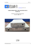
USER OPERATION AND MAINTENANCE
MANUAL
FREQUENSY METER FM-WG/70/220
Part No. FM-WG/70/220
1st edition, March 2013
Frequency meter WG/70/220
User Manual
Table of Contents.
1. Introduction.
1.1 General Description.
2. Specifications.
2.1 Common Specifications.
2.2 Mechanical. 2.2 Mechanical Specifications.
2.3 Block-diagram of the Frequency Meter.
2.4 Front panel.
2.5 Rear panel.
3. Installation.
3.1 Assembly procedure.
3.2 Put into operation.
4. Operation.
4.1 Measuring procedure.
5. GPIB interface.
5.1 Set GPIB address.
5.2 GPIB commands
Frequency meter WG/70/220
ELVA-1
User Manual
ELVA-1
1. INTRODUCTION.
This instruction manual contains information on operation of the Frequency meter
WG/70/220, hereinafter called Frequency meter.
1.1 General Description.
Frequency meter is intended for measuring frequency in range 70-220GHz.
The
Frequency
Meter
is
based
on
sweepable
heterodyne
Frequency meter WG/70/220
receiver.
User Manual
ELVA-1
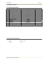
2. SPECIFICATIONS.
2.1 Common Specifications.
No.
1
2
3
4
5
6
7
8
9
10
11
12
13
14
15
Specifications
Input Frequency range
Maximum input
Minimum input
Damage level
Dynamic range
Standard Input connectors
Standard Input waveguide
Standard Output connector
Modes of operation
Accuracy
Resolution
IF Output
Control Interface
Power Supply
Operating temperature range
Range
70 – 220 GHz
+ 10 dBm
-20 dBm
+13 dBm
30 dB
Flange UG-378/U-M
WR-10
SMA
Counter +/- 1 MHz
1 kHz
50-100 MHz
GPIB
230 V, +/- 10%, 50- 60 HZ,~200 VA
+10C…+ 50C
2.2 Mechanical Specifications.
1. Size
2. Weight
Frequency meter WG/70/220
52 х 17 х 35 cm.
10,2 kg.
Remarks
User Manual
ELVA-1
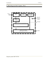
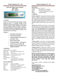
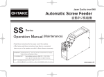
2.3 Block-diagram of the Frequency Meter.
Input
Harmonic
Mixer
Multiplier
X6
Synthesizer
12-19 GHz
External
Reference
10 MHz
LNA
1-150 MHz
IF output
Frequency Counter 1-100 MHz
Built-in PC station
with touchscreen LCD
Frequency meter WG/70/220
GPIB
User Manual
ELVA-1
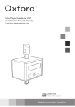
2.4 Front panel.
Disposition of the plugs and knobs on the front panel of the Radiometer are the
following:
1
1.
2.
3.
4.
5.
6.
7.
2
3
4
Power switch.
Power indicator.
Touchscreen display.
USB ports.
Tuning knob.
IF connector, BNC.
Waveguide input, UG-387/U-M, WR10.
Frequency meter WG/70/220
5
6
7
User Manual
ELVA-1
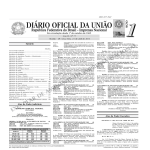
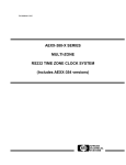
2.5 Rear panel.
Disposition of the plugs on the rear panel of the Radiometer are the following:
8
9
10
11
8. GPIB connector.
9. COM port (don’t used).
10. USB ports.
11. LAN ports
12. Keyboard and mouse connectors, PS/2.
13. Display connector.
14. Power plug 90-230V AC with power switch
Frequency meter WG/70/220
12
13
14
User Manual
ELVA-1
3. INSTALLATION.
3.1 Assembly procedure.
The Frequency Meter is fully completed device and don’t require any special
components.
3.2 Put into operation.
-
Switch off power switch (14) on the rear panel.
Connect power cable to socket (14)
Connect power cable to primary line 90-230V AC
Switch ON power switch (14) on the rear panel.
If needed install WR-10 extension waveguide, bend
For measure frequency higher > 120GHz install waveguide adapter WR-10 to WR-05
4. OPERATION.
4.1 Measuring procedure.
-
Connect DUT to input of Frequency meter. To be sure, that output power of DUT <
20mW
Switch ON power switch (1) on the front panel.
Wait for while start up procedure of built-in PC is finished.
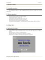
When start up procedure is done the following menu is appeared.
Frequency meter WG/70/220
User Manual
ELVA-1
-
Touch knob ‘Refresh’ and Frequency meter starts measuring procedure or press central
button of knob (5) on front panel1
-
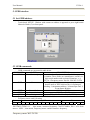
When input frequency is measured, result is displayed. Signal level indicator line shows
input power.
Frequency meter WG/70/220
User Manual
-
If any signals not found, Frequency meter scan continuously
-
To update measuring frequency touch knob ‘Refresh’.
Frequency meter WG/70/220
ELVA-1
User Manual
ELVA-1
5. GPIB interface.
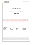
5.1 Set GPIB address.
-
Touch knob ‘SETUP’. Window with current set address is appeared or press right button
Manual of knob (5) on front panel.
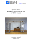
5.2 GPIB commands.
- GPIB commands are presented in table below
COMMAND
NAME
DESCRIPTION
*IDN?
Identification Query Returns its identification code as four fields separated
by commas. These fields are: manufacturer, model, sixdigit serial number and version of firmware - e.g.
ELVA-1 Frequency meter Part No. FM-WG 70-220
*RST
Reset
The Frequency meter restores its power-up state except
that the state of IEEE-488 interface is unchanged,
including: 1) instrument address, 2) Status Byte and, 3)
Event Status Register.
:STRF!
Start refresh
{SUCC} or {FAIL}
:SPRF!
Stop refresh
{SUCC} or {FAIL}
:SCRS?
Get scanning result
{RF<value>P<value>%} or {NULL}
- To get measured result command :SCRS? should be sent
- Frequency meter send 18b string
Parameter
Frequency, MHz
Pin
R
F
x
x
x
x
x
x
.
x
x
x
P
x
x
.
x
%
Example of response:
‘RF078455.576P43.1%’ , that means, measured frequency 78455.576MHz, Pin = 43% from
max or ‘NULL’, that means, Frequency meter couldn’t measure frequency.
Frequency meter WG/70/220