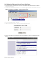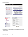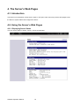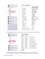
1
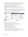
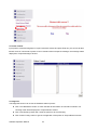
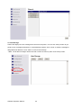
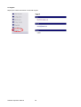
OPERATION MANUAL
GodexLAN for Wireless LAN & Ethernet Module
Operation Manual : GodexLAN
Version
: Rev. E
Issue Date
: 2012.07.12
P/N
: 920-061510-00
1. PRODUCT OVERVIEW ............................................................................ 1
1-1. General Description .......................................................................................................................... 1
1-2. Ethernet Module Specifications......................................................................................................... 2
1-3. Wireless LAN Module Specifications ................................................................................................ 3
1-4. Product CD ........................................................................................................................................ 3
2. THE CONTROL CENTER ........................................................................ 4
2-1. Get the Control Center from CD........................................................................................................ 4
2-2. Using the Control Center................................................................................................................... 4
2-3. System menu .................................................................................................................................... 5
3. NETWORK CONFIGURATION ................................................................ 6
3-1. Setting up Local Windows Printer Driver .......................................................................................... 6
3-2. Connecting the Hardware ................................................................................................................. 6
3-3. Wireless Connection ......................................................................................................................... 7
3-3-1. Preliminary .............................................................................................................................. 7
3-3-2. Set Wireless Configuration Using Network Printer Server Control Center ............................. 8
3-3-3. Set Wireless Configuration Using Server’s Web Pages ....................................................... 10
3-4. Assigning an IP Address to the Server ........................................................................................... 14
3-4-1. Preliminary ............................................................................................................................ 14
3-4-2. Setting the IP Address Using the Control Center ................................................................. 15
3-4-3. Setting the IP Address Using the Server’s Web Pages ........................................................ 17
4. THE SERVER’S WEB PAGES ............................................................... 19
4-1. Introduction...................................................................................................................................... 19
4-2. Using the Server’s Web Pages ....................................................................................................... 19
4-2-1. Displaying Server Status ...................................................................................................... 19
4-2-2. Setting up Server Configuration............................................................................................ 20
5. TROUBLESHOOTING ........................................................................... 27
5-1. Q & A ............................................................................................................................................... 27
5-2. Firewall ............................................................................................................................................ 27
6. RESTORE FACTORY DEFAULTS ........................................................ 28
7. UPGRADE SERVER FIRMWARE .......................................................... 29
1. Product Overview
1-1. General Description
Network Printer Server is designed to connect your printers to your network, allowing all network users
access to these shared printers. This Server provides the following features and benefits:
Reliability: The Server provides high performance and reliability combined with low power
consumption.
Flexibility: The Server supports print sharing in all major computer systems and environments.
Easy to Install: The Server installs, operates, and is managed in a reliable and easy fashion.
Security: You can assign administrator name and password to restrict login.
Monitoring: The Server’s web pages and user software allow you to continuously monitor the status of
connected printer devices.
Future Proof: The firmware stored in the Server’s Flash memory can be upgraded over the network.
This allows you to quickly update and enhance its operational features when new Server software
becomes available.
To fully benefit from this document, you should be familiar with basic networking principles. The instructions
described in this manual are based on the settings in a new Server. To reload the Factory Parameters, you
can reset this Server back to Factory Default, which will restore most of the settings. For details, please refer
to the chapter “Restore Factory Defaults”.
Software Operation Manual
1
1-2. Ethernet Module Specifications
ITEM
CPU
SDRAM
Flash Memory
Connector
Standard
Protocol
ETHERNET
Server
Setup
Security
Connector
USB Port
Standard
POWER
LED LAMP
ENVIRONMENT
DIMENSIONS
WEIGHT
OTHERS
Description
32-bits RDC(x86), 133 MHz
4M Bytes
2M Bytes
RJ-45 Connector
IEEE 802.3 10/100Base-Tx (Auto-Sense)
ARP, IP, UDP, TCP, HTTP, DHCP, FTP, SNMP, SMTP
TCP Server ; UDP Server
HTTP Browser Setup (IE & Netscape)
Setup Password & Connect Password
Dual row 8-pin header
USB 2.0 Host mode, Full speed 12M bps
DC 5V, 300mA
SYS(PWR) , LAN-100 MBPS, LAN –10MBPS
Operating Temp: 0℃~50℃
Storage Temp : -10℃~70℃
95 x 51.5 x 20 mm ( W x D x H )
100 gm
Watch Dog Function, Firmware On-lined Updated Via Ethernet
USB Port connector pin assignment:
Pin 1
Pin 3
Vbus
D+
Pin 2
Pin 4
GND
D-
Software Operation Manual
Pin 5
Pin 6
2
+5V
GND
Pin 7
Pin 8
+5V(RLY)
GND
1-3. Wireless LAN Module Specifications
ITEM
CPU
SDRAM
Flash Memory
Standard
Description
32-bits RDC(x86) , 133 MHz, miniPCI
16M Bytes
2M Bytes
IEEE 802.11b/g, 2.4GHz, DSSS
802.11b : 1, 2, 5.5, 11 Mbps
Data Speed
802.11g : 6, 9, 12, 18, 24, 36, 48, 54 Mbps
Network
Infrastructure, Ad-Hoc
TX Power 802.11b : ~15 dBm; 802.11g : ~12 dBm
802.11b : -80 dBm@11 Mbps, Packed Error Rate 8%
RX Sensitivity
802.11g : -65 dBm @ 54 Mbps, PER 10%
Wireless LAN
Protocol
ARP, IP, UDP, TCP, HTTP, DHCP, FTP, SNMP, SMTP
Server
TCP Server ; UDP Server
802.11b : WEP64-128bit
Security
802.11g : WPA-PSK / WPA2-PSK with TKIP/AES
Setup
HTTP Browser Setup (IE & Netscape)
Security
Setup Password & Connect Password
Connector RJ-45 Connector
Ethernet
Standard
IEEE 802.3 10/100Base-Tx (Auto-Sense)
Function
Support Wireless LAN setup configuration and Alertnative Wireless LAN
Connector Dual row 8-pin header connector
USB Port
Standard
Host mode, Full speed 12M bps
POWER
DC 5V, 500mA
LED LAMP
SYS(PWR), LAN/WLAN
Operating Temp : 0℃~45℃
ENVIRONMENT
Storage Temp : -10℃~70℃
DIMENSIONS
95 x 70 x 20 mm ( W x D x H )
WEIGHT
185 gm
OTHERS
Watch Dog Function, Firmware On-lined Updated Via Ethernet
USB Port connector pin assignment:
Pin 1
Pin 3
Vbus
D+
Pin 2
Pin 4
GND
D-
Pin 5
Pin 6
+5V
GND
Pin 7
Pin 8
+5V(RLY)
GND
1-4. Product CD
This CD provides easy-to-use Control Center software and the User’s Manual. The Control Center is
available on the CD or from official website. This Server can be configured and managed from its internal
web pages or from the Control Center. These web pages or PC tools offer you a management tool suitable
for all supported network environments.
Software Operation Manual
3
2. The Control Center
2-1. Get the Control Center from CD
1. Insert the included CD into the personal computer.
2. Go to "Control Center" folder and double click the "Setup Control Center.exe" icon to install the program
to your personal computer.
3. After the installation is completed, please click the "Control Center" icon to start the program.
2-2. Using the Control Center
You can use the following tools to help you use the server:
Refresh Server List: renew to auto search the existing servers on the network.
Go to Homepage: go to the web pages of the highlighted print server.
Configure Server: configure the highlighted printer server.
*Note 1: You can also right-click the mouse button on the highlighted print server to get the “Configure
Server” and “Go to Homepage” functions.
*Note2: You can also double-click on the highlighted server to get the “Configure Server” function.
Displaying Server Status
You can start the Control Center and click on a server to see its status which includes Printer Information,
Server Information, TCP/IP status, and Supported Protocols.
Setting up Server Configuration
Click the “Configure Server” button to setup the highlighted print server. Then type the administrator ID and
password to login.
TCP/IP: You have to set the Server’s TCP/IP configuration to connect TCP/IP network. Please see the
chapter of Network Configuration for more details.
Wireless: Set the wireless connection configurations. Please see the Wireless Connection section in
the chapter of Network Configuration for more details.
Software Operation Manual
4
2-3. System menu
System: Select the "Exit" item to close the Control Center.
Tools: Select "Configuration" item to configure the Control Center. The configuration includes server
information setting and language setting.
Help: To display the version information of Control Center.
Quitting the Control Center
There are two ways to close the Control Center. The first way is clicking the “X” box (close box) at the top
right corner of the window. The second way is choosing “Exit” item in the “System” menu in the Control
Center.
Software Operation Manual
5
3. Network Configuration
3-1. Setting up Local Windows Printer Driver
You are advised to install your Windows printer driver in advance. For most printers, you can install the
printer drivers with the following procedure:
1. Click Start, click Control Panel, click Printers and Other Hardware, and then click Printers and Faxes.
2. Double click Add Printer to start the Add Printer Wizard, and then click Next.
3. Click Local printer, clear the Automatically detect and install my Plug-n-Play printer check box to avoid
having to wait for the completion of another printer search, and then click Next. If you leave this option
selected, Windows will attempt to find the printer itself and figure out what kind it is. If Windows does not
find the printer, the wizard will continue as described in this task.
4. Select a Windows driver for your printer. Click Next.
5. Choose whether you want to share the printer with other network users. Do you want to print a test page?
Select the appropriate radio button and click Next and Finish.
3-2. Connecting the Hardware
1. Turn off the printer.
2. Connect the Ethernet module to the network with a twisted-pair category 5 cable, 10baseT or
100baseTX.
3. Turn on the printer and make sure it is ready for use.
* Note: If you need to connect the printer via LPR protocol, please go to Windows printer setting page and go
to "Ports" setting. Select TCP/IP port from ports list and click "Configure Port".
Software Operation Manual
6
On "Port Settings", change the "Protocol" to "LPR". And the "Queue Name" setting must be "USB1_LQ" to
connect your printer properly.
3-3. Wireless Connection
3-3-1. Preliminary
Before you can access wireless network, wireless parameters should be set correctly. You have to
setup the first wireless parameter set through LAN (wired) connection.
Wireless access can be set as:
1. Infrastructure (station) mode, which need an access point to route network messages, or
2. Ad-hoc mode, which connect nearby wireless PC/devices with the same SSID (Service Set ID).
Wireless access can be secured by WEP64, WEP128, or WPA-PSK / WPA2-PSK with TKIP/AES.
In infrastructure mode, if network administrator wants to change any security related parameters,
Network Printer Server should be changed first, and then access point. If parameters mismatch
causes wireless access is not allowed, you have to modify those parameters through LAN connection.
In infrastructure mode, the maximal transfer rate is 54 MBits depending on access point’s capability.
In ad-hoc mode, only 802.11b (the maximal transfer rate is 11 MBits) is allowed by specification.
Software Operation Manual
7
3-3-2. Set Wireless Configuration Using Network Printer Server Control Center
1. Install the "Control Center" program to your PC. Network Printer Server Control Center is available in the
product CD of Ethernet or Wireless LAN module.
2. Start the Network Printer Server Control Center and an Auto-searching Network Printer Server window
will appear.
*If the wireless parameters are not correct or not set yet, you have to use LAN to access Network Printer
Server.
3. If the tool finds Network Printer Servers in your local area network, then you have to select a server from
the server list.
4. Double click the highlighted server (or click the “Configure Server” button) and type the server’s
administrator (default: admin) and password (default: admin).
Software Operation Manual
8
5. After you login successfully, from the Server menu, select wireless. The set Wireless dialog appears.
6. In order to join an existing wireless network, you have to set the correct network type (infrastructure or
ad-hoc), SSID, and the correct security method with the correct key information.
*Please check with your Network Administrator about network setting if necessary.
7. If the wireless network is secured by WEP64 or WEP128, authentication method, key index, and WEP
key must be set correctly.
8. If the wireless network is secured by WPA-PSK/WPA2-PSK, the shared key must be set correctly.
Software Operation Manual
9
9. Click Apply to save your settings. And the server will reboot.
10. You have now finished the procedure of setting the wireless parameters.
*In infrastructure mode, Network Printer Server Control Center searches all channels to join the matched
wireless service set. In ad-hoc mode, Network Printer Server Control Center searches all channels to join
the matched wireless ad-hoc service set too, however, if none of them are found, Network Printer Server
Control Center creates that service set in the assigned channel.
*In ad-hoc mode, WPA-PSK/TKIP is not allowed.
3-3-3. Set Wireless Configuration Using Server’s Web Pages
1. You can see the IP address of Network Printer Server in the server list. Open IE Browser and type
server’s IP address or click the Home Icon of Network Printer Server Control Center.
*If the wireless parameters are not correct or not set yet, you have to use LAN to access Web Pages.
*If the TCP/IP parameters of Wireless LAN module are not correct, you have to use Network Printer
Server Control Center to set the TCP/IP parameters first.
2. Go to the web page and click "Login" link.
3. Login your administrator (default: admin) and password (default: admin).
Software Operation Manual
10
4. After you have logged in successfully, the first configure page will be General Configuration of printer
server.
5. To proceed the wireless configuration, click the "Configuration" icon.
Software Operation Manual
11
6. Click "WLAN" icon.
7. In order to join an existing wireless network, you have to set the correct network type (infrastructure or
ad-hoc), SSID, and the correct security method with the correct key information.
8. If the wireless network is secured by WEP64 or WEP128, key index and WEP key must be set correctly.
9. If the wireless network is secured by WPA-PSK/TKIP, the shared key must be set correctly.
Software Operation Manual
12
10. Click Submit to save your settings. And the server will reboot.
11. You have now finished the procedure of setting the wireless parameters.
*In infrastructure mode, Network Printer Server Control Center searches all channels to join the matched
wireless service set. In ad-hoc mode, Network Printer Server Control Center searches all channels to
join the matched wireless ad-hoc service set too, however, if none are found, Network Printer Server
Control Center creates that service set in the assigned channel.
*In ad-hoc mode, WPA-PSK/WPA2-PSK is not allowed.
After properly configuring the wireless parameters, you can remove the network cable and reboot the printer.
The Wireless LAN module will then connect to your wireless network. Network Printer Server Control Center
will detect if a network cable is plugged-in or not. If a network cable is plugged-in, Network Printer Server
Control Center will always connect to the network through the network cable. Otherwise it will always
connect to the network through wireless module. Once Network Printer Server connects to the network,
either by network cable or by wireless module, all operations of print server are exactly the same.
Software Operation Manual
13
3-4. Assigning an IP Address to the Server
3-4-1. Preliminary
If you have a DHCP server on your network, your Server will receive an IP address automatically. The
IP address will then appear on the Control Center or on the page of configuration report. If your DHCP
server does not give an IP address to the Server, the Server will use the Factory IP address.
If you are not working in a DHCP network, you need to manually set the Server’s IP address.
Ethernet Address
You do not need to know the Ethernet address of your Server for assigning an IP address to it. The Control
Center can automatically search Servers and list their Ethernet addresses.
IP Address
Unless you are assigning an IP address using DHCP, you must obtain an unused IP address from your
network administrator.
Methods for Setting the IP Address
You can set the IP address of your Server using one of the following methods, depending on your network
operating environment:
Automatic IP Address Assignment
Manual IP Address Assignment
Server Names and Server Name Rules
The default server name of the Server is “WLAN PrintServe/LAN PrintServer”. If you put two or more Servers
in your local area network, to avoid using the same server names you have to change the server names by
using the Control Center or the Server’s web pages. If your server name is longer than 15 characters, the
Server uses only the first 15 characters.
Software Operation Manual
14
3-4-2. Setting the IP Address Using the Control Center
1. Start the Control Center and Auto-searching Server window will appear.
2. If the tool finds print servers in your local area network, then you have to select one server from the
Server List.
3. Double click the highlight list and enter the Server’s administrator (default: admin) and password (default:
admin).
4. After you have logged in successfully, select TCP/IP from the Server’s menu. The Set IP Address dialog
appears.
Software Operation Manual
15
5. Click the button corresponding to your choice of IP setting method (static or dynamic using DHCP). When
assigning a static IP address you also have to define Subnet Mask and Default Gateway. If you choose
"Automatically get IP by DHCP", you can use desired DNS by clicking the Manual DNS button and
manually assigning a DNS.
6. Click Apply to save your settings. And the Server will reboot.
7. You have now finished the procedure of setting the IP address.
Software Operation Manual
16
3-4-3. Setting the IP Address Using the Server’s Web Pages
1. If you don’t know the current IP of you Server, you have to do the Step1~Step4 of Set the IP Address
Using the Control Center.
2. You can see the IP address of you Server in the Server List. Open IE Browser and enter the Server’s IP
address or click the “Go to Homepage” button in the Control Center.
3. Go to the web page and click "Login" link.
4. Login your administrator (default: admin) and password (default: admin).
5. After you have logged in successfully, the first configure page will be General Configuration of printer
server.
Software Operation Manual
17
6. Click the "Configuration" icon.
7. Click TCP/IP icon.
8. Click the button corresponding to your choice of IP setting methods (static or dynamic using DHCP).
When assigning a static IP address you also have to define Subnet Mask and Default Gateway.
9. Click Submit to save your settings. And the Server will reboot. You have now finished the procedure of
setting the IP address.
Software Operation Manual
18
4. The Server’s Web Pages
4-1. Introduction
The Server runs the daemon of http server, httpd on TCP port: 9100. Users may use the web pages to see
the Server’s system status and configure the Server.
4-2. Using the Server’s Web Pages
4-2-1. Displaying Server Status
You can see the status of Printer, Server, TCP/IP and Wireless.
Software Operation Manual
19
4-2-2. Setting up Server Configuration
To set up the Server configuration, the system will request user to enter administrator (default: admin) and
password (default: admin) to login.
User Accounts: You can change administrator name and password or add a user account for print
server. If you forgot administrator name and password, you must perform Restore Factory Default action.
Please refer to the chapter “Restore Factory Defaults”.
Set Administrator
New Administrator: enter your desired administrator name.
New Password: enter your desired password.
Retype Password: confirm your previous password typing.
User Accounts list
User name: add a new user account for accessing the storage attached to the Server.
Password: set a password for added user.
Add: click Add button, after entering the user name and corresponding password. The account will
take effect once shown in the blank below.
Delete: delete the existing user account.
Configuration
TCP/IP: You have to set the Server’s TCP/IP configuration to connect TCP/IP network. Please see
the chapter of Network Configuration for more details.
WLAN: Set or change the WLAN configurations. Please see the "Set Wireless Configuration Using
Server’s Web Pages" section of Network Configuration chapter for more details.
Printer Configuration: Set or change the configurations of printer. Please refer to printer's operation
manual check the function of each setting item.
Software Operation Manual
20
Alert Message Filter: Enable or disable the options to send error messages via Auto-Mail or SNMP.
SNMP: This Server runs an SNMP daemon supporting SNMP v1 and v2c protocols (Simple
Network Management Protocol). Users can use SNMP client software such as HP OpenView to
Software Operation Manual
21
manage the Server. The Server supports all relevant parts of MIB-II and a private MIB. You can set
these MIB variables from the Server’s web pages or by using the Control Center. You can set
community and some parameters for SNMP server. The SNMP Configuration includes:
Authentic Community: set Community name of SNMP server.
Trap Community: set Trap Community name for SNMP server to send trap packets.
Trap Address (IP): enter an IP address to send the Trap packet.
SysContact: enter some letters for variable of SysContact that represents the name of system
contact.
SysName: enter some letters for variable of SysName that represents the name of system.
SysLocation: enter some letters for variable of SysLocation that represents the location of system.
EnableAuthenTrap: enter 1 or 2 for the variable of EnableAuthenTrap that represents to enable (1)
or disable (2) to send Trap packets receiving the wrong Community name.
SMTP:
SMTP Protocol: enable or disable the SMTP Protocol.
SMTP Server Name: set the IP address or server name of SMTP Server.
SMTP Port Number: set the port number, the range is from 1 to 65535. Typical is 25.
Subject: set the subject of notification mail.
From Address: set the From Address of notification mail.
To Address: set the From Address of notification mail.
Cc: set the Cc receiver of notification mail.
Duration Cycle: set the cycle time to send the notification mail.
Event Counter: set the accumulation number of error messages to send the notification mail.
*Note: If Duration Cycle and Event Counter are both set together, the sending notification mail
event will be triggered depending on which conditions is fulfilled first.
Software Operation Manual
22
Maintenance
If you want to restore factory default values of the Server and upgrade new firmware of Ethernet/Wireless
LAN or printer, you can use the Maintenance tool:
Printer Firmware Upgrade: click Open to find the firmware file to be upgraded. Click Upload to
upload the firmware into the printer.
Server Factory Default: click this button, the Server will restore factory default values.
Server Firmware Upgrade: click Open to find the firmware file to be upgraded. Click Upload to
upload the firmware into the Server.
Restart Server: click this button, the Server will restart.
Software Operation Manual
23
Printer Control
Input printer's command language in "Input Command" window and press Enter key, the server will then
transfer a line of commends to printer. If sent command returns response message, the message will be
displayed in "Output Message" window.
Diagnosis
The Diagnosis function can check the hardware status of printer.
Click "TPH Resistance" button to check the bad dot information of Thermal Print Head. The
checking result will be displayed in "Output Result" window.
Click "Auto-Sensing" button will control the printer to do Auto-Sensing.
Click "Printer Config" button to get the configuration of the printer in "Output Result" window.
Software Operation Manual
24
Alert Message
Collect and display the error message that come from the printer. You can click "Dump" button to get
printer's error message and display it on Alert Message window. Click "e-mail" to send the message to
designated mail address or click "Clear" to remove the message.
*Note: The all alter messages will be removed out from the memory when click “Dump” button.
Software Operation Manual
25
Support
Display the contact information of technical support.
Software Operation Manual
26
5. Troubleshooting
This chapter provides useful information to help you resolve difficulties that you may experience with your
Server. Fault symptoms, possible causes, and remedial actions are provided within a quick reference table.
5-1. Q & A
Problem
Why the Control Center can not detect
the Ethernet/Wireless LAN module?
Why I can not use IE to set the
Ethernet/Wireless LAN module?
Why the IP address of
Ethernet/Wireless LAN module can not
be changed?
Recommended Solution
Make sure the network cable is connected correctly.
The Control Center may be blocked by firewall. Please refer
to "Firewall" section to change the firewall configuration.
Please check the module’s Gateway address is same as
the computer’s Gateway address. Both of them must be in
the same Gateway domain for setting the Ethernet module
by IE.
Please login to the control center and change the “DHCP
client” to TCP/IP.
5-2. Firewall
If a firewall software has been installed on your PC, it may block the communication between the PC and the
print server so that the print server can not work properly. To solve this problem, either disable the firewall or
configure the firewall to allow the following TCP and UDP ports:
7303, 7305, 20005, 30201, 30202, 30203
Software Operation Manual
27
6. Restore Factory Defaults
1. Go to the Server’s web page and click Login
2. Enter administrator (default: admin) and password (default: admin).
3. Click Maintenance.
4. Click Server Factory Default.
5. Click Yes to confirm
Software Operation Manual
28
7. Upgrade Server Firmware
*Note: Failure of server firmware loading or upgrading may cause damage to the Ethernet/Wireless LAN
module. Please follow below procedures for loading and upgrading firmware, or please seek help from your
network administrator.
This chapter describes how to upgrade firmware. Please follow the following procedure:
1. Power on the Server. Suppose that the Server is in DHCP mode.
2. Check the Server's IP address.
3. First, run Control Center. It will automatically search for Servers on the LAN. Then Servers’ IP addresses
will be shown in Control Center.
4. Run any Web browser, like Microsoft Internet Explorer. Go to “http://Server’s IP address“ to access the
Server's home page.
5. Click Login at the top of the menu.
6. Login the Server with Administrator (default: admin) and Password (default: admin).
7. Click Maintenance.
8. Click Server Firmware Upgrade.
9. Click Browse button to choose the file of new firmware.
10. Click Upload button to start firmware upgrade.
11. Wait for 15 seconds for system reboot.
Software Operation Manual
29