1
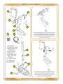
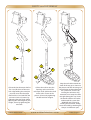
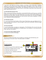
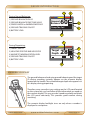
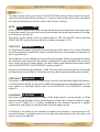
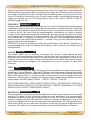
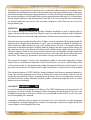
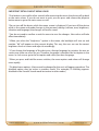
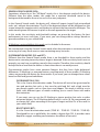
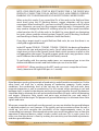
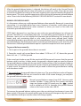
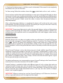
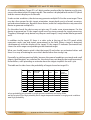
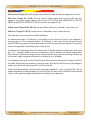
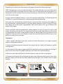
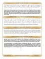
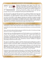
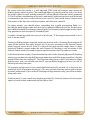
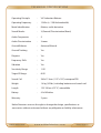
I NT RODUC T I O N
Thank you for choosing and purchasing our Nokta FORS Gold detector.
FORS Gold, developed by Nokta's expert engineering team experienced in metal
detection, is a professional metal detector designed based on gold prospectors'
needs.
Manufacturing high-tech metal detectors since 2001, Nokta Detectors has played a
key role in the development of this sector. Nokta Detectors is particularly known for
its technological know-how and professional staff.
Seeking to create different kind of technology, Nokta Detectors offers both
high-quality products and services to its consumers all around the world. Nokta
Detectors has been operating under the principle that environmental and
community responsibility, customer satisfaction and insistence on high-quality are
of the utmost importance.
Nokta Detectors aims to remain a leading pioneer in its sector, winning the trust of
its consumers and always being the preferred choice for metal detecting.
NOKTA DETECTORS
w w w.noktadetec tors.com
FORS / Page 1
TABLE OF CONT EN TS
WARNINGS ............................................................................................................................................................. 3
PARTS and ASSEMBLY .................................................................................................................. 4-5
CORRECT WAY OF HOLDING and SWEEPING ................................................ 6
BATTERIES ............................................................................................................................................................... 7
DEVICE INTRODUCTION ........................................................................................................ 8-14
CONTROLS ........................................................................................................................ 8-9
MAIN SCREEN ........................................................................................................... 9-10
NUMERIC DISPLAY ................................................................................................... 10
MENU ................................................................................................................................. 11-14
SEARCH MODES ............................................................................................................................. 15-16
GROUND BALANCE ................................................................................................................... 16-20
SENSITIVITY and THRESHOLD ........................................................................................... 21
TARGET ID and ID MASKING ...................................................................................... 22-23
PINPOINT ............................................................................................................................................................ 24
DEPTH INDICATION ............................................................................................................................ 25
SWEEP SPEED and TARGET IDENTIFICATION ........................................... 25
LARGE or SHALLOW TARGETS .......................................................................................... 25
FALSE SIGNALS and COMMON CAUSES ............................................................ 25
MAGNETIC MINERALIZATION LEVEL ....................................................................... 26
HOT ROCKS AND SEARCHING IN ROCKY AREAS ....................... 26-27
EFFECTS OF HOT ROCKS IN GROUND TRACKING ............................... 27
METALS UNDER HOT ROCKS ..................................................................................... 27-28
MESSAGES ......................................................................................................................................................... 29
FACTORY and STARTUP SETTINGS .............................................................................. 30
TECHNICAL SPECIFICATIONS .............................................................................................. 31
NOKTA DETECTORS
w w w.noktadetec tors.com
FORS / Page 2
WARNI NGS
LEGAL WARNINGS
► When using the device, comply with all applicable laws and regulations. Do not use the
device in private premises, historic sites and military zones. Notify the authorities of any
historical or cultural findings.
WARNINGS ABOUT THE DEVICE
► This is a high-tech electronic device. Do not assemble or use the device before reading
the user manual.
► Do not expose the device or the search coil to very hot or cold conditions for extended
periods of time. (Storage Temperature: 0°C (32°F) - 40°C (104°F))
► Do not immerse the device or its accessories (except the search coil) in water; do not
expose them to extreme humid conditions.
► Protect the device from external impact, especially during transportation.
IMPORTANT
IMPORTANT
► The device can only be opened and repaired by authorized service technicians. The
warranty will be voided if the device is opened by you or an unauthorized person.
Do not use the device indoors. The device
will constantly give target signals inside
places like homes where there are many
metals present. Use the device outdoors, in
open fields.
Do not let another detector or an
electromagnetic device come in close
proximity (10m (33ft.)) to the device.
Do not carry any metal objects while using
the device. Keep the device away from your
shoes while walking. The device may detect
the metals on you or inside your shoes as
targets.
For Consumers within the European Union: Do
not dispose of this equipment in general
household waste. The crossed wheeled bin
symbol on this equipment indicates this unit
should not be disposed of in general household
waste, but recycled in compliance with local
government regulations and environmental
requirements.
NOKTA DETECTORS
FCC STATEMENT
This device complies with Part 15 of the FCC Rules. Operation is subject to the
following two conditions: (1) this device may not cause harmful interference,
and (2) this device must accept any interference received, including interference that may cause undesired operation.
w w w.noktadetec tors.com
FORS / Page 3
PARTS and ASSEM B LY
1
7
7
3
4
2
Attach the right/left armrest components to the
S-rod with the bolts and nuts as seen in the
picture. Do not tighten the nuts but rather leave
them loose (these will be tightened after the
system box is attached).
BATTERY
10
BATTERY
BATTERY
BATTERY
9
1) System Box
2) Handle and S-Rod
3) Right/Left Armrest
Components
4) Armrest Strap
5) Search Coil
6) Telescopic Shaft
7) Bolts, Nuts and
Washers
8) 3 Cable Clamps
9) 4 AA Batteries
10) Headphones
6
8
7
5
7
NOKTA DETECTORS
Place the system box on the rail behind the
armrest and push forward. Then secure by
tightening the nuts. Attach the armrest strap
by inserting it through the holes.
w w w.noktadetec tors.com
FORS / Page 4
PARTS and ASSEM B LY
1
3
2
1
2
4
1)To attach the telescopic shaft to
the S-rod, first loosen the twist
lock. 2)By holding the metal pin
pressed, insert the telescopic
shaft into the S-rod and click the
pin into its hole. 3)Secure it by
tightening the twist lock. 4)After
adjusting the shaft length to your
height, secure by tightening the
twist lock.
NOKTA DETECTORS
3
1)Place the washers into the
openings at the end of the
telescopic shaft. 2)Place the shaft
on the coil as shown in the
picture. 3)Secure by tightening
the bolt and the wingnut.
w w w.noktadetec tors.com
Wrap the coil cable around the
shaft all the way up as shown in
the picture and after inserting it in
the coil input socket underneath
the system box, secure it by
twisting the connector. Pay
attention to not wrap the cable
too tight during this step. Insert
the handle cable in the socket
underneath the system box
(HANDLE) and secure it by
twisting the connector. Finally,
secure the cable by attaching the
clamps at 3 different spots.
FORS / Page 5
CORREC T WAY OF HO L D I N G
Shaft height is wrong.
Shaft height is correct.
It is very important to adjust the shaft to your
height correctly to be able to search without
discomfort and fatigue.
Adjust the height of the shaft so that you are
standing in an upright position, your arm is
relaxed and the search coil is approximately 5cm
(~2'') above the ground.
CO RR E C T WAY OF SWEEPI NG
Wrong search coil angle
Wrong search coil angle
Correct search coil angle
Incorrect way of sweeping
Correct way of sweeping
It is important to keep the search coil
parallel to the ground in order to get
accurate results.
The search coil must be parallel to the
ground at all times.
NOKTA DETECTORS
w w w.noktadetec tors.com
FORS / Page 6
BAT TERI ES
The device comes with 4 AA Alkaline batteries.
Slide and remove the battery compartment cover by pressing the latch. Insert the batteries
paying attention to the + (plus) and – (minus) poles.
When batteries are full, they will provide approximately 25-30 hours of use. Different types
or brand of batteries may have different lifetimes.
For best performance, using AA Alkaline batteries is recommended. You may also use high
quality rechargeable Ni-MH batteries. Rechargeable batteries with higher mAh (capacity)
ratings will provide longer run times. Using batteries with minimum 2500mAh is recommended.
LOW BATTERY
The battery icon on the LCD panel indicates the battery life status. In addition, a warning
message will appear on the screen when the batteries are low. After the low battery
warning, the batteries will run approximately 3-4 more hours. This runtime will vary based
on the remaining battery charge. Ni-MH batteries have lower voltage so their remaining
runtime will be longer than Alkaline batteries. This does not affect the total runtime.
ROCK
IRON
ROCK
Target
ID
GEN
45
76
General Search
NOKTA DETECTORS
IRON
Target
ID
45
--
00
76
GEN
Low Battery
General Search
w w w.noktadetec tors.com
FORS / Page 7
DE VI C E I NTRODUC TI O N
1
5
2
4
3
7
6
CO N TROL S
(1) POWER SWITCH:
To turn on the device, press the power switch to (1) position. The startup tone will be heard
and after the Nokta logo is displayed for a short period of time, the main screen will come
up on the LCD panel.
(2) GROUND TRACKING SWITCH:
When the ground tracking is active (at 1 position), the device will track the changes in
ground and automatically adjust the ground balance to suit. The invisible changes in
ground affects the detection depth as well as the discrimination ability of the device so you
can improve the performance of the device by activating this feature on suitable ground.
You can find more details about ground tracking on page 19.
(3) MENU AND SETTINGS SWITCHES:
These switches allow you to access the menu and scroll through options as well as adjust
device settings.
On the main screen, you can access the menu by pressing one of the up/down/+/switches. You can select the menu options with the up and down switch and change the
value with the + (plus) and - (minus). Pressing these switches in a specific order will result
in ''resetting factory settings'' or ''saving startup settings''. You can find more details about
this on page 30 under the title FACTORY and STARTUP SETTINGS.
NOKTA DETECTORS
w w w.noktadetec tors.com
FORS / Page 8
DE VI C E I NTRODUC TI O N
If you press and hold any of these switches at startup, system information including
software version and the serial number of the device will appear on the screen after the
Nokta logo is displayed for a few seconds. This information will stay on the screen as long
as you hold the button pressed. Please have his information ready when you contact your
dealer regarding your device.
(4) GROUND BALANCE BUTTON:
Allows you to ground balance manually or automatically before or during your search. By
keeping this button pressed and pumping the coil, you can quickly ground balance the
device at any time. When you press and release the button, you can ground balance
manually by changing the ground balance value on the screen. Please read pages 16-20 for
more information on ground balance.
(5) PINPOINT SWITCH:
It is used to find the exact location of the target. Pinpointing saves you digging time by
narrowing down the location of a buried target. Please refer to PINPOINT section on page
24 for more details.
(6) LED FLASHLIGHT:
Is used for illumination at night or in dark places. The flashlight will not work when the
device is off. Having the flashlight on will affect power consumption so we recommend to
keep it off when not needed.
(7) LED FLASHLIGHT POWER SWITCH:
Is used to turn on/off the flashlight.
MA I N S CR E E N
You can see all the information you need during searching, ground balancing, and
pinpointing on the main screen. The information is as follows:
1
During Searching:
1) TARGET ID
2) TARGET ID INDICATOR (HORIZONTAL BAR)
3) MAGNETIC MINERALIZATION LEVEL
4) GROUND TRACKING ON/OFF
5) SEARCH MODE or WARNING MESSAGE
6) BATTERY LEVEL
NOKTA DETECTORS
2
ROCK
IRON
Target
ID
GEN
w w w.noktadetec tors.com
45
76
3
4
General Search
6
5
FORS / Page 9
DE VI C E I NTRODUC TI O N
During Ground Balancing:
ROCK
1) GROUND BALANCE VALUE
2) GROUND BALANCE FINE TUNE VALUE
3) SEARCH MODE or WARNING MESSAGE
4) GROUND TRACKING ON/OFF
5) BATTERY LEVEL
1
2
60
20
IRON
Ground
Balance
Pump The Coil
4
5
3
1
During Pinpointing:
1) TARGET DEPTH
2) NEGATIVE/POSITIVE BAR INDICATOR
3) MAGNETIC MINERALIZATION LEVEL
4) GROUND TRACKING ON/OFF
5) BATTERY LEVEL
ROCK
IRON
Target
Depth
28
76
3
4
5
2
NU M E R IC DIS PL AY
The ground balance value during ground balancing and the target
ID during searching instantly appears on the numeric display
located on the handle. The estimated target depth also appears on
this display during pinpointing.
Therefore, once you adjust your settings on the LCD panel located
on the system box, you can follow all the information you need on
the numeric display. This way you don't need to go back and check
the LCD panel constantly. This provides great comfort during
searching.
The numeric display backlight turns on only when a number is
displayed to save power.
NOKTA DETECTORS
w w w.noktadetec tors.com
FORS / Page 10
DE VI C E I NTRODUC TI O N
M ENU
The menu screen allows you to access all the FORS Gold settings. You can go to the menu
screen by pressing one of the up/down/+/- switches while on the main screen and adjust
the settings of the device. Now let's take a look at these settings:
MODE: MODE
GEN
FORS Gold has 3 predefined search modes based on ground conditions and target type.
During your search, you can select one of these modes and quickly personalize its settings
in the menu if you want to.
The names of the search modes are abbreviated as GEN, DI3 and BST. Please read the
SEARCH MODES section for more details on modes (see pages 15-16).
SENSITIVITY: SENSITIVITY
50
It is the detection depth setting that controls the gain of the device. It is used to eliminate
the electromagnetic interference signals received from the surrounding environment as
well as ground noise.
Each mode has its own default sensitivity value in the menu. When you change the mode,
the sensitivity value preset for that mode is displayed. This does not affect the sensitivity
levels set by the user in other modes. For ideal settings and detailed information please
refer to the SENSITIVITY and THRESHOLD settings (page 21).
Sensitivity level can be adjusted from 1 to 99. The most ideal sensitivity level for each mode
has been preset by the factory. Sensitivity level may be changed manually when needed.
THRESHOLD: THRESHOLD
60
Threshold is used to increase the target signals and thus the detection depth of the device.
In General Search mode, it adjusts the audible level of the constant background hum. For
more details on threshold, please refer to the SENSITIVITY and THRESHOLD settings
(page 21).
ID MASKING: ID MASKING
10
When the search coil passes over a target, if the target signal is strong enough, a 2-digit
target ID will be displayed on the numeric display as well as the LCD panel. Target ID ranges
from 0 to 99. Target ID is a number produced by the detector based on a target's
conductivity and it gives you an idea about what the target may be.
ID Masking is the ability of the detector to ignore (not produce a warning tone or ID)
unwanted targets. It provides ease of use by rejecting mineralized rocks (hot rocks) and
metals such as iron and foil.
NOKTA DETECTORS
w w w.noktadetec tors.com
FORS / Page 11
DE VI C E I NTRODUC TI O N
You can customize ID Masking according to your needs. Each mode has its own default ID
Masking value in the menu. When you change the mode, the ID Masking value preset for
that mode is displayed. This does not affect the ID Masking levels set by the user in other
modes. ID Masking is not active in the General Search mode. For detailed information on
Target ID and how to use ID Masking, please refer to the section TARGET ID and ID
MASKING (pages 22-23).
03
FREQUENCY: FREQUENCY:
Changes the operating frequency of the device. It is used to eliminate the electromagnetic
interference received from the surrounding environment or another detector operating
within the same frequency range. If the device receives a lot of noise when the search coil
is held in the air, the cause may be electromagnetic interference or a high sensitivity
setting. If you suspect electromagnetic interference, you may change the frequency. There
are 5 frequencies in the device. The factory default is 03. Normally, the frequency setting is
not enabled and it is grayed out in the menu. To activate it, while holding the pinpoint
button pressed, press one of the up/down/+/- switches. Then, you can select the frequency
option in the menu and change it.
IMPORTANT! Frequency shifting may affect the performance of the device. Therefore, it is
recommended that you do not change the frequency unless necessary and keep it at the
factory default.
02
VOLUME: VOLUME
This control allows you to increase or decrease the device's volume based on your
preference and environmental conditions. Volume level can be adjusted from 0 to 20.
When you turn off and on the device, it will start with the last volume level you chose. This
setting is common to all modes; changes will take effect in all modes. Because the volume
level affects power consumption, we recommend you not to increase it more than
necessary.
TONE: TONE:
04
It allows you to change the audio frequency of the threshold and target warning tones
according to your preference. There are 5 different audio frequencies ranging from treble
to bass. Tone change does not affect the iron tone. It is active in the General Search and
Boost (BST) modes only. It is inactive in the Discrimination 3 mode. It changes the audio
frequency of the threshold sound in the General Search mode and the gold/non-ferrous
metal sound in the BST mode (TONE 01 - TONE 02 - TONE 03 - TONE 05).
NOTE: YOUR DEVICE WILL START IN BOOST MODE TONE 4. THE DEVICE WILL PRODUCE A
SINGLE TONE FOR ALL METALS (GOLD, NON-FERROUS, FERROUS) ENABLING YOU TO HEAR
SMALLER GOLD NUGGET SIGNALS MORE CLEARLY.
08
BRIGHTNESS: BRIGHTNESS
This control allows you to adjust the backlight level of the numeric display on the handle
and the LCD panel on the system box based on your preference and environmental
conditions. Brightness level can be adjusted from 0 to 20. This setting is common to both
displays; changes will take effect on both. When you change the brightness level in the
menu, the backlight will turn on the numeric display and number ''88'' will appear for easy
adjustment. When you turn off and on the device, it will start with the last brightness level
you chose. This setting is common to all modes; changes will take effect in all modes.
NOKTA DETECTORS
w w w.noktadetec tors.com
FORS / Page 12
DE VI C E I NTRODUC TI O N
The brightness level of the LCD panel on the system box affects power consumption a lot.
Therefore, the backlight illuminates during menu access and ground balancing. It does not
illuminate during searching or target detection. On the other hand, the brightness level of
the numeric display on the handle affects power consumption relatively less. It illuminates
during target detection and pinpointing. Especially if you are using the menu frequently,
we recommend that you choose the minimum brightness level that you can see in for
longer battery life.
VIBRATION: VIBRATION
02
This feature enables the device to provide vibration feedback as well as audio when a
target is detected during searching. Vibration can be used alone without audio feedback.
When the volume is turned off, target detection will be conveyed to the user by vibration.
Vibration level can be adjusted from 0 to 5. When set to 0, vibration will be deactivated. By
adjusting the vibration level between 1 and 5, you can change the speed of vibration, in
other words the effect felt by the user, in all search modes. At level 1, the device will only
vibrate on more definite targets (shallow) and the target's vibration signal will be longer. At
the maximum level 5, the device will vibrate with smaller target signals (deeper) and the
vibration signals will be shorter. The speed of vibration will vary based on target depth and
sweep speed. When you turn off and on the device, it will start with the last vibration level
you chose. This setting is common to all modes; changes will take effect in all modes.
The speed of vibration is fixed in the pinpointing mode; it cannot be adjusted. In other
words, there is no difference between 1 and 5. But when it is set to 0, it will be off just like
in the search modes. In the pinpointing mode, the speed of vibration will increase as you
get closer to the center of target response and it will reach its maximum level at the center.
The vibration feature of FORS Gold has been developed with hearing impaired people in
mind. The hearing impaired users have to follow the screen constantly and this can be
tough during searching. There is a good chance that they will miss a target when they are
not looking at the screen. Vibration feature enables the hearing impaired users to metal
detect more conveniently.
EN
LANGUAGE: LANGUAGE
Is used to change the language of the device. The FORS Gold menus can be viewed in 10
languages. At initial startup, the factory default language will be displayed. The user can
change the language in the menu. When you turn off and on the device, it will start with
the last language you selected.
Language is placed as the last option in the menu so it is easy to find in case the language
is changed to a foreign language by mistake. For languages written from right to left, the
screen layout is also designed that way.
NOKTA DETECTORS
w w w.noktadetec tors.com
FORS / Page 13
DE VI C E I NTRODUC TI O N
IMPORTANT DETAILS ABOUT MENU USAGE:
*If no button is pressed for a few seconds after accessing the menu, the device will go back
to the main screen. If you do not want to wait, you can press and release the pinpoint
button once to go to the main screen as well.
*Do not turn off the device while the menu screen is displayed. If you turn off the device
while in the menu and made changes in the personal settings (volume, tone, brightness,
vibration and language) the changes will not be saved.
* You do not need to confirm or exit the menu to save the changes. New values will take
effect immediately.
* When you select the ''brightness'' option in the menu, the backlight will turn on and
number ''88'' will appear on the numeric display. This way, the user can see the correct
brightness level on screen and adjust it accordingly.
* If you change the language of the device to a foreign language by mistake, the text on
screen may make no sense for you. Therefore, language is placed as the last option in the
menu. In such a case, go to the last option and select your own language.
* When you press and hold the menu switches, the menu options and values will change
more rapidly.
* Disabled menu options ( that cannot be changed by the user) will appear grayed out. The
disabled option may be active in another mode. (For example; ID Masking appears
disabled in the General Search mode but active in other modes)
NOKTA DETECTORS
w w w.noktadetec tors.com
FORS / Page 14
SEARC H MODE S
GENERAL SEARCH MODE (GEN):
Sometimes referred to as the ''All Metal'' mode, this is the deepest mode of the device.
Different than the other modes, this mode has a constant threshold sound in the
background that enables the user to use his/her own judgment.
In the General Search mode, the device will detect all targets (metal, high mineralized
rocks etc.) without discrimination. The ID of the detected target will be displayed on the
screen (except for negative rocks) and the device will emit the same tone for all targets. The
audio warning tone will increase in pitch as the coil approaches the target.
In this mode, the sensitivity and threshold settings are preset by the factory for best
performance on most soil types. If you want, you can change these settings based on
ground conditions in your search field.
ID Masking is not available in this mode so it is disabled in the menu.
We recommend using the General Search mode when discrimination is not necessary and
not using it in heavy trash areas or areas containing many hot rocks.
DISCRIMINATION MODES (DI3 and BST):
Different than the General Search mode, there is no threshold in these modes and the
device emits a warning tone only when a target is detected. If the sensitivity level is not set
properly, you can hear a crackling sound in these modes. Therefore, the sensitivity should
be adjusted to a level that the device is silent when there is no metal present.
Discrimination modes have some common features but they have slight behavioral
differences. ID Masking is a common feature, used frequently in these modes. ID Masking
values are preset by the factory for these modes. If you want, you can change these values
based on field and ground conditions.
DISCRIMINATION 3 (DI3):
This is the 3-tone discrimination mode. The device will emit a low grunt tone for
iron and positive hot rocks, a low tone for gold and foil, and a high tone for
non-ferrous metals such as silver, brass and copper. This mode is ideal to use in
fields with different types of metals enabling you to search faster with audio
discrimination.
If you want, you can use the ID Masking to ignore positive hot rocks or other
unwanted targets. The ID Masking default value is set to 10. We recommend you
to change this value according to the type of target and the IDs of the rocks in
your search field.
BOOST MODE (BST):
It is the 2-tone discrimination mode (TONE 01 - TONE 02 - TONE 03 - TONE 05).
Developed for use in gold fields, this mode is deeper than DI3. It provides more
depth for nugget searching and minimizes the effects of hot rocks.
NOKTA DETECTORS
w w w.noktadetec tors.com
FORS / Page 15
SEARC H MODE S
NOTE: YOUR DEVICE WILL START IN BOOST MODE TONE 4. THE DEVICE WILL
PRODUCE A SINGLE TONE FOR ALL METALS (GOLD, NON-FERROUS, FERROUS)
ENABLING YOU TO HEAR SMALLER GOLD NUGGET SIGNALS MORE CLEARLY.
When using this mode, if you record the IDs of the rocks in the field and then
mask them using the ID Masking feature, nugget detection will be more
convenient. When masking IDs, you must use the ID value closest to the ID of the
rocks. Otherwise, you may miss the nuggets under the rocks. Consequently, you
may need to change the default ID masking value(10) of this mode to another
value based on the IDs of the rocks in the field. For more details on eliminating
hot rocks, please read the related sections Target ID and ID Masking, Hot Rocks
and Searching in Rocky Areas, and Metals Under Hot Rocks).
If you dig a target signal in a gold field and find rocks, be sure that there is no
small gold nugget underneath.
In the BST mode (TONE 01 - TONE 02 - TONE 03 - TONE 05), the device will produce
a low tone for iron and positive hot rocks. For all other metals, it will produce a
single tone just like in the General Search Mode, which increases in pitch as the
coil approaches the target. The gold nuggets under rocks may generate a tone
and ID different from that of gold and this totally normal.
To get familiar with the warning audio tones, we recommend you to test the
device with different metals and rocks before you use it in the field.
IMPORTANT! When searching in the BST mode, you must sweep the coil more
slowly (about one full right & left pass in 1 second).
GROUND BAL AN CE
Metal detectors work on the principle of conductivity and all metals are conductive. On the
other hand, soil itself has a certain degree of conductive property. Under certain
conditions, the conductivity level of the soil may be very high. Soil and rocks have
magnetic properties as well as conductivity. For this reason, when searching in soil and
between rocks, in order for the detector not to give a target signal for the soil, the detector
should be able to eliminate the soil and minimize the effects of rocks while still detecting
real targets. Otherwise, false signals and noise may mislead the user and make it
impossible to find the target. The purpose of ground balancing is to eliminate these false
signals and noise.
When you sweep the search coil over the ground, you can see whether the ground balance
is adjusted properly or not. However, if the signals and noise continue when the coil is
raised up, you must consider the possibility of the electromagnetic waves in the
surrounding environment. Electromagnetic waves may result from power lines or from the
operation of electrical devices, radars, wireless radios, and even TVs. In such a case, first
make sure that the device is silent by making the sensitivity and threshold adjustments
and then ground balance.
NOKTA DETECTORS
w w w.noktadetec tors.com
FORS / Page 16
GROUND BAL AN CE
One of the following may happen as a result of improper ground balancing:
-The device gives a signal when the coil is swept over the ground where there is no target.
-The device is silent but loses detection depth for certain metals.
-The device receives target-like signals next to holes and dips.
The above mentioned situations do not only occur as a result of improper ground balance
adjustment. However, before looking into other reasons you must be sure that the ground
balance is correctly adjusted.
Ground balance value is common to all modes; changes will take effect in all modes. When
using the automatic ground balance or ground tracking, this setting is adjusted
automatically.
Ground balance can be done in three ways in FORS Gold: Automatic, Manual or Ground
Tracking.
During automatic or manual ground balancing, when you press the ground balance
button, no matter what mode you are using, the device will unnoticeably revert to the
General Search mode and the audible tones will be heard accordingly.
AUTOMATIC GROUND BALANCE:
Automatic ground balance is done the same way in all modes:
1. Find a spot on the ground where there is no metal.
2. Press and hold the ground balance button and pump the search coil up and down from
about 15-20 cm (~6''- 8'') above the ground down to 3 cm (~1'') off the ground.
3. Continue until you hear the beep indicating that the ground balancing is completed.
Based on ground conditions, it usually takes about 1-4 pumps for the ground balance to be
completed.
4. Once the ground balance is done, the ground balance value will appear on the LCD
panel as well as the numeric display on the handle. If you continue to press and hold the
ground balance button, the device will keep on ground balancing and beeping. To make
sure that the ground balance adjustment is correct, please repeat the process 2 or 3 times
and each time check the value on the display. The difference between the values should
not be greater than 1 or 2 numbers.
5. If you cannot ground balance, meaning you don't hear the beep, either the ground is
very conductive or not mineralized or there must be a buried metal object underneath the
coil. In such a case, move to another location and re-ground balance. If you still cannot
succeed, try manual ground balancing.
90
Ground
Balance
90
90
Pump The Coil
NOKTA DETECTORS
w w w.noktadetec tors.com
FORS / Page 17
GROUND BAL AN CE
After the ground balance button is released, the device will work in the General Search
mode and the ground balance value will remain on screen for a while. (If you do not want
to wait for this period you can go to the main screen by pressing and releasing the pinpoint
button once). This gives you the opportunity of fine tuning the automatic ground balance
value. Please refer to the following MANUAL GROUND BALANCE section for more details.
MANUAL GROUND BALANCE:
It is the process where you set the ground balance value manually. Because it is more time
consuming, it is not preferred by most users. However, it becomes useful when ground
balance cannot be achieved by other methods or when you need to fine tune the
automatic ground balance value.
FORS Gold is designed in a way that you can easily auto ground balance it on all types of
ground. Therefore, we recommend that you use automatic ground balance at start up.
However, some soils are not suitable for automatic ground balancing. For example; wet
beach sand, soils containing alkali or salty water, trashy areas, plowed lands, highly
mineralized ground or ground with very low mineralization are not suitable for automatic
ground balancing. We recommend you to manually ground balance in such areas for your
convenience. Manual ground balance requires experience acquired with some practice.
To ground balance manually:
1. Find a spot on the ground where there is no metal.
2. Pump the search coil up and down from about 15-20 cm (~6''- 8'') above the ground
down to 3 cm (~1'') off the ground.
If the sound gets louder as you lift the search coil off the ground, it means that the ground
balance value is too low. In other words, the ground is negative and you need to increase
the ground balance setting with the up switch. On the contrary, if the sound gets louder as
you lower the search coil to the ground, it means that the ground balance value is too high.
In other words, the ground is positive and you need to lower the ground balance setting
with the down switch.
3. Press and release the ground balance button once. The ground balance value will appear
on the LCD panel and will stay on screen for a while. If the screen changes, you can press
the ground balance button again.
Ground
Balance
60
Pump The Coil
20
Manual ground balance ranges from 0-99. However each
number includes 5 steps used for fine tuning and these
steps are shown on the LCD panel over the
symbol
and in multiples of 20. For example; the ground balance
value on the screen to the side is 60.20.
To increase the ground balance setting, press the up switch and to decrease it, press the
down switch. If you press the switch one by one, the values will change one by one as well.
If you hold the switch pressed, the values will change rapidly.
NOKTA DETECTORS
w w w.noktadetec tors.com
FORS / Page 18
GROUND BAL AN CE
4. Continue the above process until the sound is eliminated. If the sound is not completely
eliminated, then you can fine tune.
For fine tuning, follow the numbers above the
symbol and use the + and - switches.
The sound may not be eliminated completely on some types of ground although you have
fine tuned. In such a case, to determine whether you have successfully ground balanced or
not, listen to the audio feedback when lowering the search coil to the ground and when
lifting it off the ground. If both sound the same, it means that the ground balance is
adjusted properly.
After a while the ground balance is completed, the device will switch to the main screen
automatically. If you do not want to wait for this period you can go to the main screen by
pressing and releasing the pinpoint button once.
IMPORTANT! Experienced detectorists adjust the ground balance setting to little positive
response (when lowering the search coil a weak but an audible response is heard). This
method may result in positive results in some gold fields with small nuggets when used by
experienced users.
GROUND TRACKING:
With this feature, the user does not need to make any adjustments. Ground Tracking can
be activated by turning the Ground Tracking switch to 1 position. The Ground Tracking
icon (
) on the LCD panel starts blinking. As long as the search coil is swept over the
ground, the device updates the ground balance setting. It does not provide the user any
kind of feedback ( such as the ground balance value or the beep sound in the auto ground
balance).
When Ground Tracking is active, the device may emit a loud audible signal if the ground
conditions change (for example a hot rock) or if a target is encountered. In such a case,
sweep the search coil a few times over the spot where you receive the signal. If the sound
continues and the device gives an ID, there is a high chance that it is a target. If the sound
gets weaker or disappears after a few sweeps, it means that that the device gave a signal
for the ground change or the hot rocks.
For better performance, we recommend you to use Ground Tracking in the General Search
mode and not in the discrimination (DI3 and BST) modes.
Ground Tracking is suitable for fields with different types of soils or where hot rocks are
scattered around a large area and not condensed. If you use Ground Tracking in areas
where hot rocks are intensely present (such as some gold fields), the device may not be
able to eliminate these high mineralized rocks or you may miss the smaller or deeper
metals (such as gold nuggets).
IMPORTANT! When air testing, be sure that Ground Tracking is off. Otherwise, the device
will try to ground balance over the target and lose depth.
NOKTA DETECTORS
w w w.noktadetec tors.com
FORS / Page 19
GROUND BAL AN CE
GROUND BALANCE VALUE:
The ground balance value indicates the type of ground. Some typical ground types are as
follows:
0-25
25-50
50-70
70-90
Wet salt water or wet alkali soils
Wet salt water and wet alkali soils covered with dry layers
Regular, low-quality soils
Highly magnetic soils, magnetite or maghemite and similar highly mineralized
soils, black sand
IMPORTANT DETAILS ABOUT GROUND BALANCE:
When the device is turned on, the ground balance value is preset to 90. Automatic ground
balancing value ranges from 40-90 in all modes. If the ground mineralization is too low, the
automatic ground balance may not work. In this case, if the ground effect can be felt in the
General Search mode, manual ground balancing can work. If the ground effect cannot be
felt, you can set it to 60.
You can test the accuracy of the ground balance setting in the pinpointing mode as well.
Once the ground balance is done, lower the search coil to the ground. If the device receives
no signal or a very weak one as the search coil approaches the ground, it means that the
ground balancing was successful. On the contrary, if the device receives noise as the search
coil approaches the ground, it means that the ground balance has failed. In this case,
change your location and try re-ground balancing. If you still cannot ground balance, you
need to continue searching without ground balance. Turn off and on the device again and
start searching without ground balancing. If you receive noise when you sweep the coil
over the ground, set the search mode to DI3 or BST (adjust sensitivity accordingly) and
increase the ID Masking to a level where the noise is eliminated. On the other hand,
because the ID Masking is not active in the General Search, if you cannot reduce the noise,
you cannot continue searching either.
Once the ground balance is set, it will remain satisfactory for a long time in most areas.
However, in areas where the soil has been disturbed by digging or filling up, or in
geologically complex areas -commonly encountered in gold fields- you may have to
ground balance frequently to accommodate changing ground conditions.
NOKTA DETECTORS
w w w.noktadetec tors.com
FORS / Page 20
SENSI T I VI T Y and THR ES HO L D
Adjusting these two settings correctly is critical for the device to work at its best
performance and without noise. It is possible to obtain an average performance with the
startup settings. However, to be able to have better detection depth in clean areas or to be
able to search in tough ground conditions, these two settings must be adjusted properly.
Sensitivity and Threshold in General Search Mode:
In the General Search mode, a constant background hum is heard during searching. The
loudness of this hum directly impacts the detection depth of smaller and deeper targets
and it is adjusted by the threshold setting. If the threshold is set too high, the target signal
may not be heard. On the contrary, if it is too low, you give up the depth advantage this
setting offers. In other words, weak signals of smaller or deeper targets may be missed.
Threshold setting comes with the default value at each startup (not with the last adjusted
value). It is recommended for average users to leave this setting at its default value and for
experienced users to adjust to the highest level where they can still hear the weak target
signals.
In the General Search mode, although the sensitivity setting seems like it is behaving
similarly to the threshold, it actually causes an increase or decrease in the popping sounds
and false signals. It is important to set the sensitivity setting to the highest level possible
where no major popping sounds are heard. For example; if the noise level is suitable for
searching and is the same at sensitivity levels 20 and 50, then 50 should be preferred. Using
the factory default levels will be a good starting point until you get familiar and
experienced with the device.
If the device is stable but too noisy, the threshold setting should be decreased. However, if
it sounds erratic and there is too much popping, the sensitivity setting should be lowered.
Sensitivity in Discrimination Modes:
Because there is no threshold in discrimination modes, by using the sensitivity setting
alone, you can increase the detection depth or enable the device to run without noise in
different fields.
To adjust the sensitivity setting in discrimination modes, ground balance first with the
sensitivity set at its default value. After the ground balance is completed, hold the search
coil still or sweep above the ground at the search height. If the device receives noise, lower
the sensitivity. If the device receives no noise (when checking this, please be sure that the
ID Masking is also at its factory default value), you can increase the sensitivity setting
gradually to the highest level where there are no popping sounds. During searching, if the
device starts receiving noise, lower sensitivity gradually.
NOKTA DETECTORS
w w w.noktadetec tors.com
FORS / Page 21
TARGE T I D and I D MAS KI N G
As mentioned before, Target ID is a 2-digit number produced by the detector and it gives
you an idea about what the target may be. The number is displayed both on the LCD panel
and the numeric display on the handle.
Under certain conditions, the device may generate multiple IDs for the same target. There
may be a few reasons for this: target orientation, target depth, purity of metal, corrosion,
ground mineralization etc. Based on these factors, even the sweep direction may cause the
device to generate multiple IDs.
On the other hand, the device may not give any ID under some circumstances. For the
device to generate an ID, the target signal must be strong enough for signal processing.
Therefore, although it may detect very deep or small targets, it may not be able to generate
an ID.
In addition to the target ID, there is a color scale at the top of the LCD panel which
represents rocks, iron and metals encountered in the field. When a target is detected,
simultaneously with the display of the target ID, the target ID indicator (horizontal bar)
shows the color range corresponding to the detected target.
What you should keep in mind is that the target ID and colors are estimated values and
there is no way of knowing for sure what’s buried other than to dig it up.
Especially in gold prospecting fields, because the ground conditions are tough and small
targets (gold nuggets) are searched for, the device may not identify the target accurately.
Nevertheless, even providing an estimate about the target simplifies the user's job.
The table on the side shows the probability of targets based on target IDs:
ID
0-5
5-10
10-20
20-40
40-70
70-80
80-90
90-99
Hot
Rocks
●●●
●●
●
●
Gold under
hot rocks
●
●
●●
●●●
●
Iron
●●
●●●
Gold
Silver
Brass
Copper
Aluminum
●
●●
●●●
●
●●●
●●
●
●●
●●●
● Low probability but possible in tough ground conditions and rocky fields.
●● Not its typical ID but high probability due to target shape and orientation in tough ground conditions.
●●● High probability.
NOKTA DETECTORS
w w w.noktadetec tors.com
FORS / Page 22
TARGE T I D and I D MAS KI N G
ROCK
IRON
Brown Area (Target ID: 0-16): Highly mineralized soil and positive or negative hot rocks.
Blue Area (Target ID: 16-40): Ferrous metals (Gold under rocks can also fall into this
category. For more details, please refer to the HOT ROCKS and SEARCHING IN ROCKY
AREAS and METALS UNDER HOT ROCKS sections on page 26-28).
Yellow Area (Target ID:40-70): Mostly gold, folio, soda cans, pull-tabs, some coins etc.
Red Area (Target ID:70-99): Copper, brass, aluminum, silver, some coins etc.
This data may vary based on the field conditions.
As mentioned before, ID Masking is the ability of the device to ignore (not produce a
warning tone or ID) unwanted targets. ID Masking is not active in the General Search
mode. ID Masking values of the discrimination modes are preset by the factory. If you want,
you can change the ID Masking values in the menu.
To change the ID Masking value, first choose the ID Masking option in the menu and using
the + or - switches, either increase or decrease it to the number you have determined.
Please keep in mind that certain metals, other than the ones you are masking, will also be
lost or their signal strength will diminish resulting in loss of depth.
For example; when you set the ID Masking to 40, the device will ignore all signals with IDs
less than 40 and will not produce a warning tone. The device will also miss gold nuggets
under rocks of which the received IDs are less than 40.
To give another example, in the case of receiving multiple IDs - let's say 35 and 55 - due to
target orientation or metal property, if you mask the IDs up to 40, 35 will fall in the masked
range so the signal strength may diminish and depth may decrease.
NOKTA DETECTORS
w w w.noktadetec tors.com
FORS / Page 23
PI NPOI NT
Pinpointing is to determine the center or the exact location of a detected target.
FORS Gold operates on the principle of motion. This means that you must move the search
coil over the target or the target over the search coil, in order for the device to detect it. In
the pinpoint mode, however, the device constantly gives signal when you hold the search
coil still over the target.
A proper ground balance setting is a must for accurate pinpointing. In changing ground
conditions, re-ground balancing is recommended before pinpointing.
When you press and hold the pinpoint button, a horizontal bar moving in the negative or
positive direction, indicating metal or soil/rock effects, appears on the LCD panel. The bar
starts filling up as the target is approached. The furthest point it fills up to indicates the
center of the target.
At the same time, the estimated depth reading appears on the LCD panel as well as the
numeric display on the handle. The signal tone increases in pitch and volume as the search
coil approaches the target. In the pinpoint mode, the device does not discriminate or give
target IDs. If the device is in the vibration mode, the speed of vibration will increase as you
get closer to the center of target.
To pinpoint:
1. After a target is detected, move the search coil aside where there is no target response
and press the pinpoint button.
2. Keeping the button pressed, approach the target with the search coil keeping it parallel
to the ground.
3. As the center of the target is approached, the signal tone will get stronger and change in
pitch. At the same time, the depth reading on the screen will start decreasing.
4. Mark the spot where you get the loudest response with your foot or an object.
5. Change your direction 90º and repeat the above steps. Repeating this process from a few
different angles will narrow the field of detection and give you a better idea of target
location.
Target
Depth
NOKTA DETECTORS
12
37
w w w.noktadetec tors.com
12
FORS / Page 24
DEP TH I NDI C ATI O N
The device gives an estimated depth reading based on signal strength in the pinpoint
mode. When the pinpoint button is pressed and the target is approached, the depth
reading will appear in ''cm.'' on the LCD panel and the numeric display simultaneously.
Approximate depth is provided based on the assumption that the target is a typical
modern coin. The real depth will vary based on target size. The device will give a greater
depth reading for smaller targets and for larger targets, the depth reading will be smaller
than they really are. In fact, pinpointing is used for target location and not depth
indication. Therefore, we suggest that you use the depth reading for judging the proximity
of the target.
S WE EP SP EED and TARGE T I D EN TI FI C ATI O N
FORS Gold is a very fast responding detector. When you detect a target with the FORS
Gold, in order to get an accurate ID of the target, instead of narrowing the sweeps and
making quick sweeps over the target like in other detectors, you should make wider and
deliberate sweeps. If the sweep speed is wrong, the device cannot identify the target
accurately and the IDs may bounce around. In addition, when you are sweeping the search
coil, pay attention not to tilt it up or down and always keep it parallel to the ground.
L ARGE or SHALLOW TARGE TS
Shallow targets may give multiple responses to the device. If you suspect a shallow target,
lift the search coil and sweep slowly until you get a single response. Similarly, large targets
may cause an overload in the search coil and the device may give an alarm sounding like a
siren. At the same time ''Overload'' message will appear on the LCD panel. In such a
situation, raise the search coil until the message disappears.
FALSE SI GNALS and COMM O N C AUS ES
Sometimes the device may receive signals although there is no real target. There are a few
different causes for this. Most common ones are ground mineralization or hot rocks,
electromagnetic interference in the surrounding environment, operation of another
detector nearby, rusty iron and corroded foil, and sensitivity and threshold set too high.
The electromagnetic interference can be eliminated by reducing sensitivity. If another
detector is working nearby, you can change your location and continue your search. For
ground mineralization or hot rocks, and sensitivity and threshold set too high, please read
the related sections. (Ground Balance, Hot Rocks and Searching In Rocky Areas, Metals
Under Hot Rocks, Sensitivity and Threshold).
NOKTA DETECTORS
w w w.noktadetec tors.com
FORS / Page 25
MAGNE T I C MI NER ALI Z ATI O N L E V EL
Magnetic Mineralization level ranges from 0-99 and is
76 displayed in the Magnetic Mineralization Indicator on the
Target
right side of the main screen. This measurement can be
ID
summarized as the amount of the magnetic property and
intensity of the ground. Simply, if you are working on a
GEN General Search
ground with intense and magnetic minerals, this value will
be high. If the ground has low magnetic intensity, this value will be small.
45
This measurement is important from two aspects. First, detection depth is low in areas with
high magnetic mineralization and the user should be aware of this fact. Magnetic
mineralization is very high especially in ''black sand'' where ''magnetic iron oxides'' (these
are not iron, their effect is in the opposite direction) are abundant. As experienced gold
prospectors know, the possibility of finding gold in black sand is high. Therefore, very high
values of magnetic mineralization may indicate the presence of gold. Second, magnetic
mineralization is a property also found in hot rocks and measuring its level will play an
important role for the device to eliminate false signals caused by hot rocks.
HOT ROC K S and SEARC HI NG I N RO CKY AREAS
Tough ground conditions occur especially if the conductivity and magnetic properties of
the ground are intense. Most of the time, correct operation of the device on such ground
is possible with accurate mode selection, proper ground balance, sensitivity and threshold
settings.
Stones and rocks or dips and holes in the ground affect the quality of searching and target
detection as much as the ground itself does.
Soil and rocks have two different properties just like the targets you are searching for. One
of them is the intensity and the other one is the conductivity - magnetic permeability ratio
and these two properties are independent from each other. In this manual, the
conductivity - magnetic permeability ratio will be referred to as ID in short. High magnetic
permeability, low conductivity results in low ID. Soil or rocks can be highly permeable and
have low or high IDs as well. If the conductivity increases relatively to magnetic
permeability then the ID will also increase.
Hot rocks are classified as negative or positive based on their ID being low or high in
comparison to the ID of the soil they are in. One or both of the types may be present in a
field. The negative and positive effects mentioned here will only be valid if ground
balancing is properly done on the existing ground. Otherwise, soil itself will not act
differently from hot rocks in terms of ID. In ''Ground Tracking'' however, conditions will
differ. Therefore, the effects of hot rocks in ''Ground Tracking'' will be discussed separately.
Here we are referring to a proper ground balance without ''Ground Tracking''.
Positive hot rocks act and sound just like metals. In the General Search mode, when you
sweep the search coil over them, they tend to give a short ''zip zip'' sound. If the signal is
strong enough, the device may also give an ID for these rocks. Negative hot rocks, on the
other hand, tend to give a longer ''boing'' sound when the search coil is swept over them.
The device will not give an ID for these rocks regardless of the signal strength.
NOKTA DETECTORS
w w w.noktadetec tors.com
FORS / Page 26
HOT ROC K S and SEARC HI NG I N RO CKY AREAS
In discrimination modes, positive hot rocks will give a typical metal sound again. Negative
hot rocks will not give any sound in these modes (except for occasional false signals).
Therefore, while searching in the field, you can decide by listening to the warning tones
emitted by the device. If you get a metal tone, it means that you have either detected a
metal or a positive hot rock. If you get a strong signal and a stable ID, you can determine
whether it is a hot rock or a metal by looking at the ID. Please keep in mind though weaker
signals tend to give different IDs and metals under rocks may produce different metal
signals. Consequently, digging up a target signal is the best option.
Because you can encounter such a situation in gold prospecting areas where nuggets are
being searched for, it is important for you to get familiar with the hot rocks and their IDs in
your search field and pre-test the device with some nuggets.
If you are using the discrimination modes and know the IDs of the hot rocks around you, you
can use ID masking to eliminate these rocks. However, this may not be sufficient to avoid all
rock signals. The device may still receive signals from rocks because soil and hot rocks
together will form a combined effect and generate a different ID than those of rocks.
E F F E C TS OF HOT ROC K S I N GRO UN D TR ACKI N G
When the ground tracking is active, the device may give a warning tone and ID when it
passes over a hot rock because the effect of the hot rock will be different than the
ground's. If you sweep the search coil over the rock, ground tracking will automatically
adjust the setting and the warning tone/ID will either disappear or diminish significantly.
Because there is a slight delay in ground tracking, you may hear a strong signal at the first
one or two sweeps until the setting is adjusted. Then the sound will get weaker and
disappear. This will not happen with metal targets because metals will prevent the device
from ground balancing. Therefore, in ground tracking, if you are getting a constant signal
over a target after repeated sweeps, there is a high possibility that the target is a metal.
Moving from over a hot rock back to soil, the device may give signals to the ground for a
few sweeps until the ground balance setting is updated again. This is normal and should
not mislead you.
Under normal circumstances, ground tracking should not be used for elimination of hot
rocks. It is recommended for use in areas with changing soil types.
ME TALS UNDER HOT RO CKS
In principle, there are two reasons for the presence of a metal under a hot rock. The first one is
easy to guess if you are in a frequently searched area. It is a hard task for average or simple
detectors to find metals under rocks. These detectors will generally miss the metals and thus
make them available for you and protected from others. For this reason, a missed target by
another detector makes you lucky for reading this manual and using the FORS Gold.
The other reason is a geological one and is a commonly encountered situation in gold
prospecting fields. There has been a correlation between the formation of hot rocks and the
formation of gold underneath or around them within the millions of years geological process.
This fact really increases the possibility of the presence of gold under hot rocks.
NOKTA DETECTORS
w w w.noktadetec tors.com
FORS / Page 27
ME TALS UNDER HOT RO CKS
No matter what the reason is, a well adjusted FORS Gold will increase your chance of
finding metals under hot rocks. The combined effect of a metal and a hot rock is less than
the metal's effect by itself and the received ID will be different than the metal's expected
ID. The ID will be a combination of the rock's and metal's and based on how small the metal
is compared to the rock, it will be closer to the rock's ID. You should always keep in mind
that metals under hot rocks will never appear with their own metal ID.
For these reasons, you should always remember that in gold prospecting fields, it is
possible for gold signals under hot rocks to be reflected differently and for the device to
give a different metal ID and tone instead of gold. For example; a gold nugget under a brick
may generate an iron tone and ID instead of gold.
In reality a simple principle can save you a lot of time: ''If the target encountered is not a
rock, it can be metal''.
The key to finding targets especially under positive hot rocks is knowing the maximum ID
value of the positive hot rocks around you. If you are searching in the General Search
mode, keep an eye on the ID. If the ID is close to the rock and iron range, there is a high
chance of finding a target under the rock. Because ID Masking is not an option in the
General Search mode, you need to ignore signals based on the ID number on screen.
In the discrimination modes, if you eliminate hot rocks with a properly adjusted ID Masking
setting, you can hear the signal of the target under the rock if the target signal has a slightly
greater effect than the masked ID. The important thing here is that if you detect a target
and dig out a rock, you should note the ID you got before digging and use it as the ID
Masking value the next time.
For example; the hot rocks in your search field tend to give IDs around 3-4. In this case, you
should set the ID Masking to maximum 5. This way you can eliminate rocks and the signals
of metals underneath. If you set the ID Masking too high unnecessarily, you will lose metals
along with rocks.
If the hot rocks in your search area tend to give high IDs, then the chances of missing the
signals of small metals underneath will be high as well.
NOKTA DETECTORS
w w w.noktadetec tors.com
FORS / Page 28
MESSAGES
At the bottom of the LCD panel, on the main screen, messages will appear if any. If there is
no message, the present search mode name will be displayed. Messages that may appear
are as follows:
OVERLOAD:
It appears simultaneously with the overload warning alarm sounding like a siren. This
happens when the search coil encounters a shallow or a very large object. The device will
revert back to normal operation if you lift the coil up. If the alarm and the message
continues along a long line, you may be over a long metal such as a pipe.
PUMP THE COIL:
It appears when the ground balance button is held pressed for automatic ground
balancing. It does not indicate any issues or errors. It just tells you what to do.
COIL NOT CONNECTED:
It indicates an interruption in the search coil transmitter signal. The search coil connector
may be unattached, loose or disconnected. If you own another detector with the same coil
connector, please be sure that you have not attached the wrong coil by mistake. If none of
the above exists, the search coil or its cable may have a defect. If the issue continues when
you change the search coil, there may be an issue in the coil control circuit.
LOW BATTERY:
This message appears when the battery level drops below a certain point. The device may
continue to work a few more hours. Meanwhile, please change the batteries.
NOKTA DETECTORS
w w w.noktadetec tors.com
FORS / Page 29
FAC TORY and STARTUP S E T TI N GS
The technical settings of the device (Mode, Ground Balance, Sensitivity, Threshold, and ID
Masking, Frequency) come with their factory default values at each startup. Personal
settings (Volume, Tone, Vibration, Brightness, and Language) come with the last adjusted
value when the device is turned off and on again.
You can customize and save your startup settings by following the steps below:
1. Go to the menu screen and be sure that all the options are at the desired setting.
2. Wait and exit the menu.
3. On the main screen, press and hold one of the up or down switches for at least 4 seconds.
The menu screen will appear; do not let go of the switch!
4. Keeping the switch pressed, press the '-' (minus) button. ''Please wait'' message will
appear on screen. You can let go of the switches.
5. Wait while the message is on screen. In about 4-6 seconds, the process will finish and the
menu screen will come up. It is normal for the device to emit different sounds during this
process.
6. Turn off and on the device again. Go to the menu to check whether your desired startup
settings are saved or not.
Changing the startup settings do not mean changing the factory default settings. You can
restore factory defaults at any time. This process is done the same way. The only difference
is that you use the '+' switch instead of '-'
1. Be sure that you have exited the menu and you are in the main screen.
2. On the main screen, press and hold one of the up or down switches for at least 4 seconds.
The menu screen will appear; do not let go of the switch!
3. Keeping the switch pressed, press the '+' (plus) switch. ''Please wait'' message will appear
on screen. You can let go of the switches.
4. Wait while the message is on screen. In about 4-6 seconds, the process will finish and the
menu screen will come up. It is normal for the device to emit different sounds during this
process.
5. Turn off and on the device again. Go to the menu and be sure that the factory defaults
are restored.
NOKTA DETECTORS
w w w.noktadetec tors.com
FORS / Page 30
T EC HNI C AL SP EC I FI C ATI O N S
Operating Principle
:
VLF Induction Balance
Operating Frequency
:
15 Khz (+/- 100 Hz bandwidth)
Metal Identification
:
Motion, multi-derivative
Search Modes
:
3 (General/Discrimination/Boost)
Audio Frequencies
:
5
Audio Discrimination
:
3 tones
Ground Balance
:
Auto and Manual
Ground Tracking
:
Yes
Pinpoint
:
Yes
Frequency Shift
:
Yes
Vibration
:
Yes
Sensitivity Range
:
1-99
Target ID Range
:
0-99
Search Coil
:
28.5x17.8 cm (11.2’’x 7.0’’) waterproof DD
Weight
:
1.8 kg (3.9 lbs.) including batteries and search coil
Length
:
125-150 cm (4'2''-5') extendable
Battery
:
4 AA Alkaline
Warranty
2 years
Nokta Detectors reserves the right to change the design, specifications or
accessories without notice and without any obligation or liability whatsoever.
NOKTA DETECTORS
w w w.noktadetec tors.com
FORS / Page 31