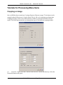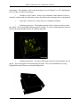
1
Media Cybernetics, Inc. Manual and Tutorials
MEDIA
CYBERNETICS, INC.
User Manual
Version X2
From Images to Answers
March, 2008
Page 1
Media Cybernetics, Inc. Manual and Tutorials
MEDIA
CYBERNETICS, INC.
User Manual
Version X2
From Images to Answers
March, 2008
Page 2
Media Cybernetics, Inc.
Limitation of Liability ............................................................. 7
Limitation of Liability Notice ..........................................................................................7
Copyright Notice ..............................................................................................................8
Software License Agreement ...........................................................................................8
Installation, Transferring a License, Uninstalling, and Hardware Requirements .............................................................. 13
Sales Information ............................................................................................................13
Technical Support ...........................................................................................................13
Software and Hardware Requirements - Windows Systems ..........................................13
Software Installation .......................................................................................................14
Dongle Installation and Requesting a Permanent License .............................................14
Updating the Dongle ..............................................................................................15
Starting the AutoDeblur Software - Windows Systems .................................................15
AutoUpdate .....................................................................................................................15
Uninstalling the Software ...............................................................................................15
How to Use This Manual ...................................................... 17
Guidelines for Collecting 3D Image Datasets .................... 18
Overview ........................................................................................................................18
Optics Alignment ............................................................................................................18
Collecting Optical Sections ............................................................................................19
Setting the Top and Bottom of the Sample, and of the Scan .................................19
Setting the Top and Bottom of the Scan ................................................................20
Setting the Exposure, Gain and Offset ...........................................................................21
Cooled CCD Cameras ............................................................................................21
RS-170 Cameras ....................................................................................................23
Performing the Axial Scan .....................................................................................26
Avoiding Backlash and Hysteresis ........................................................................28
Collecting Bias and Flatfield Frames .............................................................................28
Cooled CCD Cameras ............................................................................................28
RS-170 Cameras ....................................................................................................29
Spatial Calibration ..........................................................................................................31
Vibration Control ...................................................................................................33
Collecting Confocal Datasets .........................................................................................34
Sampling Issues ......................................................................................................35
Confocal Aperture ..................................................................................................36
2-Photon Dataset Collection ...........................................................................................38
March, 2008
Page 1
Media Cybernetics, Inc.
Guide for Obtaining the Correct Collection Parameters ........................................38
Introduction .......................................................................... 39
What is 3D Deconvolution ............................................................................................39
Application of the AutoDeblur Deconvolution Package ................................................42
What is Blind Deconvolution? .......................................................................................44
Important Features of AutoDeblur .................................................................................45
Basic Principles Underlying the AutoDeblur System ....................................................46
User Interface ....................................................................... 47
Using the Interface .........................................................................................................51
Using the Data Manager ........................................................................................51
Using the Data Properties Dialog ...........................................................................52
Using the Image Enhancement Tool ..............................................................................52
Status Display .................................................................................................................53
Using the Dataset Window .............................................................................................54
Zooming a Dataset .................................................................................................54
Selecting a Projection .............................................................................................54
Selecting a Single View .........................................................................................54
Creating a Region of Interest .................................................................................55
Saving and Copying the Current View ..................................................................55
Linking Slice Viewers ............................................................................................56
Tutorials for File Menu Items .............................................. 57
Opening a Dataset ...........................................................................................................57
Saving a Dataset .............................................................................................................58
Guidelines for naming your file(s): ........................................................................58
Save As ..................................................................................................................58
Saving the Application Layout .......................................................................................59
Editing the User Options ................................................................................................60
Exiting AutoDeblur/AutoVisualize ................................................................................60
Recent Files List .............................................................................................................61
Exporting Data ................................................................................................................61
Export to Image-Pro ...............................................................................................61
Export to Imaris .....................................................................................................61
Export to MetaMorph .............................................................................................61
March, 2008
Page 2
Media Cybernetics, Inc.
Tutorials for the View Menu Items ...................................... 62
Displaying the Data Browser ..........................................................................................62
Displaying the Status Dialog ..........................................................................................62
Displaying the Task Batch ..............................................................................................62
Displaying a Dataset .......................................................................................................64
Using the Max, Min and Sum Projections ......................................................................64
Using the Slice Viewer ...................................................................................................64
Synchronizing Slice Viewers .................................................................................65
Scrolling through Slices .........................................................................................65
Adding and removing Datasets from Slice Synchronization .................................65
Selecting a Single View ..................................................................................................65
Triple View .....................................................................................................................66
Saving the View .............................................................................................................67
Copying the View ...........................................................................................................67
Tutorials for Processing Menu Items ................................. 68
Cropping an Image .........................................................................................................68
Extending Slices .............................................................................................................70
Resizing an Image ..........................................................................................................70
Performing CCD Correction ...........................................................................................72
Slow Scan Cooled CCD .........................................................................................72
High Speed CCD ....................................................................................................74
Correcting Attenuation ...................................................................................................75
Equalizing the Background ............................................................................................75
Subtracting the Background ...................................................................................76
Correcting Optical Density .............................................................................................77
Aligning an Image ..........................................................................................................79
Slice to Slice ...........................................................................................................79
Channel to Channel ................................................................................................82
Inverting Image Data .....................................................................................................83
Image Algebra ................................................................................................................83
Tutorials for Deconvolution Menu Items ............................ 85
Performing 3D Deconvolution .......................................................................................85
Performing 2D Deconvolution .......................................................................................87
Using the Inverse Filter ..................................................................................................89
Using the Nearest Neighbor/No Neighbor Algorithms ..................................................89
To Process the Current Slice ..................................................................................90
To Process a Stack .................................................................................................91
Performing DIC Restoration ...........................................................................................91
March, 2008
Page 3
Media Cybernetics, Inc.
Restoration Method ................................................................................................91
Explaining the DIC Image Settings .......................................................................91
Expert Settings ................................................................................................................92
2D Blind Deconvolution (Interactive) ............................................................................97
Real Time Deblur ...........................................................................................................99
Tutorials for Analysis Menu Options ................................ 101
Counting and Tracking .................................................................................................101
Track Selected Objects .........................................................................................101
Preprocessing .......................................................................................................102
Histogram .............................................................................................................102
Statistics Frame ....................................................................................................102
Export Objects/Export Segmented Data ..............................................................102
Statistics ........................................................................................................................102
Please close all views before going on to the next section. ..........................................103
Measurement ................................................................................................................103
Line Length ..........................................................................................................103
Using the FRET Module ..............................................................................................104
Correcting FRET Cross Talk ...............................................................................104
Calculate FRET Efficiency ..................................................................................107
Use Cross Talk Coefficients Tutorial ...................................................................109
Calculate FRET Efficiency Tutorial ....................................................................109
Ratiometrics ..................................................................................................................110
Images ..................................................................................................................110
PreProcessing .......................................................................................................110
Use Grynkiewicz Equation for Ion Concentration ...............................................110
PostProcessing .....................................................................................................112
Colocalization ...............................................................................................................113
Image 1/Image 2 ...................................................................................................113
Colocalization Preview ........................................................................................114
2D Histogram .......................................................................................................114
Operations ............................................................................................................115
Colocalization Statistics .......................................................................................115
Delete ...................................................................................................................115
Save Statistics ......................................................................................................115
Generate Coloc Image ..........................................................................................116
Close .....................................................................................................................116
Help ......................................................................................................................116
5D Viewer Documentation ................................................. 118
Introduction ..................................................................................................................118
Requirements ................................................................................................................118
March, 2008
Page 4
Media Cybernetics, Inc.
Interface Overview .......................................................................................................118
Toolbar .........................................................................................................................119
Tutorial: ........................................................................................................................120
Time series ....................................................................................................................120
Object Parameters .........................................................................................................121
Tutorial: ........................................................................................................................122
Navigation ....................................................................................................................122
Keyboard Hotkeys ................................................................................................123
Image Display Controls ................................................................................................123
Coloring ...............................................................................................................123
Volume Rendering ........................................................................................................124
Isosurface ......................................................................................................................127
Ortho slices ...................................................................................................................128
Oblique slices ...............................................................................................................129
Region of interest .........................................................................................................130
Scalebar ................................................................................................................130
Axis ......................................................................................................................130
Grid ......................................................................................................................130
Camera .................................................................................................................131
Scene ....................................................................................................................131
Movie Making ..............................................................................................................132
Windows .............................................................................. 133
Cascade .........................................................................................................................133
Tile Vertically ...............................................................................................................133
Tile Horizontally ..........................................................................................................133
Close All Images .........................................................................................................133
Close All Modules ........................................................................................................133
Show Dock Windows ...................................................................................................133
Hide Dock Windows ....................................................................................................133
Window List .................................................................................................................134
Help .................................................................................... 135
AutoDeBlur/AutoVisualize Help .................................................................................135
Check for Updates ........................................................................................................135
About ...........................................................................................................................135
Frequently Asked Questions ............................................. 136
March, 2008
Page 5
Media Cybernetics, Inc.
Appendices ......................................................................... 140
Table of Z Spacings (Z Step Sizes) ..............................................................................140
Table of Parameters ......................................................................................................141
Toolbar Icons ................................................................................................................142
File Toolbar Icons ................................................................................................142
Visualization Toolbar Icons .................................................................................143
View Toolbar Icons ..............................................................................................143
Analysis Toolbar Icons ........................................................................................144
Statistics Toolbar Icons ........................................................................................144
Zoom Toolbar Icon ..............................................................................................144
Bibliography ....................................................................... 145
Customer Feedback ........................................................... 150
Index
March, 2008
Page 6
Media Cybernetics, Inc. Manual & Tutorials
Limitation of Liability
Limitation of Liability Notice
To the maximum extent permitted by applicable law, Media Cybernetics Inc. disclaims all warranties, either expressed or implied, including, but not limited to implied warranties of merchantability and fitness for a particular purpose with respect to the AutoDeblur/AutoVisualize software
package, the accompanying written materials, and any accompanying hardware. Specifically, the
software is not guaranteed to work on every 3D microscopy image, even if it is of a type that the
software is stated to be intended for in this manual.
Information furnished by Media Cybernetics Inc., in this manual is believed to be accurate and
reliable; however, Media Cybernetics Inc. assumes no responsibility for its use; nor for any
infringements of patents or other rights of third parties, which may result from its use.
No license is granted by implication or otherwise under any patent rights of Media Cybernetics
Inc.
Media Cybernetics Inc. shall not be liable in any event for incidental or consequential damages in
connection with, or arising out of the use of, the furnishing, performance, or use of this documentation, the AutoDeblur/AutoVisualize software or any additional software provided for use with
the software.
To the maximum extent permitted by applicable law, in no event shall Media Cybernetics Inc., or
its dealers be liable for any damages whatsoever (including, without limitation, damages for loss
of business profits, business interruption, academic prestige, academic funding, loss of business
information, or any pecuniary or other loss) arising from the use or inability to use this Media
Cybernetics Inc.. product, even if Media Cybernetics, Inc. has been advised of the possibility of
such damages. Because some states/jurisdictions do not allow the exclusion or limitation of liability for consequential or incidental damages, the above limitation may not apply to you. (In the
event that Media Cybernetics is liable under implied warranty or incidental damages, the period is
limited to one year from date of purchase).
This notice will be governed by and interpreted in accordance with the laws of the State of Maryland in the United States of America.
March, 2008
Page 7
Media Cybernetics, Inc. Manual & Tutorials
Copyright Notice
© Copyright 1995 – 2007 by Media Cybernetics Inc.
MANUAL: All rights reserved. This manual may not be reproduced, stored in a retrieval system,
or transmitted, in any form, by any means, electronic, mechanical, by photocopying, recording, or
otherwise, in whole or in part, without the written permission of Media Cybernetics, Inc.
SOFTWARE: United States copyright laws and international treaty provisions protect the
AutoDeblur software package. It is illegal to copy the software except as specifically allowed in
the License Agreement stated below. Any person found storing or using an unlicensed copy of
this software is liable to be sued by Media Cybernetics, Inc. to the maximum extent permissible
under applicable US and International laws and International Treaty Provisions.
Software License Agreement
This is a legal agreement between you (either an individual or an entity), the end user and Licensee, and Media Cybernetics Inc. (“Media” or we), the Licensor. BY OPENING THE SEALED
MEDIA PACKAGE or by installing this software on a computer, YOU ARE AGREEING TO BE
BOUND BY THE TERMS OF THIS AGREEMENT. By doing so, the user is acknowledging that
he/she has carefully read and considered all the provisions of this Software License Agreement
and agrees they are fair and reasonably required to protect Media’s interests. The end user thereby
agrees to all of the terms spelled out in this Agreement. IF YOU DO NOT AGREE TO THE
TERMS OF THIS AGREEMENT, RETURN THE UNOPENED MEDIA PACKAGE AND THE
ACCOMPANYING DOCUMENTS TO Media. The following information is important and
should be treated as valuable property. Please save the following information for future use.
1.
GRANT OF LICENSE: Subject to the terms of this Software License Agreement, Media
Cybernetics Inc., Inc. (“Media”) hereby grants to a single user Licensee non-transferable (except
as expressly provided in Section 4 below) and non-exclusive license to use and execute the AutoQuant software (“SOFTWARE”) on a single computer or facility (“COMPUTER”) at any time
during the period of validity of this license. This software may only run on one computer. If you
have a multiple-user license, the SOFTWARE may be run simultaneously by no more persons
than the number of users licensed.
2.
COPYING RESTRICTIONS: In order to affect your license rights granted in Section 1
above, you may install the SOFTWARE by copying it onto the hard disk drive of one computer.
You may make a full or partial backup or archival copy of the SOFTWARE for your own use, or
use at the facility to which the SOFTWARE is licensed. You AGREE that: (i) your use and possession of such copies shall be solely under the terms and conditions of this Agreement, and (ii)
you shall place the same proprietary and copyright notices and legends on all such copies as
March, 2008
Page 8
Media Cybernetics, Inc. Manual & Tutorials
included by Media on the media containing the authorized copy of the SOFTWARE originally
provided by Media. You may not copy or provide copies of the SOFTWARE, in whole or in part,
to any other party.
3.
SOFTWARE USE RESTRICTIONS: (a) Reverse engineering and tampering: You may
not reverse engineer, de-compile, modify, translate, or disassemble the SOFTWARE. Any tampering with the license protection system, such as the license protection key that attaches to your
printer parallel port, or of the SOFTWARE is not permitted. Violators will be prosecuted to the
maximum extent permitted by applicable laws. (b) Not a Medical Device: This software is not
intended for usage as a Medical Device. The definition of a Medical Device appears in section
201(h) of the FD&C Act. A Medical Device is “an instrument, apparatus, implement, machine,
contrivance, or other related article, including a component, part, or accessory, which is: (i) recognized in the official National Formulary, or the United States Pharmacopoeia, or any supplement
to them, (ii) intended for use in the diagnosis of disease or other conditions, or in the cure, mitigation, treatment, or prevention of disease, in man or other animals, or (iii) intended to affect the
structure or any function of the body of man or other animals, and which does not achieve any of
its primary intended purposes through chemical action within or on the body of man or other animals and which is not dependent upon being metabolized for the achievement of any of its primary intended purposes…”. (c) Usage with Confocal Microscopes: This software may be used for
visualizing or analyzing datasets from a confocal optical microscope so long as that confocal
microscope is licensed in conjunction with U.S. Patent No. Re. 34,214. Most confocal microscope
manufacturers have such a license. It is the responsibility of the customer to determine if their
confocal microscope is licensed in conjunction with U.S. Patent No. Re. 34,214, which may be
done by enquiring with their confocal microscope manufacturer. This software may not be used
with confocal microscopes that do not have such a license. Media Cybernetics will not be responsible for any infringement nor appearance of such infringement. This restriction does not in any
way imply any acknowledgment by Media of the validity of U.S. Patent No. Re. 34,214.
4.
OWNERSHIP OF SOFTWARE AND MEDIA: You agree and acknowledge that Media
transfers no ownership interest in the SOFTWARE or in any SOFTWARE copy, to you under this
Agreement or otherwise, and that Media and its licensors reserve all rights not expressly granted
to you hereunder. After you pay the applicable license fee and /or purchase price for the SOFTWARE, you will own the media on which the SOFTWARE was originally provided to you hereunder and on which you subsequently copy the SOFTWARE (duly exercising the restrictions
noted in Section 2 above). Media and its licensors shall retain ownership of all SOFTWARE and
copies of the SOFTWARE or portions thereof embodied in or on such media, including owner-
March, 2008
Page 9
Media Cybernetics, Inc. Manual & Tutorials
shipof all copyrights, mask work rights, patents, trademarks, trade secrets and all other intellectual property rights subsisting in the SOFTWARE, documentation, enhancements, adaptations
and any modifications thereto.
5.
TRANSFER RESTRICTIONS: You may not distribute, rent, sell, sublicense or lease or
otherwise transfer the SOFTWARE without express written permission from an authorized Media
official.
6.
ENFORCEMENT OF TERMS, TERMINATION: If you fail to fulfill any of your
material obligations under this Agreement, Media and/or its licensors may pursue all available
legal remedies to enforce this Agreement, and Media may, at any time after your default of this
Agreement, terminate this Agreement and all licenses and rights granted to you under this Agreement. You agree that if Media terminates this Agreement for your default, you will, within thirty
(30) days after any such termination, deliver to Media all software provided to you hereunder and
copies thereof embodied in any medium.
7.
GOVERNING LAWS: This Agreement will be governed by and interpreted in accordance to the laws of the State of Maryland in the United States of America.
8.
LIMITATION OF LIABILITY NOTICE: THE SOFTWARE IS PROVIDED ON AN
"AS IS" BASIS, WITHOUT ANY OTHER WARRANTIES OR CONDITIONS, EXPRESSED
OR IMPLIED, INCLUDING, BUT NOT LIMITED TO, WARRANTIES OF MERCHANTABLE
QUALITY, SATISFACTORY QUALITY, MERCHANTABILITY OR FITNESS FOR A PARTICULAR PURPOSE, OR THOSE ARISING BY LAW, STATUTE, USAGE OF TRADE,
COURSE OF DEALING OR OTHERWISE. SPECIFICALLY, THE SOFTWARE IS NOT
GUARANTEED TO WORK TO SATISFACTION ON EVERY 3D MICROSCOPY IMAGE,
EVEN IF THE IMAGE IS OF A TYPE THAT THE SOFTWARE IS STATED TO BE
INTENDED FOR. THE ENTIRE RISK AS TO THE RESULTS AND PERFORMANCE OF
THE SOFTWARE IS ASSUMED BY YOU. NEITHER Media, OUR DEALERS, REPRESENTATIVES, LICENSORS OR SUPPLIERS SHALL HAVE ANY LIABILITY TO YOU OR ANY
OTHER PERSON OR ENTITY FOR ANY INDIRECT, INCIDENTAL, SPECIAL OR ECONOMIC LOSS, EVEN IF WE HAVE BEEN ADVISED OF THE POSSIBILITY OF SUCH
DAMAGES, OR THEY ARE FORESEEABLE. WE ARE ALSO NOT RESPONSIBLE FOR
CLAIMS BY A THIRD PARTY. OUR MAXIMUM AGGREGATE LIABILITY TO YOU AND
THAT OF OUR DEALERS, SUPPLIERS AND LICENSORS SHALL NOT EXCEED THE
AMOUNT PAID BY YOU FOR THE PRODUCT. THE LIMITATIONS IN THIS SECTION
SHALL APPLY WHETHER OR NOT THE ALLEGED BREACH OR DEFAULT IS A
BREACH OF A FUNDAMENTAL CONDITION OR TERM OF A FUNDAMENTAL
March, 2008
Page 10
Media Cybernetics, Inc. Manual & Tutorials
BREACH. SOME STATES/COUNTRIES DO NOT ALLOW THE EXCLUSION OR LIMITATION OF LIABILITY FOR CONSEQUENTIAL OR INCIDENTAL DAMAGES, SO THE
ABOVE LIMITATION MAY NOT APPLY TO YOU.
Information furnished by Media, in the SOFTWARE manual is believed to be accurate and reliable. However, no responsibility is assumed by Media for its use; nor for any infringements of
intellectual property rights or other rights of third parties that may result from its use.
No license is granted by implication or otherwise under any patent rights of Media.
9.
CHOICE OF LAW: This notice will be governed by and interpreted in accordance with
the laws of the State of Maryland in The United States of America.
10.
US GOVERNMENT RESTRICTED RIGHTS: Use, duplication, or disclosure by the
US Government is subject to restrictions as set forth in subparagraph (c)(1)(ii) of the Rights in
Technical Data and Computer Software clause at DFARS 252.227-7013 or subparagraphs (c)(1)
and (2) of the Commercial Computer Software - Restricted Rights at 48 CFR 52.227-19, as applicable. Manufacturer of this SOFTWARE is Media Cybernetics Inc., 4340 East-West Highway, Ste
400, Bethesda, MD 20814.
11.
COPYRIGHT NOTICE: © Copyright 2003-2007 by Media Cybernetics Inc., Inc.
The SOFTWARE package is protected by United States copyright laws and international treaty
provisions. It is illegal to copy the software except as specifically allowed in this Software
License Agreement. Any person found storing or using an unlicensed copy of this software is liable to Media to the maximum extent permissible under applicable US and International laws and
International Treaty Provisions.
Should you have any questions to this Agreement, please contact Media Cybernetics Inc. 4340
East-West Highway, Ste 400, Bethesda, MD 20814. 301-495-3305.
12.
TERM: This Software License Agreement shall remain in effect only for so long as you
are in compliance with the terms and conditions of this Agreement. This Agreement will terminate if you fail to comply with any of its terms or conditions. You AGREE, upon termination, to
destroy all copies of the SOFTWARE.
13.
GENERAL: This Software License Agreement is the entire agreement between us, superseding any other agreement or discussions, oral or written, and may not be changed except by a
signed agreement. If any provision of this Software License Agreement is declared by a Court of
competent jurisdiction to be invalid, illegal, or unenforceable, such a provision shall be severed
from the Software License Agreement and the other provisions shall remain in full force and
effect.
14.
WARRANTY: Media offers a 90-day warranty of the software product. For this 90-day
period the software may be returned by the end-user to the representative for reasonable cause,
and must be returned with all product materials included in the shipping, including the software
media (e.g., CD), manual (if shipped), hardware key and any other product materials shipped. The
March, 2008
Page 11
Media Cybernetics, Inc. Manual & Tutorials
complete set of product materials must be returned for the 90-day warranty to be valid and for a
refund to be entitled. The 90-day period begins on the day of shipment of the software to the end
user from the Representative or from Media, whoever ships the product to the end user. No return
or refund is entitled after the 90-day period has expired. Upon such a valid return, the dealer is
obligated to refund the price of the product less shipping costs. The Representative will return the
product materials to Media and Media will refund the discounted price of the product, less shipping costs, to the Representative.
March, 2008
Page 12
Media Cybernetics, Inc. Manual & Tutorials
Installation, Transferring a License, Uninstalling, and
Hardware Requirements
Sales Information
Media Cybernetics Inc.
4340 East-West Highway, Ste 400
Bethesda, MD 20184
E-mail: [email protected]
Website: www.mediacy.com
Ph.: 301-495-3305
Fax: 301-495-5964
Technical Support
Internet: [email protected]
Ph.: 301-495-3305 x3
Fax: 301-495-5964
Software and Hardware Requirements - Windows Systems
Windows 2000/XP (XP is recommended). 1GB RAM, minimum (2GB RDRAM, PC800 or faster
recommended). 1GB free disk space (10GB recommended (for image storage)). A minimum of
an Intel Pentium 4 processor 2GHz processor or better. A minimum screen resolution of
1024x768 (1280x1024 recommended). A 24-bit SVGA display. CD-ROM drive.
Larger memory sizes are recommended for improved performance, keeping in mind that the operating system, the window interface and potential tasks of other concurrent tasks make strong
demands on memory resources.
The sample 3D images that are supplied with the software require approximately 350MB of disk
storage. It is recommended that due to the inherently large size of 3D images, the images be
stored on large volume expandable media such as CD-ROMs, rewritable CDs or DVDs. For routine use, a disk drive of capacity 2GB or larger is recommended.
The Volume Projection - Hardware selection in the 5D Viewer requires a video card which supports OpenGL extensions. It is recommended that an ATI Radeon 9600 series or higher be used
for the 3D Visualization. Following is an non-inclusive list of consumer level video cards which
support OpenGL coding:
March, 2008
Page 13
Media Cybernetics, Inc. Manual & Tutorials
-ATI Radeon 8500, 9000, 9700
-Diamond FireGL1
-nVidia GeForce 256, GeForce 2, GeForce 2 MX, GeForce 3, GeForce 4, all Quadro lines
-3D Labs Oxygen GVX1 and Wildcat family
-Matrox Parhelia
Software Installation
Note: Installing AQX on Windows Vista from a guest account is not supported. Install from an
account with Administrator priviledges.
To install complete the following procedure:
(1)
Unplug all USB dongles, then insert the software CD-ROM into your CD-ROM drive.
(2)
If the software asks if you want to install Microsft .NET framework 2.0, select Yes. If it
does not ask this, it is because it is already installed on the computer.
(3)
Follow the Installation Wizard’s onscreen prompts to install AutoDeblur/AutoVisualize X.
(4)
When the Installation Wizard states that AutoDeblur/AutoVisualize X has been installed,
click Finish.
(5)
A series of HASP device driver dialogs will pop up informing you that it is uninstalling
and reinstalling HASP drivers. Click OK through them. This will ensure that the dongle drivers
are up to date.
(6)
Plug in the USB dongle and wait for Microsoft Windows to notify you that the new hardware is ready to use.
(8)
Double click the AutoQuant X2 icon on the desktop or in the Start menu.
Note: If AutoQuant X2 does not automatically start the Installation Wizard, browse to the CDROM drive and double click setup.bat.
You can find the installed folder by looking in the following directories: C:\Program Files\MediaCybernetics\AutoQuant X2 .
Dongle Installation and Requesting a Permanent License
All Media products will run for one month following their initial installation on your computer.
During this time you will need to contact Media for a permanent license so that you can continue
using your software beyond the initial trial period. Once you have purchased a permanent license,
you will receive a CD and dongle, at which point you can follow the instructions below.
March, 2008
Page 14
Media Cybernetics, Inc. Manual & Tutorials
Updating the Dongle
If you have purchased additional functionality, or an extension to your maintenance or license
agreement, you will need to update your dongle to reflect the changes in you license.
(1)
Click Start->Programs->Media Cybernetics->AutoQuant X2->Dongle Update.
(2)
You will be presented with the dongle update screen.
(3)
Contact Media Cybernetics Inc., Provide the User Registration ID and Dongle ID shown
in the Dongle Update Utility dialog.
•
By Email: [email protected]
•
By phone: 301-495-3305
(4)
If the change that must be made has been approved, you will receive an update code in the
form of a long string of letters and numbers. Enter this string into the Dongle Update Code text
box and click Update Dongle.
(5)
Upon successful update, you will receive confirmation, and the update will take effect the
next time you run your AutoDeblur product.
Starting the AutoDeblur Software - Windows Systems
To start:
(1)
Choose the Start button at the lower left-hand corner of your screen and select Programs.
(2)
In the Media Cybernetics Folder, select the name of the application (either AutoDeblur or
AutoVisualize).
AutoUpdate
Media’s products incorporate an AutoUpdate feature, which will once a month connect to the
internet to search for product updates automatically. If you wish to search for an update without
waiting for the default time to pass, you can select Search for Update from the Help menu. See the
Help chapter for more information on the AutoUpdate feature.
Uninstalling the Software
Go to Add/Remove Programs under the Control Panel of your Operating System. The Add/
Remove Programs box will list all currently installed programs. Find and click on the name of the
program you wish to remove. Once the name of the program you want to remove is highlighted,
click on the Change/Remove button. The InstallShield Wizard will remove the program from your
computer.
March, 2008
Page 15
Media Cybernetics, Inc. Manual & Tutorials
March, 2008
Page 16
Media Cybernetics, Inc. Manual & Tutorials
How to Use This Manual
The Tutorials of the manual go through every menu item in the Menu Bar.
Depending on the product you have purchased (AutoDeblur , AutoVisualize, FRET,
Ratiometrics, etc.) some sections may not apply to you (this will be clearly indicated at the beginning of the corresponding tutorial).
March, 2008
Page 17
Media Cybernetics, Inc Manual & Tutorials
Guidelines for Collecting 3D Image Datasets
Overview
For transmitted-light brightfield and widefield-fluorescence microscopy, the main considerations
are the following:
•
•
•
•
Collection of the optical sections
Collection of bias frames
Collection of the flat field frame
Vibration control
It is important to follow the guidelines outlined in the following sections. The adage of “garbagein garbage-out” is true for following these guidelines. Even though AutoDeblur is relatively
robust against non-adherence to any of these guidelines, with each guideline that is not followed,
and depending upon how severely the guideline is broken, the microscopist increases his/her
chances of having unsatisfactory experimental results.
It is best to follow each and every guideline, to the letter, wherever possible. Do not violate a
guideline for the sake of convenience. Break only those guidelines for which you have no choice
but to break, because of restrictions caused by your experimental conditions. Remember that with
each guideline broken, the risk of having unsatisfactory results increases.
Optics Alignment
Before beginning any procedure, be sure that the entire optical train is well aligned. Follow the
instructions provided by your microscope manufacturer on proper adjustment and alignment of
the optical elements. This should be performed daily, prior to each experiment, and should be rechecked throughout the day if the microscope is receiving heavy usage. Make certain of the following:
-The fluorescence excitation lamp is properly centered and focused (if fluorescence is being
used).
-The trans-illumination lamp is properly centered and focused (if transmitted-light brightfield is
being used).
-The condenser is properly centered and focused (if transmitted-light brightfield is being used).
-For transmitted-light brightfield: Adjust the condenser iris diaphragm (numerical aperture, NA)
according to the following:
March, 2008
Page 18
Media Cybernetics, Inc Manual & Tutorials
For 3D digital imaging, as performed here, it is best to have the transmitted-light be as incoherent
as possible. This implies opening the NA, as far as possible.
For direct eye viewing, on the other hand, it is best to eliminate scattered and stray light in order
to improve contrast, and this implies closing the NA to a point just below the NA of the objective
lens. DO NOT DO THIS! As a rule of thumb, it is recommended to simply open your condenser
NA as far as it will go. If doing so makes viewing the sample overly difficult, then lower the condenser NA, until it is at about 1.2 (20% higher) of the objective lens NA. If you are using an oil
objective lens having an NA that is greater than 1.0, and using a condenser that allows usage of
oil, then you will need to do so (i.e., you will need to place a drop of oil on the condenser) in order
to ensure this condition. If you are using an oil objective lens for which the NA is higher than the
highest available NA of the condenser (for example, a 1.4 NA objective lens and a 1.25 NA condenser), then use the highest available NA that your condenser will allow and use a drop of oil on
the condenser (assuming your condenser allows you to use oil with it).
Collecting Optical Sections
Setting the Top and Bottom of the Sample, and of the Scan
You need to select the top and bottom slice of the sample. By performing a through-focus operation, with either direct-eye or video camera viewing, you should judge where the top and bottom
of the sample are.
Note: The top and bottom of the scan are not necessarily the same as the top and bottom of the
sample.
The rule of thumb for selecting the top and bottom of the scan is described below, using the terms
illustrated in Figure 1 below.
Figure 1: Shows the geometry, and illustrates the terms used for 3D widefield dataset collection.
Note: The actual axial distance that is scanned is about twice that of the sample. The top and bottom are over-scanned by approximately half the thickness of the sample. The above rule of thumb
March, 2008
Page 19
Media Cybernetics, Inc Manual & Tutorials
provides the best results. If you have limited disk or memory space, then you may not be able to
follow this rule of thumb. In that case, scan the depth of the sample, plus any additional amount
allowed by your free hard disk space.
Setting the Top and Bottom of the Scan
For best results, the rule of thumb in setting the axial distance between slices is to have this distance equal to the Rayleigh depth of field (DOF) as given by the following equation:
where λ is the wavelength (if unknown, use a value of 0.5 micrometers), η is the refractive index
of the immersion medium (1.0 for air, 1.33 for water, 1.515 for oil) and NA is the numerical aperture of the objective lens.
The total number of slices required, then, will be equal to the thickness of the scan, selected as
described earlier, divided by the chosen axial distance between slices. If you have limited disk
storage space, you may not be able to follow the above rule of thumb. In that case, you may set
your axial distance between slices equal to a number larger than the depth of field. AutoDeblur
will still work in that case. However, as a trade-off, you can expect to experience some degradation in image quality. The extent of the degradation will depend upon the axial sampling distance
chosen relative to the DOF.
Deblurring is best carried out when the datasets are seemingly oversampled. In other words, best
results are achieved when the pixel or optical section spacing is finer than what would be used
normally, without deblurring. In-plane deblurring is most successful when the sample spacing is
finer than 1/2 the Rayleigh width. If in-plane deblurring is desired, sample at 0.1 µm, or finer,
when the 1/2 Rayleigh width is ~0.25 µm. Axial deblurring is substantial with widefield optics
regardless of the z sampling. The rule of thumb for confocal datasets, without deblurring, is to
have the optical sections spaced according to the confocal spot size along z, which is the resolution element along the z-direction calculated by the following equation [Webb et al, 1995]:
where λ is the wavelength in microns (μm), η is the refractive index of the immersion medium,
and NA is the numerical aperture of the objective lens. If Δz is 0.5 μm, sample at 0.5 μm or finer
per slice. The noise suppression mentioned above requires this type of fine sampling.
March, 2008
Page 20
Media Cybernetics, Inc Manual & Tutorials
Setting the Exposure, Gain and Offset
Cooled CCD Cameras
With cooled CCD cameras, the exposure time is usually adjustable. Consult the manufacturer’s
manual to determine how to change the exposure time. To set the exposure time for collecting
optical sections, use the following procedure.
Focus onto a point near the center of the sample (see Figure (1)). Adjust the illumination light to a
setting that you desire. If you are using a transmitted-light brightfield microscope, adjust the light
so that you can view the sample comfortably through the eyepiece. Next, try an exposure time setting. Usually, if you have done this before, you can start with a setting that has worked well for
you in the past. If you are doing this for the first time, or if an approximate setting is not known,
start with an exposure time around 0.05 seconds. Grab and view a single frame at this setting. If
the picture on your screen appears too dark, increase the exposure time and repeat the frame grabbing and viewing procedures. Be careful not to saturate (make too bright) any portions of the
image. Saturated regions can usually be identified as bright, flat, white regions in the picture, as
seen in Figure (B).
Figure 1-1
Figure A
Figure B
Figure (A) A successful, unsaturated image
Figure (B) A saturated image of the same sample. Note the obvious bright, flat, white background. Note that the highlighted background features (marked ‘1’) in Figure A are erroneously
March, 2008
Page 21
Media Cybernetics, Inc Manual & Tutorials
eliminated in the saturated image. Note that other features of the sample (marked ‘2’) are eroded
in the saturated image.
Number of Occurrences
A reliable method for detecting saturation is to compute and display the image intensity histogram. A straight vertical spike/line at the end of the abscissa (see illustration in Figure C) is an
indication of saturation, which is to be avoided.
Spike
Gray values
Minimum
possible
gray
value
Maximum gray
value in this frame
Maximum
possible
gray
value
Figure C: Histogram of gray values in an image frame that has saturated pixels. The maximum
gray value of the frame and the maximum possible gray value coincide. Typically, though not
always, a spike will appear in the histogram, as shown above.
If you observe saturated pixels, lower the exposure time and repeat the grabbing and viewing procedure.
As a rule of thumb, adjust the exposure time so that the brightest pixel is at approximately 75% of
the well capacity of the CCD camera.This condition is often detectable (depending upon the sample), again, by using a histogram. The 75% well capacity condition is detected by noting that the
highest abscissa value having a non-zero histogram value is at 75% of the range of the abscissa.
An example of this is shown in Figure D below.
March, 2008
Page 22
Number of Occurrences
Media Cybernetics, Inc Manual & Tutorials
Gray values
Minimum
possible
gray
value
Maximum gray
value in this frame
Maximum
possible
gray
value
Figure D: Histogram of gray values in an image frame with no saturation. Adjust the camera/
frame-grabber gain and/or illumination level such that the maximum gray value in the image
frame is between 75% to 85% of the maximum-possible gray value. For instance, for an 8-bit
camera (most RS-170 camera/frame grabbers), the maximum gray value is 255. For a 12-bit
cooled CCD camera, the maximum possible gray value is 4095.
If your cooled CCD camera provides gain adjustments or frame averaging, follow the manufacturer’s directions to achieve the above-described intensity histogram profile.
RS-170 Cameras
Many RS-170 cameras provide some control over the video gain. Some cameras provide a gain
adjustment device on the camera itself while others provide this adjustment as part of a camera
electronic control box. Often, frame grabber cards provide a software selectable gain factor.
Finally, the lamp brightness control and the neutral density excitation filter control provide yet
two more mechanisms for selecting the gain. Please look through the manuals provided by your
microscope, camera and frame grabber manufacturers to determine which if these options are
available to you, and methods to access them.
Similarly, cameras and/or frame grabber cards provide an offset (black level) adjustment mechanism. Again, please refer the manufacturers’ manuals on methods to access the offset adjustment.
March, 2008
Page 23
Media Cybernetics, Inc Manual & Tutorials
Once you have determined the above information, the following procedure is recommended for
setting these adjustments.
(1)
Set the illumination light intensity (for transmitted light brightfield) or the neutral density
filter (for fluorescence) first. Do this by direct eye viewing and selecting the intensity so you can
comfortably view the sample through the eyepiece. If you are trying to maintain a very low light
level, to minimize photobleaching with a fluorescence sample, this might not be possible. Instead
you may have to simply set the light level to a suitably low level which cannot be seen by eye.
(2)
Set the offset value on the video camera and/or frame grabber. Ideally, you want the offset
to be adjusted so that a zero light level corresponds to a zero value on a histogram of gray values.
Block all light to the camera. This may be accomplished either by turning the lamp power switch
off (for transmitted-light brightfield) or by closing the excitation shutter (for fluorescence). It may
also be accomplished by sliding the position of your dichroic mirror filter set. Next, adjust the offset, or black level position(s) on your camera and/or frame grabber card. If possible, to keep matters simple, adjust only the setting of the camera and leave the rest of the system alone. Make this
adjustment so that you see a spike in the gray-level histogram right at the zero (left most) value of
the abscissa, as shown in Figure E. Avoid a completely saturated histogram as shown in Figure F.
This is identified by having only a single spike at the abscissa value of zero and having no spike
of finite width.
(3)
Set the gain. As mentioned, you may have essentially three independent ways to control
the gain (camera, frame grabber, and light intensity/neutral density filter). To keep matters simple,
try adjusting only one of the gains. If fluorescence is being used with an intensified camera, we
recommend adjusting only the camera gain, keeping the excitation light as low as possible. If
transmitted-light brightfield is being used with an ordinary video-rate CCD camera, such as an
RS-170 camera, we recommend adjusting only the illumination light level. Open the light to the
camera. Adjust the gain (or illumination level) setting until the highest gray level (abscissa) on the
histogram, which has a non-zero value (ordinate), is at about 75% of the range of the abscissa, as
shown in Figure D. Avoid/minimize saturated pixels using the procedures described earlier in this
section.
March, 2008
Page 24
Number of Occurrences
Media Cybernetics, Inc Manual & Tutorials
Saturated spike at zero
Unsaturated spike near zero
Gray values
Minimum
possible
gray
value
Maximum
possible
gray
value
Figure E: Histogram condition for setting the offset (black level) of the camera/frame grabber.
Look for an unsaturated spike at or near zero. There may also be a saturated spike at zero.
March, 2008
Page 25
Number of Occurrences
Media Cybernetics, Inc Manual & Tutorials
Saturated spike at zero
Gray values
Minimum
possible
gray
value
Maximum
possible
gray
value
Figure F: A zero-saturated histogram. This condition is to be avoided when setting the offset
(black level).
Performing the Axial Scan
Begin grabbing images at each optical section. Start by focusing onto one end of the sample. Grab
a frame. Do this with frame averaging if this feature is available on your setup. This is especially
important if the datasets are noisy due to low light levels. It is recommended that you average 255
frames if possible. Refocus the microscope to the next adjacent frame and grab the next image,
and so on. Refer to file formats that are compatible with AutoDeblur. If a TIFF format is used, for
instance as with some standard frame grabber cards, store each frame in a file, in sequentially
numbered files with a numeric suffix, i.e., files with names of the form IMAGE.1, IMAGE.2, and
so forth. If a raw 16-bit integer format is used, for instance as with some of the cooled CCD cameras, then store all of the frames in sequential order and contiguously in the same file having an
extension .deb. Repeat this image-grabbing and storing sequence until you have scanned the
entire sample. Scan the entire depth that was chosen according to Figure 1.
After collecting the datasets, check the computer’s directory for the file names that were chosen,
as a diagnostic check to be certain that all of the datasets were saved. Check for their expected file
sizes in numbers of bytes. For instance, if a raw 16 bit binary format is used, as with a cooled
CCD camera, and if the image size is 1024 by 1024 with 85 slices, then the number of bytes
shown in the directory for this file ought to be 1024 x 1024 x 85 x 2=178257920.
March, 2008
Page 26
Media Cybernetics, Inc Manual & Tutorials
Be careful to move the plane of focus the exact same distance for each intermediate frame. Check
the specifications of your microscope and identify the amount of movement effected by a revolution of the fine focus knob (i.e., the micrometers per revolution). For example, for the Olympus
BH-2, the movement is 200 micrometers per full revolution of the fine focus knob. These are well
indicated by graduations on the knob, with the knob having 100 graduations. Thus, the stage will
move 2 micrometers for every graduation that the knob is turned.
It is important to have a reliable axial scanning mechanism, with some way of verifying the step
sizes. The accuracy of the average step size is critical. This should be within 5% of the specified
step size. The accuracy of individual step sizes is not nearly as critical. As a rule of thumb, these
ought to be within 20% of the specified step size, but their average value (to emphasize the point)
needs to be within 5%. For example, suppose that you specify that the step sizes are 0.2 micrometers, and that the scan will be 50 planes deep. Then, by using a position gauge on the stage or by
monitoring the focus-knob graduations, you should record and verify that the stage moved within
5% of the 10 micrometers (between 9.5 and 10.5 micrometers). With a high-resolution gauge having a resolution of 0.01 micrometers you may be able to verify the individual step sizes. However,
with lesser expensive gauges, having a resolution of 0.1 micrometers, it will be sufficient to verify
the larger step sizes, of 1 micrometer or more. By specifying step sizes of 1 micrometer and
higher, verify that these steps are indeed within 20% of the 1 micrometer (within 0.8 and 1.2
micrometers). However, make sure that the deviation from this step size is randomly dispersed
about the 1 micrometers so that the average step size is still within 5% of the 1 micrometers.
A position measurement device, such as a Mitutoyo (Aurora, Illinois, USA, 708-978-5385) MUChecker and digital Minichecker having resolutions of 0.1 micrometers, should be used to verify
the average step size. Heidenhain sells a number of position gauges as well. A resolution in the
measurement of 0.1 micrometers is sufficient, because it is the average of the step sizes that is
most critical value. One of the common malfunctions that can occur in dataset collection is gear
slippage. The slippage of the microscope gears or slippage of any linkage between the motor controller and the microscope can be a critical error in dataset collection. A position measurement
device will check for this error. If a positioning gauge is not available, then the next best way of
checking the positions is to record the position of the graduations on the fine-focus controller.
Each graduation specifies a certain number of microns. A careful recording of these graduation
positions will allow you to identify slippage in the motor controller and in the linkage between the
motor and the microscope, but it will not allow you to determine if there is slippage in the microscope gears themselves.
Check with your microscope's manufacturer to determine what type of gear mechanism is used,
and if this gearing may be prone to slippage. Regardless of the design of this gearing, any microscope may have problems, since any gearing mechanism may become stripped, and easily so if it
experiences harsh usage such as in educational environments. Some microscope models, have
ball bearing friction linkages between the focus control and the stage, and thereby are prone to
slippage under normal conditions.
There are a number of manufacturers that sell turnkey 3D dataset collection systems, which
includes both the needed hardware and software, for widefield microscopy. These products carry
March, 2008
Page 27
Media Cybernetics, Inc Manual & Tutorials
out the above instructions automatically. Some of the manufacturers to check are listed here (Universal Imaging Corporation, Downington, PA; Compix, Cranberry Township, PA; MediaCybernetics, Bethesda, MD; Nikon, Melville, NY; Leica, Bannockburn, IL.
Avoiding Backlash and Hysteresis
While stepping the focus, always scan “against the load.” If you have a stage-focusing microscope (where the stage moves up and down as the focus knob is moved), then always step the
focus in the direction where the stage is moving upward. This will cause you to scan the sample in
the direction from top to bottom. If you have a nosepiece focusing microscope, then always step
the focus in the direction where the nosepiece is moving upward. This will cause you to scan the
sample in the direction from bottom to top.
When adjusting the focus from one sequential slice to the next, move the knob very slowly and
cautiously. Also be careful to move the knob only in one direction during the scan.
Once you have started grabbing frames, never reverse the direction of the fine-focus knob (not
even a miniscule amount, and not even just once!). Doing so by even a very small amount will
ruin the scan due to backlash and hysteresis of the focusing system.
To compensate for erroneous hysteresis effects, do the following before grabbing the first frame.
First, focus into the specimen. If you have a stage-scanning microscope, first move the stage
down by 20 micrometers or more below the position where you wish to grab the first frame. Then,
being careful to move the knob in only one direction (as mentioned earlier, once you are in this
stage of operation, never reverse the direction of the knob), slowly and carefully move to the position where you want to grab the first frame. This operation counteracts a hysteresis that is inherent
in the microscope’s focusing mechanism.
Collecting Bias and Flatfield Frames
Cooled CCD Cameras
Bias and flatfield dataset frames are used by AutoDeblur to automatically calculate the cooled
CCD camera’s dark current distribution, pre-amplifier bias and flatfield non-uniformity. This procedure needs to be repeated every day, or preferably, for every dataset collection. This process
compensates for potential misalignments in the optics, which may drift from day to day, and to
compensate for dust that may settle in the optical train, which also changes from day to day.
Collect two bias frames and one flatfield frame. The bias frames are taken with the camera shutter
closed, or with light to the camera blocked. Select a charge integration time for the first bias
frame. The accuracy of the bias frame dataset will increase with increasing charge integration
time. As a rule of thumb, use 60 seconds for the first bias frame. The charge integration time for
the second bias frame needs to be twice that of the first bias frame, so as a rule of thumb use 120
seconds for the second bias frame.
March, 2008
Page 28
Media Cybernetics, Inc Manual & Tutorials
Collect a flatfield frame. This will be used to calculate the flat-field non-uniformity of your camera. A flat field “sample” can be provided in a number of ways. When using transmitted-light
brightfield, the simplest way is to remove the sample from the microscope and grab an image of a
blank stage. A rather simple method, with transmitted-light brightfield, is to take the biological
sample extremely out of focus, to a point where the image shows a completely flat field. When
using fluorescence, the most reliable way is to prepare a “flatfield” slide by placing a drop of fluorescent dye onto a microscope slide and sealing it with a coverslip. In case any debris particles
may be contained in this droplet, it is best to grab this image with the droplet well out of focus.
Some care must be taken to ensure that no out-of-focus remnants of debris appear in the image,
and that no other particles on the slide happen to come into focus. See Table 1: Figure (a) and Figure (b) for an illustration of these conditions. In setting the exposure time, when using transmitted-light brightfield, first try the same exposure time that was used in collecting the optical
sections during the axial scan. Adjust the exposure time to ensure the conditions described in Figure C and Figure D. When using fluorescence, since the drop of dye will likely fluoresce at a different intensity than the biological sample, it is especially important to carefully adjust the
exposure time to ensure the conditions described in Figure C and Figure D. To emphasize, it is
important that the maximum gray value in the image is at about 75 - 85% of the well capacity of
the camera, and that there are no saturated pixels in the image.
Carefully record all exposure times and file names for the bias and flatfield images since you will
need them later.
RS-170 Cameras
The bias and flatfield frame collection procedure needs to be repeated every day, and for every
dataset collection session. This process is used to compensate for potential misalignments in the
optics, which will drift from day to day, and to compensate for dust that may settle in the optical
train, which will change from day to day. Collect one bias frame and one flat field frame.
The bias frame is taken with light to the camera blocked. This may be accomplished by shifting
the dichroic mirror filter set, by turning off the trans-illumination lamp (if transmitted light brightfield is used) or by shuttering the excitation lamp (if fluorescence is used). If you are using frame
averaging, average as many frames as possible. As a rule of thumb, average 255 frames.
Collect a flat-field frame. This will be used to calculate the flat-field non-uniformity of your camera. A flat field can be provided in a number of ways. When using transmitted- light brightfield,
the simplest and most reliable way is to remove the sample from the microscope and grab an
image of the blank stage. Another way, which will take more care is to take the sample extremely
out of focus, to the point where, in effect, the camera image shows a flat field (see Table 1). We
recommend doing this only if it is not possible to remove the sample without disrupting your
experiment setup. Otherwise, one should avoid this method, because it is more prone to errors and
misjudgment. For example, Table 1: Figure (a) shows a common mistake, which is quite often
made. This occurs when the sample is brought well out of focus, but an obscure out-of-focus remnant of the sample is still present. Avoid this situation. It is extremely important to have a flatfield
image that represents a totally flat field as shown in Table 1 (b). When using fluorescence, the
most reliable way to prepare a flat-field sample is to place a drop of dye onto a slide and to seal it
March, 2008
Page 29
Media Cybernetics, Inc Manual & Tutorials
with a coverslip. Although, in principle, it may be possible to take the lens out of focus with the
sample in place, for a flat field, we do not recommend doing so with fluorescence. Doing so is
prone to problems. With fluorescence, it is much more difficult and prone to errors, to judge that
the field is completely flat. Also, it is difficult (and often impossible) to collect an out-of-focus
(flat-field) picture that has sufficient signal level, because the signal level decreases as the sample
is taken out of focus. This signal-level problem may be compensated for, by increasing your video
gain or by increasing your exposure time, doing so is prone to errors and is best avoided.
To summarize: For a flat-field brightfield image, remove the sample. For a fluorescence flat-field
image, use a drop of dye with a coverslip. Only if doing so is not possible due to experimental
constraints, try taking the sample well out of focus until you have a completely flat field (Table 1).
However, be especially careful that there is no out-of-focus remnant of the sample and make certain that (for fluorescence) your exposure times and gains are set so that you have enough signal
level in the flat-field image.
In selecting the camera gain (or gain on the frame grabber, illumination intensity or neutral density filter), refer to the discussion given earlier under Setting the Exposure, Gain, and Offset.
When using transmitted-light brightfield, first try the same gain that was used for collecting the
optical sections during the axial scan. Adjust the gain to ensure the condition described earlier in
Figure D. When using fluorescence, since the drop of dye will likely fluoresce at a much different
intensity than the biological sample, it is especially important to carefully adjust the gain to ensure
the condition described in Figure D. To emphasize, it is important that the maximum gray value in
the image is at about 75 - 85% of the well capacity of the camera, and that there are no saturated
pixels in the image as shown in Figure C.
Make a careful record of all gains and file names for the bias and flatfield images in your laboratory notebook. Record all exposure times and numbers of frames averaged for all datasets collected, including the flatfield frames, bias frames and the optical sections of the sample.
March, 2008
Page 30
Media Cybernetics, Inc Manual & Tutorials
Table 1:
Figure (a)
Figure (b)
Table 1: Figure (a): An incorrect attempt at a flatfield image by taking the sample well out of
focus. This image is not far enough out of focus. An out-of-focus remnant of the sample is still
visible.
Table 1: Figure (b) A correct attempt at a flatfield image by taking the sample well out of focus.
Note that no out-of-focus remnant of the sample is apparent. This image will be used to correct
the optically sectioned dataset for non-uniform pixel sensitivity and for the dust spots that are
highlighted.
Spatial Calibration
Important parameters that are entered into the AutoDeblur program in the Data Manager (see
page page 53 for more information on how to enter these parameters) are the x and y pixel sizes
(distance between pixel centers). This may be obtained by using a microscope stage micrometer
(e.g. Edmund Scientific product number J30,593 or J30,088). Collect two images of the stage
micrometer, using the same lens with which you collected the optical sections. You will need to
perform two calibrations - one for the x dimension and one for the y dimension.
March, 2008
Page 31
Media Cybernetics, Inc Manual & Tutorials
Be sure that the graduations of the stage micrometer are properly aligned with the x and y axis.
This is done by repetitively adjusting the angle of the camera position on the optical tube, and
grabbing an image, until it is clear that the graduation lines are perfectly vertical or horizontal (see
Table 2) for the x and y axis calibration, respectively. The stage micrometer will have a specification of micrometers per graduation. Denote this specification as Δxg micrometers/graduation.
Table 2:
N g = 25graduations
N x = 512pixels
10 × 25 × 12.7
Δx p = ----------------------------------- = 0.54μm ⁄ pixels
11.5 × 512
Table 2: Stage micrometer image used for calibrating the pixel size. The distance between
the first and the last of the six lines on the upper half of this image was measured to be
11.5cm (Wg) on a video screen. The stage micrometer dimension was known from the manufacturer to be 10μm/graduation. The width of the entire screen (Ws) was measured to be
12.7cm on the video screen. The resulting calculations are illustrated above.
March, 2008
Page 32
Media Cybernetics, Inc Manual & Tutorials
AutoDeblur or AutoVisualize can be used to measure the x-y locations of pixels on a screen using
a ROI box, the width of the box will be displayed on the Status bar of the main window. If the
number of pixels between graduations along the x and y directions is n x and n y, respectively, then
the number of micrometers per pixel along the x and y directions, denoted Δxp and Δyp, respectively, is given by:
Δx g ( micrometers ⁄ graduation )
Δx p ( micrometers ⁄ pixel ) = --------------------------------------------------------------------------------n x ( pixels ⁄ graduation )
Δy g ( micrometers ⁄ graduation )
Δy p ( micrometers ⁄ pixel ) = --------------------------------------------------------------------------------n y ( pixels ⁄ graduation )
If you do not have a stage micrometer available then you can use the following method to approximate the pixel spacing. From the manual for your CCD camera determine the size of the each
pixel (e.g., 6 -10 microns is typical). Divide this number by the lens magnification and the camera
zoom you are using. This will approximate the pixel spacing in your image. For example, a 40x
lens with a 1.5x camera zoom and 6 micron CCD pixels will give you a pixel spacing for the
image of 0.1um/pixel. The equation is camera pixel size / (lens magnification * camera zoom).
6um/(40x *1.5x) = 0.1um/pixel
Vibration Control
To maximize the quality of the dataset acquisition, it is recommended that the imaging microscope system be isolated from vibrational disturbances to the extent possible.
The best approach to vibration control is to use a professional anti-vibration table (“air table”),
(e.g. see the Ernest Fullam Inc. catalog, Latham, NY, or the Newport Catalog, Irvine, CA). Often,
sufficient vibration control can be achieved for video microscopy systems without these air tables.
The following section offers some insight into the vibration isolation.
Most vibration-related dataset collection problems arise from relative motion between microscope
components. This type of relative motion can often be caused by external energy sources.
Mounting the instrument on a maximally rigid platform can minimize relative motion between
microscope components. Remember that two types of rigidity are relevant - dynamic and static.
Ideally, the platform should be as rigid as possible, dynamically as well as statically, and yet be as
light as possible, and respond minimally to effects such as temperature changes. For example,
Newport manufactures a special honeycomb sandwich structure that has these desirable properties. In most quiet, climate-controlled laboratories, an aluminum platform with a minimum thick-
March, 2008
Page 33
Media Cybernetics, Inc Manual & Tutorials
ness of 0.5 - 1 inch may suffice. Thicker platforms have higher static rigidity. Try to minimize the
length and width of the structure to the minimum necessary amount.
In addition to placing the microscope on a rigid platform, it is desirable to isolate the platform
from external vibrations. For this, it is useful to be aware of the sources of vibrational energy
around the microscope.
Also, vibrations (usually from cooling fans) can be transmitted to the microscope via unavoidable
accessories, such as electrical cables. While most of the vibrational disturbances are vertical, it is
possible to have disturbances that are along the horizontal direction.
Finally, one must consider shock control in addition to vibration control. Shocks often occur in a
laboratory environment due to heavy footsteps nearby, when buildings are being repaired, or
when heavy equipment is being moved.
Keep in mind that vibration isolation equipment must be considered not only for the microscope
system itself, but also for laboratory vibration sources such as computer and electronic systems
containing fans and relays. It is important to note that vibrations are best controlled at the source,
if at all possible.
Practical and Inexpensive Solutions
Inexpensive vibration isolator components are available, based on a variety of principles, ranging
from pneumatic through those based on the use of viscoelastic polymers, (see Edmund Scientific
[Barrington NJ]; catalog no. A35, 264 Sorbothane Vibration Mounts). Such vibration mounts may
be simply placed under a heavy pallet made of wood, ceramic, Plexiglas, slate, aluminum, or
some other convenient (preferably heavy) material.
Many laboratories have mounted tennis balls on such pallets as vibration isolators. We recommend first deflating the tennis balls by drilling a small hole on one end. Otherwise, we have experienced that inflated tennis balls are too rigid and do not sufficiently dampen building vibrations.
Collecting Confocal Datasets
When collecting confocal datasets that will be used in conjunction with deblurring the following
rules-of-thumb apply. We emphasize that these are recommended rules-of-thumb for optimal
operation. Owing to the difficult trade-offs among experimental conditions of signal-to-noise,
photobleaching, photo-damage, field size, and many other considerations, you may find it necessary to bend these rules. These are recommended conditions and not hard rules. You should go
ahead and bend them, if necessary. Because of the robustness of AutoDeblur your deblurred
results may still turn out fine, but this will depend on many factors, including your sample type,
and is less predictable than if you follow the rules. To emphasize, keep in mind the following
adage garbage-in = garbage-out. AutoDeblur is designed to be robust against breakage of these
guidelines. Breakage of say one or two of them may cause no problem. However, with each additional guideline that is broken, your chances of achieving satisfactory experimental results
March, 2008
Page 34
Media Cybernetics, Inc Manual & Tutorials
decreases. As a general rule, do not break any of the guidelines for sake of convenience. Break
only those guidelines for which your experimental design restrictions absolutely prevent you from
following these guidelines. In other words, only break a guideline if you have no choice but to do
so.
Sampling Issues
As a rule of thumb, the in-plane sampling ought to be equal to the resolution element (resel) size,
or spot size, of the image. According to Webb et al:
0.4λ
Δd xy = 1resel = ----------NA
and
1.4ληΔd z = -------------2
NA
where Δdxy and Δdz are the spot sizes in micrometers, for the in plane (XY) and axial (z) dimensions, respectively, and where λ and NA are the wavelength and numerical aperture, respectively.
The least critical deviation is to make Δdxy larger than that indicated by the above equation. This
is because most of the noticeable smearing in images is along the axial dimension, which is not
affected by making Δdxy larger. The next least critical deviation from this rule is to make Δdz
smaller than indicated by the above equation. In fact, there are distinct advantages in doing so.
Generally speaking, the finer the sampling is along z, the better is the deblurring along z. The
above rule is considered the optimal trade-off between this axial deblurring and the potential photobleaching and other problems (such as extra disk space required) that may be caused by having
finer axial sampling. The next least critical deviation is to make Δdz larger than indicated by the
above equation. Doing so lessons the amount of deblurring that is possible along the axial dimension, but there should still be substantial deblurring that is noticed. For example, it is common to
process datasets that have Δdz equal to 2 or 4 times that indicated by the above equation, and substantial deblurring and noise reduction is still usually obtained, albeit generally to a lesser degree.
Making Δdxy smaller than as indicated by the above Equation is the most critical deviation from
the rule. Generally, it is best to avoid bending this rule, even though it has mixed advantages and
disadvantages. Making the in plane sampling finer than the Rayleigh resolution limit will improve
the in-plane deblurring. For confocal datasets, however, this desired improvement may come at
the cost of degrading the axial resolution, depending upon how well the other rules-of-thumb are
followed as explained below. In principle, so long as the confocal pinhole aperture is stopped
down to a point that the microscope is considered to be fully confocal, then there should not be
any problem with making this in-plane sampling finer. In fact, doing so will ordinarily improve
the in plane deblurring as explained. On the other hand, it is very often the case (arguably most of
the time) that the confocalist does not have his/her pinhole aperture stopped down to the fully
confocal position (because he/she usually wants to detect more light to improve sensitivity).
March, 2008
Page 35
Media Cybernetics, Inc Manual & Tutorials
Therefore, as a general rule of thumb for optimal results we do not recommend making the inplane resolution any finer than as indicated in the above equation. If you do so, we recommend
that special care be taken to be sure that your confocal microscope aperture is stopped down so
that it is in the fully confocal position.
See the next two sections for recommended sampling when the aperture setting is other than fully
confocal.
Confocal Aperture
AutoDeblur runs on the mathematical assumption that you have a fully confocal microscope. This
condition is true so long as the confocal pinhole photodetector aperture is closed down to a size
that is less than or equal to the “waist” of the scanning spot (diameter of the Airy disk). In the
specimen plane, for a 1.4 NA lens, this spot size is around 0.25 micrometers and the recommended confocal aperture diameter (after projection onto the specimen plane) is then 0.25
micrometers or less. This number, however, does not represent the actual physical diameter of the
aperture. For example: The Molecular Dynamics SarastroTM confocal scanning system, for a 60X
1.4 NA lens, a spot size of 0.25 micrometers in the specimen plane is magnified to approximately
50 micrometers in the detector plane. Thus the recommended true aperture size is 50 micrometers
for this particular setup.
Please check the specifications of your confocal microscope to determine the aperture settings
needed to ensure fully confocal behavior. This condition will differ among confocal manufacturers.
It is well understood that often times this aperture size requirement may not be met. Because of
signal-to-noise, photobleaching and other considerations, the confocal aperture is often opened
wider. The main point to emphasize is that you should not do so casually, and only if it is necessary. The dataset may still deblur fine, but this will depend upon your sample and other experimental conditions and is not extremely predictable. Remember that the AutoDeblur system is
very robust against noise. It is generally more robust against noise than it is against improper confocal settings, so if you have a choice between fully confocal behavior and noise, for deblurring
purposes it is better to sacrifice signal level (noise) for a proper confocal behavior. Remember that
AutoDeblur “thinks” that you have a fully confocal microscope, so it will try to reconstruct a fully
confocal PSF. As you open the pinhole aperture, your microscope behavior begins to lean towards
widefield behavior and the true PSF begins to have widefield character, such as a flaring, hourglass like shape. This behavior, in a sense, “confuses” the AutoDeblur software and it will still
attempt to reconstruct a fully confocal PSF, so you should avoid this condition, if possible. If this
condition cannot be avoided, AutoDeblur still has the robustness that it may provide a nice
deblurred result, but this will be dependent on your sample and other experimental setups and is
less predictable than with fully confocal settings. Consider the signal-to-noise requirements
explained below.
March, 2008
Page 36
Media Cybernetics, Inc Manual & Tutorials
Less Than Fully Confocal Conditions
If you find it unavoidable to have the aperture setting opened wider than the fully confocal position, then we recommend likewise broadening your XY sample spacing by the same amount. For
instance, if your confocal aperture is broadened to twice the diameter of its fully confocal position, then you should broaden your XY sample spacing (microns per pixel) to twice the above
mentioned “optimal” sample spacing (~0.5 micrometers for a 1.2 NA lens or higher). Of course,
other experimental conditions may prevent you from doing this, and this may be alright, but as
with other rules of thumb, this is the so-called recommended optimal setting.
Signal-To-Noise Considerations
AutoDeblur will operate with a wide range of signal-to-noise levels. The Expert Settings have a
Noise Smoothing feature to handle different signal-to-noise levels. Widefield datasets generally
contain low levels of noise, therefore the default setting is Low. Confocal datasets generally contain medium levels of noise, therefore the default setting is Medium.
For Signal to Noise Ratio (SNR) levels of 10 or below, a Noise Smoothing setting of High should
be selected. This will cause AutoDeblur to be extremely robust against the noise. For SNR levels
between 10 and 100 the Noise Smoothing setting of Medium should be selected. For SNR levels
of 100 or higher, the Noise Smoothing setting of Low should work well. See Table 3 to identify
noise levels approximately by visual comparison.
Table 3:
SNR 160:1
SNR: 40:1
SNR 10:1
Table 3 (Left to Right). Simulated SNR of 160:1, 40:1 and 10:1 respectively.
March, 2008
Page 37
Media Cybernetics, Inc Manual & Tutorials
2-Photon Dataset Collection
Guide for Obtaining the Correct Collection Parameters
Sampling Criterion for X, Y
Sample at 1/2 the Airy disk width with a wavelength that is the excitation wavelength. The excitation optics determine the width of the PSF. This will be approximately (0.61λ)/(NA x 2). Where λ
is the emissive wavelength and NA is the numerical aperture. Generally the result is 163 nanometers or finer (assuming a 1.4 NA lens). If you can sample finer (say 80 nanometers or 40 nanometers) try this also, as an experiment. It is expected that you may improve the x, y resolution by at
least 2 and possibly by 4 (80 nanometers). To improve the “optical” resolution by 4 (to 80 nanometers) you need to increase the spatial sampling by 8 (40 nanometers).
Sampling Criterion for Z
Sample at 1/2 of the PSF axial width, which approximately follows the formula:
(1.4)λη/(NA2). Where η is the refractive index of the lens and NA is the numerical aperture. This
is the formula for the axial width of a confocal PSF. For 2-photon microscopy, use the excitation
wavelength in this formula. Assuming a 1.4 NA lens, this distance is approximately 800 nanometers. For more substantial deblurring along z, experiment with even finer sampling. For example,
400 or 200 nanometers or finer.
Keep in mind that the above rules are only rules of thumb for ensuring that deconvolution will
show substantial deblurring. If, on the other hand, the experimental objectives do not call
for an improved x, y resolution but they do call for an improved z resolution, then follow the Sampling Criterion for Z and sample as you otherwise normally would do along x, y. If the experimental objectives do not call for an improved z resolution but they do call for an improved x, y
resolution, then follow the Sampling Criterion for X,Y and sample as you otherwise normally
would do along z.
The modality setting of AutoDeblur, which is found in the Data Manager (see page page 53 for
more information on using the Data Manager), both on the Summary tab and the Instrument tab.
This is because the optical PSF of the typical 2-photon microscope, theoretically (assuming the
detector aperture is wide open), is equivalent to that of a confocal PSF, except that it is determined
by the excitation wavelength rather than the emission wavelength.
March, 2008
Page 38
Media Cybernetics, Inc. Manual & Tutorials
Introduction
What is 3D Deconvolution
Also known as “deblurring” or “3D image restoration”, deconvolution is a computational technique for removing out-of-focus haze from stacks of optical sections. The out-of-focus haze can
be mathematically modeled as a “point spread function (PSF)”. Deconvolution methods can
therefore be thought of as methods for inverting the unavoidable and natural blurring effect of the
point spread function (PSF).
For example, suppose we focus a microscope having a fine depth of field (DOF) of about 0.4
micrometers, onto a plane in a microscope sample which may be anywhere from a few micrometers (e.g. chromosomes or epithelial cells) to on the order of 50 to 200 micrometers (e.g. neurons
or brain slices). The acquired image will contain both sharp, in focus features originating from the
plane of focus, as well as hazy, blurry features originating from out-of-focus planes that are above
and below the plane-of-focus. After capturing this image electronically, we can refocus the microscope to an adjacent plane that is on the order of a depth of field (DOF) away, and acquire a second image. This process can be repeated until the entire specimen has been scanned. The resulting
dataset will be a “3D dataset”, or in other words, a “3D image”. However, it will be a rather poor
image, because it will contain all of the out-of-focus haze and blur.
The purpose of deconvolution is to remove the haze and blur and to restore sharpness and clarity
to the image, as illustrated for a neuron image below.
The effects of deconvolution are usually most pronounced in the axial direction (z-axis), as illustrated for a confocal image of a rat neuron in the image that follows.
March, 2008
Page 39
Media Cybernetics, Inc. Manual & Tutorials
(a) Top View
(b) Side View
(c) Top View
(d) Side View
Figure 2: Confocal image of a CA3 hippocampal rat neuron. Panels a and b show the projections of
the dataset from the top and side respectively. Panels c and d show the same dataset after deconvolution.
The improved axial resolution becomes especially important when accurate morphometry is
desired.
Figure 3: On the left is a rendering of the 3D image of a fluorescent dye-filled micropipette imaged
by a laser-scanning confocal microscope. On the right is the same object after deblurring. The axis
running from left to right corresponds to the microscope axial direction.
March, 2008
Page 40
Media Cybernetics, Inc. Manual & Tutorials
(a)
(b)
(c)
(d)
Figure 4: Showing the improved morphometry made possible by deblurring for
the image of a known object (fluorescent dye-filled micropipette). (a) Cross-sections through the raw undeblurred dataset (the sectioning positions are indicated
by the white lines). (b) Cross-sections through the segmentation of the dataset at
the same slices. Panels (c) and (d) show cross-sections through the deblurred
dataset. Note the symmetry of the latter result, which agrees well with known
reality.
The improved axial resolution due to deblurring is illustrated in Figures 3 and 4 for the case of a
known object (a dye-filled micropipette).
Deconvolution can often reveal fine details that are not directly observable. Figure 5 shows an
example of this fact.
March, 2008
Page 41
Media Cybernetics, Inc. Manual & Tutorials
Figure 5: Example of improved detail revealed by deconvolution. The upper panel shows
the top and side projectional views of a portion of a neuron. The lower panel shows the
same views after deconvolution. Notice how the spines of the neuron become observable.
Application of the AutoDeblur Deconvolution Package
The AutoDeblur software package can be used to perform 3D deconvolution in the context of the
following forms of microscopy:
1. Transmitted-Light Brightfield Microscopy (TLB);
2. Widefield Epi-Fluorescence Microscopy (WF);
3. Confocal Pin-Hole Laser-Scanned Epi-Fluorescence Microscopy (CLSM);
4. Spinning Disk Scanning Confocal; and
5. Two-Photon Fluorescence.
For the confocal fluorescence microscope, images of adjacent planes are sequentially digitized
and optically sectioned in a manner that is generally similar to the widefield case, except that each
frame is collected by way of a raster-scanned laser spot and a photomultiplier pinhole detector.
Each confocal optical section is, by itself, already relatively deblurred in the sense that the confoMarch, 2008
Page 42
Media Cybernetics, Inc. Manual & Tutorials
cal optics rejects most of the out-of-focus light. However, in spite of this improvement over the
widefield microscope, the confocal microscope has its own limitations.
(1)
While it indeed rejects most of the out-of-focus light, it by no means rejects all of it, and
thereby retains an obvious haze, even though this haze is much reduced from that of the widefield
microscope.
(2)
Another effect of this imperfect out-of-focus light rejection is that the image retains substantial axial smearing. For an image which is not diffraction limited, this smearing appears akin
to a linear motion blur in the axial direction. For an image which is diffraction limited, as with
empty magnification, this smearing appears as a substantial nonisotropic blur (or nonisotropic
spatial resolution), with most of the smearing along the axial direction.
(3)
Owing to this light rejection, far fewer photons are detected, so a rather substantial quantum-photon noise component may be seen in the raw dataset. This noise component routinely
causes limitations in protocols where very fine structures need to be seen. For instance, it limits
our ability to detect a void in the fluorescence concentration that is often useful to pinpoint
impalement sites of electrophysiology probes [Turner, Szarowski et al., 1991], and it limits our
ability to determine if a dendritic spine is present. It is difficult to judge whether a void in the
image intensity is due to a fine structure that is really there or if it is due to erroneous, random
fluctuations caused by the statistical nature of quantum noise.
In the case of confocal fluorescence microscopy, it is the purpose of deblurring algorithms to
reduce these three undesirable effects and to thereby improve the utility of the microscope.
Deblurring is best carried out when the dataset is seemingly oversampled. In other words, best
results are achieved when the pixel or optical section spacing is finer than what would be used
normally, without deblurring. In-plane deblurring is most successful when the sample spacing is
finer than 1/2 the Rayleigh width. If in-plane deblurring is desired, we will sample at 0.1 µm, or
finer, when the 1/2 Rayleigh width is ~0.25 µm. Axial deblurring is substantial with widefield
optics regardless of the z sampling. The rule of thumb for confocal datasets, without deblurring, is
to have the optical sections spaced according to the confocal spot size along z, which is the resolution element along the z-direction calculated by the following equation [Webb et al, 1995]:
( 1.4λη )
Δz = ------------------NA 2
where λ is the wavelength in microns (μm), η is the refractive index of the immersion medium,
and NA is the numerical aperture of the objective lens. If Δz is 0.5 μm, we will sample at 0.5 μm
or finer per slice. The noise suppression mentioned above requires this type of fine sampling.
March, 2008
Page 43
Media Cybernetics, Inc. Manual & Tutorials
What is Blind Deconvolution?
Blind deconvolution is a term that is used to describe methods of deconvolution, which do not
require the point spread function (PSF) of the system to be explicitly known prior to the deconvolution. AutoDeblur is based on blind deconvolution. Indeed, a reconstructed estimate of the PSF
is produced by AutoDeblur concurrently with the deconvolved image dataset. There is no need to
provide AutoDeblur with a PSF of any kind.
The important practical implication of blind deconvolution is that it adapts to the real PSF of the
microscope system, which can be significantly different from the theoretical PSF (see Figure 6),
and from previously measured PSFs due to specimen and instrument variations. The AutoDeblur
blind deconvolution system is able to adapt to PSF changes within a specimen itself. Thus, the
deconvolved results are superior to those of methods that utilize theoretical or previously measured PSFs.
Figure 6: Shown on the left is a theoretical PSF for a confocal microscope. On the right is the PSF as
revealed by AutoDeblur.
Direct, experimental measurement of the PSF is an arcane and difficult procedure that is not
straightforward [Hiraoka, Sedat et al., 1990] for routine usage and thereby impedes the wide
usage of deblurring algorithms that require it. The PSF measurement method typically involves
imaging a sub-resolution fluorescent microsphere. This approach has several limitations. First,
noise in the imaging system also shows up in the measured PSF. This can be overcome to some
extent, by averaging over several microspheres and/or frames. This is time-consuming and effortintensive. Second, photobleaching of the microspheres limits the strength of the obtainable signal.
Third, the actual PSF changes when the microsphere sample is removed and the biological specimen is inserted. Fourth, the PSF measurement must be done for each sample collection session,
and for every optical configuration used. This is because the PSF is a function of the refractive
index of the sample or medium, and its nonhomogeneity [Gibson and Lanni, 1991]. Finally, the
PSF may vary spatially, especially along the optic axis.
All of the above complications are compounded with confocal microscopy, where light levels are
especially low and where the dependency of the PSF to the sample refractive index is especially
strong [Visser, Oud et al., 1992].
March, 2008
Page 44
Media Cybernetics, Inc. Manual & Tutorials
By using blind deconvolution methods, AutoDeblur eliminates the need for Point Spread Function (PSF) measurement, improving both the accuracy, as well as convenience of deconvolution.
This is a major advantage of using this package instead of those utilizing non-blind deconvolution
methods.
Another clear practical advantage of AutoDeblur is that it inherently reduces noise in the image,
especially in severely noisy cases. This is partly because its mathematical foundations have quantum photon noise as a fundamental assumption. Intuitively, this may be explained in that the
microscope represents a bandlimited system, which means that any good light signal will lie only
inside the bandlimit. Much of the undesirable noise energy lies outside of the bandlimit, and the
algorithm inherently recognizes this and automatically rejects the out-of-band noise, while properly constraining the deblurred image to have only nonnegative values. This advantage is especially important for confocal microscopy, where images often have a large noise component.
Important Features of AutoDeblur
Resolution Improvement and Noise Reduction: AutoDeblur improves the resolution of the
microscope in the x, y, and z dimensions. Additionally, datasets from the microscope system may
be especially noisy, as is often the case with confocal datasets and with fluorescent widefield
datasets using an intensified CCD camera. AutoDeblur greatly reduces this noise.
Statistical Optimality: Because AutoDeblur is based on Constrained Maximum Likelihood Estimation theory, it is, in this sense, statistically optimal. Intuitively, the algorithm searches for the
most likely 3D dye concentration, which caused the collected image dataset.
Correct Modeling Assumptions and Constraints: The AutoDeblur design is based on carefully
justified mathematical modeling of the optical system, including Poisson statistical modeling of
the noise component in the detector electronics. The Poisson model not only works well with lowphoton-count datasets; it also properly constrains the probe concentration and PSF to be nonnegative. This is something that is not done by methods based on Gaussian image models (e.g., Leastsquares, Jansson Van Cittert). The model in AutoDeblur also takes into account the optical characteristic of the dataset collection system (including the sample) and ensures that the estimated
probe concentration and PSF agree with the physical system.
Advantage of an Iterative Method: Because the method is iterative and nonlinear it is capable
of properly constraining the solution (i.e., constraining the probe concentration and PSF solutions) to be nonnegative. This is especially important for both quantitation, and for resolution
improvement (especially z resolution). Our algorithm is capable of optimally restoring the missing cone of frequencies that are inherent in the PSF for widefield microscopes. For a detailed
description of the problem of missing cone of frequencies, the reader is referred to the paper by
Streibl (see Bibliography). Linear methods, such as the well-known Nearest Neighbor method and
the Inverse Filtering methods [see references] are not capable of implementing such constraints,
and are thereby not nearly as suitable for quantitation or resolution improvement. However implementations of both of these simple and fast deconvolution methods are included in AutoDeblur.
March, 2008
Page 45
Media Cybernetics, Inc. Manual & Tutorials
Dark Current (Bias) and Flatfield Corrections: The data correction utility is a component in
AutoDeblur. This provides features for automatic data correction, including automatic bias and
flatfield correction. This component corrects data from video rate and cooled CCD cameras.
Processing Many Datasets: AutoDeblur allows the sequential processing of many datasets by
using its Batch Processing feature.
Basic Principles Underlying the AutoDeblur System
The basic mathematical and conceptual principles underlying the AutoDeblur system have been
widely published in scholarly journals and conference proceedings worldwide.
Constrained Maximum Likelihood Estimation may be thought of in two ways. First, consider a
3D fluorescent sample. We may think of the true 3D probe concentration as an unknown random
quantity. In an intuitive sense, the image reconstruction algorithm is searching for the 3D fluorescent probe concentration, which is “the most likely one” to have caused the raw optically sectioned image dataset, taking advantage of any available constraints. In a mathematical sense, the
algorithm is based on the formulation of a mathematical function, called the likelihood function.
This likelihood function depends on both the unknown 3D fluorescent probe concentration and
the 3D PSF. The algorithm iteratively solves for the 3D image that maximizes this likelihood
function. In other words, the likelihood function is solved for the correct probe concentration and
PSF that provide this maximum value solution. This solution then, in effect, becomes our reconstructed 3D probe concentration and PSF. This optimization model is based on an assumption that
the noisy camera data follow a Poisson random signal model. This assumption is physically justified; assuming a quantum photon limited photo detector, which is certainly the case in many situations, especially for very noisy low light level situations. Thus, AutoDeblur has a sound
mathematical basis, which makes it statistically optimal. Partly due to this, the algorithm inherently reduces noise in the dataset. Additionally, it incorporates numerous improvements and valuable features.
March, 2008
Page 46
Media Cybernetics, Inc. Manual & Tutorials
User Interface
This section will explain the User Interface for the software, explaining what is in each section
and how to interact with it. More detailed explanations can also be found in the Online Help that
is included with the product.
Above is how the application will look when it is first opened. Once a dataset has been opened, it
will appear as shown in the image that follows.
March, 2008
Page 47
Media Cybernetics, Inc. Manual & Tutorials
1
7
2
6
5
4
3
Starting at the top, and moving clockwise, the features being pointed are: 1) Docking Controls, 2)
Dialog Box, 3) Operation Status, 4) Image Enhancement Dialog, 5) Data Browser, 6) Data Properties, 7) Data Manager and 8) Perspective Tabs. Below, each item will be explained.
1) Docking Controls - There are two icons in the Docking Controls section. The tack
controls whether the dialogs display all the time, or whether they only display when they are clicked
on. If the tack icon is vertical, as shown in the previous image, then the dialog remains displayed
all the time. Once the icon is clicked, the tack will appear horizontally
, and the dialog will
remain open only as long as the mouse is held over it. Once the mouse moves away from the dialog, the dialog will slide closed. It can then be reopened by placing the mouse over the tab for that
dialog, located along the side of the application window.
March, 2008
Page 48
Media Cybernetics, Inc. Manual & Tutorials
The default for the tack icon is vertical (open at all times).
The other icon in the Docking Controls is the Close icon
. Clicking this icon will close the
dialog. The Data Browser dialog can be reopened by going to View->Data Browser. Depending
on which dialog was open on the right side, the dialog can be reopened from its source menu (e.g.
the 3D Deconvolution menu would be opened by going to Deconvolution-3D Decon).
2) Dialog Box - The Dialog Box appears on the right side of the application window, and is
opened either via a menu item or a toolbar icon. If there are multiple dialogs open (e.g. 3D Decon,
5D Viewer, and Statistics, a tab will appear for each of the open dialogs. If they are docked
(always displayed, with a vertical tack icon) the tabs will appear at the bottom of the dialog box. If
they are not docked (not displayed all the time, with a horizontal tack icon) the tabs will appear
along the right side of the application window. Clicking on these tabs will display the tab that has
been clicked on.
3) Operation Status - The Operation Status displays the status of all open operations in the application window. Any operation can be right-clicked on and canceled. Right-clicking on a process
also gives the option to show details (if it is a process that has sub-processes), as well as to clear
all completed processes. This is helpful when the Operation Status becomes cluttered with various
processes, many of which are completed.
4) Image Enhancement Dialog - The Image Enhancement dialog contains the controls to adjust
the maximum and minimum intensities (by moving the red and orange triangle sliders at the bottom of the graph) and the gamma by either entering a value into the textbox labeled Gamma or by
adjusting the green triangle slider at the bottom of the graph.
5) Data Browser - The left side of the application window contains the Data Browser, in which is
contained the Data Manager, Data Properties and Image Enhancement Dialog. The Data Browser
can be docked or undocked as described in the Docking Controls section above.
6) Data Properties - The Data Properties section contains the image information for the selected
dataset. Included in this information are the image dimensions, image spacings, channel information, number of slices, modality information, as well as space to enter notes on the dataset.
7) Data Manager - The Data Manager section displays the opened datasets in a file tree format.
With multiple datasets open, the active dataset can be selected by clicking on that dataset in the
Data Manager (or by clicking on the dataset display in the application window). Additionally, the
display of a dataset can be adjusted by selecting or deselecting channels, slices, and or time points
to be displayed. This can be done by clicking on the box next to each channel, time point or zslice. If there is a green check, that item will be displayed, if there is no green check, it will not be
displayed.
March, 2008
Page 49
Media Cybernetics, Inc. Manual & Tutorials
The toolbar along the top of the application window provides shortcuts to several commonly used
functions. These will be shown below as they appear on the toolbar, from left to right.
Data Browser Icon - Opens the Data Browser if it is not already opened.
Display Status Icon - Displays the Status window at the base of the application window if it
is not already opened.
Batch Processing Icon - Opens the Batch Processing Dialog if it is not already opened.
Maximum Projection Icon - Displays the active dataset in the Maximum Projection view.
Minimum Projection Icon - Displays the active dataset in the Minimum Projection view.
Sum Projection Icon - Displays the active dataset in the Sum Projection view.
Slice View Icon - Displays the active dataset in the Slice View.
XY Icon - Displays the active dataset in the XY view.
XZ Icon - Displays the active dataset in the XZ view.
YZ Icon - Displays the active dataset in the YZ view.
XYZ Icon - Displays the active dataset in the XYZ view.
Save View Icon - Saves the current view of the active dataset.
Copy Current View Icon - Copies the current view of the active dataset.
Advanced Cropping Icon - Opens the Advanced Cropping Dialog.
Extend Slices - Opens the Extend Slices Dialog.
Resize Image Icon - Opens the Resize Image Dialog.
Background Equalization Icon - Opens the Background Equalization Dialog.
Background Subtraction Icon - Opens the Background Subtraction Dialog.
Attenuation Correction - Opens the Attenuation Correction Dialog.
Optical Density Correction Icon - Opens the Optical Density Correction Dialog.
Slice to Slice Alignment Icon - Opens the Slice to Slice Alignment Dialog.
March, 2008
Page 50
Media Cybernetics, Inc. Manual & Tutorials
Channel to Channel Alignment Icon - Opens the Channel to Channel Alignment Dialog.
Image Algebra Icon - Opens the Image Algebra Dialog.
3D Deconvolution Icon - Opens the 3D Deconvolution Dialog.
3D Inverse Filter Icon - Opens the 3D Inverse Filter Dialog.
No/Nearest Neighbor Icon - Opens the No/Nearest Neighbor Dialog.
DIC Restoration Icon - Opens the DIC Restoration Dialog.
5D Viewer Icon - Opens the 5D Viewer and the Properties Form Dialog that controls the 5D
Viewer display.
Image Statistics Icon - Opens the Image Statistics Dialog.
Line Measurement Icon - Opens the Line Measurement Dialog.
FRET Cross Talk Correction Icon - Opens the FRET Cross Talk Correction Dialog.
FRET Efficiency Calculation Icon - Opens the FRET Efficiency Calculation Dialog.
Colocalization Icon - Opens the Colocalization Dialog.
Ratiometrics Icon - Opens the Ratiometrics Dialog.
Using the Interface
This section will go over the basic controls used to navigate and manipulate the User Interface.
Using the Data Manager
The Data Manager is a simple way to manipulate the display of a dataset. When a dataset is
opened, the dataset name will appear in the Data Manager as a file tree. Under the dataset name
will be listed the channels, z slices, and or time points associated with that dataset. Deselecting a
channel will change the image display of that dataset to not display that channel. A channel can be
deselected by clicking the box next to the desired channel so that the check mark in that box disappears.
(1)
Navigate to the Multi-Channel folder in the tutorial data. Open the colorpollenc.tif dataset.
(2)
Notice that when the dataset is displayed in the application workspace, the filename also
appears in the Data Manager.
March, 2008
Page 51
Media Cybernetics, Inc. Manual & Tutorials
(3)
Click the plus sign
next to colorpollenc.tif in the Data Manager. The channels will
drop down in a file tree structure.
(4)
Uncheck the box
played in the dataset.
(5)
next to Channel 1 and notice that the red channel is no longer dis-
To remove a dataset from the Data Manager, highlight that dataset, then click on the waste
basket icon
.
Using the Data Properties Dialog
The Data Properties dialog contains crucial information about the active dataset. The information
is divided into five categories: Summary, Dimensions, Channels, Instrument and Info. The Summary tab displays all of the image information contained and editable in the other three tabs. The
Dimensions tab contains the spacing and channel properties of the dataset. The Channels tab contains the controls for changing and naming the channels. The Instrument tab contains the information regarding the microscope used to acquire the dataset. The Info tab contains optional
information such as the name of the specimen, when it was acquired and by whom, and notes
regarding the dataset. Any of the fields that are white (in any of the tabs) can be edited either by
clicking within the desired field and entering text or numbers into the field, or by selecting an item
from the dropdown menu within the field.
Using the Image Enhancement Tool
Depending on the display of the machine running the software, images may appear too dark, or in
other cases, too bright. To compensate for these differences it is possible to perform a Gamma
correction on a particular view.
(1)
From the File menu, select Open. Navigate to the SmallHip folder, open the SmallHip.avz
dataset and generate an XZ view.
(2)
Towards the bottom of the Data Browser, it says Image Enhancement. To display the
Image Enhancement dialog, click the expand button
be displayed.
, the Image Enhancement dialog will now
(3)
Enter a value of 1.2 in the Gamma field. Notice that the triangle located in the center of the
histogram moves slightly, as well as a change in the image. The Gamma can also be adjusted by
clicking on that triangle on the histogram, and dragging it to the left or right.
Note: A Gamma value of 1.0 restores the image to its original state. Values greater than 1
brighten the image, whereas values below 1 darken the image. Gamma values may be between 0.1
and 10.0.
(4)
You may also adjust the darkness and brightness of the image in any of several ways:
March, 2008
Page 52
Media Cybernetics, Inc. Manual & Tutorials
-Enter a new value in the Intensity text boxes. The Min Intensity text box on the left is for
the minimum, and the Max Intensity text box on the right is for the maximum (the Image
Enhancement dialog will default to the minimum and maximum values present in the
image). The minimum must be less than the maximum.
-Enter a new value in the Percentage boxes between 0 and 100. The Min % text box on the
left is for the minimum, and the Max % text box on the right is for the maximum. The
minimum must be less than the maximum.
-Left click on the red triangle on the left side of the histogram, and drag it to move the
minimum intensity indicator (red line) to the right. Left click on the orange triangle on the
right side of the histogram and drag it to the left to move the maximum intensity indicator
(orange line) on the histogram. The maximum intensity indicator can only be placed to the
right of the minimum intensity indicator, and the minimum intensity indicator can only be
placed to the left of the maximum intensity indicator. The Gamma can also be adjusted by
left clicking on the green triangle on the bottom of the histogram and dragging it to the left
or to the right.
The intensity values are used in a histogram stretching intensity filter. For 8 bit data, this filter sets
all the pixel values that are greater than the maximum parameter to 255, and all the pixel values
less than the minimum parameter to 0. Pixel values, which fall in between the brightest and darkest parameter values, are linearly scaled between 0 and 255.
Image Enhancement may be done on a single color channel (Red, Green, Blue) or on All Channels by activating the appropriate choice under Channel.
(5)
Close the Image Enhancement box by clicking the up arrows button
.
Note: Only in a Slice Viewe will, the maximum and minimum values for Brightness and Darkness
Level be the true maximum and minimum values of the entire dataset.
In a time-series dataset, the changes can be applied to all time points by clicking the Apply to all T
button and conversely, they can be reset by clicking the Reset all t button.
Status Display
The Status Display feature will show the status of all current processes within the AutoDeblur/
AutoVisualize platform. The display is at the bottom of the application window. To display the
Status Window, select Display Status from the View menu. Within the Status Display, processes
can be canceled by right-clicking on that process in the Status Display and selecting Cancel.
Additionally, the Status Display window can be cleaned up by right-clicking and selecting Clear
Completed. All completed or canceled processes will be removed from the Status Display. Lastly,
the details of a process can be displayed by right-clicking on that process, and selecting Show
Details... This will open a new tab in the Status Display, showing the details of the processes that
are occurring (or have occurred) in that process.
March, 2008
Page 53
Media Cybernetics, Inc. Manual & Tutorials
Using the Dataset Window
Many manipulations can be done on datasets via the tools within the dataset window. There are
toolbars that appear across the top of a dataset window.
Zooming a Dataset
Datasets can be zoomed in three ways:
•
Click either the
icon to zoom in or the
icon to zoom out.
•
To the right of the Zoom icons, click the image size percentage
and a drop down list will appear with pre-determined zoom percentages from which to select.
•
To the right of the Zoom Percentage icon is the Aspect Ratio icon. Click
this icon and select Maintain Aspect from the drop down menu. Then left click and drag on one of
the corners of the dataset window, and the dataset will zoom in and out as the window size
increases and decreases.
Note - Selecting Stretch Aspect can alter the dataset by changing the height and width disproportionately, depending on how the window is resized (if the width is changed more or less than the
height, and vice-versa). Selecting Maintain Size will not change the size or aspect ratio of the
dataset at all; only the window itself will be resized.
Selecting a Projection
Projections can be selected from two places: the View menu, and the View icon in the dataset window.
(1) In the dataset window, click the projections icon
and the available projections appear in
the drop down menu.
(2) Select the Sum projection icon
and click on it.
(3) The dataset window will refresh in Sum projection mode.
For information on how to select Projections using the View menu, see the View Menu chapter.
Selecting a Single View
As with the Projections, Single Views can be selected both from the View menu and from the
toolbar in the dataset window, but additionally, for Single Views, the dataset window contains
tabs with which single views can be opened and closed.
(1)
In the dataset window, click the Single View icon
appear in the drop down menu.
(2)
Select the XZ single view and click on it.
March, 2008
and the available single views
Page 54
Media Cybernetics, Inc. Manual & Tutorials
(3) The dataset window will refresh in the XZ view.
Alternatively:
(1)
With the dataset still in the XZ view, click on the XY Tab on the top of the dataset.
(2)
The XY view will open above the XZ view.
For information on how to select Single Views using the View menu, see the View Menu chapter.
(3)
Perspective Tabs - These tabs, located along the right side and bottom of the image display
window open new perspectives of that dataset within the same image display window. The tab
along the right side opens and closes the YZ perspective, and the tabs along the bottom open and
close the XY and XZ perspectives. Clicking on one of these tabs will open that tab’s perspective.
Once opened, clicking on that tab again will close that perspective.
Creating a Region of Interest
Several functions in AutoDeblur and AutoVisualize require a region of interest to be created. This
is done using the Region of Interest icon in the dataset window
.
(1)
Open a dataset.
(2)
Click the Region of Interest icon, a drop down menu will appear showing the available
modes for drawing a region of interest (Square, Circle, Shape, Free hand, as well as options to
Delete Selected, Delete All, Select Objects and an option to draw lines).
(3)
Select the Square region of interest.
(4)
Click and drag a region of interest. When the ROI is of the desired shape and size, click
again to finalize the ROI. After doing that, a region of interest will appear on the dataset.
(5)
Repeat steps 2-4 several times, creating several regions of interest.
(6)
Click on one of the regions of interest in the dataset.
(7)
Click the Region of Interest icon again and select Delete Selected. The region of interest
will be deleted.
(8)
Click the Region of Interest icon again, and select Delete All and all regions of interest
will be deleted.
Saving and Copying the Current View
There are two ways to save the current view of a dataset. One is to save the current view to a .tiff
file, the other is to copy the current view to the clipboard, so that it can be pasted into a document.
(1)
Open any dataset (or, from the tutorial data, use colorpollenc.tif from the MultiChannel
folder).
(2)
Click the Save Current View Icon
.
(3)
Select the location and name the file currentviewtest.tiff, then click Save.
(4)
From the File menu, select Open, browse to the directory where the currentviewtest.tiff
file was saved, select the file and then open it.
March, 2008
Page 55
Media Cybernetics, Inc. Manual & Tutorials
Note - Only what is visible in the dataset window when the current view is saved will be shown
(and available for viewing) in the .tiff file that is created using the Save Current View feature. If
the dataset is zoomed in such a way that the edges are not displayed in the dataset window, those
edges will not be included in the .tiff file.
(5)
Make the original dataset active again by clicking on it.
(6)
Click the Copy Current View Icon
.
(7)
Open a Microsoft Office document such as Word or PowerPoint.
(8)
In the Edit menu of the Microsoft application, select paste, and the dataset’s current view
will appear.
Linking Slice Viewers
Multiple Slice Viewers can be linked together to scroll through slices or time simultaneously, and
in synchronization.
(1)
Open any 3D dataset (or, in the tutorial data, use the colorpollenc.tif dataset from the
Multi-Channel folder). Once it displays, open the same dataset again.
(2)
In each of the datasets, select Slice Viewer from the Projection menu within the dataset
window.
(3)
Click the Synchronize icon
in both dataset windows.
(4)
In the slice scroller toolbar along the left side of the dataset window, click the Play
icon
(5)
and notice that both dataset windows scroll through the slices simultaneously.
Press the Stop icon
. Notice that both slice viewers stop.
March, 2008
Page 56
Media Cybernetics, Inc. Manual & Tutorials
Tutorials for File Menu Items
For this tutorial you may use your own data type (Fluorescence [Widefield], Laser Scanning
Confocal, Brightfield [Transmitted Light], Spinning-Disk Scanning Confocal, Two-Photon
Fluorescence or 2 Dimensional images) or you may follow along with the recommended dataset
to use.
Opening a Dataset
To open a dataset, click on File on the menu, and select Open. This will open a list of directory of
files, from which a chosen file can be loaded into AutoDeblur and AutoVisualize for processing.
For a list of file types that can be opened see “Guidelines for naming your file(s)” below.
Note: When opening a folder in any of the following tutorials, if the folder appears empty select
All Files (*.*) in the Files of type field.
(1)
From the File menu select Open.
(2)
From the Tutorial Data directory select the Widefield folder. Select the dataset
FitcDapi_crop.tif and click on Open.
Note: Various file formats may be handled such as: AutoDeblur File, AutoVisualize File, 12 bit
data, , 16 bit data, Bio-Rad PIC, TIFF File, 8 bit character data, 32 bit float, and STK File. If
your dataset is stored in a series of slice files, the software will recognize the series, and ask if you
wish to load the entire series, or simply the file that you selected. If your dataset was stored as 12
bit data on a UNIX machine, and you are running the software on a PC, you must select 12 bit
swapped (for UNIX) as the file type. This is also true for 16 bit data, and when transferring 12 bit
and 16 bit data from a PC to a UNIX machine.
(3)
The FitcDapi_crop.tif dataset will be loaded and displayed in the XY Max Projection
March, 2008
Page 57
Media Cybernetics, Inc. Manual & Tutorials
view.
Note: If it is necessary to enter the dimensions of a particular dataset the first time it is loaded,
you will be prompted to do so. The next time that dataset is selected, the dimensions will automatically be recalled for you.
Once a file is opened, subsequent files with the same name (but from a different directory) will be
numbered chronologically in the order they are opened. For example, if you have pollen.deb
opened from the widefield folder, then you open another file name pollen.deb from a different
directory, that file would be named pollen.deb(2), and subsequent pollen.deb files would be
named pollen.deb(3), pollen.deb(4) etc.
Saving a Dataset
This function saves an image or sequence of images as a specified file type.
If the FitcDapi_crop.tif file is not still open from the Open tutorial, open it now.
(1)
Select Save As from the File menu and type BlueGreen as the File name. Click on the
Save as type drop-down arrow and select STK FILE (*.stk).
(2)
Click the Save button. This will save the file in the (*.stk) format.
Note: Do not close BlueGreen.stk. Please continue on to the next section.
Guidelines for naming your file(s):
Note: AutoDeblur and AutoVisualize follow the same naming conventions as standard Windows
applications.
To move an AutoDeblur or AutoVisualize file into and out of a UNIX computer follow the file
naming conventions of the UNIX operating system. For example, using an underscore for file
names greater than 8 characters, and not using spaces or special characters.
Save As
The dataset file can be saved as any of the following types:
AutoDeblur File (*.deb) - Media Cybernetics’ AutoDeblur format that uses an accompanying *.hdr file which contains the settings and other information about the AutoDeblur file.
AutoVisualize File (*.avz) - Media Cybernetics’s AutoVisualize format that uses an
accompanying *.hdr file which contains the settings and other information about the
AutoVisualize file.
March, 2008
Page 58
Media Cybernetics, Inc. Manual & Tutorials
8 bit character data (*.*) - This is a raw binary file type with 8 bits per pixel.
12 bit data (*.*) - This is a raw binary file type with 12 bits per pixel. Many cooled CCD
cameras produce datasets stored in this form.
12 bit swapped (for UNIX) (*.*) - This is a byte swapped format originating from a
UNIX computer.
16 bit data (*.*) - This is a raw binary file type with 16 bits per pixel. Many cooled CCD
cameras produce datasets stored in this form.
16 bit swapped (*.*) - This is a byte swapped format originating from a UNIX computer.
32 bit float (*.*) - This is a raw binary file type with 32 bits per pixel. This allows you to
store intensity values as real numbers with a precision of 6 or 7 significant digits.
TIFF (*.tif) - Tagged Image File Format. This is a common file type for standard image
file format.
STK (*.stk) - This is the Metamorph file format. It is a proprietary format of Universal
Imaging.
SEQ (*.seq) - This is the Image Pro file format. It is a proprietary format of MediaCybernetics.
Fluoview (*.tif) - This is a 16 bit TIFF file. It is a proprietary format of Olympus Instruments.
Bio-Rad PIC (*.pic) - This file format is a proprietary format of Bio-Rad.
Movie File (*.avi) - AutoQuant supports many of the vidio varities of the Microsoft AVI
file format.
Note: When you select Save As, if your dataset is in a Slice Viewer Projection and you have
changed either the gamma, brightness, or flip settings, a dialog box will appear with the question
Save data as shown? “No” will discard the gamma, brightness and flip adjustments. Selecting Yes
will keep the gamma, brightness and flip adjustments.
Saving the Application Layout
The layout of the application can be saved to avoid having to customize toolbar locations in the
future. As all of the toolbar options are moveable, this is a helpful tool. Once all of the toolbar
items are in their desired locations, select Save Layout from the File menu.
March, 2008
Page 59
Media Cybernetics, Inc. Manual & Tutorials
Editing the User Options
Since multiple users may use the same workstation with AutoDeblur/AutoVisualize on it, there is
the ability to have multiple user options programmed for each user. The following features can be
customized to each user:
•
Temporary File Directory: This is where the temporary files created by the program will be stored.
•
Default Output Directory: This is where the program will default to when a
dataset is saved.
•
Startup Directory: When first opening a file, the program will default to this
directory.
•
Number of Recent Files Shown: This determines how many files will appear in
the recent files list on the File menu.
•
NoCPU Intensive Operations: This determines how many CPU intensive operations (such as deconvolution) can be performed at once. Generally, however many CPU’s the
computer has is the maximum number of operations that should be allowed.
•
Transfer to Imaris: Determines what bit depth should be used to transfer files to
Imaris. Your options are:
•
UNSIGNED _INT16_WHEN_POSSIBLE: If the maximum intensity of
the dataset is equal to or less than 65536 (16-bit limit) the dataset will be transferred as 16-bit
integer data. If the maximum intensity of the dataset is larger than 65535, it will be transferred as
32-bit floating point data.
•
FLOAT_32: Forces data to be transferred to Imaris as 32-bit floating point
data in all cases.
If Imaris is not installed, changing these options will have no effect on the behavior of AQX.
To change any of these settings:
1) From the file menu, select User Options.
2) Click on Temporary File Directory. This icon
will appear, click on that icon. A Windows
Browser will appear.
3) Scroll to the desired location, highlight that folder, and click OK.
4) Repeat this procedure for any settings that need to be changed.
5) When all changes have been made, click on the OK icon
the Cancel icon
. Or, to discard the changes, click
. This will cancel all changes, and close the User Options dialog.
Exiting AutoDeblur/AutoVisualize
This function closes the software and all files that are open. You do not need to save the images
generated in this tutorial section. From the File menu, select Exit. If there are any open, unsaved
datasets, you will be prompted to save them.
March, 2008
Page 60
Media Cybernetics, Inc. Manual & Tutorials
Recent Files List
This feature displays five of the most recently loaded and closed datasets. This list is found in the
File menu underneath Exit. To open one of these most recent files, select the file from the list by
clicking on it.
Please close all views before going on to the next tutorial.
Exporting Data
AutoQuant X2 allows you to export your data to other programs for additional analysis or visualization.
Export to Image-Pro
If you have Image-Pro installed on your machine, you can export files to it for analysis. To launch
Image-Pro, select the Image-Pro icon on your toolbar. The Image-Pro icon and menu item are
only available if you have Image-Pro installed on the same machine as AQX.
When you export a file to Image-Pro, it will be saved as a 16-bit *.seq (sequence) file and opened
in Image-Pro. Multi-channel files are opened as several single-channel files. The Image-Pro Color
Composite tool is opened so that the files can be re-merged.
Export to Imaris
If you have Imaris installed on the same machine as AQX, you will have an option on the File
menu called Export to Imaris, as well as an icon on the toolbar. If you do not have Imaris installed
on your machine, you will not have these options.
If you have these options, load a dataset into the AutoQuant X workspace. Click the Imaris icon,
or select Export to Imaris from the File menu. The dataset is saved as an ICS/ICD pair and opened
in Imaris. If the maximum intensity of the dataset is equal to or less than 65536 (16-bit limit) the
dataset will be transferred as 16-bit integer data. If the maximum intensity of the dataset is larger
than 65535, it will be transferred as 32-bit floating point data.You can force data to be saved as
32-bit floating point by going to the User Options and changing Export to Imaris to FLOAT_32.
Export to MetaMorph
If you have Metamorph installed on the same machine as AQX, you will have an option on the
File menu called Export to Metamorph, as well as an icon on the toolbar. If you do not have
MetaMorph installed on your machine, you will not have these options. Active files are sent to
Metamorph through a COM-based inter-application exchange.
March, 2008
Page 61
Media Cybernetics, Inc. Manual & Tutorials
Tutorials for the View Menu Items
For this tutorial you may use your own data type (Fluorescence [Widefield], Laser Scanning
Confocal, Brightfield [Transmitted Light], Spinning-Disk Scanning Confocal, Two-Photon
Fluorescence) or you may follow along with the recommended dataset to use. All 3D datasets can
be viewed in a Single view. All 3D datasets can be Zoomed, Enhanced, Inverted, and its Aspect
Ratio changed. Choosing different views will display the image from different perspectives.
Displaying the Data Browser
The Data Browser option displays the Data Browser along the left side of the application window.
For more information on the Data Browser, see the User Interface chapter.
Displaying the Status Dialog
To display the status of all operations, click on View->Display Status. This will display the Status
Dialog at the base of the application window.
Displaying the Task Batch
To display the Task Batch (the list of jobs in the Batch Processing queue), click on View->View
Task Batch. This will open the Batch Processing Dialog along the right side of the application
window.
(1)
Navigate to the Widefield folder under the Tutorial Data directory and open the dataset
FitcDapi_decon.tif. This dataset has had the Standard Settings and the Expert Settings set up in
the previous tutorial. The information is contained in its header file, and the header file is automatically read when the dataset is loaded.
(2)
From the Deconvolution menu, select 3D Deconvolution. The 3D Deconvolution box will
appear. Extensive research and development has made entering or even changing the settings not
necessary for most uses. As such, leave the settings at their default setting.
(3)
Click the Batch icon
will close.
in the 3D Deconvolution Dialog. The 3D Deconvolution dialog
(4)
Click the Batch icon in the toolbar. This will open the Batch Viewer Dialog, showing the
task just added to the batch. If any settings were incorrect, there will be a red “X” in the Valid?
column of the Staging Area. Clicking that icon will bring you to the dialog for the operation listed
(in this case, the 3D Deconvolution dialog), so that the setting can be fixed.
March, 2008
Page 62
Media Cybernetics, Inc. Manual & Tutorials
(5)
Select a different operation (3D Inverse Filter) from the drop down menu in the Operation
frame of the Batch Viewer dialog.
(6)
In the top right part of the Batch Viewer is the Start at section. This is where you can
schedule a batch by entering a date and time (in the future). Set the time for 2 minutes ahead of the
current time.
(7)
Click the arrow to the left of where it says FitcDapi, highlighting the entire row. At the
bottom of the Staging Area, click the down arrow to move the process into the pending area.
(8)
In roughly 2 minutes, the process will move into the Launched area, where the 3D Inverse
Filter will begin processing.
March, 2008
Page 63
Media Cybernetics, Inc. Manual & Tutorials
Displaying a Dataset
Sometimes, a dataset gets closed out of the workspace, but it is still left in the Data Manager. To
display this dataset again, highlight the dataset in the Data Manager by clicking on its name, then
click View->Display Dataset. The dataset will now be displayed in the workspace.
Using the Max, Min and Sum Projections
There are various projections in which datasets can be displayed. These are Maximum Projection,
Minimum Projection and Sum Projection. Each of these projections can be selected from the
View menu. Selecting the desired projection will display the dataset in that projection, without
opening a new dataset window.
Using the Slice Viewer
To display and view a 3D image one slice at a time, use the Slice Viewer. This function generates
slices through the image “optically” and then displays the “face” of each slice in the Slice Viewer.
The thickness of each slice corresponds to the Z spacing or step size. Viewing in the Slice Viewer
is a good way of examining the degree of optical sectioning in the dataset.
It is advisable to examine datasets in a Slice Viewer because it allows for viewing of subtle and
not so subtle changes from slice to slice.
Make the Pollen.deb: XY Max Projection dataset active by clicking within its view.
(1)
From the View menu, select Slice Viewer to generate an optical slices projection of the
dataset from the XY perspective.
Note: When a projection operation is selected, the resultant view formed depends upon the currently active view. For example, in the previous step the XY Max projection was the active view.
Thus, when the Slice Viewer menu item was selected, optical slices were created from an XY perspective.
(2)
To step through the optical slices, move the slider on the left side of the dataset window.
This can be accomplished by clicking on the button and dragging it up and down.
(3)
The Slice Viewer also has the ability to cycle through all the slices automatically. To do
this, click the Play icon
(4)
on the left side of the dataset window.
Clicking the Stop button
will halt the Slice Viewer.
Note: Do not close Pollen.deb: XY Max Projection. Please continue on to the next section.
March, 2008
Page 64
Media Cybernetics, Inc. Manual & Tutorials
Synchronizing Slice Viewers
To compare multiple Slice Views simultaneously, use the Slice Synchronizer feature. This feature
links up multiple Slice Viewers to scroll through the slices simultaneously.
(1)
Open any 3D dataset (or, in the tutorial data, use the colorpollenc.tif dataset from the
Mult-Channel folder. Once it displays, open the same dataset again.
(2)
In each of the datasets, select Slice Viewer from the Projection menu within the dataset
window.
(3)
Click the Synchronize icon
in both dataset windows.
(4)
In the slice scroller toolbar along the left side of the dataset window, click the Play icon
and notice that both dataset windows scroll through the slices simultaneously.
(5)
Press the Stop icon
. Notice that both slice viewers stop.
If there are datasets that have different numbers of slices, (e.g., one dataset has 50 slices, one has
30 slices and one has 90 slices), all datasets will scroll through all of their slices, the smaller
datasets will pause at the end while the larger datasets finish scrolling. Once the largest dataset
has completed scrolling, all datasets will start scrolling again at slice 1.
Scrolling through Slices
The large scrollbar on the left side of the Slice Synchronizer dialog box allows you to move
through the slices in a manner similar to that of a single optical slice viewer (i.e., the arrows in the
scroller move one slice at a time, and multiple slices can be jumped at a time by moving the slider
about).
If the Play button
is clicked, the views automatically scroll through their slices.
Adding and removing Datasets from Slice Synchronization
Datasets can be added and removed from Slice Synchronization by clicking the Slice Synchro
nizer icon
in that dataset window. If a dataset is synchronized, a blue outline will appear
around the Slice Synchronizer icon. If it is not synchronized, there will be no outline around the
icon.
Selecting a Single View
There are several views in which the dataset is presented. The dataset can be viewed from three
orthogonal perspectives. The choices available are: XY, XZ, and ZY where X represents the
image width, Y the image height, and Z is the depth or may be thought of as the optical axis in
microscopy applications. When a choice is made, the single view that is generated will be for the
March, 2008
Page 65
Media Cybernetics, Inc. Manual & Tutorials
currently active projection. For example, if a Sum Projection is the active view, selecting ZY will
generate a ZY Sum Projection of the view.
(1)
Navigate to the TLB folder and open the TLBview.tif dataset. Select XZ from the Single
View option under the View menu.
Note: Transmitted Light Brightfield datasets will open in the Min Projection view.
•
XY - This is the view of the “face” of the dataset or the front view of each slice.
•
XZ - This is an “edge-like” view of the dataset or of one of its slices. It can be
thought of as a horizontal slice through the XY view.
•
ZY - This is a “side” view of the dataset or each slice. It can be thought of as a
vertical slice through the XY view.
Triple View
The Triple View creates three orthogonal views of the dataset. On the top left of the Triple View
display is the XY view, on the top right is the ZY view, and on the bottom left is the XZ view of
the dataset. The TLBview.tif:XY Min Projection from the previous section should be active.
(1)
From the View menu, select Triple View. The XY, YZ, and XZ views of the TLBview.tif
dataset are displayed in the Triple View box.
(2)
The Triple View can also be used on datasets displayed in a Slice Viewer projection.
From the View menu select Slice Viewer. The Triple View will be displayed in a Slice Viewer.
(3)
The XY, YZ, and XZ Optical Slice Viewers are displayed in the Triple View box. The
red lines indicate where each slice is in relative position to the others in the dataset.
March, 2008
Page 66
Media Cybernetics, Inc. Manual & Tutorials
.
Note: Do not close TLBview.tif:XYMin Projection. Please continue on to the next section.
Saving the View
To save the view of the active dataset as a .tiff file, use the Save View feature. This will save only
the image within the dataset, without the borders and toolbars. Alternatively, click the Save Current View icon in the dataset window.
Copying the View
To copy the image within the active dataset (for pasting into a document, for instance), use the
Copy Current View feature. The current view of the active dataset is now in the clipboard, and can
be pasted into a document or image. Alternatively, click the Copy Current View icon in the
dataset window.
March, 2008
Page 67
Media Cybernetics, Inc. Manual & Tutorials
Tutorials for Processing Menu Items
Cropping an Image
Once an ROI has been created (see Creating a Region of Interest on page 57) the dataset can be
cropped in three different ways: Crop the Stack, Slice by Slice or by entering crop dimensions.
Cropping the image creates a new dataset based on whatever pixels fall inside that selected
region. The following tutorials take you through the steps of each different cropping method.
(1)
Go to File - Open, select the Confocal folder from the Tutorial data directory. Select the
Neuron.deb dataset and open it.
March, 2008
Page 68
Media Cybernetics, Inc. Manual & Tutorials
(2)
From the Processing menu select Advanced Cropping.
(3)
If an ROI had been drawn, its top left corner position and dimensions would be displayed
in the Crop Selected ROI tab. For this tutorial, you will enter an ROI manually to crop a section
like the one displayed above.
(4)
Click on the Crop Dimensions tab. In the Top Left Front Corner frame, enter the following
parameters; X:51, Y:72, and Z:15. In the Bottom Right Back Corner frame, enter the following
parameters; X:150, Y:272, and Z:37.
Note: In a time-series dataset, by default, all time points will be cropped. To crop only certain
time points, deselect the time points that you do not want cropped in the Data Manager section on
the left side of the application.
March, 2008
Page 69
Media Cybernetics, Inc. Manual & Tutorials
(5)
Click the OK icon
. The image will be cropped and displayed in the viewing window.
(6)
From the File menu, select Save As.
(7)
When prompted for a file name to save the cropped image type Neuron_crop1 in the File
name field and click the Save button. You may close the Neuron_crop1 view.
Note: Do not close Neuron.deb. Please continue on to the next section.
Extending Slices
In order to protect meaningful data in the outermost slices of a 3D dataset, the image can be
extended (have additional optical slices added to it) along its Z axis, using the Extend Slices feature.
This function allows you to generate additional image slices based on linear extrapolation, and
appends them to the top and bottom of an image. It is not the same as adding blank slices to the
top and bottom of a stack as mentioned in (1) below.
An extended dataset will have false slices attached to its top and bottom. These false slices serve
the purpose of a buffer to keep the guardband region from overlying meaningful features, thereby
keeping the meaningful data from being obscured in the deconvolution process.
This tutorial continues with the Neuron.deb dataset from the Crop tutorial above.
(1)
From the Processing menu select Extend Slices. The Extend Slices Dialog will appear.
You have the option of extending the data by using false slices or by using the Zero-fill option
which when selected, adds blank slices to the Top and Bottom of the dataset devoid of any information.
The Extend Depth indicates how many slices you want to add to the top and bottom of your sample.
In the Extend Depth box enter 4 for the Top and Bottom field values.
The new Depth value will be displayed in the New Dimension frame.
Leave the Zero Pad box unchecked.
(2)
Click the OK icon
. The extended dataset will be displayed. Click on the XZ view
icon, and notice the difference between the real data slices and the false slices just generated.
(3)
Close all views before going on to the next tutorial.
Resizing an Image
In order to reduce data storage requirements, reduce pixelation (blockiness) in small datasets, and
improve rendering, a dataset can be resized using the Resize Image feature. This function allows
March, 2008
Page 70
Media Cybernetics, Inc. Manual & Tutorials
you to change the overall size of an image. There are two methods for doing so, the Linear and the
Ideal method. The Ideal method is recommended, however the Linear method is somewhat faster
than the Ideal method.
Resizing a dataset resamples the data to produce a new stack of optical sections with dimensions
different than those of the original stack, unlike changing the size of the image on the screen.
Note: Resizing an image and Sizing (zooming) an image are different functions.
(1)
Navigate to the Widefield folder and open FitcDapi_crop.tif.
(2)
From the Processing menu, select Resize Image. The Resize Image dialog box appears.
This dialog box contains three ways in which an image can be resized: Dimensions, Voxel Size or
Resize Factor. There is also the option of choosing Linear or Ideal as the method employed in the
Resize function. As one parameter is changed the others are automatically updated to preserve the
true image size.
(3)
In the Resize Methods section, select Linear.
(4)
In the text boxes, enter and verify the following:
For the Dimensions (New) X, enter a value of 250.
For the Dimensions (New) Y, enter a value of 250.
For the Dimensions (New) Z, enter a value of 100.
Voxel Size:
Verify the Voxel Size (New) X is 0.108.
Verify the Voxel Size (New) Y is 0.144.
Verify the Voxel Size (New) Z is 0.196.
Resize Factor:
Verify the X Resize Factor (New) is 2.77777.
Verify the Y Resize Factor (New) is 2.083333.
Verify the Z Resize Factor (New) is 2.040816.
(5)
Click the OK icon
dataset will be created.
. When completed an XY Max projection of the newly resized
Conversely, if a dataset is too large to view easily, the volume can be resized to a smaller threedimensional volume.
Please close all views before continuing on to the next section.
March, 2008
Page 71
Media Cybernetics, Inc. Manual & Tutorials
Performing CCD Correction
The CCD Correction function performs the Flat-Field and Bias Field corrections and the corrections for the camera and lamp flicker, whose principles are described in the Guidelines for Collecting 3D Image Data section of this manual. The Data Correction function is for widefield
datasets (fluorescence or brightfield) only. Do not use it for confocal datasets.
It is recommended that you do a CCD Correction on your dataset before processing a Widefield
dataset (fluorescence or brightfield).
Slow Scan Cooled CCD
The CCD Correction feature can correct for Slow Scan Cooled CCD cameras, when charge integration time is selectable.
(1)
Navigate to the TLB folder in the Tutorial Data directory. Set the Files of type to All Files
and select star.1. Next, open star.bs0, star.bs1 and star.lt0. These will be the Flat Field, Bias Field
1 and Bias Field 2 images.
Note - With your own datasets, If you have not collected these fields then their selection boxes
should be unchecked. The recommendation is to collect and load all three Field image stacks.
(2)
From the Processing menu, select CCD Correction and click on Cooled CCD. The Cooled
CCD Data Correction box will appear.
March, 2008
Page 72
Media Cybernetics, Inc. Manual & Tutorials
(3)
To load the Flat Field file (*.lt0), check the Flat Field box and select star.lt0 from the drop
down list.
(4)
To Load the Bias Field 1 file, check the Bias Field 1 box and select star.bs0 from the drop
down list. Click Open.
(6)
To Load the Bias Field 2 file, check the Bias Field 2 box and select star.bs1 from the drop
down list.
(8)
For the tutorial data, enter the following parameters:
Average: 0.03
Flat Field: 0.03
Bias Field 1: 60
Bias Field 2: 120
Note - When using your own datasets, these numbers should have been recorded and archived
when the image stacks were collected. The Average exposure time is the exposure time of the CCD
camera that was set while the 3D dataset was collected. To learn how to obtain these numbers
March, 2008
Page 73
Media Cybernetics, Inc. Manual & Tutorials
refer to the operator’s manual of your camera, check the documentation of the software used to
collect the image stacks, or contact the camera and data collection software manufacturer.
(9)
The Bad Pixels Treatment setting should have the default value of None.
Note - Bad pixels occur when the dark current of a pixel is so severe that it causes a bright spot in
the picture. Most image stacks do not require any treatment of bad pixels. Therefore the recommended default selection is None. If the selection of None causes the corrected pictures to become
black, this is an indication that the dataset requires the treatment of the bad pixel(s). In this case,
the recommended Bad Pixel Treatment setting is Median Filter. This is the most accurate means of
treating bad pixels. It replaces the bad pixel’s intensity with the median value of its nearest neighboring pixels. The Wiener Regularization setting is available because it executes much faster than
the Median Filter setting, but it is not as accurate as the Median Filter setting.
(10) Click the OK icon
to begin the data correction of the Slow Scan Cooled CCD dataset.
Data correction will take approximately 1-2 minutes depending upon your machine.
(11)
Once the image has been corrected, the result will open in a new dataset window.
Close all views before continuing on to the next section.
High Speed CCD
The High Speed CCD selection under CCD Correction is for datasets that were collected from a
standard Video camera, an intensified CCD camera, a standard digital camera or any other camera
besides the Slow Scan Cooled CCD camera. There are two tabs: the Files tab and the Parameters
tab.
(1)
Navigate to the Data Correction folder under the Tutorial Data directory. Set the Files of
type to All Files. Open the Strfish.tif dataset. Create the ZY view of the dataset.
(2)
From the Processing menu select CCD Correction, and click on High Speed CCD. The
High Speed CCD Data Correction Dialog will appear.
(3)
Next, open the StrfishFfv.tif file from the same directory. Check the Flat Field box, then
select StrfishFfv.tif from the drop down list.
(4)
Open the StrfishBfv.tif file from the same directory. Check the Bias Field box, then select
StrfishBfv.tif from the drop down list.
Note - There is only one Bias Field for High Speed CCD Data Correction, because Dark Current
does not effect the image in this situation.
(6)
Enter the value for the frame(s) per optical slice. Leave the default setting of 1 for this
example. For Bad Pixel Treatment select Median Filter. Click the OK icon
March, 2008
Page 74
and AutoDeblur
Media Cybernetics, Inc. Manual & Tutorials
will correct the High Speed CCD dataset.
Note - To slow down the viewing time per each frame increase the frame(s) per optical slice value.
Correcting Attenuation
If your dataset suffers attenuation due to any of the following issues:
•
Excitation light absorption
•
Fluorescent emission light absorption
•
Photobleaching
•
Changes in the optical point spread function as a function of depth, which in turn
is fundamentally due to refractive index mismatches between the sample embedding
medium, coverslip, and lens immersion medium.
The Attenuation Correction feature can correct the attenuation as a function of depth into the sample. To determine if a dataset requires Attenuation Correction, look for darkening within an image
as you go from the top to the bottom of the view.
(1)
From the File menu, select Open. Navigate to the Confocal folder and select RedNuc.0.
(2)
From the View menu, select Projections, then select Sum projection. From the View menu
select Single View and click on XZ to generate an XZ View of the Sum Projection. Notice how
the dataset appears darker as you go from the top to the bottom of the view.
(3)
From the Processing menu select Attenuation Correction.
The Attenuation Correction will be performed automatically on the dataset, and the result will be
displayed in a new dataset window.
(4)
Compare the raw XZ Sum Projection dataset to the newly corrected XZ Sum Projection
dataset. The bright to dark effect has been diminished in appearance.
Attenuation Correction is most often applied to Confocal datasets where there is frequently a
decrease in image intensity due to attenuation, light scatter, and spherical aberration as the depth
into the sample is increased. Apply Attenuation Correction to the raw dataset before processing.
(5)
Close all views before going on to the next section.
Equalizing the Background
Note: This section applies to users of AutoVisualize only.
In order to equalize a dataset that has an uneven background, use the Background Equalization
feature. This function allows you to remove unnecessary background from an image.
(1)
From the File menu select Open. Navigate to the SmallHip folder and select
SmallHip.tif.
March, 2008
Page 75
Media Cybernetics, Inc. Manual & Tutorials
(2)
From the Processing menu select Background Equalization. The Background Equalization box will appear. Adjust the Background by typing in the Background Equalization box or by
scrolling the bar until the Maximal Equalization value equals 45%.
(3)
Check the Remove Negative Intensities box to enable it. When this box is checked any
background points that have negative intensity values will be removed. These negative pixel
intensity values can come from the autoscaling function in the software or from artifacts in the
dataset itself. Click the OK icon
. The background adjusted dataset will be displayed.
Subtracting the Background
Sometimes, image analysis is performed more accurately with the background removed from the
dataset, especially if the dataset has background noise. For instance, the FRET or Ratiometrics
features provide more accurate results with the background removed. To accomplish this, use the
Subtract Background feature. Removing the background is different than equalizing the background, in that this feature actually removes the background, rather than evening it out.
There are five different ways to subtract the background from a dataset:
•
ROI - This involves drawing an ROI around an area that is known to be the
background. The algorithm will remove all data with the same or lower intensity as the intensity
within the ROI.
•
Histogram Peak - Selecting this algorithm will remove the most commonly
occurring intensity level, using the assumption that the majority of a dataset is background and
contains no relevant data.
•
Minimum Value - Selecting this algorithm will remove the lowest intensity
value from the image.
•
Constant Value- This involves entering an intensity value, below which, all
intensities will be removed.
•
Background Image - This involves taking an image of a blank specimen
(which will create a dataset that is entirely background) and selecting this dataset from the drop
down menu (the dataset needs to already be opened for this to happen). The algorithm will then
analyze the intensity in that image, and subtract that intensity from the desired dataset.
(1)
Click on File from the main menu and select Open. Navigate to the Ratiometrics folder
and open HighCa1.001.
(2)
Select Background Subtraction from the Processing menu. The Background Subtraction
dialog box will open.
(3)
There are five different methods of background removal: Region of Interest (ROI), Histogram Peak, Minimum Value, Constant Value, and Background Image.
-For the ROI option, create a region of interest (see page page 57 for instructions on creating a
ROI) in the image that is empty (background) by clicking the mouse, dragging it to create a box,
and then releasing. Make sure that nothing is inside this box.
March, 2008
Page 76
Media Cybernetics, Inc. Manual & Tutorials
-The Histogram Peak option requires no input, it looks at a histogram of the intensities, then
removes the highest occurring intensity (this is typically the background, in an image in which the
object takes up less than half of the image).
-The Minimum Value option also requires no input, and it removes the minimum intensity from
the image.
-The Constant method allows an intensity to be entered into the text box, and anything at or below
that intensity level will be removed from the image.
-The Background Image option requires an image to be acquired with no object in it (a blank
image). Select this file from the drop down menu. If the background image file has not been
opened, open it using the Open button on the main toolbar.
Click on the radio button for the desired method of background removal.
(4)
Click the OK icon
. A new dataset window will open with the background removed.
Correcting Optical Density
To correct fluctuations in the image intensity values across the depth of an image, use the Correct
Optical Density feature. This only works on images with depth > 1. The image intensity value
often fluctuates erroneously because of random flicker from the camera shutter or the lamp instabilities. Flicker occurs with nearly all widefield microscope systems. It is due to several causes.
Most Cooled CCD cameras have a randomness in their shutter’s speed. This shutter speed fluctuation causes variations on the order of several milliseconds (typically) from one exposure to the
next. The effect can be seen best in a side-view projection of a dataset.
To determine if your dataset needs Optical Density Correction look for abrupt fluctuations in
image intensity summations from one depth to the next.
(1)
From the File menu select Open. Navigate to the TLB folder and click on star.1.
In the Files of type field select All Files (*.*), if the folder appears empty.
(2)
In order to appreciate fluctuations in image intensity, an XZ projection needs to be generated. From the View Menu, click on Projection, then select Sum Projection. Then, from the View
menu, click on Single View, and select XZ View. Notice the horizontal lines in the dataset.
(3)
From the Processing menu select Optical Density Correction. The Optical Density Correction box will appear.
March, 2008
Page 77
Media Cybernetics, Inc. Manual & Tutorials
The Order of the Polynomial is set at 3. This is the default value that can be used to correct for
optical density. The order of Polynomial can be changed by clicking the arrows in the box either
up or down, raising or lowering the Order of Polynomial, respectively.
Note: Increasing the order of the Polynomial will increase the correction in the image intensity to
a certain point, after which possible aberrations will be observed depending on the dataset.
(5)
Change the Order of Polynomial to 4. Notice how the dotted line more closely follows the
intensity profile of the image. Click the OK icon
.
(6)
Place the star.1.tif_OpticalCorrection XZ Sum Projection view below the star.1 XZ Sum
Projection view, and compare the differences between the views.
Notice how the Optical Density Correction has reduced the amount of horizontal lines in the corrected dataset.
March, 2008
Page 78
Media Cybernetics, Inc. Manual & Tutorials
Note: The intensity profile displayed is for a Grayscale dataset. For a multi-channel dataset the
intensity profile displayed is Channel 1, which is generally the red channel. This is the default.
The intensity profile for each channel can be viewed separately by making the appropriate selection under Selected Channel. For each channel an order of the polynomial can be chosen which
best fits the image intensity profile (each channel can use a different Order of Polynomial).
Other types of cameras often have a similar problem. Ordinary Video Rate CCD cameras, intensified CCD cameras, digital cameras and other types of cameras will show this flicker effect. There
are several factors that contribute to this effect, and it is unknown to what degree each factor contributes. Some camera manufacturers may claim that their cameras do not have these imperfections. Even so, the effect is still likely to arise and is due at least in part to other factors in the
optical train that the camera manufacturer cannot control. Such factors include: arc-lamp flicker,
instabilities in the power supply to the lamp, instabilities in the power supply to the camera, fluctuation in the 110 Volt A.C. power that supplies the camera electronics, microscope and other
electronics in the microscope system. Other remote possibilities are adverse laboratory conditions, temperature changes, room lights being turned off and on, and movement in the room causing shadows over the microscope.
Although the source of these flicker effects is difficult to pinpoint exactly, it is certain that they
occur and that they occur regularly.
(7)
Close all views before continuing on to the next section.
Aligning an Image
Note - This feature (including Manual, Automatic and Channel to Channel Alignment) is only
available as an added plug-in. Contact your dealer for purchase information.
For several reasons, a 3D dataset can be misaligned, and in several different ways. There can be
shift in between slices, a live cell image can move during acquisition, or rotate or even become
warped, and a multi-channel dataset can have misalignment from channel to channel. The Image
Alignment feature can correct for these problems, producing an aligned image for easier viewing
and more accurate analysis.
Slice to Slice
Automatic Alignment
This feature corrects for X & Y translation and warp (nonlinear distortion) between frames. Misalignment and warp can be caused by stage motion, movement of the sample during live imaging
and other causes.
(1)
Open the Unaligned.avz file from the Ocular folder in the Tutorial Data directory.
March, 2008
Page 79
Media Cybernetics, Inc. Manual & Tutorials
(2)
From the Processing menu select Image Alignment, the select Slice-to-Slice. The Image
Alignment box will appear. Click the Advanced Settings button, and then the dialog will appear as
it does below:
Alignment Axis
This features allows the alignment to be restricted to the X axis, the Y axis, or both axes. The
default setting is Both X and Y Axes.
X
This setting will only align an image horizontally.
Y
This setting will only align an image vertically.
Note-Selecting both X and Y will align the image on both its horizontal and vertical axes.
(3)
Leave the default setting of Both X and Y axes enabled.
Advanced Settings
Unchecking the Use Recommended Expert Settings checkbox and then clicking the Change
Expert Settings button will display additional Slice-to-Slice Image Alignment settings. These setMarch, 2008
Page 80
Media Cybernetics, Inc. Manual & Tutorials
tings are already set based on the image information, however, if you feel that these are not as
accurate as you would like them, they can be fine tuned.
Image Warp Severity
This feature corrects for warp due to motion between frames. The more serious the warp, the
longer the processing time. There are five available settings: None, Tiny, Normal, Severe and
Very Severe.
(4)
Verify that the Image Warp setting is None (this is the default).
Alignment Method
This is the frame to which all other frames are aligned.
•
Adaptive Method: This function finds the base slice which has the highest
similarity in features and structures to all other slices.
•
Compare to Nearest Slice: This function compares each slice to its nearest
slice in order to align the dataset.
•
Always Compare to Base: This function compares every slice in the dataset
to the base slice (slice 1).
(6)
Select Adaptive Method.
Void Region Fill
This function will put a frame like cover over the areas that no longer contain data. After the slices
are aligned, gaps and spaces are created at the edges. This function chooses how those areas are
filled in.
Note: The Frame may have straight, scalloped or irregular edges to it.
•
Black: This will put a black frame on the edge of the image where the
aligned data has left a void. This is recommended for Fluorescence and Darkfield datasets.
•
White: This will put a white frame on the edge of the image where the
aligned data has left a void. This is recommended for Transmitted Light Brightfield datasets.
•
Random: This will place a frame on the edge of the dataset made up of random pixel values where the aligned data has left a void. This is recommended for datasets that
will be deconvolved or for images that have obvious structures at the edges of the frame.
(5)
Select Random from the drop down menu.
Noise Level
This function allows you to set the noise threshold for which the Image Alignment feature will
compensate.
(7)
Click the OK icon
. The application will launch the alignment process and will display
the results upon completion. This result will need to be saved.
(9)
Create Slice Viewers of the original and the aligned images, then click on the Slice Synchronizer icon. Scroll through the datasets. Notice the motion between the slices in the
Unaligned.avz dataset, as compared to the Aligned.avz dataset.
To add the alignment to the Batch, click the Batch icon
March, 2008
.
Page 81
Media Cybernetics, Inc. Manual & Tutorials
Close all views before going on to the next section.
Channel to Channel
The Channel to Channel alignment feature allows the user to align multi-channel datasets that
have shift between the channels due to a filter cube or some other image acquisition problem. To
open the Channel to Channel Alignment feature, go to the Processing menu option, select Image
Alignment, then Channel-to-Channel. The Channel-to-Channel Alignment dialog will appear.
Alignment Axis
This section allows the user to select the axis, along which the image needs to be aligned: along
the X axis, along the Y axis, or along both axes. The default setting is to align to both axes.
Base Slice
This section is where the Base Slice (the slice to which all others will be aligned) is chosen. The
default setting is to let the application select the base slice. Deselecting Set Automatically will
enable the slice scroll bar, with which the user will then need to scroll to the desired base slice.
Alternatively, the user can enter the slice number into the text box to the right of the scroll bar.
Advanced Settings
Deselecting the Use Recommended Expert Settings and then clicking the Change Expert Settings
button will open the Advanced Settings section. It is recommended that the default settings be
used. Clicking this button again with the Advanced Settings dialog showing will close the
Advanced Settings section.
Image Warp Severity
This feature corrects for warp due to motion between frames. The more serious the warp, the
longer the processing time. There are five available settings: None, Tiny, Normal, Severe and
Very Severe.
Void Region Fill
This function will put a frame like cover over the areas that no longer contain data. After the slices
are aligned, gaps and spaces are created at the edges. This function chooses how those areas are
filled in.
Note: The Frame may have straight, scalloped or irregular edges to it.
Black
This will put a black frame on the edge of the image where the aligned data has left a
void. This is recommended for Fluorescence and Darkfield datasets.
Random
This will place a frame on the edge of the dataset made up of random pixel values where
the aligned data has left a void. This is recommended for datasets that will be
March, 2008
Page 82
Media Cybernetics, Inc. Manual & Tutorials
deconvolved or for images that have obvious structures at the edges of the frame.
White
This will put a white frame on the edge of the image where the aligned data has left a
void. This is recommended for Transmitted Light Brightfield datasets.
Noise Background
Set Level
This option sets the noise level for the dataset. Use the slider to select what percentage of the
dataset is noise.
OK
Clicking the OK button
will initiate the Channel to Channel Alignment feature, and will create a new, aligned image, that will need to be saved.
Cancel
Clicking the Cancel button
will cancel and close the Channel to Channel alignment dialog.
No aligned image will be created or saved.
Inverting Image Data
In order to create a new dataset with an inverted intensity scale, use the Invert Image Data feature.
(1)
From the File menu, select Open. Navigate to the Small Hip folder, and open SmallHip.tif.
(2)
From the Processing menu select Invert Image Data. The SmallHip.tif dataset will be processed automatically and displayed in a new dataset window upon completion of the inversion.
Image Algebra
Note: This section applies to users of AutoVisualize only.
In order to perform a mathematical operation on two volumes, use the Image Algebra feature. The
volumes must be the same dimensions. The available Image Operations are: Addition, Subtraction, Multiplication, Division, AND, OR, and XOR. If Subtraction is selected, the Second Image
will be subtracted from the First Image. If Division is selected the First Image will be divided by
the Second Image. The two original files will remain intact, and a new data file will be created
with the processed results. To use the AND, OR and XOR one of the datasets must be optically
sliced (in a Slice Viewer projection), in the XY view and segmented.
March, 2008
Page 83
Media Cybernetics, Inc. Manual & Tutorials
(1)
Go to File-Open. From the Widefield directory open the PollenPlus5.deb dataset.
(2)
From the Processing menu select Image Algebra. When the Image Algebra dialog
appears, from the First Image drop down menu, select PollenPlus5.deb, and select Pollen.deb
from the Second Image drop down menu. Leave the Scale for both the First and Second Image at
1. This is the default value. The Constant Value field will be inactive.
Note: To add a Constant Value to an Image, select None for the Second Image and enter a number
in the Constant Value field. The Constant Value is for intensity offset. Every pixel’s intensity will
be either decreased (by entering a negative number) or increased (by entering a positive number)
by the Constant Value number.
(3)
Select Subtraction from the Operation drop-down menu, and click the OK icon
.
AutoVisualize will subtract the Pollen.deb dataset from the PollenPlus5.deb dataset, creating a
new file.
(4)
The resultant dataset, PollenPlus5_AlgebraResult, may now be saved as PollenPlus4.deb.
(4)
Close all views before going on to the next section.
March, 2008
Page 84
Media Cybernetics Inc. Manual & Tutorials
Tutorials for Deconvolution Menu Items
Performing 3D Deconvolution
Note: This section applies to users of AutoDeblur.
Blind Deconvolution is considered to be the most accurate algorithm available with AutoDeblur.
Blind Deconvolution does not require the calibration and measurement of the Point Spread Function (PSF). Blind Deconvolution can be used with Fluorescence [Widefield], Laser Scanning
Confocal, Brightfield [Transmitted Light], Spinning-Disk Scanning Confocal, or Two-Photon
Fluorescence.
3D Blind Deconvolution is an iterative and constrained algorithm. It is iterative in the sense that it
repeats the same computational operations many times while converging to the enhanced image
solution. It is constrained in the sense that it only accepts deconvolved images that have the correct mathematical properties of nonnegativities, (that is, it does not allow the tracer concentration
to have negative values) and smoothness (suppresses snowy-like noise due to low-light levels).
3D Blind Deconvolution is a method of deconvolution that adapts itself to the real PSF of the
microscope system (which can be significantly different from the theoretical PSF and from the
previously measured PSFs) due to specimen and instrument variations. The AutoDeblur Blind
Deconvolution system is able to adapt to PSF changes within a specimen itself. Thus, the deconvolved results are superior to those methods which utilize theoretical or previously measured
PSFs.
For this example you may use your own data type (Fluorescence [Widefield], Laser Scanning
Confocal, Brightfield [Transmitted Light], Spinning-Disk Scanning Confocal, or Two-Photon
Fluorescence images) or you may follow along with the recommended dataset to use.
(1)
Navigate to the Widefield folder under the Tutorial Data directory and open the dataset
FitcDapi_crop.tif. This dataset has had the Standard Settings and the Expert Settings set up in the
previous tutorial. The information is contained in its header file, and the header file is automatically read when the dataset is loaded.
(2)
From the Deconvolution menu, select 3D Deconvolution. The 3D Deconvolution box will
appear. Extensive research and development has made entering or even changing the settings not
necessary for most uses. As such, leave the settings at their default setting.
March, 2008
Page 85
Media Cybernetics Inc. Manual & Tutorials
(3)
Click the OK icon
. The 3D Blind Deconvolution will start. The results will be displayed in the main viewing window.
Close all views before continuing on to the next section.
March, 2008
Page 86
Media Cybernetics Inc. Manual & Tutorials
Performing 2D Deconvolution
2D Blind Deconvolution allows you to apply either the Adaptive PSF ( Blind) Deconvolution or
Fixed PSF (Non-Blind) Deconvolution to a single two-dimensional image (the image can be
Fluorescence (widefield), Laser Scanning Confocal, Brightfield (Transmitted Light), SpinningDisk Scanning Confocal, and Two-Photon Fluorescence) without requiring previous knowledge
of the microscope parameters or the image parameters. The 2D Deconvolution algorithm is also
capable of improving the resolution of an image for the restoration of features at a sub-pixel resolution level. You may process multi-frame (time series) image sets, individual color channels or
intensity images. The 2D algorithm is able to suppress noise while retaining quantitative accuracy
(total number of photons) in the image, thus allowing you the ability to make valid quantitative
measurements.
(1)
Navigate to the Demo_Data folder, and open 2D Data.tif.
(2)
From the Deconvolution menu, select 2D Deconvolution. The 2D Deconvolution Dialog
will appear.
March, 2008
Page 87
Media Cybernetics Inc. Manual & Tutorials
(3)
Make sure that Adaptive PSF (Blind) is selected in frame 1 of the dialog.
(4)
Select Theoretical PSF in frame 2 of the dialog.
(5)
In frame 3, set the Total Iterations to 10, and check the Faster Processing/Reduced Resolution box. Ensure that the Use Recommended Expert Settings box is checked.
March, 2008
Page 88
Media Cybernetics Inc. Manual & Tutorials
(6)
In frame 4, leave the Base Name as 2D Data.tif.
(7)
Click the OK button
in the main viewing window.
. The 2D Deconvolution will start. The results will be displayed
Using the Inverse Filter
Use with Widefield Fluorescence and Transmitted Light Brightfield datasets only. Inverse Filter
does not work with Confocal datasets.
The Inverse Filter is a one step non-iterative deconvolution method based on inverse-filtering theory. It utilizes optimal linear filtering.
Inverse Filter is one of the simple deconvolution methods offered in AutoDeblur. It is very useful
for obtaining quick results, but is not as accurate as Blind Deconvolution. Inverse Filtering is typically more robust than the Nearest Neighbor or No Neighbor deconvolution methods. The execution speed of the Inverse Filter is between that of Nearest Neighbor and Blind Deconvolution.
The Inverse Filter should be used in cases where speed is important. A typical processing time is
under 2 minutes with a 256x256x32 dataset (Pentium III, 450 Mhz).
(1)
Navigate to the Widefield folder and open Pollen.deb.
(2)
From the Deconvolution menu select 3D Inverse Filter. The Inverse Filter Dialog will
appear.
(3)
Select Medium from the Noise Level drop down menu.
(6)
The Phase Content Expected should be used if the specimen is a Transmitted Light Brightfield dataset, and exhibits significant phase characteristics, e.g. areas of the specimen appear
brighter than the background. For this dataset leave the Phase Content Expected box unchecked.
(7)
Click the OK icon
. AutoDeblur will now execute the Inverse Filter deconvolution.
The status bar will indicate the progression of the Inverse Filter.
(8)
When the Inverse Filter method has finished, a new XY-Max Projection view will appear.
This is the result of the Inverse Filter deconvolution. Do not close the Inverse Filter result
inv_Pollen.raw dataset. You will compare it to the results of the Nearest Neighbor in the Nearest
Neighbor’s section on page91.
Using the Nearest Neighbor/No Neighbor Algorithms
Use with Widefield Fluorescence and Transmitted Light Brightfield datasets only. Confocal
datasets do not work with the Nearest Neighbor/No Neighbor algorithms.
March, 2008
Page 89
Media Cybernetics Inc. Manual & Tutorials
The Nearest Neighbor algorithm is the fastest algorithm available. It works by deconvolving one
image slice at a time. As a trade-off in order to achieve this speed, it is less accurate than either the
Blind Deconvolution or the Inverse Filter. It should be used in cases where speed is most important. Typical processing times are less than 1 second for a 256x256 single image slice and less
than 1 minute for a 256x256x32 3D dataset (Pentium III, 450 Mhz).
AutoDeblur contains two methods for running the Nearest Neighbor deconvolution on a dataset.
One method is called Processing Stack and will run the specified deconvolution on the entire
image stack. The other method is called Processing Current Slice and is run while viewing one
slice of an XY-Slice Viewer of the image stack.
To Process the Current Slice
(1)
Click on the Pollen.deb dataset to make it the active view. From the View Menu select
Slice Viewer. The slice currently displayed will be the slice processed.
(2)
From the Deconvolution menu select No/Nearest Neighbors. The Nearest/No Neighbor
Slice Operation dialog box will appear. The Haze Removal Factor, the Z Kernel Width, and the
No Neighbor selections will have values preset for you. The default value for the Haze Removal
factor is 0.97, and for the Z Kernel Width it is 3. The No Neighbor algorithm and Phase Content
Expected are both unchecked by default.
Note - The Phase Content Expected should only be checked if the specimen is a Transmitted Light
Brightfield dataset, and exhibits significant phase characteristics, e.g. areas of the specimen
appear brighter than the background. For this dataset leave the Phase Content Expected box
unchecked.
(3)
Click the Apply to Current Slice button. The Nearest Neighbor deconvolution will be
applied to the current slice and will be displayed in the current Slice Viewer. To view the original
view of the slice click the Press and Hold to View Original Image button. Release the button to
return to the processed view.
To use the No Neighbor algorithm instead of the Nearest Neighbor algorithm, check the No
Neighbor box on the Nearest/No Neighbor Slice Operation box.
(4)
Adjust the results by trying different values for the Haze Removal Factor and the Z Kernel
Width, also try the No Neighbor deconvolution by clicking in the flag box to activate and deactivate it.
(5)
Set the Haze Removal Factor to 0.98, the Z Kernel Width to 2, and leave the No Neighbor
check box unchecked. These values produce satisfactory results for the Nearest Neighbor or No
Neighbor algorithm.
March, 2008
Page 90
Media Cybernetics Inc. Manual & Tutorials
(6)
Click the Close button
to exit from the Nearest/No Neighbor Slice Operation box. The
algorithm chosen (Nearest Neighbor), and the values selected for the Haze Removal Factor and
the Z Kernel Width are now saved for this specific dataset.
Note: Do not close the Pollen.deb dataset. Please continue on to the section.
To Process a Stack
(1)
Click on the Pollen.deb: XY MAX Projection to make it the active view. From the Deconvolution menu select No/Nearest Neighbor.
(2)
The Nearest/No Neighbor Parameters box appears. The settings for the Haze Removal
Factor (0.98), the Z Kernel Width (3), and the Nearest Neighbor algorithm were determined above
in the Processing Current Slice section.
(3)
Click Start Processing Stack. The deconvolution will be performed on each slice of the
entire stack. A status bar will indicate the progression. A new dataset window will appear with the
results.
(4)
Compare the results of the Nearest or No Neighbor deconvolution to the original dataset
and note how the deconvolution removes haze and sharpens features. Examine the Maximum projections and the Slice Viewers of the original Pollen.deb dataset, the Inverse Filter, and the Nearest Neighbor results in both the XY and XZ views.
Close all datasets before continuing on to the next section.
Performing DIC Restoration
Use with Differential Interference Contrast datasets only.
The DIC Restoration feature converts a DIC image into an image that represents the optical thickness of the specimen.
Restoration Method
This section allows you to select between an Iterative and an Inverse Filter process to restore your
dataset. The Iterative process will yield better results, whereas the Inverse Filter will yield satisfactory results in less time.
Explaining the DIC Image Settings
Slice Selection
In this section, select the slice(s) to deconvolve. Choose from All Slices, Current Slice, or Slice
Range. If Slice Range is chosen, you must enter a range into the From: and To: text boxes.
March, 2008
Page 91
Media Cybernetics Inc. Manual & Tutorials
Image Characteristics
In this section, input the data about your dataset to attain the best restoration results possible.
Shear Angle
This is the angle at which the light in your acquisition equipment meets your object. Select the
proper angle for your equipment, and the shadow box to the right of the drop down menu will
mimic the lighting of your dataset.
Image Noise
Select the image noise level that best matches your dataset, Low, Medium or High.Channel to
Deconvolve
Select the channel to restore. If you are restoring a grayscale image, the only available option is
Intensity; if you are restoring a multi-channel image, select the channel to restore.
Advanced Settings
Clicking the Advanced button will open the Expert Settings dialog. Only change these settings if
you are experienced with the DIC Restoration feature. Otherwise, use the default settings.
(1)
Navigate to the DIC folder and open test.tif.
(2)
From the Deconvolution menu, select DIC Restoration.
(3)
In the Restoration Method section, ensure that Iterative is selected.
(4)
In the DIC Image Settings, select All Slices (the current image is only 1 slice).
(5)
Still in the DIC Image Settings section, select 135 from the Shear Angle drop down menu.
Once the angle is selected, a sample will appear to the right of the drop down menu; the light pattern in this image should match that in the dataset.
(6)
Select Low for Image Noise.
(7)
Click Advanced to view the advanced features. Verify that Total Iterations is set to 15.
Verify that the Regularization Iterations and Regularization Contribution are both set to 10. Make
sure all of the Processing Options are checked.
(8)
Click the OK icon
. The results will display in a new dataset window.
Expert Settings
Note: This section applies to users of AutoDeblur only.
(1)
Navigate to the Widefield folder and open FitcDapi_crop.tif.
(2)
Go to the 3D Deconvolution dialog.
March, 2008
Page 92
Media Cybernetics Inc. Manual & Tutorials
(3)
Uncheck “Use Default” to expand the deconvolution settings.
(4)
Uncheck “Use Recommended Expert Settings”.
(5)
Click the “Go to Expert Settings” button. The Expert Settings dialog will appear.
Subvolume section
(4)
This section of Expert Settings affects the handling of the object data.
The default values are as follows:
XY Montage is selected (enabled).
Z Montage is deselected (disabled).
Dynamic Subvolumes is selected (enabled).
Leave these fields at their default values.
(5)
Verify that the following fields are set to their default values:
The Subvolume overlap (Pixels) is 10.
March, 2008
Page 93
Media Cybernetics Inc. Manual & Tutorials
The XY Guardband (Pixels) is 10.
The Z-Guardband (Pixels) is 6.
Pre-processing section
(6)
Verify that the Intensity Correction box is checked.
(7)
Verify that the Minimum Image Intensity Removal box is checked.
(8)
Verify that the Accelerated SA Detection box is checked.
(9)
Verify that the Pre-Condition Imported PSF box is checked.
(10)
Verify that the Object First Guess is set to Original Data.
PSF Section
Note: Depending on whether Load PSF Dataset is checked or Theoretical PSF is checked in the
main dialog, only one of the following tabs will appear. If Load PSF Dataset is checked, the Fixed
PSF Deconvolution tab will be shown, and if Theoretical PSF is checked, then the Adaptive PSF
Deconvolution tab will be shown.
(11) In the Adaptive PSF Deconvolution tab:
(12)
Verify that the Axial Stretch Factor is 1.
(13)
Verify that the PSF Waist is 1.
(14)
Verify that the PSF First Guess is set to Theoretical Estimate.
(15)
Verify that the Disable PSF Constraints box is unchecked.
(16)
Click on the Fixed PSF Deconvolution tab.
(17)
Verify that the Gaussian Width is set to 1.
(18)
Verify that the Smoothing Interval is set to 3.
(19) Click OK to close the Expert Settings box. This sets the Expert Settings for the
FitcDapi_crop.tif dataset.
(20)
Close all views before going on to the next tutorial.
Expert Settings Explanations
Z Montage
The Z Montage setting allows the deconvolution application to break the dataset into sections
along the optical axis and to deconvolve these subsections separately. The valid settings are: On
(checked) or Off (unchecked).
Guidelines: The default for this option is “Off”. It should only be turned “On” for image stacks
with a large “Depth” setting (e.g. >100 slices). This option reduces the amount of RAM required
March, 2008
Page 94
Media Cybernetics Inc. Manual & Tutorials
by the deconvolution process. It may also be useful in rare cases where the sample thickness is so
large that the PSF changes dramatically along Z. In such cases, Z Montage allows the blind
deconvolution to find different PSF solutions for different depths.
XY Montage
The XY Montage option allows the deconvolution application to break the dataset into sub-volumes along the XY dimensions.
Guidelines: The default for this setting is “On”. This option reduces the amount of RAM required
by the deconvolution application. It should be turned “Off” only if the deconvolution application
is producing rigid, box-like artifacts in your dataset.
Z Montage
The Z Montage option allows the deconvolution application to break the dataset into sub-volumes
along the Z dimensions. The default for this option is unchecked.
Dynamic Subvolumes
The Dynamic Subvolumes selection allows the deconvolution application to subdivide the dataset
into the largest size the processing computer’s RAM can handle. The advantage of larger subdivisions of data being processed is the increase in processing speed and therefore a decrease in the
amount of time it takes to deblur a dataset.
Subvolume overlap (Pixels)
The Subvolume overlap setting determines the number of pixels that the montaged subvolumes
will overlap. The possible values are integers from 0 to N/2, where N is the width or height of the
XY field in pixels, whichever is smaller.
Guidelines: An overlap of 10 or 25 pixels usually works best. If the result of the deconvolution
contains artifacts having rigid lines, edges or an obvious grid structure start with a value of 10. If
doing so reduces the problem, but does not eliminate it, then increase this number again. Overlapping regions are deconvolved twice, so making this number too large (e.g. 100) will increase the
deconvolution time.
XY Guardband (Pixels)
The Guardband size defines the width of a border surrounding each subvolume. This border is the
region where the subvolumes are processed to seam them together. This guardband prevents artifacts at the seams. The possible values are integers from 0 to N/2, where N is the width or height
of the XY field in pixels whichever is smaller.
Guidelines: Generally, the larger the guardband, the fewer the artifacts and the better the image
quality. However, deconvolution time increases with guardband size, so a default value is set
which minimizes deconvolution time and eliminates artifacts in most cases. The default value is
10. This number may be increased if seaming artifacts appear. If so, first increase the number to
15, then 20, and then 25 until the seaming artifact is gone.
Z-Guardband (Pixels)
The Z-Guardband specifies the number of slices that will be added at the top and bottom of the
subvolume. This Guardband prevents artifacts at the seams of these subvolumes. The possible
values are integers from 0 to N/2, where N is the depth of the XZ or YZ field.
Guidelines: The Z-Guardband should never be larger than the subvolume overlap region. A value
of 6 is adequate for most image stacks.
March, 2008
Page 95
Media Cybernetics Inc. Manual & Tutorials
Intensity Correction
Selecting this option will correct for differences in intensities between slices. The default setting
for this option is unchecked for Confocal images and checked for Widefield and TLB images. It
works much like the Optical Density Correction feature in the Processing menu.
Minimum Intensity Removal
The Minimum Intensity Removal feature will subtract the minimum intensities from the image.
Thus, with Minimum Intensity Removal selected, an image that has intensities ranging from 11245 will be adjusted to have intensities of 0-234. The default for Minimum Intensity Removal is
Yes.
Accelerated SA Detection
Selecting Accelerated (this is selected by default) will accelerate the process of detecting the
spherical aberration of the dataset. Accuracy is slightly better with acceleration not selected, but
the trade-off of speed with the acceleration is greater than the accuracy compromise.
Pre-Condition Imported PSF
This option will pre-condition an imported PSF.
Object First Guess
The Object First Guess has three options: Flat Sheet, Smoothed Raw Image and Inverse Filter.
The First Guess selects the initial estimate of the object that is used to initiate a blind deconvolution process.
•
Flat Sheet: Select this option to use a constant array as the object guess.
•
Smoothed Raw Image: Select this option to use a smoothed version of the original image as the object first guess.
•
Inverse Filter: Select this option to use an Inverse Filter as the object first guess.
•
Previous Result: Select this option to use the previous result from an already performed deconvolution as the object first guess.
Super Resolution
Activate Sub-pixel Processing
This option will perform deconvolution on a sub-pixel grid to achieve super-resolved results. It
will also, however, result in longer processing times.
XY Factor
If the Activate Sub-pixel Processing feature has been checked, the XY Factor feature will become
enabled. This feature allows you to select the number by which the pixels will be divided. The
options are 1 (which is for when the Activate Sub-pixel Processing feature is not activated), 2 and
3, with three being the highest resolution, and longest processing time.
PSF Section
In the PSF section there are two tabs: the Adaptive PSF (Blind) and the Non-Blind.
The Adaptive PSF (Blind) tab
Axial Stretch Factor
This section allows you to set how much axial stretch to allow from the theoretical first guess
PSF. The default for Widefield datasets is 1, and for Confocal datasets the default is 3.
PSF Waist
March, 2008
Page 96
Media Cybernetics Inc. Manual & Tutorials
The PSF Waist is the size of the narrowest part of the PSF, usually measured in Airy Disc diameters. The default setting for both Widefield and Confocal is 1.
Disable PSF Restraints
This removes the limitations placed on the Point Spread Function (PSF).
The Fixed PSF tab
This tab contains the parameters to use with Gold’s method.
Gaussian Width (FWHM in pixels)
This field is based on the Noise Level, found directly below. If the Noise Level is set to Other,
then this field becomes editable, and you must enter in the Gaussian Width. Otherwise, if you
select Low, Medium, or High, then the Gaussian Width automatically defaults to a set number.
This feature will be used to smooth the resultant image.
Noise Level
Select the noise level that best represents your dataset. If the Low, Medium, High options are not
sufficient, then select Other and then enter in your own Gaussian Width in the Gaussian Width
section above.
2D Blind Deconvolution (Interactive)
This option gives you more control over the 2D Blind deconvolution process:
March, 2008
Page 97
Media Cybernetics Inc. Manual & Tutorials
To use this feature, follow the steps below:
1.
Press the Process button.
2.
A preview window will appear. The current view in the image display window will be pro
cessed. This means that if the current view in the image display is a max projection, then the 2D
max projection will be deconvolved. If the view is a slice, the 2D slice will be deconvolved. As
the 2D deconvolution proceeds, the preview window will be updated with the results.
3.
After the 2D deconvolution is finished, the use can use the Preview Control Iteration scroll
bar to move through and examine the results of the 2D process at each iteration.
4.
You should set the scroll bar at the iternation that contains the best results. Then press the
Apply All button. At this point, the 2D deconvolution will be performed on the entire dataset (not
just the current view) using the selected number of iterations.
March, 2008
Page 98
Media Cybernetics Inc. Manual & Tutorials
Real Time Deblur
The Real Time Deblur plugin allows you to apply simple image processing operators to a single
slice of a dataset. A preview window shows the user the result of applying the simple image
processing operators. When the user is satisfied with the result they can apply the processing to
the entire dataset (all slices, channels and time points).
Real-Time Deblur allows you to perform 3 different operators. Each operator is applied by a set
of 2 buttons.
1. The Sharper/Smoother buttons adjusts the amount of blur in the image. A sharper image has
less blur and a smoother image has more blur.
2. The Thicker/Thinner buttons make the features in the image either thicker or thinner. For
example if lines and features in the image that should be continuous are broken up, then the user
should increase the thickness of the image by pressing the 'Thicker' button. On the other hand if
separate lines and features are touching or to close then the user can separate these features by
using the 'Thinner' button.
March, 2008
Page 99
Media Cybernetics Inc. Manual & Tutorials
3. The Brighter/Dimmer buttons make the image either brighter or dimmer.
You can see the original image by pressing the 'Original' button.
When the user is satisfied with the quality of the image at the current slice, they can apply these
settings to the entire dataset by pressing 'Process Stack'.
March, 2008
Page 100
Media Cybernetics, Inc. Manual & Tutorials
Tutorials for Analysis Menu Options
Counting and Tracking
The Counting and Tracking feature can be used to count objects within a dataset, track those
objects if it is a time series dataset, and give statisitcs on the objects, and if applicable, their movements and changes over time.
(1)
From the File menu, select Open. Navigate to the Counting and Tracking folder, click on
Nitella1.tif. Check the Use Sequence Detection box, and then select Time from the drop down
menu that appears.
(2)
From the Analysis menu, select Counting and Tracking.
(3)
Adjust the threshold of the image in the Counting and Tracking Preview Window by moving the minimum (red slider) and maximum (orange slider) sliders in the histogram in the Counting and Tracking dialog.
•
The goal is to adjust the thresholding such that the objects to be counted
appear as separate white areas.
(4)
Once the dataset is thresholded properly, click the Count All T button to count all of the
objects in all time points. The section at the bottom of the Counting and Tracking dialog will contain all of the statistical information about each object found, and beneath that grid will be displayed the total number of objects found.
(5)
Click the Export Objects button. This will open a new window, with just the segmented
objects displayed. This image can be saved and used for publication or presentation purposes.
(6)
Click the Track button. The program will track the counted objects through all of the timepoints. The statistics from these tracks will be displayed on the Tracking Grid and Tracking Summary Statistics in the statistics frame.
(7)
Click the Save
icon, which will save all of the statistics into an .xls file format so it
can be opened and manipulated in a spreadsheet.
Track Selected Objects
This option allows you to track a small number of selected objects. To select an object , click on it
in the Counting and Tracking preview window or highlight it in the Object Stats tab of the grid
control in the Counting and Tracking PlugIn Dialog.
You have the option to specify the maximum displacent of the object between time frames. If the
object moves farther then the maximum the track will end. You may also specify a maximum
deformation (number between 0 and 100 that is the percentage energy difference of the feature
vector) of the object between time frames. If the object deforms too much the track will end
March, 2008
Page 101
Media Cybernetics, Inc. Manual & Tutorials
Preprocessing
The Preprocessing menu contains tools for refining a dataset before performing the Counting and
Tracking functions on it. Clicking the down arrow next to Preprocessing will display the Preprocessing tools.
•
Background Equalization - Move the slider to adjust the amount of background equalization to perform on the dataset.
•
Noise Smoothing - Move the slider to adjust the amount of noise smoothing to perform on the dataset.
•
Wavelet Preprocessing - Move the slider to adjust the amount of wavelet
preprocessing to perform on the dataset.
Histogram
The Histogram is used to segment the dataset for counting. Move the Max (red) and Min (orange)
sliders to adjust the intensities displayed. The objective is to adjust the thresholds such that the
objects to be counted are filled in with white and disconnected with other objects.
Count All T/Count Current T
These buttons will activate the Counting function, with Count All T counting all of the timepoints,
while Count Active T will only count the currently displayed timepoint.
Statistics Frame
At the bottom of the Counting and Tracking dialog is the Statistics frame. This frame contains the
statistics about all of the objects and tracks found in a dataset once the operations are performed.
The statistics can be saved as an .xls file by clicking the Save icon. Objects can also be deleted by
highlighting the objects to be removed, then clicking on the trash can icon
Viewer icon will open the objects in the 5D Viewer.
. Clicking the 5D
Export Objects/Export Segmented Data
These buttons will open a new dataset window, the Export Objects button will display the objects,
whereas the Export Segmented Data button will display the segmented data. These can be saved
and used for publication or presentation purposes.
Statistics
This function provides you with specific statistical information about a dataset. The Statistical
Information displayed will be the following: Min. Intensity, Max. Intensity, Total Number of Voxels, Sum of Voxel Intensities, Average Intensity, Standard Deviation, Variance, ROI (Region Of
March, 2008
Page 102
Media Cybernetics, Inc. Manual & Tutorials
Interest) Area, ROI Perimeter, and a Histogram of ROI of Current View. You can obtain statistical
information about the dataset in any view, except for Montage view and Movie view.
(1)
Open the TobaMC.tif dataset from the Multi-Channel folder. From the View menu, select
Slice Viewer.
(2)
Under the Analysis menu, select Statistics or click on the Statistics icon. A Statistics dialog box will appear.
(3)
Check the All Slices box, which will perform statistics on all slices.
(4)
Left-click on the Plots Over Slices of Current Time Point. Notice the dashed red line in the
graph.
(5)
In the Slice Viewer, scroll through the slices. Notice that the red dashed line moves to display the values for that slice, and that the values in the Statistics of XY View also update automatically to correspond to the new slice. Click on the Histogram button.
(6)
In the dataset window, left-click the ROI icon
, then select Square. Left-click and drag
out a rectangle, then click to complete the rectangle. Right-click in the image to turn the cursor
into a Select Object cursor. Left-click on the ROI, and notice that the histogram and statistics
update automatically.
Three-Dimensional Statistics
Note - this section applies only to users of AutoVisualize.
Three-dimensional statistics may be calculated when an image is in a Slice Viewer projection.
To calculate three-dimensional statistics, check on the All Slices box. AutoVisualize will then perform the calculations on the selected volume. Selecting Single Slice will cause AutoVisualize to
analyze the displayed slice (two-dimensional) only.
Please close all views before going on to the next section.
Measurement
Once a dataset has been deconvolved and is displayed in its desired projection, one item of interest to an observer may be measurements pertaining to that dataset, such as distances between
objects. These can be obtained using the Measurement feature.
Line Length
This function allows you to obtain line length measurements from the dataset by drawing lines on
any view.
March, 2008
Page 103
Media Cybernetics, Inc. Manual & Tutorials
(1)
Open a view you would like to draw lines on (you can use the TobaMC.tif from the multichannel folder for an example).
(2)
From the Analysis menu select Measurement. A Line Measurement dialog box will
appear.
(3)
Click on the ROI Icon
, and select Square.
(4)
Left click the mouse within the view and move the cursor, left clicking again will complete the current line segment. Observe the Intensity Profile within the Line Measurement dialog
will show the data properties for the line being drawn. The distance of the line segment is displayed beneath the Intensity Profile.
Note: For multi-channel datasets, the Intensity Profile Along Line will display colored lines (red,
green, and blue) each of which represents its respective channel color. For example, the red line is
the relative intensity values with respect to the Max. and Min. intensity of the image’s Red Channel. The orientation of the intensities is relative to the image, not the start and endpoint of the line.
When in the Slice Viewer, the Intensity Profile only displays intensities values for a single slice for
the line being drawn. At the bottom of the Intensity Profile Along Line box the Angle displays the
angle in degrees between the last line drawn and the current line. This works only in the Piecewise Line mode.
Note: The distances displayed will be in microns per pixel.
Using the FRET Module
Note: This feature is only available as an added plug-in. Contact your dealer for purchase information.
One method of studying the interaction between proteins is by analyzing FRET, or Fluorescence
Resonance Energy Transfer. When doing so, there are some issues to overcome in order to obtain
the most accurate results possible. Media Cybernetics’ FRET feature allows for the elimination of
Cross Talk, so FRET can be accurately calculated.
Correcting FRET Cross Talk
Algorithms
In the Algorithm section, there are three algorithms from which to choose. There is Elangovan
and Periasamy, Gordon and Herman, and Media Cybernetics Inc., Inc. which is our own proprietary algorithm. For more information on the differences between the algorithms, go to
www.aqi.com and download the FRET Application Note from the Support section. Select the
desired algorithm by clicking on its radio button.
FRET Images and Calibration for Cross Talks
This section makes associations between the images and excitation/emission/specimen set. To
optimize the use of the FRET feature, the proper datasets must first be obtained. Below is a list of
headings, and the images they correspond to that will allow for optimal use of the FRET feature
March, 2008
Page 104
Media Cybernetics, Inc. Manual & Tutorials
(when naming your datasets, make sure you know which one corresponds to which excitation/
emission/specimen set):
Headings and Corresponding Datasets
DDf - Donor excitation and Donor emission applied to the FRET specimen
DAf - Donor excitation and Acceptor emission applied to the FRET specimen
AAf - Acceptor excitation and Acceptor emission applied to the FRET specimen
DDd - Donor excitation and Donor emission applied to the Donor specimen
DAd - Donor excitation and Acceptor emission applied to the Donor specimen
*AAd - Acceptor excitation and Acceptor emission applied to the Donor specimen
*DDa - Donor excitation and Donor emission applied to the Acceptor specimen
DAa - Donor excitation and Acceptor emission applied to the Acceptor specimen
AAa - Acceptor excitation and Acceptor emission applied to the Acceptor specimen
*Not necessary, but can be used with the Gordon and Herman and Media Cybernetics
Inc. Inc. algorithms.
If it is not possible to obtain the calibration images (DDd, DAd, AAd, DDa, DAa, and AAa) the
Cross Talk Coefficients tab can be used to estimate the Cross Talk. See the Use Cross Talk Coefficients Tutorial for more information on this.
Specified Cross Talk
Donor Only, Acceptor Only, Donor and Acceptor
This section allows you to select which datasets to correct for cross talk. Typically, if both donor
and acceptor calibration images are available, it is best to select Donor and Acceptor. However, if
only one or the other set of calibration images are available, for instance, only the donor calibration images, then select that set to correct, in this instance, select Donor Only.
Calibration Images
Checking this button allows you to load in calibration images with which to perform FRET. By
default, this button is checked.
Cross Talk Coefficients
Checking this button allows you to enter cross talk values in lieu of using calibration images. For
each image (donor and acceptor) there are three values to be filled in. These should be between
0.0 and 1.0. Ideally, settings should be set between 0.0 and 0.5. Settings of 0.5 and 1.0 are acceptable, but not ideal. The only way to verify is to visually inspect the resultant images. For this reason, unless you know what these coefficients are from previous experiments, it is ideal to have
calibration images.
March, 2008
Page 105
Media Cybernetics, Inc. Manual & Tutorials
PreProcessing
Use Automatic Alignment
Checking this box will align each set of images using the Channel to Channel Alignment feature,
using its default settings. For more information on the Channel to Channel Alignment, see page
“crossreference”.
Background Subtraction
This section allows the user to choose from three options regarding the Subtract Background
algorithm: None, Minimum_Value, and Histogram_Peak. Selecting None will perform no background subtraction on the datasets. Selecting Minimum_Value will subtract the background by
eliminating the minimum value present in the dataset. Selecting Histogram_Peak will subtract the
background based on the most commonly occurring intensity level. There are other options which
can be performed on images individually available from the Processing menu, under the Data
Correction option. For more information on these, see page “crossreference”. The Subtract Background feature should be used to clean up images that have background noise. Doing so will allow
for more accurate results with the FRET algorithms.
FRET Conversion Factor G
This is the relationship between the loss of donor signal due to FRET with the Donor filter set
(DD) and the increase in acceptable signal due to FRET with the FRET filter (DA) set. The
default is 1.
Note-This is only available when using the Elangovan and Periasamy or Gordon and Herman
algorithm.
Intensity Range Factor
This divides the intensities into whatever number of sets is selected (e.g., if the number 10 is chosen, then the intensities will be processed in 10 evenly distributed sets). The recommended range
is between 5 and 20. This number can either be typed into the text box, or scrolled to using the up
and down arrows next to the text box.
Note-This is only available when using the Elangovan and Periasamy algorithm.
Result Name Prefix
This text box allows the user to enter a prefix which will be used in the file name of each resultant
image created by the experiment.
Calculate
Clicking this button initiates the selected Correct FRET Cross Talk algorithm.
Reset
Clicking this button will clear all file associations made in the FRET Images and Use Calibration
Images sections. There is no undo for this.
Close
This button
closes the FRET dialog box. Any files created using the FRET dialog will remain
open, only the dialog box closes.
Help
This button
will launch the Online Help file, opened to the FRET section.
March, 2008
Page 106
Media Cybernetics, Inc. Manual & Tutorials
Calculate FRET Efficiency
Once the Cross Talk has been corrected, the analysis of FRET can begin.
Data for FRET Efficiency Estimation
This section allows you to select the images to run statistical analysis on. Do this by clicking on
the dropdown arrow, then selecting the correct image (based on the heading above the dropdown
menu). In other words, for the first (top) dropdown menu, select the image that is the corrected
FRET image (DAf). If you have just run the Correct FRET Cross Talk algorithm, the proper
images will already be assigned. All three images must be assigned in order to run statistical analysis on them.
Dye Pair’s Foster Distance R0
This section is where you can enter the dye pair used in the images. This will allow for a calculation of the actual Fοrster’s distance when calculating the FRET efficiency. Select the proper dye
pair from the dropdown list by clicking on the dropdown arrow, or if the distance is known, yet
not displayed in the dropdown menu, it can be entered into the textbox manually by checking the
Use New R0 then entering the R0 into the text box underneath thr checkbox.
Fixed Threshold
This section has two sliders, which allows you to set the upper and lower percentages of the intensities to be analyzed. Set the intensities by either clicking on the pointer and dragging it to the
desired location, or by clicking on the desired location to incrementally move the pointer to that
spot, or by entering the desired intensity in the text box.
Current Rectangle ROI
The Image ROI section displays the coordinates of the selected region of interest. Select the
region of interest by clicking and dragging on the desired image to create a rectangle around the
desired region. Top Left refers to the top left corner of the rectangle, whereas Bottom Right refers
to the bottom right corner of the rectangle. For each, the X, Y and Z refers to the axial coordinates
of the respective corners.
Calculate FRET Efficiency in ROI
This button calculates the efficiencies for a selected region of interest for the active image set.
March, 2008
Page 107
Media Cybernetics, Inc. Manual & Tutorials
Save Statistics
This button will save the data into a .csv file, which can then be copied and pasted into an Excel
spreadsheet.
Delete
This button removes an already processed region of interest, removes it from the table and erases
all of the efficiencies calculated for it. Highlight the desired ROI(s) to be removed, then click
Delete.
Close
This button will close the FRET Analysis dialogue.
Help
This button will open the Online Help file, opened to the section regarding FRET.
Correct FRET Cross Talk Tutorial
(1)
Open a Windows Explorer and navigate to the FRET folder in the tutorial images. Drag
and drop Image-AAa, Image-AAf, Image-DAa, Image-DAd, Image-DAf, Image-DDd, and
Image-DDf into the AutoQuant X2 workspace.
(2)
From the Analysis menu, select FRET, then select FRET Cross Talk Correction.
(3)
Select the desired algorithm from the Algorithms section.
(4)
Associate each excitation/emission/specimen with an opened file by clicking on the
arrows in the FRET Images section, selecting the file with the Donor excitation and Donor emission applied to the FRET specimen for the DDf heading, the file with the Donor excitation and
Acceptor emission applied to the FRET specimen for the DAf heading, and the file with the
Acceptor excitation and Acceptor emission applied to the FRET specimen with the AAf heading.
Once a set of files has been assigned and processed, the file associations will be saved in the
header file, and only one file association will need to be made in the FRET Image section, the rest
will automatically fill in upon clicking anywhere in the dialog.
(5)
Select Remove Both in the Specified Cross Talk box.
(6)
In the Calibration for Cross Talks section, associate the files with the appropriate headings
as outlined in the preceding list. Create a rectangular region of interest in each one of the calibration sets. Create the region of interest around the area in which FRET is suspected of occurring by
clicking and dragging on the image, creating a rectangle around the desired area.
If no calibration images are available, proceed to the Use Cross Talk Coefficients section.
(7)
Check the Use Automatic Alignment box
(8)
From the Subtract Background dropdown menu, select Minimum_Value.
(9)
Enter tutorialset1 for the Result Name Prefix.
March, 2008
Page 108
Media Cybernetics, Inc. Manual & Tutorials
(10) Click the Calculate button. FRET will start and three new images will be generated, all
with the prefix tutorialset1.
Use Cross Talk Coefficients Tutorial
With the Gordon and Herman as well as the Media Cybernetics Inc., Inc. algorithms, there is an
option to enter the Cross Talk Coefficients rather than loading calibration images. It is still highly
recommended that calibration images be used, however, the Use Cross Talk Coefficients tab
exists for when these images are not available.
(1)
Select Gordon and Herman from the Algorithms section.
(2)
Click on the Cross Talk Coefficients radio button on the top right side of the Calibration
for Cross Talks section.
(3)
Enter the estimated Cross Talk Coefficients for each of the 6 entries on the tab.
(4)
Enter the FRET Conversion Factor G into the text box. If this value is not known, the
default setting of 1 can be used, or an estimation between 0 and 1 can be entered (if using the Gordon and Herman algorithm, a value higher than 1 can be entered).
G is defined as the ratio of acceptor that is excited due to FRET versus the donor that is quenched
due to FRET.
(5)
Click Calculate. The application will create 3 new files with the results.
(6)
Changes can be made to the Cross Talk Coefficients settings. Once the changes have been
made, to create new files, click the Calculate button.
Calculate FRET Efficiency Tutorial
Once the algorithm has run on the images, and the new files are opened, analyses can be run on
the images.
(1)
At the bottom of the dialogs section, click on the Calculate FRET Efficiency tab.
(2)
In the Data for FRET Efficiency Estimation section, if the images are not already loaded
in, assign the appropriate images to the Corrected FRET, Corrected Donor and Corrected Acceptor images by clicking the dropdown arrows and selecting the correct image from the list.
(3)
Select a region of interest to process by clicking the ROI icon
in the dataset window,
selecting the rectangular ROI, then clicking and dragging on one of the images around the area to
be analyzed, creating a rectangle around it, then clicking the mouse button again.
(4)
Select the dye pair used in the images in the Dye Pair’s Foster Distance R0 section by
clicking on the dropdown arrow and selecting the appropriate pair from the list.
March, 2008
Page 109
Media Cybernetics, Inc. Manual & Tutorials
Note - If the dye pair that was used in the images is not listed, but you know the Forster’s distance,
you can enter that distance in the text box as well. Check the Use New R0 box, then enter the
known R0 into the text box below the check box.
(5)
Select a percentage range of intensities to analyze by adjusting the Fixed Threshold sliders
to the desired percentages. The minimum must be lower than the maximum.
(6)
Click Calculate Efficiency in ROI. The efficiencies will be calculated and displayed in the
table in the dialog box. The statistics can be saved as a .csv file by clicking Save Statistics... and
then specifying a file name and directory to which they will be saved.
(7)
Close all images before moving on to the next section.
Ratiometrics
Note: This feature is only available as an added plug-in. Contact your dealer for purchase information.
In order to display and analyze the effects that changes in the sample environment have on the
subject, it is necessary to use the Ratiometrics feature on the two datasets, each dataset being
taken in a different sample environment. The most commonly studied changes studied are
changes in calcium concentration and changes in pH.
Images
In this section, the images to be analyzed are assigned to either the numerator or the denominator.
The feature will perform an image division, and as such, the image assigned to the numerator will
be divided by the image assigned to the denominator.
PreProcessing
Use Automatic Alignment
Checking this box will align the channels using the Channel to Channel Alignment feature, using
its default settings. For more information on the Channel to Channel Alignment, see page 80.
Maximum/Minimum Thresholding
This section has two sliders, which allow you to set the upper and lower percentages of the intensities to be analyzed. Set the intensities by either clicking on the pointer and dragging it to the
desired location, or by clicking on the desired location to incrementally move the pointer to that
spot, or by entering the desired intensity in the text box.
Use Grynkiewicz Equation for Ion Concentration
Select this option if you are measuring the effects of changes in calcium concentrations in your
sample. To get the best results out of this equation, a calibration set of images should be taken.
This set should consist of four images: two each at two separate wavelengths; one with no calMarch, 2008
Page 110
Media Cybernetics, Inc. Manual & Tutorials
cium, and the other saturated with calcium. Once a calibration has been performed, the values can
be entered into the textboxes manually in later analyses.
Calibration Parameters
Rmax
This is the ratio of the two wavelengths for the calcium saturated specimen.
Rmin
This is the ratio of the two wavelengths for the calcium free specimen.
B(Sl2/Sh2)
This is the ratio between the calcium free and calcium saturated specimens.
Calibrate
If the above mentioned set of calibration images are open, click on the Calibrate button to assign
these files to the proper setting.
Numerator Wavelength
Assign the images associated with the numerator wavelength to this section. The calcium free
sample needs to be assigned to the Low Ion image, and the saturated calcium sample needs to be
assigned to the High Ion image.
Denominator Wavelength
Assign the images associated with the denominator wavelength to this section. The calcium free
sample needs to be assigned to the Low Ion image, and the saturated calcium sample needs to be
assigned to the High Ion image.
Browse
These buttons
, located to the right of each image textbox, will open a Windows Explorer
browser from which you can navigate to, and click and drag files into the AutoDeblur/AutoVisualize workspace.
OK
This button
will calibrate the images, to fill in the necessary parameters in order to use the
Ratiometrics feature.
Cancel
Clicking this button
will cancel the calibration process and close the Calibration Images dialog.
Help
Clicking this button
will open the Online Help file, opened to the topic relating to the Calibration dialog.
March, 2008
Page 111
Media Cybernetics, Inc. Manual & Tutorials
Kd
This is the affinity of a fluorescent dye to calcium. Different dyes have a different affinity. Below
is a table listing the most popular dyes used in measuring intracellular concentration:
Table 1: Kd
Dye
Kd for Ca++
Fura-2
224 nM
Quin-2
115 nM
Indo-1
250 nM
Ca-Green
190 nM
Viscosity Factor
This is the Viscosity factor, which is the effect that the viscosity will have on the spectra of the
dyes. Viscosity is defined as the measure of the resistance to flow that a fluid exerts. If the viscosity factor is not known, it is recommended that 0.7-0.85 be entered into this field.
PostProcessing
This section allows you to clean up noisy images during processing. This will result in a much
more accurate analyses of the datasets.
Remove Spot Noise
This option lets the user remove “spot noise” caused by a few bright pixels that may be generated
during the ratio process.
Gaussian Smoothing
This feature removes noise by using a Gaussian filter, thus creating a more accurate image.
Calculate
Clicking this button will run the Ratiometrics process, and create a new image.
Statistics
Clicking this button will open a statistics window, displaying a histogram and statistics of the
intensities. For more information on the Statistics window, see page “crossreference”.
Close
This button
will close the Ratiometrics dialog.
Help
This button
will open the Online Help, opened to the Ratiometrics topic.
Ratiometrics Tutorial
(1)
Navigate to the Ratiometrics folder, then open HighCa1.001, HighCa2.001, LowCa1.001,
and LowCa2.001. For each file, it will ask which pattern denotes the slice number; select the pattern in which the pound sign (#) falls at the end of the filename.
(2)
From the Analysis menu, select Ratiometrics.
March, 2008
Page 112
Media Cybernetics, Inc. Manual & Tutorials
(3)
Click on the Use Grynkiewicz Equation for Ion Concentration box.
(4)
Click on the Calibrate button.
(5)
For the Numerator Wavelength section, assign the LowCa_Num.1 and HighCa_Num.1
images to the Low Ion and High Ion images, respectively. For the Denominator Wavelength section, assign the LowCa_Den.1 and HighCa_Den.1 images to the Low Ion and High Ion images,
respectively. Click the OK button. This will populate the Calibration Parameters frame in the
Ratiometrics dialog.
(5)
Go to File, then Open, and navigate to the Ratiometrics folder, then the Calibration folder,
and open B1LT1_Num.01.tif and B1LT2_Den.01.tif. For each file, it will ask which pattern
denotes the slice number; select the pattern in which the pound sign (#) falls at the end of the filename.
(6)
Assign B1LT1_Num.01.tif to the Numerator and assign B1LT2_Den.01.tif to the Denominator in the Images frame of the Ratiometrics dialog.
(7)
Verify that the Remove Spot Noise feature has been checked. Click Calculate. A new
image will appear. This is the result of the ratio.
(8)
Click the Analysis button in the Ratiometrics dialog to display the statistical information
on the new image.
(9)
Close all images before moving on to the next section.
Colocalization
Note: This feature is only available as an added plug-in. Contact your dealer for purchase information.
Often times in multi-channel datasets, two separate dyes will occupy the same area. In order to
display the areas in which two dyes become colocalized, use the Colocalization feature. This
function displays and analyzes the overlay of two separate dyes in a multi-channel dataset. To use
Colocalization, a multi-channel dataset must first be opened.
Image 1/Image 2
In the Image 1 and Image 2 sections, the channels to be analyzed are selected and assigned a color
in which to be displayed. All available datasets will appear on the dropdown menus, so make sure
that the channels selected are the same dimensions. If 2 channels with different dimensions are
loaded into these dropdown menus, an error message will appear stating The dimensions of this
image are different from the other image. Do you want to change to this new image for colocalizaMarch, 2008
Page 113
Media Cybernetics, Inc. Manual & Tutorials
tion analysis? Selecting Yes will load the new image, and clear the other image, at which point a
second channel will have to be selected. Selecting No will not load the new channel, and the channel loaded for the other image will remain loaded.
Next to each image dropdown menu is a dropdown menu with a color selector. The channel
selected in this dropdown menu will determine how the channel is displayed in the Coloc Viewer.
The options are Red, Green and Blue. Once a color is selected for one channel, that color will not
be available on the dropdown menu for the other channel.
Colocalization Preview
The Colocalization dialog controls the Colocalization Preview, which appears in the AutoQuant
X2 workspace.
Tools
This section contains tools to manipulate the Colocalization Preview.
•
The zoom controls will zoom the image in and out. The button on the left
enlarges the image, and the button on the right decreases its size. Holding either of these buttons down will continue to either increase or decrease the image’s size, depending on which
button is being pressed. The dropdown menu displays the image size, relative to its original
size as a percentage. Alternatively, it is possible to either select a predetermined percentage
from the dropdown menu, or manually enter a percentage into the textbox.
•
The Region of Interest icon allow the user to draw a region of interest in the colocalization image in the dialog. For more information on how to use region of interest tools, see
page 57.
The image in the Colocalization Preview displays the two selected channels (in the colors
selected) and shows the colocalized areas in white.
On the left side of the Colocalization Preview, are the controls to display and move the Coloc
Viewer through the slices, if it is being displayed in slice mode.
Checking the All Slices checkbox in the Operations section of the Colocalization dialog will display all slices, and the slice scroll bar will disappear. To bring the scroll bar back, uncheck the All
Slices checkbox.
The scroll bar can be used to move through the slices sequentially by clicking on the pointer and
dragging it from side to side.
2D Histogram
The 2D Histogram displays the intensity distribution for the two channels. The brighter an area is,
the higher the occurrence of that intensity. The left side of the graph represents Image 1 and the
bottom represents Image 2. Within the histogram are two lines forming an angle, with boxes at the
ends of them, which act as sliders. These lines create an intensity mask. Only the intensities that
fall between the two lines will be displayed. The top line controls the displayed intensities for
Image 2 in the Coloc Viewer. The bottom line controls the displayed intensities for Image 1 in the
March, 2008
Page 114
Media Cybernetics, Inc. Manual & Tutorials
Coloc Viewer. To move the sliders, place the cursor over the slider (box) and the cursor will turn
into a hand. Left click on the slider, then move either up and down, or left to right.
Color Map
The Color Map selection changes the color map of the 2D Histogram. The options available are
Hot and Cool.
Intensity Range
The Intensity Range frame displays the intensity ranges of each image. This frame is not editable.
Operations
The operations section contains tools to toggle between slice view and Sum projection, as well as
to add a Region of Interest to the Colocalization Statistics.
All Slices
Checking this box will display and calculate colocalization on the Sum projection of the dataset.
Unchecking this box will display and calculate colocalization on individual slices as they are displayed. When in slice mode, the slice can be changed via the scroll bar in the Colocalization Preview.
Add ROI
Once an ROI has been created in the Colocalization Preview (see page 57 for more information
on creating a region of interest), clicking the Add ROI button will add that ROI to the Colocalization Statistics section, with the statistics displayed. Until the Add ROI button is clicked, while
these statistics are displayed in the Active ROI row, they are not saved, and will be lost if any
changes are made to the Colocalization Preview, be it a change to the 2D Histogram, changing the
displayed slice, or changing the ROI.
Colocalization Statistics
This frame displays the statistics for the Region of Interest in the Colocalization Preview.
Along the top of the ROI frame are the statistics that are gathered on the ROIs.
The first ROI listed is always the Active ROI. If no ROI has been drawn, then the Active ROI will
be the entire Coloc Viewer.
Delete
The Delete button will delete the selected ROI(s). Multiple ROIs can be selected by either clicking on the first and last ROIs to be deleted while holding the shift button, or clicking and dragging
from the first to the last ROI to be deleted.
Save Statistics
Clicking the Save Statistics button will save the statistics as a .csv file. A Save As browser will
appear, in which the user can navigate to the desired directory and name the file. Clicking Save
will complete the save.
March, 2008
Page 115
Media Cybernetics, Inc. Manual & Tutorials
Generate Coloc Image
Clicking this button will generate the image showing the colocalized areas based on the intensity
ranges set up in the 2D Histogram. This new image can be saved as an independent file.
Close
Clicking this button
will close the Colocalization dialog box.
Help
Clicking this button
tion.
will bring up the Online Help menu, opened to the section on Colocaliza-
Colocalization Tutorial
(1)
From the File menu option, select open and navigate to the Multi-Channel folder. Open
colorpollenc.tif.
(2)
From the Analysis menu at the top of the screen, select Colocalization. The Colocalization
dialog will open, as well as the Colocalization Preview window in the workspace.
(3)
For Image 1, select colorpollenc.tif then select Channel 1 to the right of that, with Red
selected as the color next to it, and for Image 2, select colorpollenc.tif then select Channel 2 to the
right of that, with Green selected as the color next to it.
(4)
In the 2D Histogram in the Colocalization Dialog, change the maximum and minimum
intensities displayed in the Colocalization Preview by either clicking and dragging the boxes at
the bottom and left side of the axes, or by clicking and dragging the line-ends in the histogram
area. Notice how the colocalized areas change in the Coloc Viewer.
(5)
Now move the Slice scroll bar back and forth. Notice how the Coloc Viewer changes as
the slices change. Now click the All checkbox. All slices will now be displayed, as well as the
colocalization in all of the slices.
(6)
In the Coloc Viewer, click on the ROI icon
and select Square. Inside the image, click
then drag out a rectangle and click again to complete it, creating an ROI. Click Add. The statistics
for the selected ROI will be loaded into the Colocalization Statistics section. Create another ROI
and click Add to load it into the statistics window.
(7)
Click Save Statistics.... Name the file statistics1.txt and click Save.
(8)
Highlight the first ROI by clicking on it in the Colocalization Statistics section, then click
the Delete button.
March, 2008
Page 116
Media Cybernetics, Inc. Manual & Tutorials
(9)
Click Generate Coloc Image. A new image will open, displaying the colocalized areas.
Open the Slice Viewer from the new image. Scroll through the slices, noticing how the colocalized areas change.
(10)
Close all images before moving on to the next section.
March, 2008
Page 117
Media Cybernetics, Inc. Manual & Tutorials
5D Viewer Documentation
Introduction
The AutoQuant AutoVisualize 5D Viewer is a rendering tool that allows you to explore your
three dimensional, multi-channel and multi-time point data. You can rotate, zoom, color, section,
threshold, isosurface and make movies of your data. The 5D Viewer can be run as its own
application or in combination with the AutoQuant X2 deconvolution software.
Requirements
To use the 5D Viewer, you will need an nVidea GeForce 5600 or nVidea Quadro FX 2000 video
card or better with 128MB of texture memory or more. ATI video cards are not supported.
Interface Overview
The interface with the 5D viewer open looks something like this:
The view can be changed using the mouse, keyboard, and tool buttons or by changing parameters
in the 5D Viewer dialog.
March, 2008
Page 118
Media Cybernetics, Inc. Manual & Tutorials
The top portion of the 5D Viewer dialog is an object tree containing a list of all objects displayed
in the scene or view. Only a few default objects are present when the 5D Viewer is started. New
objects can be added by using the object tool menus:
Objects can be turned on or off by checking or unchecking their associated box within the object
tree.
Volumes, isosurface, ortho slice, and oblique slices are treated as different views of the same
object. If one is added to the scene for the first time all other views are turned off in the object
tree. They can be manually turned on to display several views at the same time by checking
multiple objects in the object tree.
The scale bar, axes, grid and region of interest are treated as decoration objects. They can be
toggled on or off from the tool menus or from the object tree.
Toolbar
The 5D Viewer contains a toolbar for some of the more common actions performed on the dataset.
•
Rotate
- When the Rotate button is depressed, use the left mouse button to click and drag on the object to rotate it along any axis.
•
Select
- To select an oblique slice or orthogonal slice, click this icon,
then click on the desired slice/plane.
•
Projections - To select a projection mode, click on the icon to see the dropdow menu: Maximum Projection, Sum Projection, and Alpha Blend Projection.
•
Contrast - Click one of the icons to adjust the brightness and contrast in the
Viewer
•
Zoom
- When the Zoom button is depressed, hold down the left mouse
button and move the mouse from left to right and back. Dragging the mouse to the right will zoom
out, dragging the mouse to the left will zoom in. Use the right mouse button to click and drag on
the object to rotate it along any axis.
March, 2008
Page 119
Media Cybernetics, Inc. Manual & Tutorials
If the dataset is more than one channel view objects will have child objects, one for each channel:
Each channel can be turned on or off by using its associated check box.
Tutorial:
(1) Load Tutorial_Data/Widefield/BlueGreen.stk
(2) Launch the 5D Viewer by going to Visualization|5D Viewer
(3) Display an isosurface as the current view
(4) In the object tree turn the volume rendering on.
(5) Turn the volume’s child object named “Ch 2: 520 nm” off
(6) Turn the isosurface child object named “Ch 3: 520 nm” off
This will display the blue channel as a volume rendering and the green channel as an isosurface:
[Insert picture here]
Time series
When a multi time point dataset is loaded into the 5D Viewer the time series scrollbar is shown at
the bottom of the display window:
The scroll bar can be used to move between time points one at a time using the scrollbar or the
forward and back buttons. The time series can be continuously played using forward and
back play buttons.
There will be a rendering delay the first time a time point is visited. The volume must be loaded
from disk, preprocessed and textures generated. This information is cached for each time point
visited. The next time the time point is displayed it is instantaneously rendered.
March, 2008
Page 120
Media Cybernetics, Inc. Manual & Tutorials
Object Parameters
When an object or child object is select in the object tree, the options for that object are displayed
in the bottom of the 5D Viewer dialog.
If an object containing child objects is selected and its parameters are changed these changes are
also applied the child objects.
March, 2008
Page 121
Media Cybernetics, Inc. Manual & Tutorials
Tutorial:
(1) Load Tutorial_Data/Multi-Channel/Colorpollenc.tif
(2) Launch the 5D Viewer
(3) Highlight “Volume” in the object tree
(4) Change the volume’s gamma to 2 and press enter.
This should brighten both channels:
(5) Highlight “Ch 2: 520 nm” under “Volume”
(6) Change the first channel’s gamma back to 1 and press enter.
This should keep the red channel bright but the green channel dim:
Navigation
The navigational mode toolbar
zoom modes.
allows you to change between rotation, selection and
March, 2008
Page 122
Media Cybernetics, Inc. Manual & Tutorials
Rotation is the default mode for the 5D Viewer. The image can be rotated by clicking the left
mouse button, dragging the mouse, and releasing the left mouse button.
While in rotation mode right click and drag to zoom in and out. Zoom is set as the current
navigation mode by selecting the zoom button. Left click and drag while in zoom mode will
zoom the image.
The button enables selection mode. Zoom and rotation are disabled. In selection mode the
region of interest, ortho slices, and oblique slices can be moved.
Keyboard Hotkeys
•
•
•
•
•
•
•
Home – Brings the image back to default rotation and zoom.
Up arrow – rotates the scene up (counter clockwise around the x axis)
Down arrow – rotates the scene down (clockwise around the x axis)
Right arrow – rotates the scene right (counter clockwise around the y axis)
Left arrow – rotates the scene left (clockwise around the y axis)
PgUp – increases the minimum threshold by 5%.
PgDn – decrease the minimum threshold by 5%.
Image Display Controls
The image display controls affect all view objects (volumes, isosurfaces, ortho slices and oblique
slices). When these tool buttons are pressed they change the associated parameters of each object.
The exact value can be viewed and changed in the parameter list of each object.
The increase/decrease threshold tool buttons
can be used to change the minimum threshold
of volume renderings, isosurfaces, ortho slices and oblique slices. This reduces the amount of
background so that bright features are easier to see.
If a volume is displayed as a minimum projection the threshold buttons affect the maximum
threshold instead.
The increase/decrease brightness tool buttons
can be used to change the brightness of the
volume rendering, ortho slices and oblique slices. Use these buttons to brighten up dim data.
Coloring
Channel coloring is done through the Summary and Coloring tabs in the Data Manager. When
the mouse hovers over a channel line on the summary tab a drop down combo box becomes
visible:
March, 2008
Page 123
Media Cybernetics, Inc. Manual & Tutorials
Selecting this combo drop down displays the color picker window. Here you can choose from a
standard palette of colors or a wavelength. Different colors can be assigned to each channel of a
multi channel dataset. For single channel images a third color tab containing look-up tables is
available. This is available for single channel datasets only.
Changing the channel color will affect the coloring of volume renderings, isosurfaces, orthogonal
slices and oblique slices.
Volume Rendering
By default a volume rendering is displayed when the 5D Viewer is first opened and a “volume”
object is added to the object tree.
Some preprocessing is done to the data prior to displaying it the first time as a volume. This
includes rescaling of intensity ranges to fill the full dynamic range of the monitor, resizing it in X
and Y to speed up rendering, and converting it to 8bit so the graphics card can display the volume.
Though some contrast and XY resolution are lost this allows the image to be rotated in real time.
•
Bright – Change the overall brightness of the volume rendering.
•
Gamma – Changes how intensities are mapped to screen colors from a linear
mapping to a curve. A gamma value of one will create a one to one intensity to color display of
the image. A gamma larger than one will emphasize dim features. A gamma smaller than one
will suppress dim features.
•
Min/Max Threshold – Used to include or exclude certain intensity ranges. By
increasing the minimum threshold background is removed. By decreasing the maximum threshold bright features are removed.
•
Number of slices – Changes how accurate the volume rendering is. Most volumes can be over one hundred slices thick in any direction. Instead of blending all slices together,
a subset of slices are blended together. The more slices the better the rendering but the slower the
March, 2008
Page 124
Media Cybernetics, Inc. Manual & Tutorials
performance. If the number of slices control parameter is set to “Manual” or “All” changing this
value will have no affect on the image.
•
Number of slices Control – Allows you to manually set the number of slices to
render the volume with, use all the slices or have the software do it automatically (recommended).
•
Projection - Affects how volume slices are combined or blended.
•
Maximum projection – The brightest portions of the volume are used to render
the volume. This is the default rendering style for volumes. It is the recommended projection for
fluorescent images (bright features on a dark background).
•
Minimum projection – The parts of the image with the lowest intensities are displayed. This is the opposite of the maximum projection. This is recommended for viewing
brightfield data (dark features on a bright background).
March, 2008
Page 125
Media Cybernetics, Inc. Manual & Tutorials
When a minimum projection is selected the background is automatically set to white. It can be set
back to black or another color by selecting Scene in the object tree and changing its Background
color parameter.
•
Sum projection – Each slice is added together to give a composite rendering of
the entire volume. This makes it easier to see trends in the data but many times background is
summed and makes it hard to see features.
•
Alpha (blend) projection – Each slice in the image is blended together from back
to front. Details far away from the point of view impact the final rendering the least. Details
close to the point of view influence the final rendering the most. This gives a true to life rendering
of the image
When an alpha projection is selected the background is automatically set to grey. It can be set
back to black or another color by selecting Scene in the object tree and changing its Background
March, 2008
Page 126
Media Cybernetics, Inc. Manual & Tutorials
color parameter.
The projections can be changed from the projection tool menu as well:
The projection tool menu and the volume object’s projection parameter are linked.
Storage Hint – Render the volume as a 3D or 2D texture. 3D is the default and recommended
mode.
Volume size – Change the subsampled volume size. If the original dataset’s width or height are
larger than this value then it is resized such that the larger of the width and height are equal to this
value.
Isosurface
An isosurface is a surface that represents a constant value within the dataset. The constant value,
or threshold, is automatically selected for each channel by a background removal algorithm. Each
pair of voxels are examined incrementally throughout the volume. If the voxel values transition
from below the threshold to above the threshold one or more triangles are created between the
voxels.
The location of the surface is weighted by the voxel values. If the voxel with an intensity of 62
was increased to 64 the top back corner of the surface would be moved to coincide with the
location of the voxel.
March, 2008
Page 127
Media Cybernetics, Inc. Manual & Tutorials
In the previous example if the selected threshold was decreased from 64 to 60 the entire surface
would move to the left. If the threshold was increased to 68 or more the surface would move to
the right. As more voxel pairs are visited the isosurface is gradually built. If the threshold is
changed the geometry of the isosurface is affected. This in turn will affect volumetric
measurements such as surface area and 3D volume.
•
Bin factor – Allows the isosurface to be generated from every 2nd, 3rd, 4th, etc.
voxel. This limits the complexity of the isosurface. For smaller bin factor values more triangles
are generated and the surface appears more detailed. Bin factors of one or two are not recommend
for large datasets because there may not be enough memory to hold all the triangles generated. A
large number of triangles also can slow down the rendering time and make rotation and interaction with the viewer cumbersome.
•
Clip – If true and the oblique slice is present the oblique slice will cut the isosurface. This is useful in showing a cut away view of the isosurface.
•
Display sides – Renders an isosurface one the sides of the volume.
•
Max threshold – Picks the upper value at which the isosurface will be generated.
For fluorescent data this usually remains at the maximum intensity of the dataset and no isosurface is generated using this threshold. For brightfield data decrease this value to remove background and dim feature.
•
Min Threshold – Picks the lower value at which the isosurface will be generated.
For fluorescent data increasing this will remove background and dim features.
•
Use Smoothing – Applies a 3x3 two dimensional Gaussian smoothing filter to
the data before generating an isosurface. This removes noise and yields smoother surfaces. This
is the recommended default.
•
Wire Frame – When true shows the triangles which make up the isosurface.
Ortho slices
If an ortho slice is added to the scene an “Ortho Group” is added to the object tree with three child
ortho slices, one along each of the major axes. Each ortho slice can be slid along its respective X,
Y or Z axes. They can be moved by entering selection mode ( toolbutton) and then clicking and
dragging the slice.
Slice Number – Allows you to manually set the location of the slice along its axis.
The ortho slice objects can be animated by selecting Set Start Frame from the movie tool menu,
moving the slice and then selecting Set End Frame from the movie tool menu. When the movie is
played the slice is animated between the two locations.
March, 2008
Page 128
Media Cybernetics, Inc. Manual & Tutorials
Oblique slices
The oblique slice object displays a slice on an arbitrary axis.
To move the oblique slice enter selection mode ( toolbutton), select the slice by clicking on it
and then click somewhere in the middle of the slice and drag.
To rotate the oblique slice enter selection mode, select the slice and the click and drag on the outer
edge or crosshairs.
Click outside the oblique slice to hide the oblique slice rotation and drag controls.
If an isosurface or volume rendering is displayed at the same time the oblique slice will by default
clip, or cut, the isosurface. Clipping can be turned on or off for each channel of the volume or
isosurface. When clipping is turned on for one channel and off for another you can “peel away” a
channel by moving the oblique slice.
Distance from Origin – The location of the oblique slice along its axis. Increase or decrease this
value to manually set the location of the oblique slice
Normal X, Y, and Z – Controls the orientation of the axis on which the oblique slice sits.
The oblique slice can be animated by selecting Set Start Frame from the movie tool menu, moving
the slice and then selecting Set End Frame from the movie tool menu. When the movie is played
the slice is animated between the two locations.
March, 2008
Page 129
Media Cybernetics, Inc. Manual & Tutorials
Region of interest
By default the entire extents of the object are displayed. The object can be subvolumed by
entering selection mode ( toolbutton) and then clicking and dragging any of the green control
boxes at the edges of the volume:
The exact locations of the sides can be set within the parameters section of the Region of Interest
object.
The region of interest can not be animated.
Scalebar
Scalebar for the image appears at the lower right-hand side of the image window. The scale bar
can be turned on or off from the object tree or decoration menu toolbar.
The scale bar responds to spacing changes in the data manager. If no spacing information is
available in the data manger then pixel values are displayed.
Axis
Displays the X-axis as red, the Y-axis as green and the Z-axis as blue.
Grid
The grid is displayed on the back sides of the image’s bounding box. The grid is linked to the
scale bar’s markings and will automatically resize when zooming.
March, 2008
Page 130
Media Cybernetics, Inc. Manual & Tutorials
•
Show labels – Turns on or off the “X”, “Y” and “Z” text.
•
Show Spacing – Turns on or off the numbers along each axis.
Camera
Controls how the scene is being viewed.
•
Complexity – When rotating the number of slices blended for the volume
and the number of isosurface triangles are decreased for faster rendering. A complexity of one
represents full complexity which gives best image quality but slow performance. A value close to
0 will minimize the complexity, show poor image quality but give best performance.
•
Scale – Allows the zoom factor for the entire scene to be manually set.
•
Orientation X, Y and Z – Describe the scene’s orientation vector. Change this to
manually orient the scene.
•
Angle – Amount of rotation along the scene’s orientation vector. Set in degrees.
•
Perspective – Toggles between perspective and orthogonal viewing modes.
•
Perspective Angle – Changes the amount of perspective. This parameter has no
effect if perspective is turned off.
Scene
Holder for generic scene parameters.
•
Background color – Changes the background color. This is automatically set to
grey when an alpha projection is selected, white when a min projection is selected and black when
maximum or sum projection are selected.
•
ortho slices.
Plane Outline – Turn on or off the bounding lines of the region of interest and
March, 2008
Page 131
Media Cybernetics, Inc. Manual & Tutorials
Movie Making
Quick movies that rotate around a major access can be made by selecting the movie toolbar.
Then select Quick Movies, select an access and then select an amount of rotation. The movie is
automatically played. A movie navigation bar is displayed at the bottom of the screen and a new
movie scene object is added to the object tree.
More elaborate movies can be made by selecting a zoom and rotation, select Set Start Frame from
the movie menu, select a new zoom and rotation and then select Set End Frame from the movie
menu. This allows for customer zooms and rotations.
Frames per second – Controls the speed at which the movie is played. If set too large and the
graphics card can not render quick enough the movie will be played as fast as possible without
skipping frames.
To save a movie select Save Movie from the movie toolbar. Wait until the movie has completed
an entire cycle. A new RGB multi time point dataset is created on the AutoQuant X desktop and
an Save As dialog is opened allows you to save the movie as an AVI.
Rock – Play forward and back through the rotation.
Total Frames – Controls the number of steps between the start and end frames of the movie.
Ortho slices and oblique slices can be animated in Start/End frame movies. Move one of these
slices to its start position and select Set Start Frame from the movie menu. Move the slice to
another location and select Set End Frame from the movie menu. The slice will be animated
between the start and end positions during the movie. This can be done in combination with zoom
and rotation.
March, 2008
Page 132
Media Cyberentics, Inc. Manual & Tutorials
Windows
Cascade
This feature places all the open dataset views in overlapping and offset positions from top to bottom of the viewing window.
Tile Vertically
This function stacks vertically the open datasets in the window. Closed or minimized windows
will not be tiled (displayed). To end the tiling, click on each dataset and select the desired size
from the zoom box.
Tile Horizontally
This function stacks horizontally the open datasets in the window. Closed or minimized windows
will not be tiled (displayed). To end the tiling, click on each dataset and select the desired size
from the zoom box.
Close All Images
This function allows the closing of all open views, whether active or not, and all docked (datasets
are minimized with only part of their title bar showing) views all at once.
Close All Modules
This function will close all open modules in the application. Any dialogs that are open will be
closed at this time.
Show Dock Windows
This function will display all docked windows in the application: Data Browser, Dialogs, and
Operation Status. If any of these is not actually opened, it will not be displayed. For instance, if
the Data Browser had been closed, it will not reopen when Show Dock Windows is selected.
Hide Dock Windows
This function will dock all displayed windows in the application: Data Browser, Dialogs, and
Operation Status.
March, 2008
Page 133
Media Cyberentics, Inc. Manual & Tutorials
Window List
This feature lists all current views on the screen.
March, 2008
Page 134
Media Cybernetics, Inc. Manual & Tutorials
Help
AutoDeBlur/AutoVisualize Help
This feature provides a help window opened to the table of contents.
Check for Updates
Media Cybernetics’ products incorporate an AutoUpdate feature. It is configured to check for
updates once a month if your machine is connected to the internet. If you would like to check for
an update before that, select Check for Update from the Help menu. You will be prompted to click
OK to search the internet for updates. If you do not have a LAN connection, but are using some
other internet connection, you will be prompted to click Configure to configure your internet settings. Any internet connections available on your machine will be listed in the Use Dial Up Connection drop down menu. Select the service you wish to use, then click OK. This will take you
back to the original dialog box, at which point you can click OK again. AutoUpdate will now
search for any available updates.
About
This feature shows the version and copyright information about the product.
March, 2008
Page 135
Media Cybernetics, Inc. Manual & Tutorials
Frequently Asked Questions
Q: How does AutoDeblur perform an accurate deconvolution without a measured pointspread function (PSF)?
A: AutoDeblur's adaptive blind deconvolution automatically extracts point-spread functions from
the raw image dataset. It does this by analyzing the spatial frequencies that make up the raw
image volume and creating one (or more) PSF’s that are based on this information.
Because the performance of a microscope varies across the field of view and (especially) along
the optical axis, AutoDeblur will often automatically derive several PSFs to process a single
image volume. This assures that results are accurate, even though the optical system (scope, cover
slip, immersion medium, mounting medium, specimen) is not linear. Blindly restored PSFs are
also more accurate than empirically measured PSFs because they are free from noise contamination, and are based on the distortion actually present within the dataset, rather than when the PSF
was measured.
Q: Can I process 2D images and time-lapse movies?
A: Yes. AutoDeblur contains an iterative blind deconvolution for use on 2D images. It is for
researchers who do not have a Z-motor, or, who wish to improve resolving power of their standard
2D images, or, who want to improve resolving power in time-lapse movies.
Q: Can I process many images as a batch?
A: AutoDeblur contains functions that permit you to set up a batch of images that will then be
sequentially processed. After setting up the parameters for your deconvolution, you may choose
to place the image into a queue that you launch at a later time. This is useful for laboratories who
do a lot of imaging and for researchers performing time-lapsed observations of 3D volumes.
These laboratories can set up their images to process a batch of images overnight, and have them
all ready for analysis in the morning.
Q: How can I easily inspect my images before and after deconvolution?
A: Not only does AutoDeblur contain five different types of deconvolution (adaptive 3D blind,
nearest-neighbors, no-neighbors, inverse filtering and 2D deconvolution), but it also provides
many different ways to visualize the raw and processed images. AutoDeblur enables a 3D dataset
to be visualized using several different projections and orientations. Each volume can be viewed
from XY, XZ and ZY orientations as a maximum, minimum, summed, or voxel gradient projection, or as individual optical slices. No other package currently on the market combines these
powerful processing tools with an environment for visualizing the results.
Q: Can I process images that were acquired with a confocal microscope?
A: Yes. Confocal microscopes (conventional, two-photon and spinning-disk) are effective at
reducing the scatter from deep tissues. In practice, the z resolution is not good compared to the x,
y resolution. Resolution along the z-axis is typically 0.5 to 3 microns. This means that structures
March, 2008
Page 136
Media Cybernetics, Inc. Manual & Tutorials
are elongated along the z-axis. Applying AutoDeblur to a confocal image stack improves the zresolution dramatically - often achieving beyond the theoretical 0.5 micron limit. The signal-tonoise ratio of the deconvolved images is greatly improved, and poor signal-to-noise is otherwise
common with confocal microscopes, especially in live cell imaging and where photobleaching is
a problem.
Q: What types of image files are supported by AutoDeblur?
A: AutoDeblur supports most common image formats, including 8, 12, 16 bit TIFF’s, Universal
Imaging's STK, BioRad's PIC, Leica's native files, BMP’s, AVI’s, Olympus Fluoview, raw 8, 12,
16 integer, 32 bit floating point data, and others.
Q: Can AutoDeblur handle the saturated portions of my image volumes?
A: Yes. Not only can AutoDeblur handle images that contain saturated areas, it can often recover
information from within these saturated sections.
This is possible in situations where there are non-saturated areas nearby the saturated areas. The
blur in the nearby non-saturated region contains information about the saturated region which
AutoDeblur restores. The degree to which this is effective depends on the size of the saturated
area and the numerical aperture of the lens.
Of course, according to good laboratory practice it is always best to avoid saturation, but this
property of the algorithm makes data collection and experiment design much easier since the
avoidance of saturation is now a flexible requirement and no longer an absolute requirement.
Q: Are noisy, poor signal-to-noise images going to be problem for AutoDeblur?
A: AutoDeblur is able to process extremely noisy images and deliver restored image sets with
very little noise. Noisy images are common with a confocal microscope, an intensified camera or
whenever low light is used to minimize bleaching.
Q: How many iterations should I apply? How do I know I have performed sufficient iterations? What happens if I perform too many iterations?
A: Start with the rule of thumb: With the Use Recommended Expert Settings box checked, for
widefield and brightfield use 10 iterations, for confocal, two-photon, and spinning disk, use 10
iterations.
If by inspecting the images you are satisfied with the resolving power, stop. If you want still better
resolving power, increase or double the numbers. Repeat this increasing until you are satisfied
with the resolving power. You will know you went too far if you notice obvious noise and artifacts, which will be clear because structures will be shown which clearly cannot be present and
which do not have remnants seen in the raw images. If you notice such noise and artifacts, cut the
number of iterations in half. With some experience, 3 trials should be sufficient to determine the
number of iterations necessary for your experimental setup and then all similar samples, having
identical conditions (sample type, lens, magnification, z-spacing), should use the same number of
iterations. These 3 trials can be done in a few minutes by cropping a small ~64x64 section and
experimenting with that section before deconvolving the whole volume.
March, 2008
Page 137
Media Cybernetics, Inc. Manual & Tutorials
Q: How do I know the restored features are real?
A: By looking at the raw and deconvolved images side-by-side, compare to see if details are visible in both. A structure, if it is real, will appear in the raw image, although it will be more difficult
to see due to having low contrast, noise and blur.
Q: When do artifacts appear?
A: Artifacts such as “ringing” and “mottling” appear if the wrong parameters have been entered,
or if there is excessive noise. Dead or hot pixels can also cause artifacts. Using the Data Correction utilities can eliminate these problems.
Q: How close together should my optical slices be?
A: The optimal setting has them spaced equal to the depth of field, for both widefield and confocal. This rule of thumb is flexible if other experimental constraints warrant a compromise.
Q: What should I do after I load my dataset?
A: Next, go to Deconvolution – Deconvolution Settings - Standard Settings and fill in any entries
that have not been previously entered, including the type of deconvolution you want to perform.
Then go to Deconvolution - Start 3D Deconvolution to begin your deconvolution.
Q: How are saturated pixels handled?
A: Saturated pixels are handled by a proprietary algorithm which, heuristically, treats them as
unknown data points. A special algorithm uses the blur information surrounding the saturated pixels to infer the information that should have otherwise been provided by the saturated pixel.
Q: When should I use optical density or attenuation correction?
A: Use optical density correction if you notice a flicker in your optical sections. You will notice
this flicker by creating a XZ View (View menu --> Single View --> XZ) and a Sum Projection
(Visualization menu --> Sum Projection). If it is present, the flicker will be obvious, so when in
doubt you may assume there is no flicker. Flicker looks like dark horizontal lines through your
dataset. Use attenuation correction if you notice that the overall brightness of your picture
becomes progressively dimmer as you penetrate deeper into the sample. Your dataset should be in
a XZ View and the need for correction will be indicated by having a bright top and dark bottom.
Q: When do I check “Phase content expected”?
A: This is mainly used for brightfield samples, which have not been stained and are viewed by
closing down the condenser aperture on the microscope. This can create for certain types of transmitted light brightfield samples a phase character. These types of samples cause a refraction of
light passing through them, rather than a simple absorption of light. This type of sample is recogMarch, 2008
Page 138
Media Cybernetics, Inc. Manual & Tutorials
nized when (1) it is a transmitted light brightfield dataset, and (2) you see regions in the image
which are brighter than the background surrounding the sample. By checking “Phase Content
Expected” fine detail in the specimen will be preserved.
Q: How do I deconvolve my dataset faster?
A: First, try the Inverse Filter under the Deconvolution menu. This usually provides results in a
few minutes. It only works with widefield and not with confocal. Secondly, experiment with a
cropped ~64x64 section before deconvolving the whole volume. Also set the Deconvolution Performance to Best Medium Fast. Finally, make sure that you have maximized the amount of free
memory on your computer.
Q: How is blind deconvolution different from nearest neighbors and inverse filter? When
should I use each algorithm?
A: The Blind Deconvolution is an iterative-constrained algorithm that in most cases (not all) provides the best resolving power, including the resolving power along the z axis. The Inverse Filter
is a fast linear method that gives remarkable deconvolutions with widefield dataset. It does not
work with confocal dataset. With some types of samples, especially those that have fine low contrast staining, it gives even better results than the blind deconvolution. Use the Inverse Filter if
speed is the most important consideration or if the sample has fine low contrast detail that is
important to see. The Nearest Neighbor is the fastest deconvolution. Its main advantage is speed.
It provides images typically within seconds. It is a linear method. Use the Nearest Neighbor algorithm for quick feedback or for enhancing pictures for presentations, but be careful about interpretation of the images because it is not as robust against artifacts and noise as are the Blind
Deconvolution and Inverse Filter.
Q: Why do all the features in my deconvolved dataset look darker than before?
A: The deconvolution will increase the dynamic range of the dataset as a result of removing the
blur. When an image is displayed on-screen, it is auto-scaled between the maximum and minimum intensities. Therefore, the background features will appear darker on-screen. Use the brightness and gamma controls to better observe the features in the dataset.
Q: Why won't my images load into Photoshop?
A: This is because you may have saved the images in a format that is not compatible with Photoshop. Save the images as TIFF and when asked by the program if you want to “export as multiple
files,” answer “Yes.”
March, 2008
Page 139
Media Cybernetics, Inc. Manual & Tutorials
Appendices
Table of Z Spacings (Z Step Sizes)
Table 1:
Numerical
Aperture (NA)
Step Size for Oil
η = 1.515
Step Size for Water
η = 1.333
Step Size for Air
η = 1.00
0.2
18.83
16.61
12.37
0.3
8.3
7.33
5.43
0.4
4.6
4.08
2.99
0.5
2.95
2.57
1.87
0.6
2.02
1.76
1.25
0.7
1.458
1.256
0.875
0.8
1.094
0.935
0.625
0.9
0.824
0.713
0.443
1.0
0.663
0.552
0.250
1.1
0.528
0.429
Undefined
1.2
0.424
0.330
Undefined
1.3
0.339
0.242
Undefined
1.4
0.267
Undefined
Undefined
1.5
0.192
Undefined
Undefined
DOF = Depth of Field
Wavelength (λ) = 0.50μm
March, 2008
Page 140
Media Cybernetics, Inc. Manual & Tutorials
Table of Parameters
Table 2:
File Name
Numerical
Aperture
Refractive
Index
Modality
X, Y, and Z
Dimensions (Pixels)
FitcDapi_crop.tif
1.4
1.515
Widefield
90
120
50
0.07
0.07
0.15
FitcDap_crop2d.tif
1.4
1.515
Widefield
90
120
1
0.07
0.07
0.15
Blue_Green.stk
1.4
1.515
Widefield
90
120
50
0.07
0.07
0.15
FitcDapi.decon.tif
1.4
1.515
Widefield
90
120
50
0.07
0.07
0.15
Malaria_Red.tif
1.3
1.518
Widefield
202
243
60
0.1299
0.1299
0.3043
Malaria_Green.tif
1.3
1.518
Widefield
202
243
60
0.1299
0.1299
0.3043
Malaria_Blue.tif
1.3
1.518
Widefield
202
243
60
0.1299
0.1299
0.3043
Pollen.deb
0.7
1.515
Widefield
90
80
110
0.357
0.3636
0.4
Colensc.tif
1.4
1.5
Widefield
256
256
1
2D dataset
Brain.avz
--
--
MRI
256
256
64
--
--
--
Hip.avz
--
--
CT scan
512
512
90
0.9
0.9
4.8
SmallHip.avz
--
--
CT scan
128
128
120
3.6
3.6
3.6
RotatedHip.avz
--
--
CT scan
128
128
120
3.6
3.6
3.6
Vicera.avz
--
--
CT scan
128
128
120
3.6
3.6
3.6
Skinless.avz
--
--
CT scan
128
128
120
3.6
3.6
3.6
HipMovie.avm
Movie
CT scan
128
128
120
3.6
3.6
3.6
VoxelTLB.avm
Movie
Brightfield
130
130
41
0.279
0.279
1.0
TLBview
1.3
1.515
Brightfield
198
208
64
0.653
0.0653
0.4
Star.0
0.25
1.0
Brightfield
494
348
46
0.6897
0.6897
8.0
Star.lt0
0.25
1.0
Brightfield
494
348
1
0.6897
0.6897
8.0
Star.bs1
0.25
1.0
Brightfield
494
348
1
0.6897
0.6897
8.0
Star.bs2
0.25
1.0
Brightfield
494
348
1
0.6897
0.6897
8.0
Starfish_crop2.deb
0.25
1.0
Brightfield
128
128
54
0.6897
0.6897
8.0
TobaMC.tif
1.4
1.515
Confocal
128
128
32
0.23
0.23
0.4
Neuron.deb
0.8
1.515
Confocal
384
512
64
0.94
0.94
1.0
Neuron _crop1.deb
0.8
1.515
Confocal
128
128
64
0.94
0.94
1.0
RedNuc
1.3
1.33
Confocal
128
512
64
0.07
0.07
0.15
March, 2008
Page 141
X, Y, and Z Spacing
(Microns)
Media Cybernetics, Inc. Manual & Tutorials
Table 2:
File Name
Numerical
Aperture
Refractive
Index
Modality
X, Y, and Z
Dimensions (Pixels)
Time Series Data
1.32
1.4502
Widefield
256
256
23
256
256
1
Test.tif
X, Y, and Z Spacing
(Microns)
.32
.32
.4783
Test_parameter.set
A file containing datasets parameters
Triple label segment.seg
A file containing datasets labels
Volume & Surface Area.text
A text file of the measurements for Surface Area & Volume of a
dataset.
Toolbar Icons
File Toolbar Icons
March, 2008
Page 142
Media Cybernetics, Inc. Manual & Tutorials
Visualization Toolbar Icons
View Toolbar Icons
March, 2008
Page 143
Media Cybernetics, Inc. Manual & Tutorials
Analysis Toolbar Icons
Statistics Toolbar Icons
Zoom Toolbar Icon
March, 2008
Page 144
Media Cybernetics, Inc. Manual & Tutorials
Bibliography
Agard, D. A. (1984). "Optical Sectioning Microscopy: Cellular Architecture in Three Dimensions." Annual Review of Biophysics and Bioengineering. 13 191-219.
Aikens, R. S., D. A. Agard and J. W. Sedat. (1989). "Solid-State Imagers for Microscopy." Methods in Cell Biology. 29 291-313.
Ayers, G. R. and J. C. Dainty. (1988). "Iterative Blind Deconvolution Method and Its Applications." Optics Letters. 13(7): 547-549.
Bertero, M., P. Boccacci, G. J. Brakenhoff, F. Malfanti and H. T. M. Van der Voort. (1990).
"Three-Dimensional Image Restoration and Super-Resolution in Fluorescence Confocal Microscopy." Journal of Microscopy. 157(1): 3-20.
Carrington, W. A. (1990). "Image Restoration in 3D Microscopy with Limited Data." Bioimaging
and Two-Dimensional Spectroscopy, Los Angeles, SPIE. 1205. 72-83.
Cohen, A. R., B. Roysam and J. N. Turner. (1994). "Automated Tracing and Volume Measurements of Neurons from 3-D Confocal Fluorescence Microscopy Data." Journal of Microscopy.
173(2): 103-114.
Conchello, J. and E. Hansen. (1990). "Enhanced 3-D Reconstruction From Confocal Scanning
Microscope Images. 1: Deterministic and Maximum Likelihood Reconstructions." Applied
Optics. 29(26): 3795-3804.
Cooper, J. A., S. Bhattacharyya, J. N. Turner and T. J. Holmes. (1993). "Three-Dimensional
Transmitted Light Brightfield Imaging: Pragmatic Data Collection and Preprocessing Considerations." MSA Annual Meeting, Cincinnati, San Francisco Press. 51. 276-277.
Deitch, J. S., K. L. Smith, J. W. Swann and J. N. Turner. (1991). "Ultrastructural Investigation of
Neurons Identified and Localized Using the Confocal Scanning Laser Microscope." Journal of
Electron Microscopy Technique. 18 82-90.
Dempster, A. P., N. M. Laird and D. B. Rubin. (1977). "Maximum Likelihood from Incomplete
Data via the EM Algorithm." Journal of the Royal Statistical Society B. 39 1-37.
Elangovan M, Wallrabe H, Chen Y, Day R, Barroso M, and Periasamy A. (2003). “Characterization of one- and two-photon excitation fluorescence resonance energy transfer microscopy. Methods 29. 58-73.
Erhardt, A., G. Zinser, D. Komitowski and J. Bille. (1985). "Reconstructing 3-D Light-Microscopic Images by Digital Image Processing." Applied Optics. 24(2): 194-200.
March, 2008
Page 145
Media Cybernetics, Inc. Manual & Tutorials
Fay, F. S., W. Carrington and K. E. Fogarty. (1989). "Three-Dimensional Molecular Distribution
in Single Cells Analysed using the Digital Imaging Microscope." Journal of Microscopy. 153(2):
133-149.
Gerchberg, R. W. and W. O. Saxton. (1974). "Super-Resolution Through Error Energy Reduction." Optica Acta. 21 709-720.
Gibson, S. F. and F. Lanni. (1991). "Experimental Test of an Analytical Model of Aberration in an
Oil-Immersion Objective Lens Used in Three-Dimensional Light Microscopy." Journal of the
Optical Society of America A. 8(10): 1601-1613.
Gordon G, Berry G, Liang X, Levine B, and Herman B. (1998). “Quantitative fluorescence resonance energy transfer measurements using fluorescence microscopy.” Biophysical Journal 74,
2702-2713.
Grynkiewicz G, Poenie M, and Tsien RY. (1985). “A new generation of Ca2+ indicators with
greatly improved fluorescent properties.” Journal of Biological Chemistry 260, 3440-3450.
Hebert, T., R. Leahy and M. Singh. (1988). "Fast MLE for SPECT Using an Intermediate Polar
Representation and a Stopping Criterion." IEEE Transactions on Nuclear Science. 35(1): 615-619.
Hiraoka, Y., J. W. Sedat and D. A. Agard. (1987). "The Use of Charge-Coupled Device for Quantitative Optical Microscopy of Biological Structures." Science. 238 36-41.
Hiraoka, Y., J. W. Sedat and D. A. Agard. (1990). "Determination of Three-Dimensional Imaging
Properties of a Light Microscope System: Partial Confocal Behavior in Epifluorescence Microscopy." Biophysics Journal. 57 325-333.
Holmes, T. J., Bhattacharyya, S., Cooper, J. A., Hanzel, D., Krishnamurthi, V., Lin,W., Roysam,
B., Szarowski, D. H., Turner, J. T., “Light Microscopic Images Reconstructed by Maximum Likelihood Deconvolution,” Chapter 24 in The Handbook of Biological Confocal Microscopy, 2nd
Edition, James Pawley, Editor, Plenum Press, New York, 1995.
Holmes, T. J. (1989). "Expectation-Maximization Restoration of Band-Limited, Truncated
Point-Process Intensities with Application in Microscopy." Journal of the Optical Society of
America A. 6(7): 1006-1014.
Holmes, T. J. (1992). "Blind Deconvolution of Quantum-Limited Incoherent Imagery." Journal of
the Optical Society of America A. 9(7): 1052-1061.
Holmes, T. J. and Y. H. Liu. (1989). "Richardson-Lucy/Maximum Likelihood Image Restoration
for Fluorescence Microscopy: Further Testing." Applied Optics. 28(22): 4930-4938.
Holmes, T. J. and Y. H. Liu. (1991). "Acceleration of Maximum-Likelihood Image-Restoration
for Fluorescence Microscopy and Other Noncoherent Imagery." Journal of the Optical Society of
America A. 8(6): 893-907.
March, 2008
Page 146
Media Cybernetics, Inc. Manual & Tutorials
Holmes, T. J., Y. H. Liu, D. Khosla and D. A. Agard. (1991). "Increased Depth-of-Field and Stereo Pairs of Fluorescence Micrographs Via Inverse Filtering and Maximum Likelihood Estimation." Journal of Microscopy. 164(3): 217-237.
Janesick, J. R., T. Elliott and S. Collins. (1987). "Scientific Charge-Coupled Devices." Optical
Engineering. 26(8): 692-714.
Joshi, S. and M. I. Miller. (1993). "Maximum a Posteriori Estimation with Good's Roughness for
Three-Dimensional Optical-Sectioning Microscopy." Journal of the Optical Society of America
A. 10(5): 1078-1085.
Kasten, F. H. (1993). "Introduction to Fluorescent Probes: Properties, History and Applications."
Fluorescent Probes for Biological Function of Living Cells: A Practical Guide. Academic Press,
London. in press.
Kimura, S. and C. Munakata. (1990). "Dependence of 3-D Optical Transfer Functions on the Pinhole Radius in a Fluorescent Confocal Optical Microscope." Applied Optics. 29(20): 3007-3011.
Krishnamurthi, V., Y. Liu, T. J. Holmes, B. Roysam and J. N. Turner. (1992). "Blind Deconvolution of 2D and 3D Fluorescent Micrographs." Biomedical Image Processing III and Three-Dimensional Microscopy, San Jose, SPIE. 1660. 95-102.
Krishnamurthi, V., J. N. Turner, Y. Liu and T. J. Holmes. (1994). "Blind Deconvolution for Fluorescence Microscopy by Maximum Likelihood Estimation." Applied Optics. in review.
Lalush, D. S. and M. W. Tsui. (1992). "Simulation Evaluation of Gibbs Prior Distributions for Use
in Maximum A Posteriori SPECT Reconstructions." IEEE Transactions on Medical Imaging.
11(2): 267-275.
Lange, K. (1990). "Convergence of EM Image Reconstruction Algorithms with Gibbs Smoothing." IEEE Transactions on Medical Imaging. 9(4): 439-446.
Llacer, J. and E. Veklerov. (1989). "Feasible Images and Practical Stopping Rules for Iterative
Algorithms in Emission Tomography." IEEE Transactions on Medical Imaging. 8(2): 186-193.
errata 9(1):112(1990).
Lucy, L. B. (1974). "An Iterative Technique for the Rectification of Observed Distributions." The
Astronomical Journal. 79(6): 745-765.
Macias-Garza, F., K. R. Diller, A. C. Bovik, S. J. Aggarwal and J. K. Aggarwal. (1989).
"Improvement in the Resolution of Three-Dimensional Data Sets Collected Using Optical Serial
Sectioning." Journal of Microscopy. 153(2): 205-221.
Martin, L. C. and B. K. Johnson. (1931). Practical Microscopy. Blackie and Son, London.
March, 2008
Page 147
Media Cybernetics, Inc. Manual & Tutorials
Miller, M. I., and B. Roysam, "Bayesian Image Reconstruction for Emission Tomography Incorporating Good's Roughness Prior on Massively Parallel Processors," Proceedings of the National
Academy of Sciences, Vol. 88, No. 8, pp. 3223-3227, April 1991.
Miller, M. I. and D. L. Snyder. (1987). "The Role of Likelihood and Entropy in Incomplete-Data
Problems: Applications to Estimating Point-Process Intensities and Toeplitz Constrained Covariances." Proceedings of the IEEE. 75 892-907.
Oppenheim, A. V. and R. W. Schafer. (1975). Digital Signal Processing. Prentice-Hall, Englewood Cliffs, NJ.
Poenie, M. (1990). Alteration of intracellular Fura-2 fluorescence by viscosity: a simple correction. Cell Calcium 11(2-3), 85-91.
Politte, D. G. and D. L. Snyder. (1991). "Corrections for Accidental Coincidences and Attenuation
in Maximum-Likelihood Image Reconstruction for Positron-Emission Tomography." IEEE Transactions on Medical Imaging. 10(1): 82-89.
Richardson, W. H. (1972). "Baysian-Based Iterative Method of Image Restoration." Journal of the
Optical Society of America. 62(1): 55-59.
Roysam, B., H. Ancin, A. K. Bhattacharjya, A. Chisti, R. Seegal and J. N. Turner. (1994). "Algorithms for Automated Characterization of Cell Populations in Thick Specimens from 3-D Confocal Fluorescence Data." Journal of Microscopy. 173(2): 115-126.
Roysam, B., A. K. Bhattacharjya, C. Srinivas and J. N. Turner. (1992). "Unsupervised Noise
Removal Algorithms for 3-D Confocal Fluorescence Microscopy." Micron and Microscopica
Acta. 23(4): 447-461.
Shaw, P. J. and D. J. Rawlins. (1991). "Three-Dimensional Fluorescence Microscopy." Progress in
Biophysics and Molecular Biology. 56 187-213.
Shepp, L. A. and Y. Vardi. (1982). "Maximum Likelihood Reconstruction for Emission Tomography." IEEE Transactions on Medical Imaging. 1(2): 113-121.
Sheppard, C. J. R. and M. Gu. (1994). "3D Imaging in Brightfield Reflection and Transmission
Microscopes." 3D Image Processing in Microscopy, Munich, Society for 3D Imaging in Microscopy.
Snyder, D. L., A. M. Hammoud and R. L. White. (1993). "Image Recovery from Data Acquired
with a Charge-Coupled-Device Camera." Journal of the Optical Society of America A. 10(5):
1014-1023.
Snyder, D. L., M. I. Miller, L. J. Thomas and D. G. Politte. (1987). "Noise and Edge Artifacts in
Maximum-Likelihood Reconstructions for Emission Tomography." IEEE Transactions on Medical Imaging. 6(3): 228-238.
March, 2008
Page 148
Media Cybernetics, Inc. Manual & Tutorials
Streibl, N. (1984). "Depth Transfer by an Imaging System." Optica Acta. 31 1233-1241.
Turner, J. N., K. L. Szarowski, S. M., A. Marko, A. Leith and J. W. Swann. (1991). "Confocal
Microscopy and Three-Dimensional Reconstruction of Electrophysiologically Identified Neurons
in Thick Brain Slices." Journal of Electron Microscopy Technique. 18 11-23.
Van Trees, H. L. (1968). Detection, Estimation, and Modulation Theory. Wiley , New York.
Veklerov, E. and J. Llacer. (1987). "Stopping Rule for the MLE Algorithm Based on Statistical
Hypothesis Testing." IEEE Transactions on Biomedical Imaging. 6(4): 313-319.
Visser, T. D., J. L. Oud and G. J. Brakenhoff. (1992). "Refractive Index and Axial Distance Measurements in 3-D Microscopy." Optik. 90(1): 17-19.
R.H. Webb and C.K. Dorey, "The Pixelated Image," Chapter 4 in The Handbook of Biological
Confocal Microscopy, 2nd Edition, James Pawley, Editor, Plenum Press, New York, 1995.
Willis, B., J. N. Turner, D. N. Collins, B. Roysam and T. J. Holmes. (1993). "Developments in
Three-Dimensional Stereo Brightfield Microscopy." Microscopy Research and Technique. 24
437-451.
Wilson, T. (1987). "The Size of Detector in Confocal Imaging Systems." Optics Letters. 12
227-229.
March, 2008
Page 149
Media Cybernetics, Inc. Manual & Tutorials
Customer Feedback
Media Cybernetics, Inc. greatly appreciates your candid comments regarding its products.
We welcome:
-Information about your applications and your successes using this software.
-Copies/reprints of any publications reporting work performed using this software.
-Comments regarding the usefulness and usability of the software.
-Suggestions for improving this product.
-Reports of any software bugs or problems that you may have encountered.
We will make every effort to address your comments and feedback in future product updates.
Media Cybernetics Inc.,
4340 East-West Highway, Ste 400
Bethesda, Maryland 20814
U.S.A.
Phone: +1 301-495-3305
Fax: +1 301-495-5964
E-mail: [email protected]
support.mediacy.com
Web: http://www.mediacy.com
Copyright 1994-2007 Media Cybernetics Inc., Inc.
All Rights Reserved.
Windows, Windows 95, Windows 98, Windows 2000, and Windows XP are registered trademarks of Microsoft Corporation.
Pentium is a trademark of Intel Corporation.
Silicon Graphics and IRIX are trademarks of Silicon Graphics, Inc.
R4600 is a trademark of MIPS
March, 2008
Page 150
Media Cybernetics, Inc. Manual and Tutorials
Index
Numerics
12 bit data (*.*) 59
12 bit swapped (for UNIX) (*.*) 59
16 bit data (*.*) 59
16 bit swapped (*.*) 59
2D Blind Deconvolution 97
2D Deconvolution 87
2D images 136
2-Photon Data 38
Sampling Criterion 38
32 bit float (*.*) 59
3-D Data Collection
Avoiding Backlash and Hysteresis 28
Bias and Flatfield Frames 28
Bottom of Sample 19
Confocal Data 34
RS-170 Cameras 23, 29
Setting Exposure,Gain,Offset 21
Setting Number of Slices 20
Signal to Noise Ratio 37
Spatial Calibration 31
Top of Sample 19
Vibration Control 33
3-D Data Set 39
3D Deconvolution 85
5D Tutorial
Time series 120
5D Viewer 118
Axis 130
Camera 131
Grid 130
Image Display Controls 123
Interface Overview 118
Introduction 118
Keyboard hotkeys 123
Object Parameters 121
Requirements 118
Scene 131
Toolbar 119
Tutorial 120, 122
Volume rendering 124
March, 2008
5d Viewer
Navigation 122
A
About 135
About AutoDeblur 135
Acceptor Quantum Yield Qa
FRET 106
Accurate deconvolution 136
Adaptive PSF 88, 96
Advanced DIC Image Settings 92
Algebra 83
Alignment 18
Channel to Channel 82
Manual 82
Application of AutoDeblur Deconvolution
Package 42
Attenuation Correction 79
Depth Attenuation 75
Excitation Light Absorption 75
Fluorescent Emission Light Absorption 75
Photobleaching 75
AutoDeblur
Installation 13
Software and Hardware Requirements 13
Starting 15
AutoDeblur File (*.deb) 58
AutoDeblur Files (*.deb) 58
Automatic Alignment
Noise Thresholding 81
AutoQuant
Incidental Damages 7
Warranties 7
AutoVisualize File (*.avz) 58
Axial Sampling Distance 20
Axial Smearing 43
B
B(Sl2/Sh2)
Ratiometrics 111
Backlash 28
Bad Pixel Treatment 74
Settings 74
Bad Pixel Treatment Settings
Median 74
Bandlimit 45
Basic Principles Underlying the AutoDeblur
System 46
Page 1
Media Cybernetics, Inc. Manual and Tutorials
Batch 136
Bias 46
Bias Fields 72
Bias Frame 18, 29
Bias Frames 28
Bio-Rad PIC (*.pic) 59
Black Level 23, 24
Blind (adaptive) deconvolution 87
Blind Deconvolution Methods
No PSF 45
Blur
Nonisotropic 43
Bottom of the Scan 19
Bottom Slice 19
Starfish Data 73
Cooled CCD Data Correction
Browse 74
Cooled CCD Settings
Dimensions 73
Exposure Times 73
Copying Restrictions 8
Copyright 1995 - 2001 8
COPYRIGHT NOTICE 11
Copyright Notice 8
Correcting Cooled CCD Data 74
Data Correction 74
Launch 74
Correcting Data (Cooled CCD) 72
Correcting for Depth Attenuation 75
Crop
Cropping a Sub-field 69
Crop Icon
Cropping a Sub-field 69
C
Cascade 133
CCD
Camera Shutter 28
Charge Integration Time 28
Cooled CCD Camera 28
Cooled CCD Cameras 28
Dark Current 28
Flatfield Non-uniformity 28
Frame Averaging 23
RS-170 Cameras 29
Well Capacity 22
CCDCorrection
Cooled CCD Data Correction 72
Channel to Channel
Alignment 82
Check for Update 135
Close 58
Close All 133
Collecting Optical Sections 19
Colocalization 113
Coloring 123
Confocal image 40
Confocal Microscopes
Molecular Dynamics 36
Sarastro 36
Constrained Maximum Likelihood 45
Contents 135
Cooled CCD Cameras 21
Cooled CCD Correction Setting
Exposure Times tab. 73
Cooled CCD Data
March, 2008
D
Damages 7
Dark Current 46
Data Correction 72, 82
Cooled CCD 74
Data Manager 51
Deblurring
Oversampled 20, 43
Deblurring Data
Inverse Filtering 89
Nearest Neighbors or No Neighbors 90
Deblurring Subfields
Cropping 68
Deconvolution
data types 85
widefield 85
Deconvolution Menu
AutoDefault 89
Deconvolution menu
Process Current Slice 90
Dendritic Spines 43
Depth Of Field 20, 39
Depth of the Sample 20
DIC 79
DIC Image Settings 91
DIC Restoration 91
Dichroic Mirror 24, 29
Page 2
Media Cybernetics, Inc. Manual and Tutorials
Differential Interference Contrast 79
Direct Eye Viewing 24
DOF 20
Dye Pair’s Foster Distance R0
FRET 107
Dynamic SubVolumes 95
E
Electrophysiology Probes 43
ENFORCEMENT OF TERMS 10
Excitation Shutter 24
Expert Settings 92
Exposure 21
Exposure Time 21
Extend Depth 70
Extend Slices 70
F
FRET Conversion Factor G 106
Specified Cross Talk 106
Subtract Background 106
FRET Conversion Factor G
FRET 106
G
Gain 21, 23, 24
Adjustment 23
Gaussian Smoothing
Ratiometrics 112
Gaussian Width 97
Generating Different Views and Projections
62
Grynkiewicz Equation for Ion Concentration
Ratiometrics 110
H
File
Exit 60
File Menu
Open 57, 75
File menu
Save As 70
File Names
Numeric Suffix 26
Files
Recent Files List 61
First Guess 96
Flat Sheet 96
Flat Field 72
Flat Field Non-Uniformity 29
Flat Sheet 96
Flatfield Correction 46
Flatfield Frame 18, 29
Flatfield Frames 28
Flatfield Non-Uniformity 29
Flatfield Slide 29
Fluorescence 24
Fluorescent Microspheres 44
Fluoview (*.tif) 59
Foster Distance 107
Frame Averaging 26
Frame Grabber Cards 23
Frame Grabbing 21
FRET 104
Acceptor Quantum Yield Qa 106
Dye Pair’s Foster Distance R0 107
March, 2008
Haze 39
Help 135
Histogram 22, 24
Histogram of ROI of Current View 103
histogram stretching intensity filter 53
Hourglass
Central Radius 94
How are saturated pixels handled 138
How do I know the restored features are real
138
How many iterations 137
Hysteresis 28
I
Image Algebra 83
Image Aspect (Retain Aspect Ratio, Stretch
Aspect Ratio) 67
Image Characteristics 92
Image Macro 83
Image Size 71
Immersion Medium 20
Impalement Sites 43
Important Features of the AutoDeblur System 45
Importing Multi-Channel Data 60
improved morphometry 41
Intensified CCD 45
Intensity Correction 96
Introduction 39
3D Deconvolution 39
Page 3
Media Cybernetics, Inc. Manual and Tutorials
Inverse Filter 89
Deconvolution Menu 89
Inverse Filtering 89
Nearest Neighbors or No Neighbors 89
Invert Data 83
Isosurfaces 127
Iterative Method 45
J
Confocal 42
Transmitted-Light Brightfield 42
Widefield Epi-Fluorescence 42
Microsphere 44
Modeling Assumptions 45
Movie Making 132
N
Nearest Neighbors 89
Nearest Neighbors Method 45
Neutral Density Excitation Filter 23
New Dimension 70
No Neighbor 89
Noise 45
Noise Reduction 45
Noise Threshold
Automatic Alignment 81
Noisy 137
Nonnegative Image Values 45
Number of Slices 20
Numerical Aperture 20
Jansson Van Cittert 45
K
Kd
Ratiometrics 112
L
Least Squares 45
License
US Government 11
Likelihood Function 46
Limitation of Liability Notice 7
Line Mode 103
M
Magnetic Tape 13
Magneto-Optical disks 13
MANUAL 8
Manual Alignment 82
Maximum Likelihood 45
Measure 103
Median setting 74
Microscope
Condenser 18
Condenser NA 19
Eyepiece 24
Fine Focus Knob 27
Fluorescence Excitation Lamp 18
Graduations 27
Horizontal Vibrations 34
Iris Diaphragm 19
Lamp Brightness Control 23
Micrometers Per Revolution 27
NosePiece Focusing Microscope 28
Objective NA 19
Relative Motion 33
Rigid Platform 34
Stage Focusing Microscope 28
Trans-Illumination Lamp 18
Microscopes
March, 2008
O
Object Tab
Dynamic SubVolumes 93
XY-Montaging 93
Z-Montaging 93
Oblique Slices 129
Offset 21, 23, 24
Optical Density Correction 77
Optical Density Correction (Also known as
Shutter/Lamp Flicker Correction) 77
Adverse laboratory condition 79
Arc Lamp Flicker 79
Instabilities in Power Supply 79
Optical Sections 39
Optical Slices 138
Optics
Drift 28, 29
Dust 28
Misalignments in the optics 28, 29
Optical train 28
Optics Alignment 18
Ortho Slices 128
Out-of-band noise 45
Overview
Collecting Images 18
OWNERSHIP OF SOFTWARE AND MEPage 4
Media Cybernetics, Inc. Manual and Tutorials
DIA 9
Resize Factor 71
Resize Methods 71
Resizing an Image 70
Resolution 45
Resolution Improvement 45
Reverse Document Contrast 83
(Different from Invert) 83
Rmax
Ratiometrics 111
Rmin
Ratiometrics 111
Roughness Penalty 93
RS-170 Cameras 23, 29
P
Performing Image Enhancements 52
Phase content expected 138
Photobleaching 24, 44
Photomultiplier 42
Piecewise Line 104
Pixel Sizes 31
Planeoffocus 39
Point Spread Function 39, 44, 85
point-spread function 136
Poisson Modeling 45
poor signal-to-noise 137
Pre-amplifier Bias 28
PreProcessing Menu
Attenuation Correction 77
Crop 69
Depth Attenuation 77
Optical Density Correction 77
Probe Concentration 46
Processing Current Slice 90
Processing Many Data Sets 46
Processing Stack 91
PSF
Experimental Measurement 44
Missing Cone 45
PSF settings 94
S
SA Detection 96
Sample
Depth 20
Nonhomogeneity 44
Refractive index 44
Saturated Image 22
Saturated Pixels 24
saturated portions 137
Saturated Regions 21
Saturation
Detection 22
Save As 58
Save Current View 59
Saving Individual Channels As Separate
Q
Stacks
58
QuantumPhoton Noise 43
Scalebar 130
R
Scan
R0 107
Actual Axial Distance of 19
Ratiometrics 110
Reversing Direction 28
B(SI2/Sh2) 111
Thickness of the Scan 20
Gaussian Smoothing 112
Top and Bottom 19
Grynkiewicz Equation for Ion Concentration
Setting the Exposure, Gain and Offset 21
110
Setting the Top and Bottom of the Scan 20
Kd 112
Shock
Rmax 111
Control 34
Rmin 111
Sources 34
Viscosity 112
Single
View 62
Rayleigh Depth Of Field 20
Slice Selection 91
Rayleigh Width 20, 43
Slice Viewer 64
Real Time Deblur 99
Smoothed raw image 96
Refractive Index 20
Software
Regions of Interest 130
Copying Restrictions 8
March, 2008
Page 5
Media Cybernetics, Inc. Manual and Tutorials
Duplication 11
Software License Agreement 8
SOFTWARE USE RESTRICTIONS 9
Spatial Calibration 31
Specified Cross Talk
FRET 106
Statistical Information displayed 102
Statistical Optimality 45
Statistics 102
STK (*.stk) 59
Sub-resolution Microspheres 44
Subtract Background
FRET 106
Sub-Volume Overlap 95
Subvolumes 93
Super Resolution 96
T
Vibration Sources 34
Vibrations
Air table 33
Anti-Vibration Table 33
From Cooling Fans 34
Relative Motion 33
Shock 34
Video Gain 23
Video-Rate CCD 74
View 65
XY 66
XZ 66
ZY 66
Viscosity
Ratiometrics 112
Voxel Size 71
W
Table of Parameters 141
Table of Z Spacings (Z Step Sizes) 140
TERMINATION 10
The Brightness and the Darkness values 53
TIFF (*.tif) 59
Tile Horizontally 133
Tile Vertically 133
time-lapse 136
TRANSFER RESTRICTION 10
Trans-Illumination Lamp 29
Triple View 66
Tutorials for File Menu Items 57
Tutorials for PreProcessing Menu Items 68
Tutorials for the View Menu Items 62
U
Warranties 7
Warranty
Implied 7
Wavelength 20
Well capacity 22
What is Blind Deconvolution 44
When do artifacts appear 138
When should I use optical density or attenuation correction 138
Why won't my images load into Photoshop
139
Wiener Inverse Filtering 45
Wiener Regularization 74
Window 133
Window List 134
Writeable CD-ROMs 13
Uninstalling 15
X
United States copyright laws 8
Unsaturated Image 22
XY Montage 95
Update
XY-Guardband 95
AutoUpdate 135
XY-Guardband Size 95
US and International laws 8
Z
US
GOVERNMENT
RESTRICTED
Z Montage 95
RIGHTS 11
Zero Pad 70
V
Z-Montaging 94
Vibration Control 18, 33
Zoom 67
March, 2008
Page 6