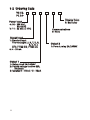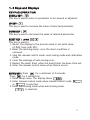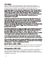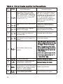
1
R
The Symbol calls attention to an operating procedure, practice, or the
like, which, if not correctly performed or adhered to, could result in
personal injury or damage to or destruction of part or all of the
product and system. Do not proceed beyond a warning symbol until
the indicated conditions are fully understood and met.
Installers
Read Chapter 1, 2
System Designer
Read All Chapters
Expert User
Read Page 11
NOTE:
It is strongly recommended that a process should
incorporate a LIMIT CONTROL like L91 which will shut down
the equipment at a preset process condition in order to
preclude possible damage to products or system.
Some programming parameters shown in this manual may not
be available on currently offered models.
Information in this user's manual is subject to change without
This manual is applicable for the products with software
version 23 and later version.
Copyright a April 2003, Eaton Corporation, all rights reserved. No
part of this publication may be reproduced, transmitted,
transcribed or stored in a retrieval system, or translated into any
language in any form by any means without the written permission
of Eaton Corporation.
2
Contents
Page No
Page No
Chapter 1 Overview
Chapter 4 Calibration --------45
1-1 General -------------------------5
1-2 Ordering Code ---------------8
1-3 Keys and Displays ------------9 Chapter 5 Specifications -----46
1-4 Menu Overview -------------11
1-5 Parameter Descriptions ----12 Appendix
A-1 Error Codes ------------------52
A-2 Warranty ----------------------53
Chapter 2 Installation
2-1
2-2
2-3
2-4
2-5
Unpaking ----------------------19
Mounting ----------------------19
Wiring precautions ----------21
Power Wiring -----------------23
Sensor Installation
Guidlines----------------------23
2-6 Sensor Input Wiring ---------24
2-7 Control Output Wiring ------24
2-8 Alarm Wiring -----------------27
Chapter 3 Programming
3-1 Lockout ------------------------28
3-2 Signal Input -------------------28
3-3 Control Outputs --------------29
3-4 Alarm ---------------------------34
3-5 Configure Display -----------35
3-6 Ramp ---------------------------36
3-7 Dwell Timer -------------------37
3-8 PV Shift ------------------------38
3-9 Digital Filter -------------------39
3-10 Failure Transfer -------------40
3-11 Auto-tuning ------------------41
3-12 Manual tuning --------------42
3-13 Manual Control -------------43
3
Figures & Tables
Figure
Figure
Figure
Figure
Figure
Figure
Figure
Figure
Figure
Figure
Figure
Figure
Figure
Figure
Figure
Figure
Figure
Figure
Figure
Figure
Figure
Figure
Figure
Figure
Figure
Table 1.1
Table 3.1
Table 3.2
Table A.1
4
Page No
1.1 Fuzzy Control Advantage ----------------------------------------------------------------6
1.2 Front Panel Description -----------------------------------------------------------------10
1.3 Display of Initial Stage -------------------------------------------------------------------10
2.1 Mounting Dimensions -------------------------------------------------------------------20
2.2 Lead Termination ------------------------------------------------------------------------22
2.3 Rear Terminal Connection --------------------------------------------------------------22
2.4 Power Supply Connections --------------------------------------------------------------23
2.5 Sensor Input Wiring ----------------------------------------------------------------------24
2.6 Output 1 Relay to Drive Load ----------------------------------------------------------24
2.7 Output 1 Relayto Drive Contactor ---------------------------------------------------25
2.8 Output 1 Pulsed Voltage to Drive SSR ---------------------------------------------25
2.9 Output 1 Linear Current ---------------------------------------------------------------26
2.10 Output 2 Relay to Drive Load --------------------------------------------------------26
2.11 Output 2 Relayto Drive Contactor --------------------------------------------------26
2.12 Alarm Output to Drive Load ----------------------------------------------------------27
2.13 Alarm Output to Drive Contactor ----------------------------------------------------27
3.1 Conversion Curve for Linear Type Process Value ---------------------------------29
3.2 Heat Only ON-OFF Control ------------------------------------------------------------30
3.3 Output 2 Deviation High Alarm --------------------------------------------------------33
3.4 Output 2 Process Low Alarm ----------------------------------------------------------33
3.5 RAMP Function ---------------------------------------------------------------------------36
3.6 Dwell Timer Function --------------------------------------------------------------------37
3.7 PV Shift Application ----------------------------------------------------------------------38
3.8 Filter Characteristics ---------------------------------------------------------------------39
3.9 Effects of PID Adjustment -------------------------------------------------------------44
Display Form of Characters -------------------------------------------------------------11
Heat-Cool Control Setup Value ---------------------------------------------------------29
PID Adjustment Guide --------------------------------------------------------------------43
Error Codes and Corrective Actions ---------------------------------------------------52
Chapter 1 Overview
1-1 General
The Fuzzy Logic plus PID microprocessor-based controller series,
incorporate a bright, easy to read 4-digit LED display, indicating
process value or set point value. The Fuzzy Logic technology
enables a process to reach a predetermined set point in the
shortest time, with the minimum of overshoot during power-up or
external load disturbance.
The TC/PC 24 is a 1/32 DIN size panel mount controller. These units
are powered by 11-26 or 90-250 VDC/VAC supply, incorporating a
2 amp control relay output as standard. The second output can be
used as cooling control, an alarm or dwell timer. There are
six types of alarm plus a dwell timer can be configured for the
second output.The units are fully programmable for PT100 and
thermocouple types J,K, T, E, B, R, S, N, L with no need to modify the
unit. The input signal is digitized by using a 18-bit A to D converter.
Its fast sampling rate allows the unit to control fast processes.
By using proprietary Fuzzy modified PID technology, the control
loop will minimize the overshoot and undershoot in a shortest
time. The following diagram is a comparison of results with and
without Fuzzy technology.
5
Temperature
PID control with properly tuned
PID + Fuzzy control
Set
point
Figure 1.1
Fuzzy Control
Advantage
Warm Up
Load Disturbance
Time
High Accuracy
The series are manufactured with custom designed ASIC(Application
Specific Integrated Circuit ) technology which contains a 18-bit A to
D converter for high resolution measurement ( true 0.1 BF resolution
for thermocouple and PT100 ) and a 15-bit D to A converter for linear
current or voltage control output. The ASIC technology provides
improved operating performance, low cost, enhanced reliability and
higher density.
Fast Sampling Rate
The sampling rate of the input A to D converter reaches 5 times/second.
The fast sampling rate allows this series to control fast processes.
Fuzzy Control
The function of Fuzzy control is to adjust PID parameters from time to
time in order to make manipulation output value more flexible and
adaptive to various processes. The results is to enable a process to
reach a predetermined set point in the shortest time, with the minimum
of overshoot and undershoot during power-up or external load
disturbance.
6
Auto-tune
The auto-tune function allows the user to simplify initial setup for a
new system. A clever algorithm is provided to obtain an optimal set
of control parameters for the process, and it can be applied either as
the process is warming up ( cold start ) or as the process has been
in steady state ( warm start ).
Lockout Protection
According to actual security requirement, one of four lockout levels
can be selected to prevent the unit from being changed abnormally.
Bumpless Transfer
Bumpless transfer allows the controller to continue to control by
using its previous value as the sensor breaks. Hence, the process
can be well controlled temporarily as if the sensor is normal.
Soft-start Ramp
The ramping function is performed during power up as well as any
time the set point is changed. It can be ramping up or ramping
down. The process value will reach the set point with a predetermined
constant rate.
Digital Filter
A first order low pass filter with a programmable time constant is used
to improve the stability of process value. This is particularly useful in
certain application where the process value is too unstable to be read.
7
1-2 Ordering Code
TC 24PC 24Power Input
4: 90 - 250 VAC,
50/60 HZ
5: 11 - 26 VAC or VDC
Signal Input
1: Standard Input
Thermocouple: J, K, T, E, B,
R, S, N, L
RTD: PT100 DIN, PT100 JIS
6: 4 - 20 mA
Output 1
1: Relay rated 2A/240VAC
2: Pulsed voltage to drive SSR,
5V/30mA
3: Isolated 4 - 20mA / 0 - 20mA
8
Display Color
0: Red color
Communications
0: None
Output 2
1: Form A relay 2A/240VAC
1- 3 Keys and Displays
KEYPAD OPERATION
SCROLL KEY :
This key is used to select a parameter to be viewed or adjusted.
UP KEY :
This key is used to increase the value of selected parameter.
DOWN KEY :
This key is used to decrease the value of selected parameter.
RESET KEY : press
This key is used to:
1. Revert the display to the process value or set point value
(if DISP is set with SP1).
2. Reset the latching alarm, once the alarm condition is
removed.
3. Stop the manual control mode, auto-tuning mode and calibration
mode.
4. Clear the message of auto-tuning error.
5. Restart the dwell timer when the dwell timer has been time out.
6. Enter the manual control menu when failure occurs.
for a minimum of 5 seconds.
ENTER KEY : Press
Press
for 5 seconds to:
1. Enter setup menu. The display shows
.
2. Enter manual control mode when manual control mode
or
is selected.
3. Enter auto-tuning mode when auto-tuning mode
is selected.
9
Output 2
Indicator
Output 1
Indicator
O1
O2
C
Figure 1.3
Front Panel Description
Table 1.1 Display Form of Characters
A
B
C
c
D
E
F
G
H
h
I
J
K
L
M
N
O
P
Q
R
S
T
U
V
W
X
Y
Z
?
=
Display program code of the product
for 2.5 seconds.
O1
O2
C
The diagram shows program no. 33
with version 24.
Figure 1.4
Display of Initial Stage
10
1- 5 Menu Overview
User menu *1
(DISP=PV)
PV
Setup menu*1
(DISP=SP1)
or
Calibration Mode
7.4 sec.
6.2 sec.
SP1
2 sec.
SP1
or
Value
Manual
Mode
H
5 sec.
C
5 sec.
Manual
Mode
5 sec.
Auto-tuning
Mode
A-T
INPT
UNIT
DP
PB
TI
TD
CYC1
ADDR
*2
Value
PV
SP2
Value
Value
LOCK
INPT
UNIT
DP
INLO
INHI
SP1L
SP1H
SHIF
FILT
DISP
PB
TI
TD
OUT1
O1TY
O1FT
O1HY
CYC1
OFST
RAMP
RR
OUT2
O2TY
O2FT
O2HY
CYC2
CPB
DB
ALMD
COMM
ADDR
BAUD
DATA
PARI
STOP
RELO
REHI
SEL1
SEL2
SEL3
SEL4
SEL5
SEL6
SEL7
SEL8
Value
ADLO
ADHI
RTDL
RTDH
CJLO
CJHI
Value
Value
Press
for
5 seconds to
perform calibration.
Applying these modes will
break the control loop
and change some of the
previous setting data.
Make sure that the
system will allow application
of these modes.
*1:
The flow chart shows a
complete listing of all
parameters. For actual
application the number of
available parameters
depends on setup
conditions, and should be
less than that shown in
the flow chart.
Release
, press
*2: again for 2 to 3 seconds, then
release to enter the
calibration menu.
Value
11
1-6 Parameter Descriptions
Parameter
Notation
Range
Parameter Description
SP1
Set point for output 1
Low: SP1L
SP2
Set point for output 2
when output 2 performs
alarm function or dwell
timer
Low: -19999
0
1
LOCK
Select parameters to be
locked
2
3
0
1
2
3
Input sensor selection
High :45536
: No parameter
is locked
: Setup data are
locked
: Setup data and
User data except Set
point are locked
: All data are locked
6
: S type thermocouple
7
: N type thermocouple
8
: L type thermocouple
: PT 100 ohms DIN
curve
10
: PT 100 ohms JIS
11
: 4 - 20 mA linear
12
: 0 - 20 mA linear
13
: 0 - 60 mV linear
curve
14
15
16
17
12
10.0 °C
(18.0°F)
0
: T type thermocouple
: E type thermocouple
: B type thermocouple
: R type thermocouple
9
25.0 °C
(77.0°F)
: J type thermocouple
: K type thermocouple
5
4
INPT
High :SP1H
Default
Value
current input
current input
millivolt input
: 0 - 1V linear voltage
input
: 0 - 5V linear voltage
input
: 1 - 5V linear voltage
input
: 0 - 10V linear voltage
input
1
(0)
Parameter
Notation
UNIT
DP
Input unit selection
Decimal point selection
Default
Value
Range
Parameter Description
0
: Degree C unit
1
: Degree F unit
2
: Process unit
0
: No decimal
point
1
: 1 decimal digit
2
: 2 decimal digits
3
: 3 decimal digits
0
(1)
1
INLO
Input low sale value
Low: -19999
High: 45486
-17.8°C
( 0 °F )
INHI
Input high scale value
Low: INLO+50
High: 45536
93.3 °C
(200.0°F)
SP1L
Low limit of set point
value
Low: -19999
High: 45536
-17.8°C
(0 °F)
Low: SP1L
High: 45536 537.8°C
(1000°F)
SP1H
High limit of set point
value
SHIF
PV shift (offset) value
FILT
Filter damping time
constant of PV
Low:
-200.0°C High: 200.0°C
(-360.0°F)
( 360.0°F)
0
: 0 second time
1 High:
: 0.2 second time
2
: 0.5 second time
3
: 1 second time
4
: 2 seconds time
5
: 5 seconds time
6
:
7
:
8
:
9
:
0.0
constant
constant
constant
constant
constant
2
constant
10 seconds time
constant
20 seconds time
constant
30 seconds time
constant
60 seconds time
constant
13
Parameter
Notation
Parameter Description
DISP
Normal display selection
Range
0
: Display process
value normally
1
: Display set point 1
value normally
High: 500.0 °C
(900.0 °F)
0
10.0 °C
(18.0 °F)
PB
Proportional band value
Low: 0
TI
Integral time value
Low: 0
High: 1000 sec
100
TD
Derivative time value
Low: 0
High: 360.0 sec
25.0
OUT1
O1TY
0
: Reverse (heating )
1
: Direct (cooling)
Output 1 function
Output 1 signal type
control action
0
control action
0
: Relay output
1
: Solid state relay
drive output
2
: Solid state relay
output
3
: 4-20 mA current
module
4
: 0 - 20 mA current
5
: 0 - 1V voltage
6
: 0 - 5V voltage
7
: 1 - 5V voltage
8
: 0 - 10V voltage
module
0
module
module
module
module
O1FT
Output 1 failure transfer
mode
Select BPLS ( bumpless
transfer ) or 0.0 ~ 100.0 % to
continue output 1 control
function as the unit fails, or
select OFF (0) or ON (1)
for ON-OFF control.
O1HY
Output 1 ON-OFF control
hysteresis
Low: 0.1 High: 50.0°C(90.0°F)
CYC1
Output 1 cycle time
Low: 0.1 High: 90.0 sec.
OFST
Offset value for P control
Low: 0
14
Default
Value
High: 100.0 %
0
0.1°C
(0.2°F)
18.0
25.0
Parameter Parameter Description
Notation
RAMP
Range
Ramp function
selection
0
: No Ramp Function
1
: Use unit/minute as
Ramp Rate
: Use unit/hour as
Ramp Rate
2
RR
OUT2
Ramp rate
0
: Output 2 No Function
: Dwell timer action
2
: Deviation High Alarm
3
: Deviation Low Alarm
4
6
: Deviation band out of
band Alarm
: Deviation band in
band Alarm
: Process High Alarm
7
: Process Low Alarm
8
: Cooling PID Function
Output 2 function
O2FT
Output 2 signal type
Output 2 failure
transfer mode
500.0°C
(900.0 °F)
1
5
O2TY
High:
Low: 0
0
: Relay output
1
: Solid state relay
2
: Solid state relay
3
: 4 - 20 mA current
4
: 0 - 20 mA current
5
:
6
:
7
:
8
:
Default
Value
0
0.0
2
drive output
output
module
0
module
0 - 1V voltage
module
0 - 5V voltage
module
1 - 5V voltage
module
0 - 10V voltage
module
Select BPLS ( bumpless transfer )
or 0.0 ~ 100.0 % to continue
output 2 control function as the
unit fails, or select ON (0) or
OFF (1) for alarm and dwell timer
function.
0
15
Parameter Parameter Description
Notation
O2HY
Range
Output 2 hysteresis
value when output 2
performs alarm
function
Low: 0.1
Default
Value
High: 50.0 °C
(90.0 °F)
0.1 °C
(0.2 °F)
CYC2
Output 2 cycle time
Low: 0.1
High: 90.0 sec.
18.0
CPB
Cooling proportional
band value
Low: 50
High: 300 %
100
DB
Heating-cooling dead
band (negative value=
overlap)
Low: -36.0
High: 36.0 %
0
ALMD
COMM
ADDR
BAUD
16
Alarm operation mode
Communication
function
Address assignment of
digital communication
Baud rate of digital
communication
0
: Normal alarm action
1
2
3
: Latching alarm action
: Hold alarm action
0
: No communication
1
: Modbus RTU mode
protocol
2
:4-20mA retransmission
output
3
:0-20mA retransmission
output
4
:0-5V retransmission
output
5
:1-5V retransmission
output
6
:0-10V retransmission
output
Low: 1
0
: Latching & Hold action
1
High: 255
0
: 2.4 Kbits/s baud rate
1
: 4.8 Kbits/s baud rate
2
: 9.6 Kbits/s baud rate
3
: 14.4 Kbits/s baud rate
4
: 19.2 Kbits/s baud rate
5
: 28.8 Kbits/s baud rate
6
: 38.4 Kbits/s baud rate
2
Parameter Parameter Description
Notation
DATA
Data bit count of digital
communication
PARI
Parity bit of digital
communication
Range
0
: 7 data bits
1
: 8 data bits
0
: Even parity
1
: Odd parity
2
: No parity bit
0
: One stop bit
1
: Two stop bits
Default
Value
1
0
STOP
Stop bit count of digital
communication
RELO
Retransmission low
scale value
Low: -19999
High: 45536
0.0 °C
(32.0 °F)
REHI
Retransmission high
scale value
Low: -19999
High: 45536
100.0 °C
(212.0 °F)
SEL1
Select 1st parameter for
user menu
0
:No parameter selected
1
:LOCK is put ahead
2
:INPT is put ahead
3
:UNIT is put ahead
4
:DP is put ahead
5
:SHIF is put ahead
6
:PB is put ahead
7
:TI is put ahead
8
:TD is put ahead
9
:O1HY is put ahead
10
:CYC1 is put ahead
11
:OFST is put ahead
12
:RR is put ahead
13
:O2HY is put ahead
14
:CYC2 is put ahead
15
:CPB is put ahead
16
:DB is put ahead
17
:ADDR is put ahead
0
2
17
Parameter Parameter Description
Notation
Range
Default
Value
SEL2
Select 2nd parameter
for user menu
Same as SEL1
3
SEL3
Select 3rd parameter
for user menu
Same as SEL1
4
SEL4
Select 4th parameter
for user menu
Same as SEL1
6
SEL5
Select 5th parameter
for user menu
Same as SEL1
7
SEL6
Select 6th parameter
for user menu
Same as SEL1
8
SEL7
Select 7th parameter
for user menu
Same as SEL1
10
SEL8
Select 8th parameter
for user menu
Same as SEL1
17
18
Chapter 2 Installation
Dangerous voltages capable of causing death are
sometimes present in this instrument. Before installation or
beginning any cleaning or troubleshooting procedures the power
to all equipment must be switched off and isolated. Units
suspected of being faulty must be disconnected and removed to
a properly equipped workshop for testing and repair. Component
replacement and internal adjustments must be made by a
qualified maintenance person only.
This instrument is protected throughout by Double
Insulation
. To minimize the possibility of fire or shock, do
not expose this instrument to rain or excessive moisture.
Do not use this instrument in areas under hazardous
conditions such as excessive shock, vibration, dirt, moisture,
corrosive gases or oil. The ambient temperature of the areas
should not exceed the maximum rating specified in Chapter 6.
Remove stains from this instrument using a soft, dry cloth.
Don't use harsh chemicals, volatile solvent such as thinner or
strong detergents to clean the instrument in order to avoid
deformation or discoloration.
2-1 Unpacking
Upon receipt of the shipment remove the unit from the carton and
inspect the unit for shipping damage. If any damage due to transit,
report and claim with the carrier. Write down the model number,
serial number, and date code for future reference when
corresponding with our service center. The serial number (S/N) and
date code (D/C) are labeled on the box and the housing of control.
2-2 Mounting
Make panel cutout to dimension shown in Figure 2.1.
Remove both mounting clamps and insert the controller into
panel cutout. Reinstall the mounting clamps. Gently tighten
the screws in the clamp until the controller front panel is fitted
snugly in the cutout.
19
Figure 2.1 Mounting Dimensions
MOUNTING
CLAMP
_
45 +0.5
0
+0.3
22.2 _
0
SCREW
Panel
98.0mm
12.5mm
10.0mm
20
2 - 3 Wiring Precautions
Before wiring, verify the label for correct model number and
options. Switch off the power while checking.
Care must be taken to ensure that maximum voltage rating
specified on the label are not exceeded.
It is recommended that power of these units to be protected by
fuses or circuit breakers rated at the minimum value possible.
All units should be installed inside a suitably grounded metal
enclosure to prevent live parts being accessible from human
hands and metal tools.
All wiring must conform to appropriate standards of good practice
and local codes and regulations. Wiring must be suitable for
voltage, current, and temperature rating of the system.
Beware not to over-tighten the terminal screws. The torque should
not exceed 1 N-m ( 8.9 Lb-in or 10.2 KgF-cm )
Unused control terminals should not be used as jumper points as
they may be internally connected, causing damage to the unit.
Verify that the ratings of the output devices and the inputs as
specified in Chapter 6 are not exceeded.
Except the thermocouple wiring, all wiring should use stranded
copper conductor with maximum gauge 18 AWG.
21
2.0mm
0.08" max.
Figure 2.2
Lead Termination
4.5 ~7.0 mm
0.18" ~0.27"
OP1
OP2
L
N
90-250 VAC
47-63 Hz,10VA
PTA
V+,mA+
TC+
PTB
8
9
RTD
4
5
6
V_,mA _
TC _
PTB
10
COM
11
2A/240 VAC
12
13
14
B
V
I
_
50°C max. Air ambient
Use copper conductors
(except on T/C input )
Figure 2.3
Rear Terminal Connection
22
7
_
B
+
CAT. I I
_
3
2A/240 VAC
+
A
+
2
+
1
_
2 - 4 Power Wiring
The controller is supplied to operate at 11-26 VAC / VDC or 90-250
VAC. Check that the installation voltage corresponds with the power
rating indicated on the product label before connecting power to
the controller. Near the controller a fuse and a switch rated at
2A/250VAC should be equiped as shown in the following diagram.
L
N
1
2
Fuse
2A/250VAC
90 ~ 250 VAC or
11 ~ 26 VAC / VDC
Figure 2.4 Power Supply Connections
This equipment is designed for installation in an enclosure
which provides adequate protection against electric shock. The
enclosure must be connected to earth ground.
Local requirements regarding electrical installation should be rigidly
observed. Consideration should be given to prevent from
unauthorized access to the power terminals.
2-5 Sensor Installation Guidelines
Proper sensor installation can eliminate many problems in a
control system. The probe should be placed so that it can detect
any temperature change with minimal thermal lag. In a process
that requires fairly constant heat output, the probe should be
placed close to the heater. In a process where the heat demand is
variable, the probe should be close to the work area. Some
experiments with probe location are often required to find this
optimal position.
In a liquid process, addition of a stirrer will help to eliminate
thermal lag. Since the thermocouple is basically a point
measuring device, placing more than one thermocouple in
parallel can provide an average temperature readout and
produce better results in most air heated processes.
23
Proper sensor type is also a very important factor to obtain precise
measurements. The sensor must have the correct temperature range
to meet the process requirements. In special processes the sensor
might need to have different requirements such as leak-proof, antivibration, antiseptic, etc.
+/-4
Standard sensor limits of error are +/4 degrees F (+/(+/- 2 degrees C )
or 0.75% of sensed temperature (half that for special) plus drift
caused by improper protection or an over-temperature occurrence.
This error is far greater than controller error and cannot be corrected
on the sensor except by proper selection and replacement.
2-6 Sensor Input Wiring
A
+
RTD
+
TC-, VPTB, mA-
8
9
10
+
PTA
TC+, V+
PTB, mA+
B
_
_V _
B
TC
V mA RTD
Figure 2.5 Sensor Input Wiring
2-7 Control Output Wiring
5
6
LOAD
Figure 2.6
Output 1 Relay to Drive Load
24
120V/240VAC
Mains Supply
5
6
Figure 2.7
Output 1 Relay to Drive Contactor
+
+
5
6
_
_
5V
33
+
33
0V
Figure 2.8 Output 1 Pulsed Voltage to Drive SSR
25
+
5
6
Load
_
Figure 2.9 Output 1 Linear Current
3
4
LOAD
120V/240VAC
Mains Supply
Figure 2.10
Output 2 Relay to Drive Load
3
4
Figure 2.11
Output 2 Relay to Drive Contactor
26
2-8 Alarm Wiring
3
4
LOAD
120V/240VAC
Figure 2.12 Alarm Output to Drive Load
3
4
Figure 2.13 Alarm Output to Drive Contactor
27
Chapter 3 Programming
Press
for 5 seconds and release to enter setup menu. Press
to select the desired parameter. The display indicates the parameter
symbol. Press
or
to view or adjust the value of the selected
parameter.
3-1 Lockout
There are four security levels can be selected by using LOCK
parameter.
If NONE is selected for LOCK, then no parameter is locked.
If SET is selected for LOCK, then all setup data are locked.
If USER is selected for LOCK, then all setup data as well as user data
(refer to section 1-5
1-5) except set point are locked to prevent from being
changed.
If ALL is selected for LOCK, then all parameters are locked to prevent
from being changed.
3-2 Signal Input
INPT: Selects the sensor type or signal type for signal input.
Range: (thermocouple) J_TC, K_TC, T_TC, E_TC, B_TC, R_TC
S_TC, N_TC, L_TC
(RTD) PT.DN, PT.JS
(linear) 4-20, 0-20, 0-60, 0-1V, 0-5V, 1-5V, 0-10
UNIT: Selects the process unit
Range: °C, °F, PU(process unit). If the unit is neither °C nor °F,
then selects PU.
DP: Selects the resolution of process value.
Range: (for T/C and RTD) NO DP, 1-DP
(for linear) NO DP, 1-DP, 2-DP, 3-DP
INLO: Selects the low scale value for the linear type input.
If 4 - 20 mA is selected for INPT, let SL specifies the input signal low
(ie. 4 mA ), SH specifies the input signal high (ie. 20 mA), S specifies
the current input signal value, the conversion curve of the process
value is shown as follows :
28
process value
INHI
PV
INLO
input signal
SL S SH
3-3 Control Outputs
There are 4 kinds of control modes can be configured as shown in
Table 3.1
Table 3.1 Heat-Cool Control Setup Value
Control
Modes
OUT1
Heat only
REVR
Cool only
DIRT
Heat: PID
Cool: ON-OFF
REVR
DE.HI
Heat: PID
Cool: PID
REVR
COOL
OUT2
: Don't care
:Adjust to met process
requirements
O1HY
O2HY
CPB
DB
:Required if ON-OFF control
is configured
29
PV
SP1
Dead band = O1HY
SP1 O1HY
OUT1 Action
Time
ON
OFF
Time
30
Cool only control:
31
You can use the
program for the new process or directly
set the appropriate values for PB, TI & TD according to experience.
If the control behavior is still inadequate, then use
to improve the control. See
for manual tuning.
Adjustment of CPB is related to the cooling media used. For air
used as cooling media, adjust CPB at 100(%).For oil used as cooling
media, adjust CPB at 125(%). For water used as cooling media,
adjust CPB at 250(%).
DB Programming: Adjustment of DB is dependent on the system
requirements. If more positive value of DB ( greater dead band ) is
used, an unwanted cooling action can be avoided but an excessive
overshoot over the set point will occur. If more negative value of
DB ( greater overlap ) is used, an excessive overshoot over the set
point can be minimized but an unwanted cooling action will occur.
It is adjustable in the range -36.0% to 36.0 % of PB. A negative DB
value shows an overlap area over which both outputs are active. A
positive DB value shows a dead band area over which neither
Output 2 ON-OFF Control ( Alarm function ): Output 2 can also be
configured as alarm function. There are 4 alarm functions that can
be selected for output 2: DE.HI (deviation high alarm ),
DE.LO (deviation low alarm ), PV.HI (process high alarm ) and PV.LO
( process low alarm ). Refer to Figure 3.3 and Figure 3.4 for the
description of deviation alarm and process alarm.
32
PV
OUT2=DE.HI
SV+SP2
SV+SP2-O2HY
OUT2 Action
Time
ON
OFF
Time
PV
SP2+O2HY
SP2
OUT2 Action
Time
ON
OFF
Time
33
Output 2 can be selected as alarm output. There are 6 types of
alarm functions and one dwell timer can be selected, and four kinds
of alarm modes ( ALMD ) are available for each alarm function.
A process alarm sets two absolute trigger levels. When the process is
PV.HI )) occurs,
higher than SP2, a process high alarm ( PV.HI
occurs, and
and the
the alarm
alarm
is off as the process is lower than SP2-O2HY. When the process is
lower than SP2, a process low alarm ( PV.LO ) occurs and the alarm is
off as the process is higher than SP2+O2HY. A process alarm is
independent of set point.
A deviation alarm alerts the user when the process deviates too far
from set point. When the process is higher than SV+SP2, a deviation
high alarm (DE.HI) occurs and the alarm is off as the process is lower
than SV+SP2-O2HY. When the process is lower than SV+SP2, a
deviation low alarm (DE.LO) occurs and the alarm is off as the process
is higher than SV+SP2+O2HY. Trigger level of deviation alarm is
moving with set point.
A deviation band alarm presets two trigger levels relative to set point.
The two trigger levels are SV+SP2 and SV - SP2 for alarm. When the
process is higher than ( SV+SP2 ) or lower than ( SV - SP2 ), a
deviation band high alarm ( DB.HI ) occurs. When the process is within
the trigger levels, a deviation band low alarm (DB.LO) occurs.
In the above descriptions SV denotes the current set point value for
control which is different from SP1 as the ramp function is performed.
There are four types of alarm modes available for each alarm function,
these are: Normal alarm, Latching alarm, Holding alarm and Latching/
Holding alarm. They are described as follows:
Normal Alarm : ALMD = NORM
When a normal alarm is selected, the alarm output is de-energized
in the non-alarm condition and energized in an alarm condition.
Latching Alarm : ALMD = LTCH
If a latching alarm is selected, once the alarm output is energized, it
will remain unchanged even if the alarm condition is cleared. The
latching alarm is reset when the RESET key is pressed, once the alarm
condition is removed.
34
Holding Alarm : ALMD = HOLD
A holding alarm prevents an alarm from power up. The alarm is
enabled only when the process reaches the set point value. Afterwards,
the alarm performs same function as normal alarm.
Latching / Holding Alarm : ALMD = LT.HO
A latching / holding alarm performs both holding and latching function.
The latching alarm is reset when the RESET key is pressed, once the
alarm condition is removed.
Alarm Failure Transfer is activated as the unit enters failure mode.
mode
Alarm will go on if ON is set for O2FT and go off if OFF is
set for O2FT
O2FT. The unit will enter failure mode when sensor break
occurs or if the A-D converter of the unit fails.
The controller can be configured to display the process value by
selecting PV for DISP or to display the set point value by selecting
SP1 for DISP in the normal condition.
If LOCK is set with NONE, OUT2 is set with DEHI, DISP is set with PV,
set SEL1=SHIF, SEL2=ADDR. SEL3=PB, SEL4~SEL8=NONE,
then the display scrolling becomes:
If LOCK is set with NONE, OUT1 is set with REVR,nonzero value is set
for PB and TI, OUT2 is set with COOL, DISP is set with SP1, set
SEL1=INPT, SEL2=PB, SEL3=TI, SEL4~SEL8=NONE, then the
display scrolling becomes:
35
3 - 6 Ra mp
36
Output 2 can be configured as dwell timer by selecting TIMR for
OUT2. As the dwell timer is configured, the parameter SP2 is used
for dwell time adjustment. The dwell time is measured in minutes
ranging from 0.1 to 4553.6 minutes. Once the process reaches the
setpoint the dwell timer starts to time down to zero ( time out ).
The timer relay will remain unchanged until time out. The dwell
timer operation is shown in the following diagram.
After time out the dwell timer can be restarted by pressing the
RESET key.
The timer stops timing during the manual control mode, failure
mode, calibration period and auto-tuning period.
PV
SP
ALM
Time
SP3
power off or
touch RESET key
ON
OFF
Time
Timer starts
37
Object
Heater
Object
Heater
Heat
Transfer
165 C
Sensor
C
35 C temperature
difference is observed
SHIF= 0
38
Heater
Heat
Transfer
165 C
200 C
Object
Heat
Transfer
200 C
200 C
Sensor
C
Adjust SHIF
SHIF= -35 C
Supply more heat
235 C
Sensor
C
Display is stable
SHIF= -35 C
PV=SV
In certain application the process value is too unstable to be read.
To improve this a programmable low pass filter incorporated in the
controller can be used. This is a first order filter with time constant
specified by
parameter . The default value of FILT is 0.5 sec.
before shipping. Adjust FILT to change the time constant from 0 to
60 seconds. 0 second represents no filter is applied to the input
signal. The filter is characterized by the following diagram.
39
The controller will enter
as one of the following conditions
occurs:
1.
occurs due to the input sensor break or input current below
1mA if 4-20 mA is selected or input voltage below 0.25V if 1-5 V is
selected .
2.
occurs due to the A-D converter of the controller fails.
The output 1 and output 2 will perform the
the controller enters failure mode.
40
function as
1. The system has been installed normally.
2. Set the correct values for the setup menu of the unit.
But don't use a zero value for PB and TI, otherwise, the
auto-tuning program will be disabled. The LOCK parameter
should be set at NONE.
3. Set the set point to a normal operating value or a lower value if
overshooting beyond the normal process value is likely to
cause damage.
4. Press
several times until
appears on the
display.
5. Press
for at least 5 seconds. The display will begin to
flash and the auto-tuning procedure will begin.
The ramping function, if used, will be disabled once auto-tuning
mode is entered.
The auto-tuning mode is disabled as soon as either failure mode
or manual control mode occurs.
41
The auto-tuning can be applied either as the process is warming
up ( Cold Start ) or as the process has been in steady state (
Warm Start ).
After the auto-tuning procedures are completed, the display
will stop flashing and the unit will revert to PID control, using
he new PID values. The PID values obtained are stored in the
nonvolatile memory.
In certain applications ( very few ) using auto-tuning to tune a
process may be inadequate for the control requirements, this is
when manual tuning should be used.
If the control performance by using auto-tuning is still
unsatisfactory, the following rules can be applied for further
adjustment of PID values :
42
43
44
Chapter 4 Calibration
CALIBRATION SHOULD BE DONE ONLY BY EXPERIENCED
PERSONNEL WITH APPROPRIATE CALIBRATION EQUIPMENT.
THE USE OF A CERTIFIED CALIBRATION LABORATORY IS
HIGHLY RECOMMENDED.
FOR DETAILED CALIBRATION INSTRUCTIONS, OR FOR
ADDITIONAL INFORMATION, PLEASE CONTACT YOUR LOCAL
EATON REPRESENTATIVE OR CALL EATON CARE AT
877-ETN-CARE.
45
Chapter 5 Specifications
46
47
Resolution :
48
49
50
51
Error Display
Code Symbol
4
Error Description
Illegal setup values been used:
Before COOL is used for OUT2,
DIRT ( cooling action ) has already
been used for OUT1, or PID mode
is not used for OUT1 ( that is PB
= 0, and / or TI = 0 )
Corrective Action
Check and correct setup values of
OUT2, PB, TI and OUT1. IF OUT2
is required for cooling control, the
control should use PID mode ( PB
= 0, TI = 0 ) and OUT1 should
use reverse mode (heating action)
, otherwise, don't use OUT2 for
cooling control.
10
Communication error: bad function Correct the communication
code
software to meet the protocol
requirements.
11
Communication error: register
address out of range
Don't issue an over-range
register address to the slave.
14
Communication error: attempt
to write a read-only data or a
protected data
Don't write a read-only data or a
protected data to the slave.
15
Communication error: write a
value which is out of range to a
register
Don't write an over-range data
to the slave register.
1.The PID values obtained after
auto-tuning procedure are out
of range. Retry auto-tuning.
26
Fail to perform auto-tuning
function
2.Don't change set point value
during auto-tuning procedure.
3.Use manual tuning instead of
auto-tuning.
4. Don't set a zero value for PB.
5. Don't set a zero value for TI.
6. Touch RESET key
29
EEPROM write error
Return to factory for repair.
30
Cold junction compensation for
thermocouple malfunction
Return to factory for repair.
39
Input sensor break, or input
current below 1 mA if 4-20 mA is
selected, or input voltage below Replace input sensor.
0.25V if 1 - 5V is selected
40
A to D converter or related
component(s) malfunction
52
Return to factory for repair.
WARRANTY
Eaton warrants all products against defects in material and
workmanship for a period of one (1) year from the date of shipment
to Buyer. This is a limited warranty limited to its terms. This
warranty is void if the product has been altered, misused, taken
apart or otherwise abused. ALL OTHER WARRANTIES, EXPRESS OR
IMPLIED, ARE EXCLUDED, INCLUDING BUT NOT LIMITED TO THE
IMPLIED WARRANTIES OF MERCHANT ABILITY AND FITNESS FOR
PURPOSE.
BUYERS’ REMEDIES
Eaton’s obligations and liabilities under the foregoing warranty are
limited to repair or replacement of the product without charge. To
receive the required Return Goods Authorization number (RGA),
contact your local Eaton distributor or Eaton Care at 877-ETN-CARE.
A charge is made for repairing after the expiration of the warranty.
IN NO EVENT SHALL EATON BE LIABLE FOR CLAIMS BASED UPON
BREACH OF EXPRESS OR IMPLIED WARRANTY OR NEGLIGENCE OR ANY
OTHER DAMAGES WHETHER DIRECT, IMMEDIATE, FORESEEABLE,
CONSEQUENTIAL OR SPECIAL OR FOR ANY EXPENSES INCURRED BY
REASON OF THE USE OR MISUSE, SALE OR FABRICATION OF PRODUCTS
WHICH DO OR DO NOT CONFORM TO THE TERMS AND CONDITIONS OF
THIS CONTRACT.
INDEMNIFICATION
Buyer agrees to hold Eaton harmless from, defend, and indemnify
Eaton against damages, claims, and expenses arising out of
subsequent sales of Durant products or products containing
components manufactured by Eaton and based upon personal
injuries, deaths, property damage, lost profits, and other matters
for which Buyer, its employees or sub-contractors are or may be to
any extent liable, including without limitation penalties imposed by
the Consumer Product Safety Act (P.L.92-573) and liability imposed
upon any person pursuant to the Magnuson-Moss Warranty Act
(P.L.93.637), as now in effect or as amended hereafter. The
warranties and remedies provided for herein are available to Buyer
and shall not extend to any other person.
53