1
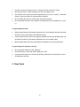
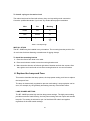
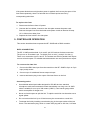
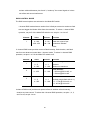
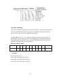
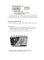
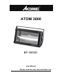
ATOM 3000 BF-3000D User Manual Please read the user manual before use Table of Contents Safety Information……………………………………………………. 3 Rear Panel……………………………………………………………. 4 Preparation for Use…………………………………………………...5 How to replace the Lamp and fuse………………………………….6 Controller Operation………………………………………………….. 8 Stand-alone Operation……………………………………………….12 Remote Control……………………………………………………….12 Test Function………………………………………………………….14 Technical Specification……………………………………………….15 1B 1. Safety Information Warning: This product is for professional use only! It is not for household use. The BF-3000D presents risks of lethal or severe injury due to fire and heat, electric shock, ultraviolet radiation, and falls. Flashing light is also known to trigger epileptic seizures in persons who are photosensitive. Read this manual before powering or installing the fixture, follow the safety precautions listed below and observe all warnings in this manual and printed on the fixture. To guard against electric shock Disconnect the fixture from AC power and allow the flash capacitor to discharge for 1 minute before changing the lamp or fuse, and when not in use. Do not remove the rear cover: there are no user-serviceable parts inside. Always ground (earth) the fixture electrically. Use only a source of AC power that complies with local building and electrical codes and has both overload and ground-fault protection. Do not expose the fixture to rain or moisture. Replace the lamp only as described or have it replaced by corresponding service technician. To guard against UV radiation, burns, and fire Never operate the fixture with the front glass open, missing or damaged. Do not stare directly into the light. Never look at an exposed lamp while it is lit. Replace the lamp when it becomes defective or worn out. When replacing the lamp, allow the fixture to cool for at least 10 minutes before opening the fixture or removing the lamp. Never attempt to bypass the fuse. Always replace defective fuses with ones of the specified type and rating. Verify that the power feed cable is rated for the current draw of all connected fixtures. Keep all combustible materials (for example fabric, wood, paper) at least 0.5 meters (20 inches) away from the fixture. Keep flammable materials well away from the fixture. Minimum distance to illuminated surface is 10 meters. 2B Provide a minimum clearance of 0.1 meters (4 inches) around air vents. Never place filters or other materials over the front glass cover. The exterior of the fixture can reach temperatures up to 120°C (248°F). Allow the fixture to cool for at least 15 minutes before handling. Do not modify the fixture or install other than genuine parts. Do not operate the fixture if the ambient air temperature (Ta) exceeds 40°C (104° F). To guard against falls When suspending the fixture above ground level, verify that the structure can hold at least 10 times the weight of all installed devices. Verify that all external covers and rigging hardware are securely fastened and use an approved means of secondary attachment such as a safety cable. Block access below the work area whenever installing or removing the fixture. To guard against epileptic seizure Do not operate the fixture near stairways. Provide advance notice that strobe lighting is in use. Avoid extended periods of continuous flashing, particularly at frequencies of 10 to 20 flashes per second. 2. Rear Panel 3B 1, Main Power: AC230V 50/60HZ 2, Flash: indicate flash status 3, DMX signal interface: input/ output DMX signal 4, Power Indicator: indicator power status 5, Data: show signal status 6, Dip Address: Set signal address in 1/3/4 channel DMX mode 7, Mode: Dip switch to set function mode 3. Preparation for Use UNPAKING The BF- 3000D comes with the following items: PX-3000 xenon lamp (installed) Mounting bracket User manual The packing material protects the fixture during shipment; always use it to transport the fixture. AC POWER CONNECTION BF-3000D should be connected with AC power 230V, 50/ 60Hz. Request use 32amp 10.3 x 38mm time-delay fuse. Use 14 AWG or 2.5 mm2 minimum power feed cables and keep runs as short as possible. 4B To install a plug on the mains lead The mains lead must be fitted with a heavy duty cord cap with ground connection. Consult a qualified electrician if you have any doubts about proper installation. Wire Pin Marking brown live “L” blue neutral “N” yellow/green ground Table 1: Cord cap wirings INSTALLATION The BF- 3000D may be installed in any orientation. The mounting bracket provides five 12 mm holes for direct fastening or attachment of rigging clamps. To install the mounting bracket 1. Place the fixture face down on a table. 2. Place an aluminum washer on each mounting bracket stud. 3. Make clear the direction of left and right side of bracket and lock the screws. After that, tighten one hand knob to lock the mounting bracket in one end of bracket. 4. Replace the Lamp and Fuse This section describes the lamp options, the lamp power setting, and how to replace the lamp and fuse. The lamp is electronically regulated to prevent overheating. Lamp regulation can be seen, for example, by the gradually decreasing intensity of the blinder effect. LAMP POWER SETTING The BF- 3000D provides high and low lamp power settings. The high power setting provides maximum flash intensity; the low power setting reduces output and extends lamp life. The setting is selected on pin 6 of the Mode DIP switch and applies regardless of the other switch settings. 5B APPROVED LAMP Warning: Only PX-3000 xenon lamp is approved in the BF-3000D. Installing a lamp that is not approved may create a safety hazard or damage the fixture! LAMP REPLACEMENT ON/ OFF state of the can be shown with Flash LED on the rear panel. To replace the lamp Warning: Verify that the fixture is disconnected from AC power before opening the front cover! Also, pay more attention to the location and installation of wiring before replacement. 1. Disconnect the fixture from AC power and allow the capacitor to discharge for 1 minute. 2. When the fixture is cool, remove the two marked screws on the sides of the fixture and open the front glass cover. 3. Disconnect the lamp wires at the screw terminals. Lift the old lamp out of the holder. 4. Replace a new lamp instead of the old. 5. Lift and turn the lamp over so that the leads loop around the ends as shown, then press the lamp into the clips. 6. Close the front cover and tighten the side screws before applying power. FUSE REPLACEMENT The BF- 3000D uses a 32 amp time-delay fuse for protection against current overload. 6B If the power diode does not light when power is applied, the fuse may be spent. If the fuse blows repeatedly, there is a fault with the unit that requires service by corresponding technician. To replace the fuse 1. Disconnect the fixture from AC power. 2. Unscrew the fuse holder, located on the side plate nearest the power cord. Remove the spent fuse from the holder and replace it with an identical 32 amp 10.3 x 38 mm time-delay fuse. 3. Replace the fuse holder in the side plate. 5. CONTROLLER OPERATION This section describes how to operate the BF- 3000D with a DMX controller. DATA CONNECTION The BF- 3 000D provides both 3- pin and 5- pin XLR sockets for data connection. The pin-out on all sockets is pin 1 to shield, pin 2 to cold (-), and pin 3 to hot (+). There is no connection to pins 4 and 5. The sockets are wired in parallel: both inputs connect to both outputs. For reliable data transmission use one input and one output! To connect the data link 1. Connect the DMX data input from the controller to the BF- 3000D’s 3-pin or 5-pin input (male) socket. 2. Connect up to 31 additional fixtures output-to-input. 3. Insert a termination plug in the output of the last fixture on the link. Connecting notice Use shielded twisted-pair cable designed for RS-485 devices: standard microphone cable cannot transmit control data reliably over long runs. 24 AWG cable is suitable for runs up to 300 meters (1000 ft.). Use heavier gauge cable and/or an amplifier for longer runs. Never use both outputs to split the link. To split the serial link into branches use a signal splitter. Do not overload the link. Up to 32 devices may be connected on a serial link. Terminate the link by installing a termination plug in the output socket of the last fixture. The termination plug, which is a male XLR plug with a 120 ohm, 0.25 watt 7B resistor soldered between pins 2 and 3, “soaks up” the control signal so it does not reflect and cause interference. DMX CONTROL MODE The DMX control options are selected on the Mode DIP switch. 1-channel DMX mode allows to strobe from 0 flash per second to maximum flash rate and trigger the blinder effect from the controller. To select 1- channel DMX operation, set pin 5 of the Mode DIP switch to on; set pins 1 to 4 to off. Channel Value Percent 1 0 - 249 0 - 98 250 - 255 98 - 100 Function Flash rate, slow to fast Continuous “Blinder” effect 3- channel DMX mode provides control of flash intensity, flash duration, and flash rate for more advanced control than 1-channel mode. To select 3- channel DMX operation, set pins 1 to 5 of the Mode DIP switch to off. Channel 1 2 Value Percent 0-5 0-1 6 - 255 2 - 100 Function Flash intensity Blackout Minimum to maximum Flash duration 0 - 255 0 - 100 0 - 650 ms @ 50 Hz AC, or 0 - 530 ms @ 60 Hz AC Flash rate 3 0-5 0-1 6 - 255 2 - 100 No flash (single flash with ch. 1) 0.5 - 17 Hz @ 50 Hz AC, or 0.6 - 20 Hz @ 60 Hz AC 4-channel DMX mode provides six special effects in addition to flash intensity, duration and rate control. To select this 4-channel DMX operation, set pins 1, 2, 3, and 5 to off; set pin 4 to on. 8B CONTROL ADDRESS The control address, also known as the start channel, is the first channel used to receive instructions from the controller. The address may be any channel from 1 to 511 and is set on the Address DIP switch. The BF-3000D uses 1, 3, or 4 channels depending on the control mode. For independent control, each fixture must be assigned its own address and non overlapping control channels. Two or more BF-3000Ds may share the same address if individual control is not required. DMX 512 Address Chart: Dip-switches #1 #2 #3 #4 #5 #6 #7 #8 #9 #10 Value 1 2 4 8 16 32 64 128 256 No effect • Examples: Unit 1:dip / on: #1 (=1) Unit 2:dip / on: #1, #2, #3 (1+2+4=7) Unit 3:dip / on: #1, #3, #4 (1+4+8=13) Unit 4:dip / on: #1, #2, #5 (1+2+16=19) 9B DMX CONTROL SUMMARY Intensity Flash intensity can be set from minimum (blackout) to maximum on channel 1 in the 3- and 4-channel DMX modes. Intensity is maximum in 1-channel DMX mode. The maximum intensity can be reduced by selecting low power mode as described Duration Flash duration can be set from 0 to 650 ms on 50 Hz power supplies, or 0 to 530 ms on 60 Hz power supplies, on channel 2 in the 3- and 4-channel DMX modes. Flash duration is fixed in 1-channel DMX mode. Rate Flash rate can be set from 0 flashes per second to 17.5 flashes per second Hz on 50 Hz power supplies, or from 0 to 20 flashes per second on 60 Hz power supplies, on channel 3 in the 3- and 4-channel DMX modes. Flash rate is also controllable in 1-channel DMX mode. Built-in effects Six programmed effects are available on channel 4 in the 4-channel DMX mode only. The effects may be altered using the intensity, duration, and rate controls. Ramp up: Light gradually increases in intensity, then blacks out. Ramp down: Light flashes to full intensity, then gradually fades. Ramp up-down: Light gradually increases and decreases. Random flash: Light flashes randomly with variable rate and intensity. Multiple units flash independently of each other. 10B Lightning: The flashes simulate lightning. Duration is not adjustable. Spikes: The lamp remains dimly illuminated between flashes. Set flash intensity, duration, and rate as normal. Blind effect The blinder effect, in which the light remains on for an extended period, is available in all DMX modes. In the 3- and 4-channel modes, the effect is achieved by the combination of flash duration and rate prevents pauses between flashes. For example, the blinder effect can be achieved with a flash duration of 0.25 seconds (250 ms) and a flash rate of 4 flashes per second, or a flash duration of 0.05 seconds (50 ms) and a flash rate of 20 flashes per second. In 3- and 4-channel DMX mode, the intensity of the blinder effect is controllable on channel 1. Lamp power is electronically regulated to prevent the lamp from overheating. The intensity falls as power is reduced. Single Flash To trigger single flashes, start with the intensity and flash rate at 0 and then set the intensity on channel 1. When the value of channel 1 is changed, the light will flash once with the programmed intensity, duration, and effect. 6. STAND-ALONE OPERATION This section describes how to operate the BF-3000D in stand-alone mode with a DMX controller, but won’t be controlled by DMX signal. To program stand-alone 1. Apply power to the fixture. 2. Set pin 1 of the Mode DIP switch to ON. Set pins 2 - 5 to OFF. Set pin 6 to ON for low-power operation or to OFF for high-power operation. 3. Select either a flash rate or the blinder effect. You set a flash rate by setting the value with pins 1 - 8 of the Address DIP switch. (See below drawing.) The value required to achieve a desired flash rate can be calculated as follows: 11B To achieve a flash rate of 10 flashes per second on a 50 Hz AC power supply, for example, the DIP value is 251. To select the blinder effect instead, set pin 9 to ON. 4. Set DIP switch pin 10 to OFF for normally off operation, or to ON for normally on. 7. Remote Controller BF-04D This section describes how to operate The BF- 3000D with optional remote controls. How to connect Connect to the remote control BF-04D, and select the BF-04D mode in BF-3000D remote control. BF-3000D will be flashed according to light intensity and setting chase that is built in BF-04D. Pin 2 on the Mode DIP switch ON to choose BF-04D function. The optional remote control for BF-04D provides the following: Slider controls for chase speed and intensity. 12B Momentary push button control of the blinder effect, when the LED of BLACK OUT is on, that means chase is stop. Momentary push button for single flash and flash synchronization, when the LED indicator of BLACK OUT is on, that means chase is stop . Chase number toggle switch Chase mode toggle switch: AUTO/SOUND DATA CONNECTION Important: Do not terminate the data link when using the BF-04D! The remote controller connects to The BF- 3000D with a 3-pin XLR data cable. Additional BF- 3000D may be connected in series, output to input. Note, however, that the data link must not be terminated as described DMX controllers and the BF-3000D should change to the remote control function. OPERATION Intensity Flash intensity is controlled from 20% of the maximum Intensity to 100% of the maximum Intensity with the DIMMER fader. The maximum intensity is reduced in low power mode, which is selected on pin 6 of the Mode DIP switch. Chase Speed Chase speed is controlled from slow to fast with the SPE ED fader. The BLACK OUT button toggles chase run on and off. The indicator diode is on when chase stopped and off when chase running. Chase Number Toggle Chase number with Chase button and will be shown on the nixie tube. Chase Mode Toggle Chase running way with MODE button: AUTO/SOUND mode. The corresponding LED indicator will display the selected mode. Blind Effect The blinder effect is controlled with the FULL ON button. The intensity is the maximum Intensity. Lamp power is electronically regulated to prevent the lamp from overheating. Single Flash Single flashes can be achieved by pressing the SINGLE FLASH button. Switch on the 13B “BLACK OUT” and indicator lamp light up, to press the SINGLE FLASH button for triggering a single flash effect. Full On Pressing the FULL ON button to trigger the effect. When BLACK OUT indicator light is lit up, BF-3000D will be flashed by 25Hz if press the FULL ON button. 8. Test Function Start operating TEST function when set pin 3 of the Mode DIP switch to ON. No matter if BF-3000D has DMX512 signal input from controller, it will automatically test the light intensity/speed and blind effect of the lamp. 9. Technical Specifications Approved AC power . . . . . . . . . . . . . . . . . . . . . . . . . . . . .200 - 240 V nominal, 50/60 Hz Peak current consumption . . . . . . . . . . . . . . . . . . . . . . . . . . . . . . . . . . . . . . . . . . . . 30 A Typical current consumption . . . . . . . . . . . . . . . . . . . . . . . . . . . . . . . . . . . . . . . . . . . .8 A AC mains power cable . . . . . . . . . . . . . . . . . . . . . . . . . . . . . . . . . . 14 AWG or 2.5 mm2 Xenon strobe lamp . . . . . . . . . . . . . . . . . . . . . . . . . . . . . . . . . . . . . . . . . . . . . PX-3000 Dimension . . . . . . . . . . . . . . . . . . . . . . . . . . . . . . . . . . . . . . . . . . . . . . 472×152×255mm Weight . . . . . . . . . . . . . . . . . . . . . . . . . . . . . . . . . . . . . . . . . . . . . . . . . . . . . . . . . .6.7 kg Ambient air temperature . . . . . . . . . . . . . . . . . . . . . . . . . . . . . . . . . . . . . . 40°C (104°F) Primary fuse . . . . . . . . . . . . . . . . . . . . . . . . . . . . . . . . . . . . . . . . . . . . . . . . . . . . . . 32 amp Safety Installation Distance Minimum distance to combustible materials . . . . . . . . . . . . . . . . . . . . . . . . ……0.5 m Minimum distance to illuminated surfaces . . . . . . . . . . . . . . . . . . . . . . . . . . . . …10m 14B Innovation, Quality, Performance 15B