1
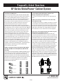
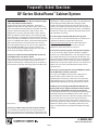
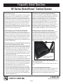
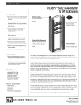
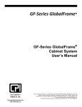
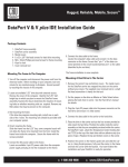
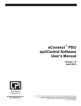
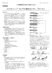
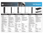
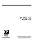
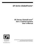
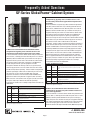
Frequently Asked Questions
GF-Series GlobalFrame® Cabinet System
Q. What is the recommended GF-Series GlobalFrame Cabinet
configuration for supporting servers and blade servers in a hot
aisle/cold aisle application that requires front-to-rear airflow?
A. CPI recommends a standard cabinet solution with perforated front
and rear doors, a solid top panel and solid side panels. Use a 23.6”W
(600 mm) cabinet to minimize floor space. Position the front pair of
equipment mounting rails to form an air dam with the cabinet frame.
The minimum cabinet frame depth should be 41.3”D (1050 mm) to
provide adequate internal space for equipment and cable
management. Remove the two large cable access port knockouts
from the top panel at the rear of the cabinet and cover with a Cable
Port Brush Kit (ordered separately). Include a Cable Lashing Bracket
(ordered separately) or similar vertical cable manager at the rear of
the cabinet for securing network and KVM cables that make
equipment connections. Use the included standard PDU Brackets
opposite the Cable Lashing Bracket to support vertical rack-mount
PDUs at the rear of the cabinet. Cover any open (unused) rack-mount
unit spaces with Snap-In Filler Panels (ordered separately).
Suggested part numbers for an example configuration are listed in the
table below:
Q. What is the recommended GF-Series GlobalFrame Cabinet
configuration for supporting servers and blade servers in a CPI
Passive Cooling® ducted exhaust application that requires front-totop airflow?
A. CPI recommends a high-density cabinet solution with perforated
front door, solid rear door with seal, a solid top panel with Vertical
Exhaust Duct, a Bottom Panel and solid side panels. Use a 23.6”W
(600 mm) cabinet to minimize floor space. Position the front pair of
equipment mounting rails to form an air dam with the cabinet frame.
The minimum cabinet frame depth should be 41.3”D (1050 mm) to
provide adequate internal space for capturing and guiding hot
exhaust air through the duct at the top of the cabinet. Remove the two
large cable access port knockouts from the top panel at the front of
the cabinet and cover with a Cable Port Brush Kit (ordered
separately). Include a Cable Lashing Bracket (ordered separately) or
similar vertical cable manager at the rear of the cabinet for securing
network and KVM cables that make equipment connections. Include
a Full Height PDU Bracket (ordered separately) opposite the Cable
Lashing Bracket to support vertical rack-mount PDUs and organize
power cables at the rear of the cabinet. Include an Airflow Director
(ordered separately) if per cabinet heat load exceeds 15 kW or if
there is equipment mounted in the bottom 5U of the cabinet. Cover
any open (unused) rack-mount unit spaces with Snap-In Filler Panels
(ordered separately). Suggested part numbers for an example
configuration are listed in the table below:
Quantity Part Number Description
1
GF-1A422
GF-Series GlobalFrame Cabinet, High-density, 42U,
79.3”H x 23.6”W x 47.2”D (2013 mm x 600 mm x 1200 mm),
Black
1
25221-701
Cable Lashing Bracket, 42U, 5”W (125 mm), Black
1
25141-700
Full Height PDU Bracket, 42U, 5.2”W (132 mm), Black
1
25190-001
Cable Port Brush Kit
1
25150-701
Airflow Director, for 23.6”W (600 mm) Cabinet, Black
2
TBD
CPI Vertical Power Strips or PDUs – matched to
site/equipment requirements
34537-001
Snap-In Filler Panel, 1U x 19”EIA, Pack of 6, Black
TBD
Note: If you use a wider cabinet, include Rail Seal Kit (P/N 25250-70x, 25252-70x) to cover cable
openings in the equipment mounting rails.
Quantity Part Number Description
1
GF-1A320
GF-Series GlobalFrame Cabinet, Standard Configuration, 42U,
79.3”H x 23.6”W x 41.3”D (2013 mm x 600 mm x 1050 mm),
Black
1
25221-701
Cable Lashing Bracket, 42U, 5”W (125 mm), Black
1
25190-001
Cable Port Brush Kit
2
TBD
CPI Vertical Power Strips or PDUs – matched to
site/equipment requirements
34537-001
Snap-In Filler Panel, 1U x 19”EIA, Pack of 6, Black
TBD
Note: If you use a wider cabinet, include Rail Seal Kit (P/N 25250-70x, 25252-70x) to cover cable
openings in the equipment mounting rails.
Q. What is the recommended GF-Series GlobalFrame Cabinet
configuration for supporting patch panels and fiber enclosures in a
cross connect application?
A. CPI recommends a standard cabinet solution with perforated front
and rear doors, a solid top panel and solid side panels. Use a 31.5”W
(800 mm) cabinet to provide addition internal space for managing
cables and patch cords. Position the front pair of equipment mounting
rails setback approximately 9.25” (235mm) into the cabinet to provide
space for managing patch cords at the front of the cabinet. The
minimum cabinet frame depth should be 39.4”D (1000 mm) to provide
+1-800-834-4969
www.chatsworth.com
Page 1
Frequently Asked Questions
GF-Series GlobalFrame® Cabinet System
adequate internal space for fiber enclosures and cable management.
Remove all four large cable access port knockouts from the top panel
and cover with Cable Port Brush Kits (ordered separately). Include
two Cable Lashing Brackets (ordered separately) or similar vertical
cable manager at the rear of the cabinet (one per side) for securing
network premise cables. Include two Vertical Cable Managers
(ordered separately) at the front of the cabinet (one per side) for
organizing patch cords. Suggested part numbers for an example
configuration are listed in the table below.
Quantity Part Number Description
1
GF-1C220
GF-Series GlobalFrame Cabinet, Standard Configuration, 42U,
79.3”H x 31.5”W x 39.4”D (2013 mm x 800 mm x 1000 mm),
Black
2
25221-702
Cable Lashing Bracket, 42U, 10”W (250 mm), Black
2
25120-706
Vertical Cable Manager with Extended Fingers,
42U, for 31.5” (800 mm) Cabinet, Black
2
25190-001
Cable Port Brush Kit
Q. Which cabinets (part numbers) are stocked for immediate
shipment?
A. Select cabinet part numbers and accessories are stocked
regionally for immediate shipment. These items can be shipped within
24 hours reducing delivery times as compared to items that are builtto-order. For a list of products available in each region, refer to the
immediate availability lists linked on the GlobalFrame webpage:
www.chatsworth.com/globalframe.
Q. Will CPI install accessories in GF-Series GlobalFrame Cabinets?
A. CPI can install certain accessories in GlobalFrame Cabinets prior
to shipping the cabinet, but this service only applies to build-to-order
cabinets shipped in standard lead times, not stocked cabinets and
accessories shipped within 24 hours. To order a cabinet with
accessories installed, you must configure a GlobalFrame Cabinet
(select the cabinet and accessories) using the on-line CPI Product
Configurator for Cabinet and Enclosure Systems:
www.chatsworth.com/configurator. There is a notes section to
designate your specific requirements like spacing of equipment rails.
The configured product will be assigned a CP part number and the
price will include a fee for installing accessories.
Q. What vertical cable management options are available?
A. The GF-Series GlobalFrame Cabinet System offers three types of
vertical cable managers: the Vertical Cable Manager, the Cable Ring
Kit/Cable Ring Manager and the Cable Lashing Bracket Kit.
• The Vertical Cable Managers (P/Ns 25110-7XX, 25120-7XX, 254047XX) attach to the cabinet’s equipment mounting rails and feature
plastic T-shaped cable management fingers that project in front of
the rails. Openings between the T-shaped fingers align with each
rack-mount unit (U) in the cabinet allowing cables to be organized
by rack-mount unit (U). Models for 29.5” (750 mm) and 31.5” (800
mm) wide cabinets feature standard or extended fingers, include a
door/cover and provide the largest amount of space for storing
cables. Use this enhanced manager to organize high density cabling
like patch and equipment cords for network switches, patch panels
or servers with many network connections.
• The Cable Ring Kits (P/Ns 25104-001, 25105-00X, 25106-00X) and
Cable Ring Managers (P/Ns 25103-7XX, 25102-7XX) include plastic
snap on D-rings that allow cables to be loosely bundled while
making it easier to add or remove cables as compared to cables
bundled with Saf-T-Grips or tie wraps. Each Cable Ring Kit includes
rings that attach directly to the cabinet’s equipment mounting rail.
Each Cable Ring Manager includes rings mounted on separate halfheight mounting brackets that attach to the cabinet’s frame and
move independent of the equipment mounting rails allowing them to
be positioned anywhere about the depth of the cabinet. The Cable
Rings for 29.5”W (750 mm) and 31.5”W (800 mm) cabinets are
available in two depths; medium and large. Cable Rings support the
best practice of loose bundling and are suitable for all medium
density cable management requirements.
• The Cable Lashing Bracket Kit (P/N 25221-7XX) includes two halfheight mounting brackets that attach to the cabinet’s frame and
move independent of the equipment mounting rails allowing them to
be positioned anywhere about the depth of the cabinet. The
brackets feature U-shaped tie points to secure cable bundles with
Saf-T-Grip Straps or cable ties. Cable Lashing Bracket Kit provides a
basic solution for securing multiple cable bundles and is best used
for low or medium density cabling where cabling will rarely change.
Q. How many cables will each cable manager hold?
A. It depends on the usable space within the manager, the size of the
cable and how/if cables are bundled. Download the CPI Cable Fill
Table at www.chatsworth.com/cablefill to compare recommended
cable fill values for all CPI cable managers.
Q. What is the CPI Cable Fill Table?
A. The CPI Cable Fill Table is a spreadsheet that estimates maximum
loose cable fill for all CPI cable managers. Cable fill is calculated by
dividing the area of the internal cross section of a cable manager by
the area of a single cable and reducing the value by 50% to allow for
gaps between the cables. You can enter the diameter of the cable
and a fill ratio for the manager. The table also lists the usable cable
fill area of each cable manager if you use a different method to
estimate cable fill. Download the CPI Cable Fill Table at
www.chatsworth.com/cablefill.
+1-800-834-4969
www.chatsworth.com
Page 2
Frequently Asked Questions
GF-Series GlobalFrame® Cabinet System
Q. Why are there different amounts of cable storage space for each
of the Vertical Cable Managers?
A. The Vertical Cable Managers (P/N 25110-7XX, 25120-7XX, 254047XX) are sized to match the width of the cabinets and have different
cross-sections providing different amounts of storage space for
cables. The managers attach to the side of the equipment mounting
rails inside the cabinet and create a vertical cable management
space along the side of the equipment mounting rails that is bound by
the rail and the side of the cabinet. All managers have plastic Tshaped cable management fingers that project in front of the
equipment mounting rails. Openings between the T-shaped fingers
align with each rack-mount unit (U) on the rails allowing cables to exit
the cable manager at each rack-mount unit (U). For the 23.6” (600 mm)
wide cabinet, the manager is simply the T-shaped cable management
fingers. There are tie points on the side of the manager to secure
cables with Saf-T-Grip® Straps or cable ties, but the cable storage
space is limited because there is only a small amount of space
between the equipment mounting rails and the cabinet’s side panels.
For the 29.5”W (750 mm) and 31.5”W (800 mm) cabinets, the managers
include optional door/covers which are supported by brackets offset
from the rails near the side panels. When the covers are used, the
internal space for cables is bound by the T-shaped fingers and the
brackets that support the cover. Additionally, the fingers on the
managers for 29.5”W (750 mm) and 31.5”W (800 mm) cabinets are
available in standard and nd extended lengths. The extended length is
approximately 2.5” (64 mm) longer, providing additional depth
(cross-section) for storing cables.
Q. What is the difference between Cable Ring Kits (P/N 25104-001,
25105-00X, 25106-00X) and Cable Ring Managers (P/N 25103-70X,
25102-70X)?
A. Each Cable Ring Kit (P/N 25104-001, 25105-00X, 25106-00X) includes
eight plastic D-rings that attach directly to the equipment mounting
rails in the cabinet. The rings snap onto the rails; no tools are
required for installation. Each Cable Ring Manager (P/N 25103-70X,
25102-70X) includes eight plastic D-rings and two half-height brackets
that attach to the cabinet frame independent of the equipment
mounting rails. The Cable Ring Manager can be located at any
location about the depth of the
cabinet.
Q. Are the different width Cable Ring Kits or Vertical Cable
Managers compatible with all cabinet widths?
A. No, there are specific part numbers for each cabinet width and
height.
Q. What is the maximum cable bundle size on the cable lashing
bracket (P/Ns 25221-70X)?
A. The Cable Lashing Bracket is available in two widths: 5” (125 mm)
and 10” (250 mm). The 5”W (125 mm) bracket is designed to accept
two 2.25” (57.2 mm) diameter round cable bundles and the 10”W (250
mm) bracket is designed to accept three 3” (76 mm) diameter round
cable bundles. Cable bundle sizes should be limited as required to
prevent blocked access to or airflow from rack-mount equipment.
Q. How large is the rectangular knockout in the cabinet’s top panel,
the Bottom Panel and the Brush Side Panel?
A. The GF-Series GlobalFrame design uses a universally sized
rectangular opening/knockout and brush cable access grommet in all
top panels, bottom panels, and side panels. See the image of the top
panel below for details. The rectangular opening /knockout is 4.5”W x
9”D (114 mm x 228 mm) with a single 4.7” (119 mm) diameter opening
punched through the center for large power plugs. The two-piece
brush cable access grommet that covers the opening provides a
slightly smaller 3.9”W x 8.8”D (99 mm x 224 mm) brush sealed opening
for cables. On the Bottom Panel (P/N 25130-7XX) and Brush Side
Panel (P/N 25037-7XX), the rectangular knockout is removed and the
opening is covered by a brush cable access grommet. On the top
panel, the rectangular opening is a knockout that includes two
smaller round 3.0” (76 mm) diameter knockouts. One of the round
knockouts is removed and includes a 2.8” (71 mm) diameter grommet.
Multiple knockouts allow users to configure the top panel to match
cabling requirements. The brush cable access grommet is ordered
separately as a Cable Port Brush Kit (P/N 35190-001). Additional round
grommets are ordered separately as a Cable Port Grommet Kit (P/N
35021-000). Download the CPI Cable Fill Table at
25104-001
25105-001
25106-001
25103-70X
25102-70X
+1-800-834-4969
www.chatsworth.com
Page 3
Frequently Asked Questions
GF-Series GlobalFrame® Cabinet System
www.chatsworth.com/cablefill for recommended cable fill values.
Q. Can the GF-Series Global Frame Cabinet be configured to support
side-to-side airflow for network switches?
A. Only in low-density, low power applications. The GF-Series
GlobalFrame Cabinet does not fully support network switches with
side-to-side airflow. Restricted airflow and uncontrolled recirculation
inside the cabinet will not allow larger network switches to be
deployed. These restrictions only allow smaller switches with low
power consumption and airflow demands to be installed. For higher
density applications, recommend the N-Series TeraFrame® Network
Cabinet. To configure the GlobalFrame cabinet for side-to-side airflow,
select a 31.5” (800 mm) wide cabinet, use the Rail Seal Kit (P/N 252527XX) to seal the openings in the mounting rails on one side at the
front and the opposite side at the rear and use Snap-In Filler Panels
(P/Ns 34537-000, 34538-000) to cover any open rack-mount unit
spaces on the front pair of equipment mounting rails. This creates a
partial side-to-side cold/hot airflow pathway.
Q. Can you use a Brush Side Panel (P/N 25037-7XX) and solid side
panel together on the same side of a cabinet?
A. Yes, the side panels are half height. You can mix a solid and brush
side panel on one side of the cabinet. Note that cabinets can be
bayed with solid side panels installed (side panel-to-side panel), but
you must omit one side panel when baying cabinets with Brush Side
baying cabinets spaced for 24” floor tiles, there will be an
approximate .4” (10 mm) gap between cabinets. You should fill the gap
with the Baying Seal Kit (P/N 25242-7XX). The Baying Seal Kit
includes seal strips that cover the gap at the front and rear of the
cabinets. Use one Baying Seal Kit if both cabinets have side panels. If
you omit side panels on both or either cabinet, order a second Baying
Seal Kit and cut it to length as required to fill the horizontal gap at the
top and bottom of the cabinets.
Q. Can the cabinet be ordered without doors and a top panel?
A. Yes, the cabinet can be ordered without doors and a top panel as a
standard part number. Use the CPI Product Configurator
(www.chatsworth.com/configurator) for Cabinet and Enclosure
Systems, GlobalFrame Cabinet System to select a GF-Series
GlobalFrame cabinet without doors or a top panel.
Q. Are service parts (doors, top panel, side panels) sold separately?
A. Yes, all service parts (doors, top panel, side panels, equipment
mounting rails, standard PDU brackets, caster kit, baying kit, leveling
feet, and floor mounting kit) are sold separately. To order doors, top
panel, side panels or equipment mounting rails, you need to know the
cabinet part number or size. The cabinet part number is printed on a
label located on the top frame support at the rear of the cabinet. If the
label is missing or unclear, provide overall measurements for the
replacement part.
Q. Do I need a special baying kit to center 23.6”W (600 mm) cabinets
over 24”W (610 mm) raised access floor tiles?
A. No, each 23.6”W (600 mm) cabinet includes a baying kit. The
baying kit will bay cabinets side-by-side or space cabinets
approximately .4” (10 mm) apart so that they can be centered over
24”W (610 mm) raised access floor tiles. Order the Baying Seal Kit
(P/N 25242-7XX) separately to cover the gap between the cabinets.
Panels (brush side panel-to-no side panel).
Q. Can you bay cabinets side-by-side with side panels installed?
A. Yes, Cabinets with solid side panels can be bayed side by side.
When using cabinets with brush side panels, you must omit one side
panel to provide clearance for the brush bezels. Note that if you are
Q. When do you use a Baying Seal Kit (P/N 25242-7XX)? Does the
Baying Seal Kit create a complete seal between cabinets allowing
side panels to be omitted without concern for escaping hot air?
A. Use the Baying Seal Kit to cover the approximate .4”W (10 mm) gap
left between two bayed 23.6”W (600 mm) cabinets when centered
over 24”W (610 mm) raised access floor tiles. The Baying Seal Kit only
covers the gap at the front and rear of the cabinet. For the best
performance, install side panels on both cabinets to prevent hot air
from escaping between the cabinets. However, if you omit side panels
between the cabinets, order a second Baying Seal Kit and cut the
pieces as required to fill the gaps betweem the bottom of the bayed
cabinets.
+1-800-834-4969
www.chatsworth.com
Page 4
Frequently Asked Questions
GF-Series GlobalFrame® Cabinet System
Q. Are covers for the cable knockouts in the cabinet’s top panel
included with the cabinet?
A. Four 2.8” (71 mm) diameter round grommets are factory installed in
the top panel, one per corner. Additional covers must be ordered
separately. There are two types of knockouts on the top panels: 2.8”
(71 mm) diameter round knockouts and 4.5”W x 9.0”D (114 mm x 228
mm) rectangular knockouts. The round knockouts are captive within
the larger rectangular knockouts. Order the Cable Port Grommet Kit
(P/N 35021-000) to cover the round knockouts and order the Cable
Port Brush Kit (P/N 25190-001) to cover the rectangular knockouts.
The standard and fan top panels have four knockouts, one per corner.
The Vertical Exhaust Duct top panel has two knockouts, front corners
only. Each kit includes two grommets/covers.
Q. What is the difference between Rail Seal Kit (P/N 25250-70X,
25252-70X) and Snap-In Grommet & Plug Kit (P/N 25108-001)?
A. Both kits are used with the 29.5”W (750 mm) and 31.5”W (800 mm)
cabinets. The Rail Seal Kit (P/N 25250-70X, 25252-70X) seals all of the
openings in the equipment mounting rails and the small space
between the rails and the side panel. You can use Vertical Cable
Manager (P/N 25120-70X, 25404-70X) with Rail Seal Kit, but not the
Cable Ring Kit (P/N 25105-00X, 25106-00X). The Snap-In Grommet &
Plug Kit (P/N 25108-001) only covers the large rectangular cable
openings in the equipment mounting rails, not the mounting holes for
the Cable Ring Kit or the small space between the equipment
mounting rails and the side panels. However, you can use Cable Ring
Kit (P/N 25105-00X, 25106-00X) with Snap-In Grommet & Plug Kit.
Q. When should you use an Airflow Director (P/N 25150-70X)?
A. Use the Airflow Director in a cabinet with a high heat load
(>15 kW) that has a Vertical Exhaust Duct top panel. Airflow Director
redirects horizontal exhaust airflow from servers mounted near the
bottom of the cabinet towards the Vertical Exhaust Duct at the top of
the cabinet. Note that a Bottom Panel (P/N 25130-7XX) is included
with cabinets that have a Vertical Exhaust Duct top panel. Do not
remove the Bottom Panel from the cabinet. The Airflow Director will
install over the Bottom Panel.
Q. When should you use a Bottom Panel (P/N 25130-7XX)?
A. The Bottom Panel (P/N 25130-7XX) is included with cabinets that
have a Vertical Exhaust Duct top panel, but it can be ordered
separately and added to standard GF-Series GlobalFrame Cabinets
also. GlobalFrame Cabinet includes casters and leveling feet that
elevate the cabinet above the floor. The bottom panel prevents airflow
through the bottom of the cabinet minimizing bypass airflow and hot
spots. Use it on standard cabinets to help maintain front-to-rear
airflow through the cabinet.
Q. How do you create an air dam to block front/rear airflow around
sides of rack-mount equipment inside the cabinet?
A. There are three ways to create an air dam inside the cabinet: with
the equipment mounting rails, with the Snap-In Grommet & Plug Kit
(P/N 25108-001) or with the Rail Seal Kit (P/N 25250-70X, 25252-70X).
• The equipment mounting rails in the GlobalFrame Cabinet are
z-shaped. If you locate the equipment mounting rails within 2” (51
mm) of maximum depth in the 23.6”W (600 mm) cabinets so that the
z-shape overlaps the cabinet frame, the rails will form an air dam
along the sides of the cabinet.
• The equipment mounting rails on 29.5”W (750 mm) and 31.5”W (800
mm) cabinets have seven 5.5”H x 3.25”W (140 mm x 83 mm)
rectangular openings. The Snap-In Grommet & Plug Kit (P/N 25108001) includes 14 snap-in plastic grommets and covers that seal the
rectangular openings in the rails forming a partial air dam along the
sides of the cabinet. Note that the holes for attaching Cable Rings
will not be covered so you can use the Cable Ring Kit (P/N 2510500X, 25106-00X) with the Snap-In Grommet & Plug Kit.
• The Rail Seal Kit (P/N 25250-70X, 25252-70X) has four half-height
panels that attach to the equipment mounting rails in 29.5”W (700
mm) and 31.5”W (800 mm) cabinets and completely cover all of the
openings in the rails and the small space between the rails and the
cabinet’s side panels. Cable Ring Kit (P/N 25105-00X, 25106-00X)
cannot be used with the Rail Seal Kit, but Vertical Cable Manager
(P/N 25120-70X, 25404-70X) can.
Rear view of GF-Series GlobalFrame
Cabinet with Airflow Director and
Bottom Panel installed.
Q. Can the bottom panel be used as a shelf? If so, what is the load
rating of the bottom panel?
A. No, the bottom panel is not load rated and should not be used as a
shelf.
Q. Can the cabinet support rack-mount shelves?
A. Yes, single-sided 19”EIA rack-mount shelves and 19”EIA four-post
(cabinet) shelves can be mounted in the cabinet when there is
sufficient rack-mount space and depth for the shelf and the cabinet’s
equipment mounting rails are positioned to support the shelf.
+1-800-834-4969
www.chatsworth.com
Page 5
Frequently Asked Questions
GF-Series GlobalFrame® Cabinet System
Q. Does CPI offer shelves for cabinets?
A. Yes, CPI offers several shelves for cabinets with load bearing
capacities ranging from 100 lb (45.4 kg) to 300 lb (136.1 kg). The Low
Profile Fixed Shelf (P/N 12573-719) is a good general purpose shelf. It
is 1U, 19”EIA, with a telescoping design that extends 20”-36” deep
(510-910 mm) and holds 100 lb (45.4 kg) of equipment.
Q. What is the difference between the standard PDU brackets and
the full height PDU bracket?
A. The standard PDU brackets are two L-shaped brackets that attach
to the cabinet frame in a fixed position and locate PDUs in the rear
corner of the cabinet with outlets facing the center of the cabinet.
Standard PDU brackets will support up to two 2.0”W (51 mm) or
narrower CPI Vertical Power Strips or PDUs for cabinets or one
4.5”W (114 mm) PDU and require a 5.9” (150 mm) mounting rail
setback. The Full Height PDU bracket attaches to the side of the
cabinet frame at any location about the depth of the cabinet. Full
Height PDU brackets support up to two 2.4”W (61 mm) or narrower
CPI Vertical Power Strips or PDUs for cabinets or one 4.9”W (124 mm)
PDU. Full Height PDU bracket is 5.2” (132 mm) wide and has tie points
along the sides for securing bundled power cords with Saf-T-Grip®
Straps or tie wraps. The Full Height PDU Bracket requires a minimum
7.5” (191 mm) mounting rail setback in 23.6”W (600 mm) cabinet and a
minimum of 7.25” (185 mm) mounting rail setback in 29.5”W (750 mm)
and 31.5”W (800 mm) cabinets to provide clearance for PDUs. The Full
Height PDU Bracket must be used when PDUs are installed in
cabinets that will be shipped on shock pallets.
Q. Can any tool-less PDU attach to the standard PDU brackets and
the Full Height PDU Bracket?
A. No, only vertical PDUs with tool-less attachment points located
64.75” (1645) or 61.25” (1556 mm) apart will attach to the brackets. All
CPI Vertical Power Strips and PDUs for cabinets will attach to the
brackets. Competitor PDUs may have different tool-less attachment
point spacing. Note that the Standard PDU Brackets support either
64.75" (1645 mm) or 61.25" (1556 mm) tool-less attachment points, not
both, depending on where they are mounted on the cabinet frame.
Full Height PDU Bracket supports both. Use Full Height PDU Bracket if
you have a mix of PDUs or if you do not know the PDU's tool-less
spacing requirements.
Q. When do I select shock pallet packaging?
A. Select shock pallet packaging if you want to load the cabinet with
equipment in one facility and then reship the cabinet to another
facility preconfigured for quicker installation. Shock pallet packaging
includes a special pallet designed to support a cabinet loaded with up
to 2,000 lb (907.2 kg) of equipment, a reusable cardboard carton to
protect the cabinet and a wooden unloading ramp.
Q. Can you attach cable runway to the top of the GF-Series
GlobalFrame cabinet?
A. Yes, the top panel is punched with attachment points for 12”W (300
mm) cable runway at the front and the rear of the cabinet. Attach
cable runway to the cabinet’s top panel in parallel (side-to-side)
orientation using the Cable Runway Elevation Kit for cabinets (P/N
10506-712, 10506-716). Remove and match drill the top panel to attach
other cable runway sizes.
Q. Why are there three load capacities listed for the GF-Series
GlobalFrame cabinet?
A. The three load capacities stated for the GF-Series GlobalFrame
cabinet are the static load, the rolling load and the shipping load. The
3,000 lb (1360 kg) static load is the maximum load when the cabinet is
supported on leveling feet and secured to the floor. The 2,250 lb (1020
kg) rolling load is the maximum load on casters. The 2,000 lb (907.2 kg)
shipping load is the maximum load of installed equipment when
shipped on the shock pallet. Be sure to apply the correct load limit
per your application.
Q. The load rating on casters is less than the static load rating on
leveling feet. Do casters have to be removed to achieve the full
static load rating?
A. No, simply extend the leveling feet to raise the cabinet so the
wheels on the casters spin freely.
Q. How do you adjust the leveling feet on GF-Series GlobalFrame
cabinet?
A. The leveling feet are mounted to a threshold at the base of the
cabinet. They can be accessed by opening the cabinet doors and
adjusted up or down from the top with a screwdriver. Alternately, you
can access the feet from under the cabinet frame and adjust them up
or down with a wrench when the cabinet is heavily loaded.
Q. Does the side panel latch interfere with cable management
accessories?
A. The side panel latch is located at the center of the side panel and
connects to the cabinet frame near the middle of the cabinet’s side.
Cable management accessories attach to the cabinet frame, but the
side panel latch will not interfere with cable management
accessories that are located near the corners of the cabinet.
Q. Are there other door styles available for the GF-Series
GlobalFrame cabinet?
A. No, three door styles are available in two configurations:
perforated front and double perforated rear doors on the standard
cabinet to support front-to-rear airflow and perforated front and solid
rear doors on the high density cabinet to support front-to-top airflow.
+1-800-834-4969
www.chatsworth.com
Page 6
Frequently Asked Questions
GF-Series GlobalFrame® Cabinet System
Q. I did not find the answer to my question. Who do I contact for
assistance?
A. Please contact CPI Technical Support (800-834-4969 or
[email protected]) for assistance.
Q. Can the top panel be removed from the cabinet?
A. Yes, the top panel is a single-piece solid panel that features toolless removal. After removing two screws that secure the top panel
during shipping, two push pins secure the top panel onto the cabinet
frame.
Q. Can cables enter the bottom of the cabinet?
A. Yes, the bottom of the cabinet is open on standard cabinets. The
Bottom Panel is included on high density cabinets that have the
Vertical Exhaust Duct top panel. The Bottom Panel has one large
brush sealed rectangular cable access port for cables.
Q. Is equipment mounting hardware (rack-mount hardware) included
with the cabinet?
A. Yes, each cabinet includes 25 each M6 cage nuts and screws.
Additional equipment mounting hardware (P/N 12637-001) can be
ordered separately.
Q. Are leveling feet included with the cabinet?
A. Yes, the cabinet includes leveling feet. The cabinet ships with
leveling feet installed on the cabinet. To replace damaged or
misplaced leveling feet, order a GlobalFrame Cabinet Common Parts
Kit (P/N 25240-701)
Q. Are casters included with the cabinet?
A. Yes, casters are included with the cabinet. The cabinet ships with
casters installed on the cabinet. To replace damaged or misplaced
casters, order a GlobalFrame Cabinet Caster Kit (P/N 25230-001). Note
that overall heights listed in the product data sheet include the height
of casters. The 42U cabinet is 79.3”H (2013 mm) and will fit through a
standard 7’H (2.1 m) interior doorway which typically has an 83”H
(2108 mm) maximum clearance.
Q. Are floor attachment brackets included with the cabinet?
A. Yes, floor attachment brackets are included with the cabinet, but
floor installation hardware is not and must be ordered separately. The
brackets are L-shaped and attach to the bottom of the cabinet frame
at the front and rear of the cabinet. The brackets are used to secure
the cabinet to the shipping pallet. Order 3/8” or M10 floor installation
hardware separately to secure the brackets to the floor. To replace
damaged or misplaced floor attachment brackets, order the Floor
Mounting Kit (P/N 25171-001).
Q. I have questions about the assembly of components and/or
installation of the cabinet?
A. The GlobalFrame Cabinet System User Manual, which includes a
complete installation guide, is available for download on the CPI
Website at www.chatsworth.com/globalframe.
©2011 Chatsworth Products, Inc. All rights reserved. CPI, CPI Passive Cooling, MegaFrame, Saf-T-Grip, Seismic Frame,
SlimFrame, TeraFrame, GlobalFrame, Cube-iT Plus, Evolution, OnTrac, and QuadraRack are federally registered
trademarks of Chatsworth Products, Inc., Simply Efficient and Velocity are trademarks of Chatsworth Products, Inc.
All other trademarks belong to their respective companies Rev.3 08/11 MKT-60020-502
Page 7