1
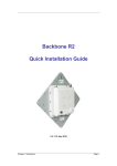
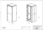
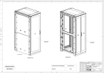
Z4-‐Series SeismicFrame® ® Z4-Series SeismicFrame Cabinet System User’s Manual While every effort has been made to ensure the accuracy of all information, CPI does not accept liability for any errors or omissions and reserves the right to change information and descriptions of listed services and products. [email protected] www.chatsworth.com ©2014 Chatsworth Products, Inc. All rights reserved. Chatsworth Products, CPI, CPI Passive Cooling, eConnect, MegaFrame, Saf-T-Grip, Seismic Frame, SlimFrame, TeraFrame, GlobalFrame, Cube-iT Plus, Evolution, OnTrac, QuadraRack and Velocity are federally registered trademarks of Chatsworth Products. Simply Efficient is a trademark of Chatsworth Products. All other trademarks belong to their respective companies. 07/14 MKT-60020-628 Contents Z4-‐Series SeismicFrame Cabinet Overview ......................................................................................... 3 Introduction to the Z4-‐Series SeismicFrame Cabinet ............................................................................. 3 Safety Information .................................................................................................................................. 3 Intended Use .......................................................................................................................................... 5 Components of the Z4-‐Series SeismicFrame Cabinet ............................................................................. 6 Included Hardware ................................................................................................................................. 7 Tools Required ........................................................................................................................................ 9 Unpacking ............................................................................................................................................... 9 Installation ....................................................................................................................................... 11 Moving the cabinet ............................................................................................................................... 11 Removing the casters ........................................................................................................................... 11 Anchoring the cabinet to the floor ....................................................................................................... 13 Bonding the cabinet to the telecommunications ground ..................................................................... 14 Configuring the cabinet .................................................................................................................... 16 Removing and Installing the Front Door ............................................................................................... 16 Removing and Installing the Rear Doors ............................................................................................... 18 Removing and Installing the Top Panel ................................................................................................. 19 Removing and Installing the Side Panels .............................................................................................. 22 Adjusting the Equipment Rails .............................................................................................................. 26 Installing Equipment ............................................................................................................................. 27 Cable Management .............................................................................................................................. 27 Accessories ...................................................................................................................................... 28 Cable Management .............................................................................................................................. 28 Thermal Management .......................................................................................................................... 29 Power Management ............................................................................................................................. 30 Shelves, Trays and other accessories .................................................................................................... 30 Z4-‐Series SeismicFrame® Cabinet Overview Introduction to the Z4-‐Series SeismicFrame® Cabinet The Z4-‐Series SeismicFrame Cabinet System from Chatsworth Products, Inc. (CPI) has been developed to meet a range of seismic application needs. The Z4-‐Series SeismicFrame is available in two widths, two heights, and two depths, allowing for alignment with the size and capacity requirements for most installations. The Z4-‐Series SeismicFrame cabinet accessories, including cable management, power management, thermal management and more, offer additional flexibility, enabling the cabinet to be further configured to support many different applications. Safety Information Keep a printed copy of this User’s Manual, especially the following safety information, in or near the cabinet. WARNINGS: • Improper use of this product or failure to follow these instructions may result in equipment damage, personal injury, or death. Read and understand all instructions for proper installation and use of this product. • Only trained service personnel or licensed electricians shall install the equipment. • Be sure to use sufficient personnel to safely remove the cabinet from the pallet. • Do not attempt to move large cabinets by yourself. Obtain adequate assistance to stabilize the cabinet during movement or hire professional equipment riggers. • Move cabinets on installed casters with extreme care. Sudden stops, excessive force, and uneven surfaces may cause the cabinet to overturn. Move the cabinet with the back as the leading edge. Never push on the sides. • The cabinet shall be level, stable, bolted and appropriately secured to the building structure. Castors are only provided to transport the cabinet from the receiving location to its install location. • The cabinet shall be installed in a Restricted Access Location and only used by trained service personnel. • Suitable for mounting on concrete or other noncombustible surface only. 3 Safety Information WARNINGS: • Unload equipment from the cabinet before moving it. • Two or more cabinets can be bayed together (coupled) to enhance their stability. Each cabinet should be anchored to the floor. • Before loading equipment in the cabinet, always anchor the cabinet frame to the floor. • Always load heavy equipment, such as a UPS, at the bottom of the cabinet first, and add lighter equipment on higher levels. • A safety risk exists when equipment is mounted on a shelf installed more than 30 inches (760 mm) above the floor in a cabinet without doors and/or side panels. The equipment may accidentally slide or be accidentally pushed off the shelf and fall on personnel. When equipment is mounted on a shelf, securely fasten the equipment to the shelf or cabinet frame in a manner that will prevent the equipment from accidentally sliding off the shelf. The following accessories may be used to secure certain equipment on shelves: monitor tie-‐down kit (P/N 11725-‐701), seismic equipment tie-‐down bracket (P/N 14061-‐719), or equipment tie-‐down bracket (P/N 16356-‐719). • The cabinet can support many system configurations. The amount of force required to tip or make the cabinet unstable differs with each. Read and follow your equipment manufacturer’s specific assembly, installation, and safety instructions. • When servicing slide-‐mounted equipment such as servers: - Secure all equipment, other than the unit being serviced, in position to prevent it from sliding out and destabilizing the cabinet. - Slowly extend only one unit at a time. Extending multiple units may cause the cabinet to tip over. Rapid deployment of the unit could cause the cabinet to tip. • For protection of the equipment and personnel, ground each cabinet individually to the Telecommunications Equipment Bonding Conductor (TEBC) or Signal Reference Structure (SRS). • Provide the minimum spacing between the accessories/components and the housing that shall be maintained for safe operation of the equipment when installed in accordance with the National Electric Code, ANSI/NFPA 70. • As appropriate, all wiring and equipment should be installed in accordance with NFPA 70, “National Electrical Code,” and the applicable sections of ANSI C2, “National Electrical Safety Code." 4 Intended Use Keep a printed copy of the Preface of this User’s Manual in or near the cabinet. • Install the cabinet only in a Restricted Access Location, such as a data center. • Use indoors only, in environmentally controlled areas; do not use outdoors, in harsh environments, or in air-‐handling spaces. • Use the cabinet for information technology and telecommunications equipment, including servers and peripherals. • Allow only qualified service personnel to use the cabinet. • The cabinets must be anchored to the floor to ensure stability and a safe working environment. • The load-‐bearing capacity of the Z4-‐Series SeismicFrame Cabinet is: Static: 3,000 lb (1360 kg)* Seismic: 1,500 lb (680 kg)** *Tested to UL 2416, Issue 2, July 2013 Section 11.1.4, Loading test (4X rated load) **Tested to Telcordia Technologies GR-‐63-‐CORE, Issue 4, April 2012, Sections 4.4 5 Components of the Z4-‐Series SeismicFrame Cabinet 1. Frame 4. Side panel 2. Front door 5. Double rear door 3. Equipment mounting rails 6. Standard top panel 6 Included Hardware 1. (2) Keys x 2 2. (50) M6 Cage Nuts and Screws x 50 x 50 3. (2) Baying Brackets, (4) M8x20 Hex Head Screws, + (4) M8 Hex Nuts x 2 x 4 x 4 4. (1) Ground Terminal Block + (2) M5x16 Bolts + (2) M5 Hex Nuts + Antioxidant Compound x 1 x 2 x 2 7 5. (4) M8x90 Lag screws + (4) Wide Washers + (4) M8 Washers Used to secure the x 4 cabinet to the pallet during shipping. x 4 x 4 8 Getting Started Tools Required 1. 13 mm Socket Wrench a. b. c. d. For removing lag bolts securing cabinet to pallet For removing casters For adjusting equipment mounting rail For installing baying brackets 2. 8mm Socket or Open End Wrench a. For installing ground terminal block 3. #2 Phillips Screwdriver a. b. c. d. For removing dust cover to expose shipping lag bolts For installing M6 screws into cage nuts to secure equipment in mounting rails For removing and installing door hinges For installation and removal of PDU brackets 4. 5mm Ball Hex Driver a. For extending and retracting leveling feet Unpacking CAUTION: The Z4-‐Series SeismicFrame cabinet is heavy. Use a minimum of two (2) people to unpack and remove the cabinet from the pallet. CAUTION: The Z4-‐Series SeismicFrame casters are for moving the cabinet short distances over smooth floor surfaces only. Move shipping pallet as close as possible to the final installation location before unpacking. CAUTION: The Z4-‐Series SeismicFrame casters and levelers are not intended to support cabinet loads for extended periods of time. Always anchor the cabinet after positioning. 9 Inspect the cabinet for damage. If any damage to the cabinet is observed, contact your distributor or CPI Customer Service. 1. Carefully remove the cardboard wrap surrounding the cabinet. 2. Remove the four (4) cardboard corner protectors and bag. 3. Inspect inside the cabinet to insure all items are securely fastened to the cabinet. Remove any items that were shipped inside the cabinet but are not fastened to the cabinet. 4. Remove the (2) bottom dust covers to expose the lag bolts that attach the cabinet to the pallet using a #2 Phillips Screwdriver. 5. Remove the (4) lag bolts that hold the cabinet to the pallet using a 13 mm (1/2”) socket wrench. 6. Remove the cabinet from the pallet. RECYCLABLE MATERIALS: CPI uses only recyclable materials in all of its cabinet packaging. Please save packaging for later use or dispose of properly. All wood components of CPI pallets have been properly treated to comply with the pest-‐free certifications required by foreign countries. 7. If the cabinet is to be reshipped, save all packaging materials for reuse. DISCLAIMER: CPI is not responsible for any damage to the cabinet or its contents after the cabinet is repackaged and reshipped. 8. After the cabinet is unpacked, check the cabinet and the hardware kit to insure that all of the components and hardware items have been received with the cabinet. If any components are missing or damaged, email Technical Support at [email protected], or call toll-‐free at 800-‐834-‐4969 (US & Canada) Monday to Friday, 5 a.m. to 5 p.m., Pacific Time. 10 Installation Moving the cabinet CAUTION: The Z4-‐Series SeismicFrame Cabinet ships on casters. Move the cabinet by pushing on the front or the rear of the cabinet. Do not push the cabinet from the sides. The Z4-‐Series SeismicFrame cabinet has been provided with four (4) casters to allow the cabinet to be rolled into position. Once the cabinet has been moved to the final location, remove the casters and fully recess the levelers per the instructions below. Removing the casters Lower all four (4) levelers using a 5mm ball hex driver until casters are slightly raised. 5mm Ball Hex Driver Access 11 If you don’t have a 5mm Ball Hex Driver you can use a wrench on the bottom of the leveler. Next, using a 13mm Socket Wrench, remove single M8 screw from each (4) caster bracket. Lift caster bracket up and back to remove. 13mm Socket Wrench Once casters are removed, fully recess each leveler, lowering the cabinet until it sits on the floor. Levelers are only used for ease of removing casters. Cabinet must sit directly on floor for anchoring. 12 Anchoring the cabinet to the floor Insure the casters have been removed and all levelers recessed. Z4-‐Series SeismicFrame Cabinets, whether bayed together or standing alone, should be anchored to the floor. The recommended anchor to use is Hilti HSL-‐3 M12/50 or use hardware appropriate for your type of flooring as determined by your EOR. Follow anchor manufacturer’s installation instructions for floor preparation. Anchor cabinet in two (2) locations in the front and two (2) locations in the rear of the cabinet. Anchorage holes Anchor Locations 13 Bonding the cabinet to the telecommunications ground Z4-‐Series SeismicFrame Cabinets should be bonded to the telecommunications ground. The top panel, side panels, doors and mounting rails on the Z4-‐Series SeismicFrame cabinet are electrically bonded to the frame. A ground strap bonds the side panels and doors to the frame. Nibs screws bond the top panel to the frame. In order to bond the cabinet to the telecommunications ground, use the Ground Terminal Block (included) to connect a bonding conductor to the telecommunications ground or signal reference grid. Remove the mask sticker at desired grounding location and apply generous coating of gray antioxidant. Secure grounding wire to the terminal block. Attach the block to the cabinet frame with an 8 mm wrench using two M5 bolts and nuts. 14 Baying cabinets together Z4-‐Series SeismicFrame Cabinets can be bayed (fastened) together with solid side panels in place or with no side panels, depending on installation requirements. Cabinets must be the same height and depth. 1. Remove the hole plugs on top of cabinet frame. 2. Use the supplied hardware and a 13mm Socket wrench to attach the baying bracket (included in the hardware kit) to the first cabinet. Make sure to use the correct set of holes for the desired cabinet spacing (24” or 600 mm). The 24” spacing will center two 600 mm wide cabinets over a 24” access floor tile – spaces cabinets approximately 0.4” (10 mm) apart. The 600 mm spacing will bay any two cabinets side-‐by-‐side. 24” Spacing 600mm Spacing 3. Move the second cabinet so that the cabinets are aligned. 4. Use the supplied hardware to attach the baying bracket to the second cabinet. 5. Repeat steps 1-‐4 for the other end of the cabinet. 15 Configuring the cabinet The Z4-‐Series SeismicFrame Cabinet can easily be configured for a variety of applications. Not only can the standard cabinet components be adjusted or removed, but a broad range of accessories can be installed to create a cabinet solution that meets all the needs of your installation requirements. Removing and Installing the Front Door CAUTION: To avoid personal injury and reduce the risk of damaging the door or the cabinet, one person should support the door while another person retracts the hinge pins and removes the door from the frame. Removing the Front Door: 1. Open the front door to 90 degrees so that it is perpendicular to the cabinet. The door is perpendicular to the cabinet when it is parallel with the side of the cabinet. 2. Disconnect the ground wire. 3. While supporting the door, retract the hinge pin from the lower hinge. Note: the door, hinge pin and/or hinge may be damaged if the door is not properly supported while being removed. Hold the door so that it does not lean. 4. Retract pin from upper hinge. Support the door while lifting and moving the door. Once the door is free of the hinges, move the door away from the frame. 3. Retract pin 2. Disconnect wire 4. Retract pin 16 Installing the Front Door: 1. Hold the door so that it is perpendicular to the cabinet and align the hinge pins on the door with the hinge barrels on the cabinet. The door is perpendicular to the cabinet when it is parallel with the side of the cabinet. 2. Align the upper hinge pin with the upper hinge barrel. Insert the upper hinge pin into the upper hinge barrel. Continue to support the door, keeping it vertical and perpendicular to the cabinet frame. The door must be supported to prevent damage to the hinges. 3. While supporting the door, align the lower pin with the pin barrel and push pin down into place. Check that both hinge pins are inserted into the hinge barrels before releasing the door. 4. Reconnect the ground wire. 5. Close the front door. 3. Push pin down 2. Connect wire 2. Push pin up 17 Removing and Installing the Rear Doors Removing the Rear Doors: 1. With the doors closed, lift and remove the hinge pins from both the upper and lower hinges on the door that you want to remove. 2. Partially open the door, but not as far as 90 degrees. 3. Disconnect the ground wire. 4. Open the door to exactly 90 degrees and pull the door away from the cabinet frame. Installing the Rear Doors: 1. Hold the door in a 90 degree open position. 2. Align the hinges on the door with the hinges on the frame and slide the hinges together. 3. Rotate the door to the closed position. 4. Insert the hinge pins (from the top of the hinge) into both the upper and lower door hinges. 5. Open the door and reconnect the ground wire. 18 Removing and Installing the Top Panel Removing the Top Panel: 1. Open the rear door(s) of the cabinet. 2. Using a T30 Torx driver, remove the six (6) screws on the top panel. Two (2) are located on each side and two (2) on the rear of the top panel. Front of cabinet T30 Torx Driver Top panel Top rear lateral Slide 3. Push up on the top panel and remove. 19 Installing the Top Panel: 1. Align the front edge of the top panel with the frame. 2. Lower the top panel, sliding it forward to make contact with the front of the frame. Top Panel Cabinet Front Top Panel Front Top Lateral Top panel Hooks Top Lateral Slots 3. Lower the back of the top panel 20 4. Using a T30 Torx driver, install the six (6) screws on the top panel. Two (2) are located on each side and two (2) on the rear of the top panel. The screws ground the top panel to the frame. Front of cabinet T30 Torx Driver Top panel Top rear lateral Slide 21 Removing and Installing the Side Panels Removing the Side Panels: 1. Unlock the side panel latch with the key (if necessary). 2. Remove two (2) screws using 13mm socket wrench. 13mm Socket Wrench 22 3. Tilt side panel out and disconnect the ground wire. Disconnect ground wire 4. Lift up on the side panel and remove it from the cabinet. 23 Installing the Side Panels: 1. Align the side panel with the cabinet frame and slip the side panel into the side of the frame. Allow the side panel to move downwards so that the lip on the bottom of the panel engage the front-‐to-‐ rear frame member below the side panel. 2. Connect the ground wire. 13mm Socket Wrench Connect ground wire 24 3. Rotate the side panel up to meet the frame and push until side panel hits brackets. Install two (2) M8 hex screws using a 13mm socket wrench. 13mm Socket Wrench 4. Lock the side panel with the key (if necessary). 25 Adjusting the Equipment Rails 1. Use a 13 mm socket wrench to loosen (but do not remove) the nuts securing the equipment rail to the frame in nine (9) locations on the front rails or six (6) locations on the rear rails. 2. Move the equipment rail forward or backward to the desired location. 3. Tighten the nuts in all nine (9) locations on the front rails or six (6) locations on the rear rails. Markings are provided on the frame to help align the equipment rails so that they are vertical as well as in the same location as the rails on the opposite side of the frame. 26 Installing Equipment The Z4-‐Series SeismicFrame Cabinet supports all manufacturers’ equipment that conforms to the EIA/ECA-‐310E standard. Most equipment attaches directly to the equipment mounting rails; however, some manufacturers may provide brackets or slide assemblies that require additional installation. Rack-‐mount unit (U) markings are clearly printed on the equipment rails to simplify installation of components. Align equipment with the U markings on each side of the cabinet before securing the equipment. ü NOTE: Equipment rails should be adjusted to the desired location (front to rear) prior to installing equipment. See “Adjusting the Equipment Rails” on page 25. The Z4-‐Series SeismicFrame Cabinet is provided with hardware to secure equipment to the mounting rails. This hardware includes 50 sets of M6 cage nuts and screws. Additional hardware is available for purchase (see “Other Accessories” on page 30). Cable Management CPI cable management products provide the proper cable bend radii for better data transmission; fewer tangled cords and cable damage; and ease in moving, adding, and changing connections. The products assist in complying with ANSI/TIA/EIA installation of Category 5/5e/6/6a and fiber cables. Separate the cables by type, gather into bundles, and fasten loosely with hook and loop fasteners. CPI offers Saf-‐T-‐Grip Straps to fasten cable bundles (P/N 0200X-‐series). See “Accessories – Cable Management” on page 28 for more information. 27 Accessories Cable Management Ring Cable Manager, 600mm Cabinet For 23.6” (600 mm) wide cabinets Two (2) half-‐height sections Ring Cable Manager, 800mm Cabinet For 31.5” (800 mm) wide cabinets Two (2) half-‐height sections Cable Lashing Bracket Two (2) half-‐height panels Attaches to the cabinet frame 40U x 600 -‐ 14440-‐X00 43U x 600 -‐ 14440-‐X01 40U x 800 -‐ 14445-‐X00 43U x 800 -‐ 14445-‐X01 14440-XXX 14445-XXX 40U -‐ 14465-‐X00 43U -‐ 14465-‐X01 Front to Rear Cable Manager For 31.5” (800 mm) wide cabinets 14485-‐X00 X = Color (C=Black, E=Glacier White) 28 Thermal Management Air Dam For 23.6” (600 mm) wide and 31.5” (800 mm) wide cabinets 40U x 600 -‐ 14435-‐X00 43U x 600 -‐ 14435-‐X01 40U x 800 -‐ 14435-‐X02 43U x 800 -‐ 14435-‐X03 Baying Seal Kit Seals space between cabinets when bayed 24” apart 40U -‐ 39137-‐700 43U -‐ 39137-‐703 Snap-‐In Grommet & Plug Kit For 31.5” (800 mm) wide cabinets Set of 8 grommets that push into equipment rails 39133-‐001 Snap-‐In Filler Panel 1U X19, Black, 6 EA -‐ 34537-‐001 2U X19, Black, 6 EA -‐ 34538-‐001 1U X19, Black, 50 EA -‐ 34537-‐002 2U X19, Black, 50 EA -‐ 34538-‐002 1U X19, Glacier White, 6 EA -‐ 34537-‐E01 2U X19, Glacier White, 6 EA -‐ 34538-‐E01 1U X19, Glacier White, 50 EA -‐ 34537-‐E02 2U X19, Glacier White, 50 EA -‐ 34538-‐E02 X = Color (C=Black, E=Glacier White) 29 Power Management PDU brackets are available as well as a wide range of power strips and PDU’s, including monitored and switched versions. Full Height PDU Bracket Two sizes: Dual and Wide Attaches to the cabinet frame Dual support 2 x 2.2”W (51 mm) PDUs Wide support 2 x 2.7”W (69 mm) PDUs Dual, 4.8” (121 mm): 40U -‐ 14480-‐X00 43U -‐ 14480-‐X01 Wide, 5.8” (147 mm): 40U -‐ 14481-‐X00 43U -‐ 14481-‐X01 X = Color (C=Black, E=Glacier White) Shelves, Trays and other accessories Cage Nuts & Screws (25) M6 cage nuts and screws 12637-‐001 Low Profile Fixed Shelf 1U x 19”W Telescopes 20”-‐ 36” (510 mm -‐ 910 mm) in depth 12610-‐719 Seismic Equipment Bracket for Cabinets 1U x 19”W Adjusts 15”-‐32” (380 mm and 810 mm) in depth 14061-‐719 30