1
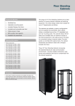
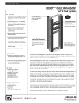
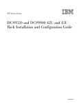
GF-‐Series GlobalFrame® GF-Series GlobalFrame® Cabinet System User’s Manual ©2011 Chatsworth Products, Inc. All rights reserved. CPI, CPI Passive Cooling, MegaFrame, Saf-T-Grip, Seismic Frame, SlimFrame, TeraFrame, GlobalFrame, Cube-iT Plus, Evolution, OnTrac, and QuadraRack are federally registered trademarks of Chatsworth Products, Inc., Simply Efficient and Velocity are trademarks of Chatsworth Products, Inc. All other trademarks belong to their respective companies.Rev.4 07/11 MKT-60020-503 [email protected] www.chatsworth.com Contents GlobalFrame Cabinet Overview .......................................................................................................... 3 Introduction to the GlobalFrame Cabinet ............................................................................................... 3 Safety Information .................................................................................................................................. 3 Intended Use .......................................................................................................................................... 5 Components of the GlobalFrame Cabinet .............................................................................................. 6 Included Hardware ................................................................................................................................. 7 Getting Started ................................................................................................................................... 8 Tools Required ........................................................................................................................................ 8 Unpacking ............................................................................................................................................... 8 Installation ....................................................................................................................................... 10 Moving the cabinet ............................................................................................................................... 10 Anchoring the cabinet to the floor ....................................................................................................... 10 Bonding the cabinet to the telecommunications ground ..................................................................... 11 Baying cabinets together ...................................................................................................................... 12 Configuring the cabinet .................................................................................................................... 13 Removing, Installing and Reversing the Front Door ............................................................................. 13 Removing and Installing the Rear Doors ............................................................................................... 14 Removing and Installing the Top Panel ................................................................................................. 15 Removing and Installing the Side Panels .............................................................................................. 17 Adjusting the Equipment Rails .............................................................................................................. 18 Installing the Standard PDU Brackets ................................................................................................... 18 Installing Equipment ............................................................................................................................. 19 Cable Management .............................................................................................................................. 19 Accessories ...................................................................................................................................... 20 Cable Management .............................................................................................................................. 20 Cable Management (cont’d) ................................................................................................................. 21 Power Management ............................................................................................................................. 22 Thermal Management .......................................................................................................................... 23 Shelves, Trays and other accessories .................................................................................................... 26 Service Parts ......................................................................................................................................... 27 GF-‐Series GlobalFrame Cabinet Overview Introduction to the GF-‐Series GlobalFrame Cabinet The GF-‐Series GlobalFrame® Cabinet System from Chatsworth Products, Inc. (CPI) has been developed to meet a wide range of application needs. The GlobalFrame is available in three (3) widths, three (3) heights, and four (4) depths, allowing for precise alignment with the size and capacity requirements for most installations. 23.6” 29.5” 31.5” Cabinet widths: (600 mm) (750 mm) (800 mm) 42U 45U 48U 79.3” 84.5” 89.8” Cabinet heights: (2013 mm) (2147 mm) (2280 mm) 31.5” 39.4” 41.3” 47.2” Cabinet depths: (800 mm)* (1000 mm) (1050 mm) (1200 mm) *31.5” (800 mm) depth only available on 31.5” (800 mm) wide cabinets The GF-‐Series GlobalFrame cabinet accessories, including cable management, power management, thermal management and more, offer additional flexibility, enabling the cabinet to be further configured to support many different applications. Safety Information Keep a printed copy of this User’s Manual, especially the following safety information, in or near the cabinet. WARNINGS: • Improper use of this product may lead to serious injury or death. Read and understand all instructions for proper installation and use of this product. • Be sure to use sufficient personnel to safely remove the cabinet from the pallet. • Do not attempt to move large cabinets by yourself. Obtain adequate assistance to stabilize the cabinet during movement or hire professional equipment riggers. • Move cabinets on installed casters with extreme care. Sudden stops, excessive force, and uneven surfaces may cause the cabinet to overturn. It is easier to move the cabinet with the back as the leading edge. Never push on the sides. 3 Safety Information WARNINGS: • Unload equipment from the cabinet before moving it. • A standalone cabinet should be level, stable, and anchored to the floor. Two or more cabinets can be bayed together (coupled) to enhance their stability. Each cabinet should be anchored to the floor. • Before loading equipment in the cabinet, be sure to adjust and lock the leveling feet to level the cabinet. Do not use casters to stabilize the cabinet; always anchor the leveling feet or the cabinet frame to the floor. • Always load heavy equipment, such as a UPS, at the bottom of the cabinet first, and add lighter equipment on higher levels. • There is a safety risk when equipment is mounted on a shelf installed more than 30 inches (760 mm) above the floor in a cabinet without doors and/or side panels. The equipment may accidentally slide or be accidentally pushed off the shelf and fall on personnel. When equipment is mounted on a shelf in this condition, securely fasten the equipment to the shelf or cabinet frame. The following accessories may be used to secure certain equipment on shelves: monitor tie-‐down kit (P/N 11725-‐701), seismic equipment tie-‐down bracket (P/N 14061-‐719), or equipment tie-‐down bracket (P/N 16356-‐719). • The cabinet can support many system configurations. The amount of force required to tip or make the cabinet unstable differs with each configuration. Be sure to read and follow your equipment manufacturer’s specific assembly, installation, and safety instructions. • When servicing slide-‐mounted equipment such as servers: - Secure all equipment, other than the unit being serviced, in position to prevent it from sliding out and destabilizing the cabinet. - Extend only one unit at a time. Extending multiple units may cause the cabinet to tip over. - Extend the unit slowly. Rapid deployment of the unit could cause the cabinet to tip over. • For protection of the equipment and personnel, ground each cabinet individually to the Telecommunications Equipment Bonding Conductor (TEBC) or Signal Reference Structure (SRS). • Provide the minimum spacing between the accessories/components and the housing that shall be maintained for safe operation of the equipment when installed in accordance with the National Electric Code, ANSI/NFPA 70. • As appropriate, all wiring and equipment should be installed in accordance with NFPA 70, “National Electrical Code,” and the applicable sections of ANSI C2, “National Electrical Safety Code." 4 Intended Use Keep a printed copy of the Preface of this User’s Manual in or near the cabinet. • Install the cabinet only in a restricted service environment, such as a data center • Use indoors only, in environmentally controlled areas; do not use outdoors, in harsh environments, or in air-‐handling spaces. • Use the cabinet for information technology and telecommunications equipment, including servers and peripherals. • Allow only qualified service personnel to use the cabinet. • The cabinets must be anchored to the floor to ensure stability and a safe working environment. • The load-‐bearing capacity of the GF-‐Series GlobalFrame cabinet is: Static Rolling Shipping 3,000 lb (1360 kg) 2,250 lb (1020 kg) 2,000 lb (907.2 kg) • The ambient temperature operating range for the GF-‐Series GlobalFrame cabinet and installed cabinet accessories is 32° to 140°F (0° to 60°C). 5 Components of the GF-‐Series GlobalFrame Cabinet 1. Frame 6. Side panel 2. Front door 7. Double rear door 3. Equipment mounting rails 8. Single solid rear door 4. Standard top panel 5. Vertical Exhaust Duct top panel 9. Bottom Panel Kit 10. Standard PDU bracket 6 Included Hardware 1. (2) Keys x 2 2. (25) M6 Cage Nuts and Screws x 25 x 25 3. (2) Standard PDU Brackets + (4) M6x10 Hex Head Screw x 2 x 4 4. (4) Baying Brackets + (8) M6x16 Flat Head Screws x 4 x 8 5. (4) Anchor Brackets + (4) M8x20 Hex Head Screws x 4 x 4 7 Getting Started Tools Required 1. Utility Knife a. For removing stretch wrap from around cabinet 2. 13 mm Socket Wrench a. For removing shipping brackets securing cabinet to pallet b. For adjusting equipment mounting rails 3. 13 mm Open End Wrench a. For adjusting leveling feet 4. 10 mm Socket Wrench a. For installation and removal of PDU brackets 5. #2 Phillips Screwdriver a. For installing M6 screws into cage nuts to secure equipment in mounting rails b. For removing and installing door hinges c. For installing baying brackets 6. Standard Screwdriver a. For removing knock-‐outs in top panel b. For adjusting leveling feet Unpacking CAUTION: The GlobalFrame cabinet is heavy. Use a minimum of two (2) people to unpack and remove the cabinet from the pallet. CAUTION: The GlobalFrame casters are for moving the cabinet short distances over smooth floor surfaces only. Move shipping pallet as close as possible to the final installation location before unpacking. CAUTION: The GlobalFrame casters are not intended to support cabinet loads for extended periods of time. Always level and anchor the cabinet after positioning. 8 Inspect the cabinet for damage. If any damage to the cabinet is observed, contact your distributor or CPI Customer Service. 1. Carefully remove the plastic wrap surrounding the cabinet using a utility knife. Be careful not to allow the knife to contact the cabinet as this may damage the unit. 2. Remove the four (4) cardboard corner protectors. 3. Inspect inside the cabinet to insure all items are securely fastened to the cabinet. Remove any items that were shipped inside the cabinet but are not fastened to the cabinet. 4. Remove the shipping brackets that anchor the cabinet to the pallet using a 13 mm (1/2”) socket wrench. ü NOTE: Do not discard the shipping brackets. These brackets are used to anchor the cabinet to the floor. See “Anchoring the cabinet to the floor” . 5. Remove the cabinet from the pallet. RECYCLABLE MATERIALS: CPI uses only recyclable materials in all of its cabinet packaging. Please save packaging for later use or dispose of properly. All wood components of CPI pallets have been properly treated to comply with the pest-‐free certifications required by foreign countries. 6. If the cabinet is to be reshipped, save all packaging materials for reuse. DISCLAIMER: CPI is not responsible for any damage to the cabinet or its contents after the cabinet is repackaged and reshipped. 7. After the cabinet is unpacked, check the cabinet and the hardware kit to insure that all of the components and hardware items have been received with the cabinet. 9 Installation Moving the cabinet CAUTION: The GF-‐Series GlobalFrame cabinet ships on casters. Move the cabinet by pushing on the front or the rear of the cabinet. Do not push the cabinet from the sides. The GlobalFrame cabinet has been provided with four (4) casters to allow the cabinet to be rolled into position. The casters can support the cabinet plus installed equipment up to 2,250 lbs (1020 kg). Once the cabinet has been moved to the final location, level and anchor the cabinet per the instructions below. Anchoring the cabinet to the floor Insure that the cabinet has been properly leveled. All four (4) leveling feet should be in firm contact with the floor and the cabinet should not rock in any direction. A level placed on the cabinet frame should confirm that the cabinet is level. If the cabinet is not level, adjust the leveling feet with a standard screwdriver or 13 mm open-‐end wrench until the cabinet is level and the cabinet will not rock in any direction. GF-‐Series GlobalFrame Cabinets, whether bayed together or standing alone, should be anchored to the floor. The pallet shipping/floor attachment brackets (shown on the next page) are used to anchor the cabinet to the floor. The brackets attach to the outside of the frame (as they were on the pallet). Installation requires four anchors, either 3/8” or M10 hardware. 10 Pallet Shipping/Floor Attachment Bracket The mounting locations for the brackets are shown in the figure below. Attach the cabinet to the floor with 3/8” or M10 hardware appropriate for your type of flooring. Bonding the cabinet to the telecommunications ground GF-‐Series GlobalFrame Cabinets should be bonded to the telecommunications ground. The top panel, side panels, doors and mounting rails on the GlobalFrame cabinet are electrically bonded to the frame. A ground strap bonds the panels and doors to the frame. In order to bond the cabinet to the telecommunications ground, use a One-‐Hole Ground Terminal Block (P/N 08009-‐001, ordered separately) or a one hole copper lug with 1/4" (M6) or 3/8” (M8) hole to connect a bonding conductor to the telecommunications ground or signal reference grid. Attach the block/lug to the cabinet frame using an M6 bolt. Secure the lug to the center threaded insert on the inside of the bottom front/rear support on the cabinet. P/N 08009-‐001 (ordered separately) 11 Baying cabinets together GF-‐Series GlobalFrame Cabinets can be bayed (fastened) together with solid side panels in place, with a shared solid or brush side panel between cabinets, or with no side panels, depending on installation requirements. Cabinets must be the same height and depth. 1. Remove doors from the cabinet, if necessary (see “Configuring the Cabinet” on page 13). 2. Use the supplied hardware and a #2 Phillips screwdriver to attach the baying bracket (included in the hardware kit) to the first cabinet. Make sure to use the correct set of holes for the desired cabinet spacing (24” or 600 mm). The 24” spacing will center two 600 mm wide cabinets over a 24” access floor tile. The 600 mm spacing will bay any two cabinets side-‐by-‐side. 3. Move the second cabinet so that the cabinets are aligned. This may also require adjusting the leveling feet if the second cabinet was not set at the same level as the first cabinet. 4. Use the supplied hardware to attach the baying bracket to the second cabinet. 5. Repeat steps 1-‐4 for the other end of the cabinet. 12 Configuring the cabinet The GF-‐Series GlobalFrame Cabinet can easily be configured for a variety of applications. Not only can the standard cabinet components be adjusted or removed, but a broad range of accessories can be installed to create a cabinet solution that meets all the needs of your installation requirements. Removing, Installing and Reversing the Front Door CAUTION: To avoid personal injury and reduce the risk of damaging the door or the cabinet, one person should support the door while another person retracts the hinge pins and removes the door from the frame. Removing the Front Door: 1. Open the front door approximately 60 degrees. 2. Disconnect the ground wire. 3. Retract the hinge pin from the lower hinge. 4. While supporting the door, retract the hinge pin from the upper hinge. 5. Pull the door away from the frame. 13 Installing Front Door: 1. Hold door in partially open position and align hinges on door with hinges on frame and slide hinges together. 2. Insert hinge pin in upper hinge. 3. Insert hinge pin in lower hinge. 4. Reconnect ground wire. 5. Close front door. Removing and Installing the Rear Doors Removing the Rear Doors: 1. With the doors closed, lift and remove the hinge pins from both the upper and lower hinges on the door that you want to remove. 2. Partially open the door, but not as far as 90 degrees. 3. Disconnect the ground wire. 4. Open the door to exactly 90 degrees and pull the door away from the cabinet frame. 14 Installing the Rear Doors: 1. Hold the door in a 90 degree open position. 2. Align the hinges on the door with the hinges on the frame and slide the hinges together. 3. Rotate the door partially closed. 4. Reconnect the ground wire. 5. Rotate the door to the closed position. 6. Insert the hinge pins (from the top of the hinge) into both the upper and lower door hinges. Removing and Installing the Top Panel Removing the Top Panel: 1. Open the rear door(s) of the cabinet. Remove grounding wire from the top panel. 2. Depress and hold the two (2) spring retainers that hold the top panel to the frame. 15 3. Push up on the top panel and remove. Installing the Top Panel: 1. Align the front edge of the top panel with the frame. 2. Lower the top panel, sliding it forward to make contact with the front of the frame. 3. Lower the back of the top panel. Insure that the two (2) spring retainers have snapped in place and secure the top panel from lifting. 4. Reconnect top panel ground wire. 16 Removing and Installing the Side Panels Removing the Side Panels: 1. Unlock the side panel latch with the key (if necessary). 2. Retract the side panel latch by pulling down and allow the side panel to tilt away from the cabinet. 3. Disconnect the ground wire. 4. Lift up on the side panel and remove it from the cabinet. Installing the Side Panels: 1. Align the side panel with the cabinet frame and slip the side panel into the side of the frame. Allow the side panel to move downwards so that the tabs on the bottom of the panel engage the front-‐ to-‐rear frame member below the side panel. 2. Connect the ground wire. 3. Rotate the side panel up to meet the frame and push until the side panel latch engages the front-‐ to-‐rear frame member above the side panel. 4. Lock the side panel with the key (if necessary). 17 Adjusting the Equipment Rails 1. Use a 13 mm socket wrench to loosen (but do not remove) the nuts securing the equipment rail to the frame in three (3) locations. 2. Move the equipment rail forward or backward to the desired location. 3. Tighten the nuts in all three (3) locations. Markings are provided on the frame to help align the equipment rails so that they are vertical as well as in the same location as the rails on the opposite side of the frame. When the equipment rails are located in the first 2” (50 mm) at the front (or rear) of the frame, the frame will provide an internal air dam that prevents air from re-‐circulating to the front of the cabinet. Installing the Standard PDU Brackets 1. Choose the desired corner of the cabinet to install the PDU Brackets and slide bracket around and behind vertical frame member as shown below. 2. Install 2 screws through holes in vertical frame member and into nuts on the PDU Bracket. Torque screws to 168 in-‐lb (19 Nm) using a 10 mm socket wrench. 3. Repeat for second PDU Bracket. 18 Installing Equipment The GF-‐Series GlobalFrame cabinet supports all manufacturers’ equipment that conforms to the EIA/ECA-‐310E standard. Most equipment attaches directly to the equipment mounting rails; however, some manufacturers may provide brackets or slide assemblies that require additional installation. Rack-‐mount unit (U) markings are clearly printed on the equipment rails to simplify installation of components. Align equipment with the U markings on each side of the cabinet before securing the equipment. ü NOTE: Equipment rails should be adjusted to the desired location (front to rear) prior to installing equipment. See “Adjusting the Equipment Rails” on page 18. The GF-‐Series GlobalFrame cabinet is provided with hardware to secure equipment to the mounting rails. This hardware includes 25 sets of M6 cage nuts and screws. Additional hardware is available for purchase (see “Other Accessories” on page 26). Cable Management CPI cable management products provide the proper cable bend radii for better data transmission; fewer tangled cords and cable damage; and ease in moving, adding, and changing connections. The products assist in complying with ANSI/TIA/EIA installation of Category 5/5e/6/6a and fiber cables. Separate the cables by type, gather into bundles, and fasten loosely with hook and loop fasteners. CPI offers Saf-‐T-‐Grip Straps to fasten cable bundles (P/N 0200X-‐series). See “Accessories – Cable Management” on page 20 for more information. 19 Accessories Cable Management Cable Port Brush Kit Brushes for two (2) large cable knock-‐outs in cabinet top panel 25190-‐001 Cable Port Grommet Kit Two (2) grommets, 2.8” (71 mm) diameter for round knock-‐outs in cabinet top panel 35021-‐000 Cable Ring Kit For 23.6” (600 mm) wide cabinets Set of 8 rings that snap onto equipment rail 25104-‐001 Cable Ring Kit For 29.5” (750 mm) wide cabinets Set of 8 rings that snap onto equipment rail Large (shown) or medium rings Large -‐ 25105-‐001 Medium -‐ 25105-‐002 Cable Ring Kit For 31.5” (800 mm) wide cabinets Set of 8 rings that snap onto equipment rail Large (shown) or medium rings Large -‐ 25106-‐001 Medium -‐ 25106-‐002 Snap-‐In Grommet Kit For 29.5” (750 mm) & 31.5” (800 mm) wide cabinets Set of 14 edge protectors that snap into equipment rails 25107-‐001 20 Cable Management (cont’d) Vertical Cable Manager no Cover 42U x 600 -‐ 25110-‐700 For 23.6” (600 mm) wide cabinets 45U x 600 -‐ 25110-‐701 Standard Fingers, attaches to equipment rail 48U x 600 -‐ 25110-‐702 (Fits other width cabinets also.) Vertical Cable Manager with Cover 42U x 750 -‐ 25404-‐703 For 29.5” (750 mm) wide cabinets 45U x 750 -‐ 25404-‐704 Standard Fingers, Attaches to equipment rail 48U x 750 -‐ 25404-‐705 Vertical Cable Manager with Cover 42U x 750 -‐ 25120-‐703 For 29.5” (750 mm) wide cabinets 45U x 750 -‐ 25120-‐704 Extended Fingers, Attaches to equipment rail 48U x 750 -‐ 25120-‐705 Vertical Cable Manager with Cover 42U x 800 -‐ 25404-‐706 For 31.5” (800 mm) wide cabinets 45U x 800 -‐ 25404-‐707 Standard Fingers, Attaches to equipment rail 48U x 800 -‐ 25404-‐708 Vertical Cable Manager with Cover 42U x 800 -‐ 25120-‐706 For 31.5” (800 mm) wide cabinets 45U x 800 -‐ 25120-‐707 Extended Fingers, Attaches to equipment rail 48U x 800 -‐ 25120-‐708 5” (125 mm) Wide Cable Lashing Bracket Kit 42U -‐ 25221-‐701 (shown) two (2) half-‐height panels 45U -‐ 25221-‐703 Attaches to the cabinet frame 48U -‐ 25221-‐705 10” (250 mm) Wide Cable Lashing Bracket Kit Two (2) half-‐height panels Attaches to the cabinet frame 25120-70X 42U -‐ 25221-‐702 45U -‐ 25221-‐704 48U -‐ 25221-‐706 Cable Ring Manager with Large Rings For 29.5” (750 mm) wide cabinets Two (2) half-‐height sections, Large Rings 42U x 750 -‐ 25103-‐700 45U x 750 -‐ 25103-‐701 48U x 750 -‐ 25103-‐702 Cable Ring Manager with Medium Rings For 29.5” (750 mm) wide cabinets Two (2) half-‐height sections, Medium Rings 42U x 750 -‐ 25103-‐703 45U x 750 -‐ 25103-‐704 48U x 750 -‐ 25103-‐705 Cable Ring Manager with Large Rings For 31.5” (800 mm) wide cabinets Two (2) half-‐height sections, Large Rings 42U x 800 -‐ 25102-‐700 45U x 800 -‐ 25102-‐701 48U x 800 -‐ 25102-‐702 Cable Ring Manager with Medium Rings For 31.5” (800 mm) wide cabinets Two (2) half-‐height sections, Medium rings 42U x 800 -‐ 25102-‐703 45U x 800 -‐ 25102-‐704 48U x 800 -‐ 25102-‐705 25110-70X 21 25102-700 Large Rings Power Management One set of standard PDU brackets is included with the GF-‐Series GlobalFrame cabinet. Additional PDU brackets are available as well as a wide range of power strips and PDU’s, including metered, monitored and controlled versions. Standard PDU Brackets Two (2) brackets Attaches to the cabinet vertical frame member 25140-‐701 Full Height PDU Bracket Attaches to the cabinet frame 42U -‐ 25141-‐700 45U -‐ 25141-‐701 48U -‐ 25141-‐702 22 Thermal Management Top Panel and Short Vertical Exhaust Duct Includes top panel and exhaust duct 20” -‐ 34” (508 -‐ 863 mm) 600 x 1050 -‐ 25085-‐702 600 x 1200 -‐ 25085-‐703 750 x 1050 -‐ 25085-‐706 750 x 1200 -‐ 25085-‐707 800 x 1050 -‐ 25085-‐710 800 x 1200 -‐ 25085-‐711 Top Panel and Tall Vertical Exhaust Duct Includes top panel and exhaust duct 34” -‐ 60” (863 -‐ 1523 mm) 600 x 1050 -‐ 25087-‐702 600 x 1200 -‐ 25087-‐703 750 x 1050 -‐ 25087-‐706 750 x 1200 -‐ 25087-‐707 800 x 1050 -‐ 25087-‐710 800 x 1200 -‐ 25087-‐711 Brush Side Panel Pair of panels for one side of cabinet Includes one (1) key 42U x 800 -‐ 25037-‐700 42U x 1000 -‐ 25037-‐701 42U x 1050 -‐ 25037-‐702 42U x 1200 -‐ 25037-‐703 45U x 800 -‐ 25037-‐704 45U x 1000 -‐ 25037-‐705 45U x 1050 -‐ 25037-‐706 45U x 1200 -‐ 25037-‐707 48U x 800 -‐ 25037-‐708 48U x 1000 -‐ 25037-‐709 48U x 1050 -‐ 25037-‐710 48U x 1200 -‐ 25037-‐711 23 Thermal Management (cont’d) Bottom Panel Seals bottom of cabinet 600 x 1000 -‐ 25130-‐701 600 x 1050 -‐ 25130-‐702 600 x 1200 -‐ 25130-‐703 750 x 1000 -‐ 25130-‐705 750 x 1050 -‐ 25130-‐706 750 x 1200 -‐ 25130-‐707 800 x 800 -‐ 25130-‐708 800 x 1000 -‐ 25130-‐709 800 x 1050 -‐ 25130-‐710 800 x 1200 -‐ 25130-‐711 Airflow Director Use in conjunction with Vertical Exhaust Duct 600 mm cabinets -‐ 25150-‐701 700 & 800 mm cabinets -‐ 25150-‐702 600 x 1000 -‐ 25088-‐701 600 x 1050 -‐ 25088-‐702 600 x 1200 -‐ 25088-‐703 Fan Top Panel Kit, 115VAC 750 x 1000 -‐ 25088-‐705 Includes top panel and (4) 100 CFM fans 750 x 1050 -‐ 25088-‐706 15’L (5 m) cord with NEMA 5-‐15P plug 750 x 1200 -‐ 25088-‐707 800 x 800 -‐ 25088-‐708 800 x 1000 -‐ 25088-‐709 800 x 1050 -‐ 25088-‐710 800 x 1200 -‐ 25088-‐711 600 x 1000 -‐ 25088-‐721 600 x 1050 -‐ 25088-‐722 600 x 1200 -‐ 25088-‐723 Fan Top Panel Kit, 230VAC 750 x 1000 -‐ 25088-‐725 Includes top panel and (4) 100 CFM fans 750 x 1050 -‐ 25088-‐726 15’L (5 m) cord with IEC C14 connector 750 x 1200 -‐ 25088-‐727 800 x 800 -‐ 25088-‐728 800 x 1000 -‐ 25088-‐729 800 x 1050 -‐ 25088-‐730 800 x 1200 -‐ 25088-‐731 24 Thermal Management (cont’d) Replacement Fan Kit, 115VAC 25160-‐701 Replacement Fan Kit, 230VAC 25160-‐702 Rail Seal Kit (shown) For 29.5” (750 mm) wide cabinets 42U -‐ 25250-‐700 45U -‐ 25250-‐701 48U -‐ 25250-‐702 Rail Seal Kit For 31.5” (800 mm) wide cabinets 42U -‐ 25252-‐700 45U -‐ 25252-‐701 48U -‐ 25252-‐702 Baying Seal Kit Seals space between cabinets when bayed 24” apart 42U -‐ 25242-‐700 45U -‐ 25242-‐701 48U -‐ 25242-‐702 Snap-‐In Grommet & Plug Kit For 29.5” (750 mm) & 31.5” (800 mm) wide cabinets Set of 14 edge protectors & plugs that snap into equipment rails 25108-‐001 Snap-‐In Filler Panel 1U X19, Black, 6 EA -‐ 34537-‐001 2U X19, Black, 6 EA -‐ 34538-‐001 1U X19, Black, 50 EA -‐ 34537-‐002 2U X19, Black, 50 EA -‐ 34538-‐002 25 Shelves, Trays and other accessories Cage Nuts & Screws (25) M6 cage nuts and screws 12637-‐001 Low Profile Fixed Shelf 1U x 19”W Telescopes 20”-‐ 36” (510 mm -‐ 910 mm) in depth 12610-‐719 Rack-‐Mount Cable Shelf 1U x 19”W brush sealed openings on front for cable pass-‐through 13517-‐701 Concrete Floor Installation Kit Four (4) floor anchors 3/8” -‐ 40604-‐001 M10 -‐ 40604-‐004 Runway Elevation Kit 2”-‐3” (50-‐75 mm) H -‐ 10506-‐712 4”-‐6” (100-‐150 mm) H -‐ 10506-‐716 26 See diagram below Service Parts Equipment Rails One (1) RH rail + one (1) LH rail 600 x 42U -‐ 25025-‐700 600 x 45U -‐ 25025-‐701 600 x 48U -‐ 25025-‐702 750 x 42U -‐ 25027-‐700 750 x 45U -‐ 25027-‐701 750 x 48U -‐ 25027-‐702 800 x 42U -‐ 25026-‐700 800 x 45U -‐ 25026-‐701 800 x 48U -‐ 25026-‐702 Front Door Perforated Metal Includes one (1) key 600 x 42U -‐ 25040-‐700 600 x 45U -‐ 25040-‐701 600 x 48U -‐ 25040-‐702 750 x 42U -‐ 25040-‐703 750 x 45U -‐ 25040-‐704 750 x 48U -‐ 25040-‐705 800 x 42U -‐ 25040-‐706 800 x 45U -‐ 25040-‐707 800 x 48U -‐ 25040-‐708 Double Rear Door Perforated Metal Includes one (1) key 600 x 42U -‐ 25050-‐700 600 x 45U -‐ 25050-‐701 600 x 48U -‐ 25050-‐702 750 x 42U -‐ 25050-‐703 750 x 45U -‐ 25050-‐704 750 x 48U -‐ 25050-‐705 800 x 42U -‐ 25050-‐706 800 x 45U -‐ 25050-‐707 800 x 48U -‐ 25050-‐708 27 Service Parts (cont’d) Single Rear Door Solid Metal Includes one (1) key 600 x 42U -‐ 25060-‐700 600 x 45U -‐ 25060-‐701 600 x 48U -‐ 25060-‐702 750 x 42U -‐ 25060-‐703 750 x 45U -‐ 25060-‐704 750 x 48U -‐ 25060-‐705 800 x 42U -‐ 25060-‐706 800 x 45U -‐ 25060-‐707 800 x 48U -‐ 25060-‐708 Standard Top Panel 600 x 1000 -‐ 25080-‐701 600 x 1050 -‐ 25080-‐702 600 x 1200 -‐ 25080-‐703 750 x 1000 -‐ 25080-‐705 750 x 1050 -‐ 25080-‐706 750 x 1200 -‐ 25080-‐707 800 x 800 -‐ 25080-‐708 800 x 1000 -‐ 25080-‐709 800 x 1050 -‐ 25080-‐710 800 x 1200 -‐ 25080-‐711 28 Service Parts (cont’d) Side Panel Pair of panels for one side of cabinet Includes two (2) keys 42U x 800 -‐ 25030-‐700 42U x 1000 -‐ 25030-‐701 42U x 1050 -‐ 25030-‐702 42U x 1200 -‐ 25030-‐703 45U x 800 -‐ 25030-‐704 45U x 1000 -‐ 25030-‐705 45U x 1050 -‐ 25030-‐706 45U x 1200 -‐ 25030-‐707 48U x 800 -‐ 25030-‐708 48U x 1000 -‐ 25030-‐709 48U x 1050 -‐ 25030-‐710 48U x 1200 -‐ 25030-‐711 Baying Kit Four (4) brackets and (8) screws Joins two cabinets together 25241-‐701 Floor Mounting Brackets Set of four (4) brackets 25171-‐001 29