1
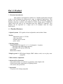
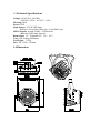
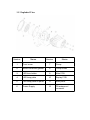
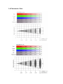
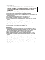
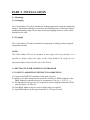
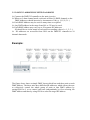
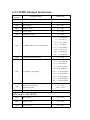
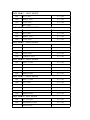
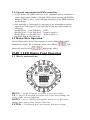
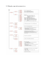
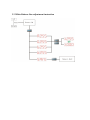
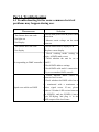
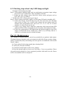
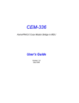
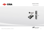
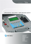
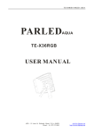
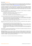
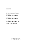
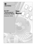
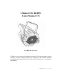
i.Shine 1136 RGBW
Color Stainer CN
USER MANUAL
Thank you very much for choosing our product. For safety purpose, please
read this manual carefully before your operation. This manual included
installation and using information. Please install and operate it according to
this manual.
1136RGBW-V6.0 05.15.2010
Indexing
Part 1 Product (GENERAL)
1.1--PRODUCT INTRODUCTION
1.2--PRODUCT FEATURES
1.3--TECHNICAL SPECIFICATIONS
1.4--DIMENSION
1.5-- EXPLODED VIEW
1.6--PHOTOMETRIC DATA
1.7--SAFETY WARNING
PART 2 INSTALLATION
2.1--MOUNTING
2.2--SETTING UP WITH A DMX512 CONTROLLER
2.2-1--DMX512 ADDRESSING WITHOUT ID ADDRESSING
2.2-2--DMX512 ADDRESSING WITH ID ADDRESS
2.2-3-- DMX Channel instruction
2.2-4—Special instruction of DMX connection
2.3—Master/Salve Operation
PART 3 LED DISPLAY PANEL OPERATION
3.1 -- Basic instruction
3.2 -- Display operation menu tree
3.3 -- White balance adjustment instruction
PART 4 TROUBLESHOOTING
4.1 TROUBLESHOOTING LIST
4.2 Checking steps about why led lamp not light
PART 5 MAINTENANCE
Part 1 Product
1. 1 Product introduction
This product is designed for outdoor use. Suitable applications include
wash or effect lighting for architectural, stage or nightclub applications. This
product can also be installed for use in signage and advertising using the
dynamic functions available with DMX512 control. Direct input of DMX512
signal allows the units to be controlled from any DMX512 controller. This
product can be operated as a single unit or in multiple units for large
applications.
1 . 2 Product Features
* Optical system: 1-256 grades electric adjustable, mini within 100ms
*Strobe:
Adjustable speed , 0-32.5Hz
same step strobe
random electric strobe
pulse strobe
* Working mode:
Standard DMX512 signal (3, 4, 5, 6, 10 channels - 8 modes)
**Intelligent ID addressing separately
**Intelligent ID group addressing
Auto-mode
Master/Salve Mode
* Display panel: 4-LED digital display DMX address code, test or play autoprograms.
* White balance adjustable
* Advanced New Function:
**Set white balance via software to guarantee same bright color
**Self-check inside temperature of lighting fixture.
**Overheat auto-protection.
* Auto-mode:
**8 preset color change programs
1.3 Technical Specifications
Voltage: AC90-259v, 50/60Hz
AC230V--0.25A, AC115V—0.5A
IP rating: IP66
Power: 58W
Light Source: 36*1W LED lamp
Red 9pcs, Green 9pcs, Blue 9pcs, Cool White 9pcs
LED Lifespan: around 30,000 ~ 50,000 hours
(Rated by LED lamp factory)
Beam angle: 15 º(Optional 25º、30 º、45º)
Case: Die-casting aluminum
Net Weight:3.5Kg
Size: 303 x 254 x 165mm
1.4 Dimension
1.5 Exploded View
Number
Name
Number
Name
1
Front cover
7
Clamp
2
Water-resistance gasket
8
Clamp knobs
3
LED lens holder
9
Main PCB
4
LED lamp plate
10
Display PCB
5
LED lamp plate fix panel
11
Rear panel
6
Power Supply
12
PG waterproof
connector
1.6 Photometric Data
1.7 IMPORTANT:
ALWAYS READ THE USER MANUAL BEFORE OPERATION.
PLEASE CONFIRM THAT THE POWER SUPPLY STATED ON THE
PRODUCT IS THE SAME AS THE MAINS POWER SUPPLY IN
YOUR AREA.
☆ This product must be installed by a qualified professional.
☆ Always operate the equipment as described in the user manual.
☆ A minimum distance of 0.5m must be maintained between the equipment and
combustible surface.
☆ The product must always be placed in a well ventilated area.
☆ Always make sure that the equipment is installed securely.
☆ DO NOT stand close to the equipment and stare directly into the LED light
source.
☆ Always disconnect the power supply before attempting and maintenance.
☆ Always make sure that the supporting structure is solid and can support the
combined weight of the products.
☆ The earth wire must always be connected to the ground.
☆ Do not touch the power cables if your hands are wet.
ATTENTION:
☆ This product left the place of manufacture in perfect condition. In order to
maintain this condition and for safe operation, the user must always follow
the instructions and safety warnings described in this user manual.
☆ Avoid shaking or strong impacts to any part of the equipment.
☆ Make sure that al parts of the equipment are kept clean and free of dust.
☆ Always make sure that the power connections are connected correct and
secure.
☆ If there is any malfunction of the equipment, contact your distributor
immediately.
☆ When transferring the product, it is advisable to use the original packaging in
which the product left the factory.
☆ Shields, lenses or ultraviolet screens shall be changed if they have become
damaged to such an extent that their effectiveness is impaired.
☆ The lamp (LED) shall be changed if it has become damaged or thermally
deformed.
PART 2 INSTALLATION
2.1 Mounting:
2.1-1 Hanging
The Color Stainer CN can be mounted in a hanging position using the supporting
bracket. The bracket should be secured to the mounting truss or structure using a
standard mounting clamp. Please note that when hanging the unit a safety cable
should also be used
.
2.1-2 Upright
The Color Stainer CN can be mounted in an upright or sitting position using the
supporting brackets.
NOTE:
The Color Stainer CN can be mounted at any angle and in any position. It is
possible to further adjust the angle of the Color Stainer CN using the two
adjustment knobs located on the side of the fixture.
2.2 SETTING UP WITH A DMX512 CONTROLLER
2.2-1 DMX512 ADDRESSING WITHOUT ID ADDRESSING
☆ Connect the DMX512 controller to the units in series.
☆ When set 10 dmx channel mode, each unit will has 10 DMX channels so the
DMX Addresses should increase by increments of 10 (e.g. 1,11,21,31...)
☆ The ID address has not been set so therefore when using the controller CH10
must be inactive (CH10=0).
☆ Each DMX Address may be used as many times as required.
☆ Any DMX address in the range from 001 to 512 may be used.
2.2-2 DMX512 ADDRESSING WITH ID ADDRESS
☆ Connect the DMX512 controller to the units in series
☆ When set 9 dmx channel mode, each unit will has 10 DMX channels so the
DMX Addresses should increase by increments of 10(e.g. 1,11,21,31...)
☆ Each DMX Address may be used as many times as required.
☆ Any DMX address in the range from 001 to 512 may be used.
☆ Each DMX address may carry up to 50 separate ID addresses.
ID should be set in the menu on each unit in ascending values (i.e. 1, 2, 3...)
☆ ID addresses are accessible from Ch10 on the DMX512 controller at 10
channel dmx mode.
Example:
The figure above shows a simple DMX layout which has used three units at each
DMX address. The three units have different ID addresses which allows the user
to collectively control the whole group of units at that DMX address by
settingCH10 to 0, or to control each unit independently by first selecting the
DMX address and then by using CH10 to select the target ID address。
2.2-3 DMX Channel instruction
Mode /
Channel
Function & Effect
DMX Value
DMX Mode 1- STAG MODE
CH1
Dimmer 0~100%
0<==>255
CH2
RED 0~100%
0<==>255
CH3
GREEN 0~100%
0<==>255
CH4
BLUE 0~100%
0<==>255
CH5
Cool White 0~100%
0<==>255
0<==>5 No function
6<==>40 Red
41<==>76 Green
CH6
COLOR MACRO (7 preset color effect)
77<==>112 Blue
113<==>148 Yellow
149<==>184 Cyan
185<==>220 Purple
221<==>225 White
CH7
Strobe speed from slow to fast
0<==>255
0<==>5 No function
6<==>36 Program 1
37<==>68 Program 2
69<==>100 Program 3
CH8
Auto program - 8 programs
101<==>132 Program 4
133<==>164 Program 5
165<==>196 Program 6
197<==>228 Program 7
229<==>255 Program 8
CH9
CH10
Program Fade in/out time
Program run speed
ID ADDR 0-51 Group
0<==>128
129<==>255
0<==>255
DMX Mode 2- ARC MODE
CH1
RED 0~100%
0<==>255
CH2
GREEN 0~100%
0<==>255
CH3
BLUE 0~100%
0<==>255
DMX Mode 3 - ARC2 MODE
CH1
RED 0~100%
0<==>255
CH2
GREEN 0~100%
0<==>255
CH3
BLUE 0~100%
0<==>255
CH4
White 0-100%
0<==>255
DMX Mode 4 - ARCD MODE
CH1
Dimmer 0~100%
0<==>255
CH2
RED 0~100%
0<==>255
CH3
GREEN 0~100%
0<==>255
CH4
BLUE 0~100%
0<==>255
DMX Mode 5 - AR2D MODE
CH1
Dimmer 0~100%
0<==>255
CH2
RED 0~100%
0<==>255
CH3
GREEN 0~100%
0<==>255
CH4
BLUE 0~100%
0<==>255
CH5
Cool White 0~100%
0<==>255
DMX Mode 6 - ARCS MODE
CH1
Dimmer 0~100%
0<==>255
CH2
RED 0~100%
0<==>255
CH3
GREEN 0~100%
0<==>255
CH4
BLUE 0~100%
0<==>255
CH5
STROBE 0-100%
0<==>255
DMX Mode 7 - AR2S MODE
CH1
Dimmer 0~100%
0<==>255
CH2
RED 0~100%
0<==>255
CH3
GREEN 0~100%
0<==>255
CH4
BLUE 0~100%
0<==>255
CH5
Cool White 0~100%
0<==>255
CH6
STROBE 0-100%
0<==>255
DMX Mode 8 - HSV MODE
CH1
HUE - 256 colors
0<==>255
CH2
SATURATION 0-100%
0<==>255
CH3
VALUE 0-100%
0<==>255
ENTER
UP
ENTER
Yes
UP
DOWN
DOWN
ENTER
E
UP
ENTER
DOWN
2.2-4 Special construction for DMX connection.
E
☆ At last fixture, the DMX cable has to be terminated with UP
a terminator to
reduce signal errors. Solder a 120-ohm 1/4W resistor between
pin 2(DMX-)
DOWN
and pin 3(DMX+) into a 3-pinUPXLR-plug and plug it in the DMX-output of
the last fixture.
DOWN
UP
☆ If the controller is 5-pin output, it’s necessary to use an adaptor to transfer
DOWN
signal from 5-pin output to 3-pin XLR-plug or you can connect cables as
following:
3-pin XLR Pin 1 – 5-pin XLR Pin 1 GND
UP 2 – 5-pin XLR Pin 2
3-pin XLR Pin
Negative signal (-)
3-Pin XLR DOWN
Pin 3 – 5-pin XLR Pin 3 PositiveUP
signal (+)
UP
ENTER
5-pin XLR Pin4 & Pin 5 not used
DOWN
DOWN
2.3 Master/Slave Operation.
ENTER
UP
DOWN
UP
DOWN
The Pro Wash can be linked 15pcs together to work in Master/Salve mode
UP
UPMaster
without any console. The 1st machine will be set as
DOWN
and
DOWN
others will work as Salve
unit at same effect.
PART 3 LED DisplayENTER
Panel UP
Operation
3.1 Basic instruction:
ENTER
DOWN
DOWN
ENTER
ENTER
UP
UP
UP
DOWN
ENTER
UP
DOWN
ENTER
UP
DOWN
ENTER
DOWN
UP
MENU -- menu selection or return to previous menu
UP -- Press UP through the menu list to increase/change the
value of the current function
DOWN -- Press DOWN through the menu list to decrease/
change the value of the current function
ENTER -- Confirm & Quit out current function setting
UP
DOWN
DOWN
3.2 Display operation menu tree
3.3 White Balance fine-adjustment instruction
Part 4, Troubleshooting
4.1 Troubleshooting list for some common electrical
problems may happen during use:
Phenomenon
* The fixture does not work
* No light out
* No Display
Solution
* Check main power fuse & power cable
connection
* Measure main voltage on the main
connector
* The fixture does not work
* Check connection of display PCB
* No display
* Replace a new display
* Check working mode setting on
display is DMX mode or not
* Check whether the unit be set as
No responding to DMX controller SLAVE
* Check DMX address settings
* Check DMX cable and it’s connection
* Try to use another DMX console
* Check whether DMX cables be
connected well or not
* Check whether the DMX cable has to
be terminated with a terminator to
Signal error while use DMX
reduce signal errors. If not, please
Solder a 120-ohm 1/4W resistor between
pin 2(DMX-) and pin 3(DMX+) into a
3-pin XLR-plug and plug it in the
DMX-output of the last fixture
4.2 Checking steps about why LED lamp not light
(Example: Red led lamp not light)
Step 1: Disassemble lighting fixture and use multi-meter to measure input voltage
between R+/ R- on main PCB. There should have DC48V.
** If there no 48V voltage, please check the electro circuit and parts such as
CQ12, R39, R37, Q3 and etc.
** If there have 48V voltage, please go to step 2.
Step 2: Check voltage between R+ and R- on LED lamp PCB and it should be 48V.
** If there has voltage, but LED lamp not work, the reason may be LED lamp
short circuit or burnt. Use a metal cable connect the two points which be
marked with correspondent color such as R+, R-, G+, G-, B+, B- to check
whether it is short circuit one by one
** If there is no voltage, that’s mean the connection cable between lamp PCB
and main PCB is short circuit and just need to replace that connection cable.
** If there has voltage and no LED lamp burnt, the problem might be some LED
lamps on LED PCB not be welded well. Check every led lamp and use a
solder to re-weld those not be welded led lamps.
Part 5, Maintenance
The cleaning of internal must be carried out periodically to optimize light output.
Cleaning frequency depends on the environment in which the fixture operates: damp,
smoky or particularly dirty surrounding can cause greater accumulation of dirt on the
fixture’s optics.
☆ Clean with soft cloth using normal glass cleaning fluid.
☆ Always dry the parts carefully.
☆ Clean the external optics at least every 20 days.
☆Clean the internal optics at least every 30/60 days – Up to vary products. Please
ask professional technical to clean waterproof products and make sure the fixture
will be reassembled well for waterproof
- 16 -