1
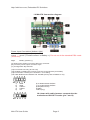
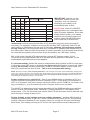
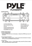
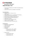
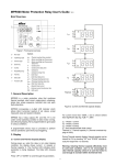
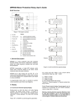
M4-ATX
6-30V Intelligent ATX Power Supply
Installation Guide
Version 1.0e
P/N M4-ATX-01
Before you start…
Please take a moment and read this manual before you install the M4-ATX in your
vehicle. Often times, rushing into installing the unit can result in serious damage
to your M4-ATX board, computer and probably your car’s electrical system. Always
double check the polarity of your wires with a voltmeter.
Avoid using the cigarette plug as a power source, often times the contacts are not
capable of delivering high current to your PC.
Introduction
Thank you for purchasing the M4-ATX power sequencer / vehicle ATX power supply.
The M4-ATX was designed to work with a wide variety of main boards ranging from low
power to fully fledged Intel, AMD or VIA motherboards.
M4-ATX Logic Diagram
+
Battery
GND
PC
+
Reverse and
forward protection
Switch Logic
-
6-30V DC-DC
ATX PSU
ATX power
Mother Board
ON/OFF switch
Ignition SW
8bit MCU
Amplifier
Enable
M4-ATX
Status LED
USB
http://mini-box.com, Embedded PC Solutions
1.2 M4-ATX Connection diagram
Power Input Connectors (bottom, right)
Left
Center
Battery negative (GND)
Ignition (To start connect to Battery +). Do not use in the standard PSU mode
(mode P0)
Right
Battery positive (+)
(A) ATX Power Output Connector 20/24 pin connector
(B) 12V-ATX power output connector 4 pin
(C) Configuration dip switches
(J5) For internal use only (do not use)
(J6) Amplifier THUMP wire harness (connects to the M4-ATX pin header)
(J3) Fan Header. Positive pin is closest to “J3” marking.
(J8) USB, Motherboard ON/OFF and THUMP (Thump also available on J6)
1)
2)
3)
4)
5)
GND
GND
USB D+
USB DVcc
6) To Motherboard ON/OFF
7) To motherboard ON/OFF
8) Amplifier Thump
9) GND
19 N/C (key)
J8 shown with cable harness connected to the
motherboard ON-OFF header (pin 7 and 6)
M4-ATX User Guide
Page 2
http://mini-box.com, Embedded PC Solutions
DIP Switch (ON=down)
1
2
3
P
Off-delay
Hard-off
(All rails ON) (5VSB)
OFF OFF OFF
P0
Standard PSU mode
ON
P1
OFF OFF
5sec + 1min AutoLatch*
1 min
OFF ON
OFF
P2
1min + 1min AutoLatch*
NEVER
ON
OFF
ON
P3
1min + 1min AutoLatch*
1min
OFF OFF ON
P4
15min
1min
ON
NEVER
OFF ON
P5
15min
OFF ON
ON
P6
30min
1min
ON
ON
P7
2hour
NEVER
ON
IMPORTANT: Always use the
“Hibernate” feature, never use
“Standby” as it can severely
discharge your battery over
extended periods of time.
NEVER use “hard-off = NEVER”
settings unless you understand the
risks of battery depletion. Even with
safety limits in place, your battery
might be not be able to start your
engine. “Hard-off=NEVER keeps
your 5VSB rail on at all times”
*AutoLatch is active during the fist 60s of PC operation (and only during the first 60
seconds). For example, If Ignition is turned ON and then OFF right away, M4-ATX will
latch Ignition in ON position for the next 60 seconds, allowing your operating system
to fully come up. This will prevent disk drive corruption or systems that remain hung in
the ON position. After the first 60 seconds of system operation, the AutoLatch feature will
be removed and system will shut down at as governed by the “Off-delay” setting.
P0: In this mode, the M4-ATX behaves like a regular ATX power supply. If J6 is
connected to the motherboard, M4-ATX will also send a gratuitous “ON pulse” to the
motherboard right after power is first applied.
P1 (recommended): Sends ON pulse to motherboard when ignition is ON for more than
5 seconds, sends OFF pulse to motherboard 5 seconds after ignition is turned off. Waits
another 60 seconds and then shuts down 5VSB to conserve battery. In this mode, the
M4-ATX consumes less than 0.5mA. This is our recommended setting.
NOTE: Should you need to reset to factory defaults (in case changes were made via the USB uplink), simply power
off the unit, connect a jumper to JP1 and then apply power back up for more than 2 seconds. The LED light will start to
flash rapidly indicating that the factory defaults were loaded. Don’t forget to Remove jumper! Disconnect M4-ATX
from battery for at least few seconds. You are done!
Power challenges in a vehicle PC: One of most difficult tasks of operating a PC in a
vehicle is power consumption while the computer is OFF. Even when your computer is
OFF or in Suspend, it will still consume about 50-150mA on the 5VSB rail. No matter how
big your battery is, you will eventually drain it if proper actions are not taken.
The M4-ATX is addressing these issues by cutting off the 5VSB rail after a pre-defined
amount of time (see jumper chart, HARDOFF). During HARDOFF if the battery level
drops below 11.2V for more than one minute, M4-ATX will shut down and re-activate only
when the input voltage is above 12V.
Engine Cranks, under-voltage and over-voltage situations. Another difficult task is
maintaining stable power to your PC. While car batteries are rated at 12V, they actually
provide voltages in between 8-16V (engine cranks) or as high as 80 volts (load dump).
Most times, your battery will stay at 13.5V but extra precautions need to take place in
M4-ATX User Guide
Page 3
http://mini-box.com, Embedded PC Solutions
order to prevent such situations. M4-ATX operates as low as 6V and as high as 30V
while providing strict regulation as well as input voltage clamping and reverse protection.
Anti-Thump: If your PC is connected to your car amplifier, you will hear a loud pop when
the computer is first started. The M4-ATX has an ‘anti-thump’ control that will keep your
amp OFF while the PC starts. Simply connect the 2 pin wire to J6 harness to your
amplifier remote control pins. The pin at the edge of the PCB is GND, inner pin is HOT.
Mode of operation explained
1)
Ignition=OFF. Nothing happens. M4-ATX is waiting for ignition signals.
2)
Ignition=ON. M4-ATX waits for few seconds then turns on the 5VSB rail. After another second M4-ATX
sends an “ON” signal to the motherboard via the 2 wires connected to the motherboard’s ON/OFF pins.
The motherboard will turn ON and your system should start booting. The Ignition state will be latched for
60 more seconds so that the motherboard will have a change to come up in a clean manner.
3)
Ignition=ON. Your computer will remain ON.
4)
Ignition=OFF. M4-ATX waits for “OFFDELAY” in seconds (see jumper chart) and then it turns the
motherboard OFF by sending a signal to the motherboard’s ON/OFF switch. Your computer should turn
off gracefully (shutdown procedure). After shutdown, 5VSB will still be provided for another “HARDOFF”
seconds. In the event where the shutdown process is longer than “HARDOFF” (Operating System gets
frozen, etc), power will be shut down hard, turning off all power rails. During the HARDOFF procedure,
the battery levels will be constantly monitored to prevent deep discharge situations.
5)
M4-ATX will go to step 1, if ignition is tuned ON again.
NOTE. When all dip switches are off, M4-ATX acts as a regular power supply. M4-ATX will also send a gratuitous “ON”
pulse (to the ON/OFF motherboard pins, should you have a wire harness connected to it) when power is applied for the
first time. Do not connect the on/off switch if you don’t want your PC to be started automatically.
M4-ATX Characteristics
Minimum Input Operating. voltage
6V
Maximum input Operating voltage
30V (hard clamping will occur at 34V)
Deep-Discharge shutdown threshold
11.2V
Input current limit (fuse protected)
Mini-blade 25A
Max Output Power
250 Watts / 300 watts peak
Deep Sleep Current Consumption.
< 1.6mA
Storage and operating temperature
-40 to +125 degrees Celsius (storage), -40 – 65C (operating)
MTBF
200,000 Hrs
Efficiency (Input 10-16V)
>95%, all rails combined, 50% load.
Input connectors
M4 screw terminal
Output Connector
ATX Power 24 pin (Molex P/N 39-01-2200)
*Unit shuts down when internal temperature sensor indicates > 85C. This value can be changed with software.
Maximum Power Characteristics
Output Rail
Current (Max)
Current Peak
Regulation
(<30 seconds)
5V
15A
20A
1.5%
3.3V
15A
20A
1.5%
5VSB
1.5A
2A
1.5%
-12V
0.15A
0.2A
10%
12V
12A (see below)
16A (see below)
2%
When operating at <8V or >28V or extreme temperatures, de-rate by 25-50%, ventilation might be required.
When operating at constant 160watts or more forced ventilation might be required.
12V Rail Output Current (12V buck/boost converter)
Input (V)
12V out current
Input (V)
6-8V
8A
11-16V
8-11V
10A (12A peak)
16-30V
12V out current
12A (16A peak)
12A (14A peak)
Support and warranty: Standard Hardware Warranty 1Year / US, 2 Year EU.
M4-ATX User Guide
Page 4