1
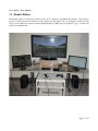
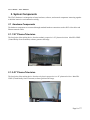
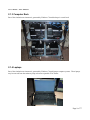
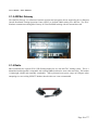
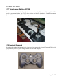
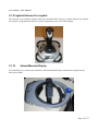
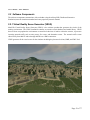
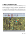
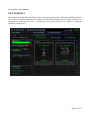
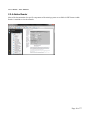
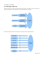
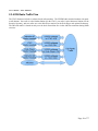
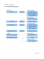
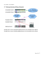
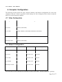
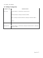
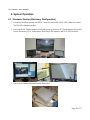
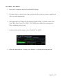
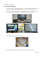
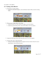
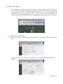
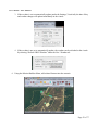
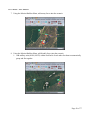
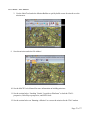
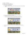
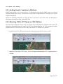
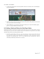
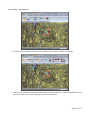
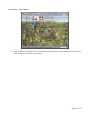
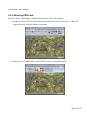
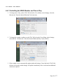
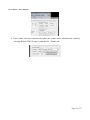
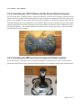
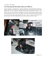
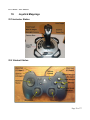
User's Manual – JTAC Simulator JTAC Simulator User's Manual Copyright (c) 2012 Battlespace Simulations, Inc. All rights reserved. Printed in the United States. Battlespace Simulations, Modern Air Combat Environment, and the MACE and BSI logo are trademarks of Battlespace Simulations, Inc. MetaVR, Virtual Reality Scene Generator, VRSG, Metadesic, the phrase "geospecific simulation with game quality graphics", and the MetaVR logo are trademarks of MetaVR, Inc. Metadesic is protected by US Patent 7,425,952. All other trademarks are owned by their respective companies. Battlespace Simulations, Inc. 111 W. San Antonio St. Ste 210-5 New Braunfels, TX 78130 Phone: 210-857-9672 www.bssim.com [email protected] MetaVR, Inc. 80 Somerset Rd. Brookline, MA 02445 Phone: 617-739-2667 www.metavr.com [email protected] Page 1 of 77 User's Manual – JTAC Simulator Contents 1. 2. Training System Purpose and Use 1.1 Instructor Station 5 1.2 Role-Player Station 6 1.3 Student Station 7 System Components 2.1 Hardware Components 8 8 2.1.1 50” Plasma Television 8 2.1.2 42” Plasma Television 8 2.1.3 Computer Rack 9 2.1.4 Laptops 9 2.1.5 ARCNet Gateway 10 2.1.6 Radio 10 2.1.7 Thrustmaster Warthog HOTAS 11 2.1.8 Logitech Gamepad 11 2.1.9 Logitech Extreme Pro Joystick 12 2.1.10 Helmet Mounted Display 2.2 Software Components 12 13 2.2.1 Virtual Reality Scene Generator (VRSG) 13 2.2.2 Modern Air Combat Environment (MACE) 14 2.2.3 T.A.R.G.E.T 15 2.2.4 Adobe Reader 16 2.3 3. 5 Network Components 17 2.3.1 Distributed Interactive Simulation (DIS) 17 2.3.2 ARCNet Gateway 17 2.3.3 DIS Entity Traffic Flow 18 2.3.4 DIS Radio Traffic Flow 19 Facility Installation 20 3.1 Room Requirements 20 3.2 Power Requirements 20 Page 2 of 77 User's Manual – JTAC Simulator 4. 3.3 Display Wiring Schematic 20 3.4 Control Wiring Schematic 21 3.5 Audio Wiring Schematic 22 3.6 Network Wiring Schematic 23 3.7 Gateway Hardware Wiring Schematic 24 Computer Configuration 4.1 Video Configuration 25 4.2 Network Configuration 25 4.3 Database Configuration 27 4.3.2 4.4 5. 6. 25 IOS Database 27 Software Configuration 29 4.4.1 JTAC IOS 30 4.4.2 Role-Player IOS 32 4.4.3 JTAC Visual 34 4.4.4 HMD Visual 37 4.4.5 FMV Visual 40 4.4.6 Role-Player Visual 43 System Maintenance 46 5.1 Upgrading VRSG Software 46 5.2 Upgrading MACE Software 46 5.3 Updating Visual Database Entity Mappings (Unclassified) 47 5.4 Updating Visual Database (Terrain) 47 5.5 Updating IOS Map Database 48 5.6 Updating IOS Imagery Database 49 System Operation 50 6.1 Simulator Startup (Stationary Configuration) 50 6.2 Simulator Shutdown 52 6.3 Creating a New Mission 53 6.4 Opening an Existing Mission 58 6.5 Latching Visuals / Joysticks to Platforms 60 Page 3 of 77 User's Manual – JTAC Simulator 6.5.1 Attaching JTAC's 50” Plasma to JTAC Platform 60 6.5.2 Adding / Attaching Platforms for Role-Player Station 61 6.5.3 Attaching FMV Feed 64 6.6 Running a Mission 65 6.6.1 Controlling the VRSG Weather and Time of Day 66 6.6.2 Controlling the JTAC Platform with the Student Station Gamepad 68 6.6.3 Controlling the FMV feed from the Instructor Station Joystick 68 6.6.4 Controlling the Role-Player Platform and FMV feed 69 6.6.5 How to Use the Radio 70 6.6.6 How to Use the HMD 70 6.6.7 MACE / IOS Operation 70 7. Troubleshooting 71 8. License Information 74 8.1 VRSG License Keys 74 8.2 MACE License Keys 74 9. Acronyms 10. Joystick Mappings 75 76 10.1 Instructor Station 76 10.2 Student Station 76 10.3 Role-Player Station 77 Page 4 of 77 User's Manual – JTAC Simulator 1. Training System Purpose and Use The JTAC Simulator provides both day and night, Call for Fire and Close Air Support Type 1, 2, and 3 training to JTAC (Joint Terminal Attack Controller) students. The system contains Unclassified visual and model databases for stand-alone training, but it can also be connected with sites around the world for Classified Distributed Mission Operations (DMO) training. The system is composed of three primary stations: Instructor, Role-Player, and Student. 1.1 Instructor Station The Instructor Station is the primary scenario generation and control station. It includes a console to control the JTAC IOS, the UAV camera, a joystick to control the UAV (Unmanned Aerial Vehicle) camera, and a radio for communication. The instructor loads the appropriate scenario and attaches the JTAC Visual to one of the entities within the scenario from this station. An instructor may optionally control a UAV camera that outputs to the student's FMV (Full Motion Video). Page 5 of 77 User's Manual – JTAC Simulator 1.2 Role-Player Station The Role-Player Station is used by instructors to obtain complete control of a selected entity within the scenario. Common uses would be to have a pilot fly an air asset such as an A-10 in the scenario, act as a second JTAC student within the scenario, or act as an opposing force. The Role-Player enables greater control and flexibility for the instructor over constructive forces at the expense of higher instructor workload. The Role-Player contains a plasma television for out the window view, a single monitor for instruments and situational awareness, a Warthog HOTAS (Hands On Throttle and Stick) for flight controls, and a radio for communication. Page 6 of 77 User's Manual – JTAC Simulator 1.3 Student Station The Student Station is the primary position for the JTAC students to coordinate their attacks. Their primary visual is a plasma television, but they also have displays for their FMV feeds. A gamepad is available for the JTAC to move within the scenario, a Helmet Mounted Display (HMD) for viewing during Type 1 Controls, and a radio for communication. Page 7 of 77 User's Manual – JTAC Simulator 2. System Components The JTAC Simulator is an integration of many hardware, software, and network components interacting together to build an immersive environment for training. 2.1 Hardware Components The hardware components are connected through standard hardware connections such as DVI video cables and Ethernet network cables. 2.1.1 50” Plasma Television The focal point of the training device from the student's perspective is 50” plasma television. MetaVR's VRSG (Virtual Reality Scene Generator) software generates the image. 2.1.2 42” Plasma Television The focal point of the training device from the role-player's perspective is a 42” plasma television. MetaVR's VRSG (Virtual Reality Scene Generator) software generates the image. Page 8 of 77 User's Manual – JTAC Simulator 2.1.3 Computer Rack Part of the simulation environment is generated by Windows 7 based desktops in a small rack. 2.1.4 Laptops Part of the simulation environment is generated by Windows 7 based laptops computer systems. These laptops may be removed from the stationary setup to become a portable JTAC trainer. Page 9 of 77 User's Manual – JTAC Simulator 2.1.5 ARCNet Gateway The ARCNet Gateway is a collection of network switches and encryption devices supplied by the Air National Guard's Distributed Training Operations Center (DTOC) to facilitate DMO training over ARCNet. The JTAC Simulator communicates through the Gateway for Classified DMO training with sites around the world. 2.1.6 Radio BSI recommends the Logitech G330 USB Gaming headset for use with the JTAC training system. This is a behind-the-head design that is compatible with existing HMDs (both can be worn at the same time). The headset is lightweight, reliable and reasonably comfortable. BSI experienced some power surges on USB ports when attempting to re-use existing USB PTT headset, therefore their use is not recommended. Page 10 of 77 User's Manual – JTAC Simulator 2.1.7 Thrustmaster Warthog HOTAS The instructor or student at the Role-Player Station controls entities with a Thrustmaster Warthog HOTAS. The joystick is programmed with its T.A.R.G.E.T driver software and MACE's (Modern Air Combat Environment) joystick configuration on the Role-Player IOS computer. 2.1.8 Logitech Gamepad The student at the Student Station controls his viewpoint and movement with a Logitech Gamepad. The joystick is programmed by MACE's joystick configuration on the JTAC IOS computer. Page 11 of 77 User's Manual – JTAC Simulator 2.1.9 Logitech Extreme Pro Joystick The instructor at the Instructor Station controls the simulated FMV feed by a Logitech Extreme Pro Joystick. The joystick is programmed by MACE's joystick configuration on the JTAC IOS computer. 2.1.10 Helmet Mounted Display For controlling Type 1 controls, the student uses a Helmet Mounted Display attached to the laptop from the Role-Player station. Page 12 of 77 User's Manual – JTAC Simulator 2.2 Software Components The software components communicate with each other using the military DIS (Distributed Interactive Simulation) network simulation standard and some proprietary network formats. 2.2.1 Virtual Reality Scene Generator (VRSG) MetaVR's Virtual Reality Scene Generator (VRSG) is the software product that generates the visuals of the training environment. The VRSG installation contains an extensive terrain database and model library. VRSG however does not populate the environment or control the behaviors of entities within the scenario, it processes incoming network traffic such as entity states, fire events, and detonation events. The network traffic comes either locally from MACE and/or through ARCNet as a DMO connection. VRSG generates all the visual scenes for the simulator including the plasma televisions, HMD, and FMV feed. Page 13 of 77 User's Manual – JTAC Simulator 2.2.2 Modern Air Combat Environment (MACE) MACE provides the computer generated forces (CGF), sometimes called semi-autonomous forces (SAF), as well as scenario creation, management, and instructor operator station (IOS) features. It simulates physics-based tactics and behaviors of the entities in the simulation. When training in a stand-alone environment, all entities of the simulation are produced by MACE; when training in a DMO environment, MACE provides the JTAC entity and other entities as appropriate. MACE's interface displays entities in the environment overlaid onto Compressed Arc Digitized Raster Graphic (CADRG) formatted charts and high-resolution terrain imagery. MACE itself performs no scenery generation but instead broadcasts the scenario information over the military DIS network protocol to the VRSG visual channels. MACE acts as the primary IOS at the Instructor Station and a secondary role-player IOS at the Role-Player Station. Page 14 of 77 User's Manual – JTAC Simulator 2.2.3 T.A.R.G.E.T The instructor or student at the Role-Player station controls the platforms with a Thrustmaster Warthog HOTAS. The T.A.R.G.E.T software combines the two separate stick and throttle components into a single joystick device and adjusts the sensitivity of the axes. A configuration file is selected and run in T.A.R.G.E.T. during the simulator's startup process. Page 15 of 77 User's Manual – JTAC Simulator 2.2.4 Adobe Reader Most of the documentation for specific components of the training system are available in PDF format. Adobe Reader is installed to view the manuals. Page 16 of 77 User's Manual – JTAC Simulator 2.3 Network Components The JTAC Simulator communicates its simulation information via a military networking standard known as Distributed Interactive Simulation (DIS). For Distributed Mission Operation (DMO) communication, the simulator may be connected to the ARCNet gateway. The gateway facilitates DIS traffic between the local installation and sites throughout the world. 2.3.1 Distributed Interactive Simulation (DIS) Distributed Interactive Simulation is the IEEE 1278 standard commonly used for networked simulation in the Department of Defense. The standard is a description of uni-directional packets (UDP) which allows different simulation software to communicate with one another. It has no central server for other simulations to connect to. Rather, each simulation maintains its own entities and broadcasts them out for other simulations to interactive with. In addition to the network packet format, the Simulation Interoperability Standards Organization (SISO) tabulates enumerations for real-world entities that are referenced in the simulated environment. These common enumerations are used to ensure a F-16 aircraft on one simulator is referenced as a F-16 aircraft on another. The training system conforms to DIS standard IEEE 1278.1-1995/1998 protocols and the SISO reference 010-2011 for enumerations. 2.3.2 ARCNet Gateway As the JTAC Simulator conforms to the DIS networking standard, it may connect to other simulators locally or throughout the world for distributed training. Distributed Training Operations Center (DTOC) is the Air National Guard's central agency for connecting Air Guard simulators and running them in a single scenario. To connect to the DTOC, the simulator communicates through a Classified connection known as ARCNet 1. The training dome must be configured for Classified operations prior to connecting to ARCNet. Communication is made through the ARCNet Gateway system of components supplied by the DTOC. Page 17 of 77 User's Manual – JTAC Simulator 2.3.3 DIS Entity Traffic Flow DIS entities include all air platforms, ground platforms, and weapons in the simulation. There are three sources that generate DIS entities in the simulation: JTAC IOS, Role-Player IOS, and ARCNet. Many of the computer systems of the simulator receive and process the incoming DIS entities. Page 18 of 77 User's Manual – JTAC Simulator 2.3.4 DIS Radio Traffic Flow The JTAC Simulator includes a software based radio emulator. The VIPERS radio includes headsets with pushto-talk buttons. One radio is at the Student Station (for the JTAC), one radio is at the Instructor Station (for the Scenario Operator), and two radios are at the Role-Player station (for the Role-Player and optional Instructor). The DIS radio traffic is shared not only over the local network but also via the ARCNet connection during DMO exercises. Page 19 of 77 User's Manual – JTAC Simulator 3. Facility Installation The JTAC Simulator requires substantial physical space, electrical capacity, and security safeguards to take full advantage of its training capabilities. 3.1 Room Requirements For optimal training, the room should be at least 15'x15' to sufficiently space the different stations. Although the exact arrangement of the stations and computer systems have some flexibility, the Role-Player station should have visibility of the Student station and the Instructor station should have visibility of the Role-Player and Student stations. 3.2 Power Requirements 1x 120V 15 Amp Server Rack 1x 120V 15 Amp Student Station 1x 120V 15 Amp Instructor Station 1x 120V 15 Amp Role-Player Station 3.3 Display Wiring Schematic Page 20 of 77 User's Manual – JTAC Simulator 3.4 Control Wiring Schematic Page 21 of 77 User's Manual – JTAC Simulator 3.5 Audio Wiring Schematic Page 22 of 77 User's Manual – JTAC Simulator 3.6 Network Wiring Schematic Page 23 of 77 User's Manual – JTAC Simulator 3.7 Gateway Hardware Wiring Schematic Warning: Do not connect Unclassified equipment directly to the Classified Switch or Router. Warning: Do not connect Classified equipment directly to the Unclassified Switch or Router. Page 24 of 77 User's Manual – JTAC Simulator 4. Computer Configuration The following sections include the Video, Network, Database, and Software configurations for each of the computers in the rack. If there is a problem in which settings were lost or changed, use these values to return the dome to its original operating condition. 4.1 Video Configuration Computer Name Video Image JTAC Visual 50” Plasma (1920x1080) JTAC IOS Monitor (1920x1080) JTAC FMV Cloned: Monitor (1920x1080) & Monitor (1920x1080) JTAC HMD Cloned: Monitor (1280x1024) & HMD (1280x1024) Role-Player Visual 42” Plasma (1920x1080) Role-Player IOS Monitor (1920x1080) 4.2 Network Configuration Computer Name Network Name DIS IP DIS Site/App/Entity JTAC Visual 192.168.1.100 10/10/10 JTAC IOS 192.168.1.101 1/101/### JTAC FMV 192.168.1.104 30/30/30 JTAC HMD 192.168.1.105 40/40/40 Role-Player Visual 192.168.1.102 20/20/20 Role-Player IOS 193.168.1.103 1/103/### Port 3000 must be allowed through any configured firewalls for DIS traffic. External connections / gateways Page 25 of 77 User's Manual – JTAC Simulator should only allow port 3000 DIS and IP Phone traffic to pass. Page 26 of 77 User's Manual – JTAC Simulator 4.3 Database Configuration Entity Mappings The Animations, Effects, Models, and Sounds folders contain configuration for how entities and events are displayed and heard in VRSG. The Unclassified version of those configuration files are supplied by MACE. The Classified version of those configuration files are supplied by DTOC to ensure consistent visual representation across a large DMO training environment. The mappings are copied locally on each computer running VRSG: C:\Program Files (x86)\MetaVR\VRSG 5\Animation C:\Program Files (x86)\MetaVR\VRSG 5\Effects C:\Program Files (x86)\MetaVR\VRSG 5\Models C:\Program Files (x86)\MetaVR\VRSG 5\Sounds Overlays The Overlays folder contains VRSG overlay files supplied by MACE for drawing Heads Up Displays (HUD) over the visual image. The HUD is used in the Role-Player's out the window visual. The mappings are copied locally on each computer running VRSG: C:\Program Files (x86)\MetaVR\VRSG 5\Overlays Terrain The Terrain folder contains terrain files (MDS) read by both VRSG and MACE. VRSG reads both the ground imagery and elevation information from the terrain files. MACE reads only the elevation information from the terrain files to ensure correlations between its knowledge of the ground with the visual system. The terrain data files are located on each of the desktop computer systems on their D drive. The laptops contain the terrain files in the root of their C drive. Scenery / Background Cultural The Cultural folders contains metadesic cultural files (CLT). CLT files are mappings of static scenery such as trees, background (indestructible) buildings, and background (indestructible) vehicles. The cultural mappings provide a more visually immersive environment without the additional network overhead from DIS entity state packets. Their downside is that the models displayed are not targetable or destructible. The scenery / background cultural files are located alongside their MDS terrain files. 4.3.2 IOS Database MACE uses elevation, map, and imagery databases to help the operator build and manage scenarios. Although it is possible to load map and imagery data from Classified sources, all IOS data on the simulator is and should remain Unclassified. Those data files are stored on both the JTAC IOS, Role-Player IOS, and FMV IOS computers: Page 27 of 77 User's Manual – JTAC Simulator C:\Elevation_Data C:\MACE_Maps C:\MACE_Imagery MACE reads raw DTED files as a base elevation data source. Although the elevation data in DTED will be similar to the MDS terrain tiles, they will vary slightly. If MDS terrain tiles are available, MACE will read those before its DTED files to ensure proper correlation with the visuals (the mountain peak on the map matches the mountain peak in the visual). MACE reads CADRG files to display GNC, JNC, JOG, TPC, and other map scales on the operator's map. As the operator zooms in and out, MACE will automatically use the available map scale. For better scenario development and control, MACE can also read TIFF imagery files that match the imagery embedded in the MDS terrain tiles. MACE will automatically switch to imagery when the operators zooms in very closely to an area. The TIFF imagery files were built form the same source as the MDS terrain to ensure proper correlation (a road on the map matches the road in the visual). Page 28 of 77 User's Manual – JTAC Simulator 4.4 Software Configuration Computer Name Installed Software JTAC Visual Microsoft Windows 7, Adobe Reader X, MetaVR VRSG 5 JTAC IOS Microsoft Windows 7, Adobe Reader X, Battlespace Simulations MACE 1, Battlespace Simulations DIScord 1, Battlespace Simulations VIPER 1 JTAC FMV Microsoft Windows 7, Adobe Reader X, MetaVR VRSG 5, Battlespace Simulations MACE 1, Battlespace Simulations DIScord 1, Battlespace Simulations VIPER 1 JTAC HMD Microsoft Windows 7, Adobe Reader X, MetaVR VRSG 5, Battlespace Simulations VIPER 1 Role-Player Visual Microsoft Windows 7, Adobe Reader X, MetaVR VRSG 5 Role-Player IOS Microsoft Windows 7, Adobe Reader X, Battlespace Simulations MACE 1, Battlespace Simulations VIPER 1 Page 29 of 77 User's Manual – JTAC Simulator 4.4.1 JTAC IOS The primary simulation software running on the JTAC IOS is MACE. The computer is configured for the following key capabilities: Loading / playing the scenario. Attach the JTAC Visual viewpoint onto an entity in the scenario. Gamepad for the student to control the entity the dome is attached to. Joystick for the instructor to control the UAV camera. Control the weather of the JTAC Visual, Role-Player Visual, JTAC FMV Visual, and JTAC HMD Visual. Startup Batch File @echo off echo Starting simulator... C:\Simulator\Sleep.exe 30000 start /d "C:\Program Files (x86)\Battlespace Simulations\Viper DIS Radio\" DISRadio.exe start /d "C:\Program Files (x86)\Battlespace Simulations\MACE\" MACE.exe MACE Configuration View Settings as desired. Logging Settings as desired. Mission Settings as desired. Nav / Weather Settings as desired. Data Paths CADRG Map Data: C:\MACE_Maps Hi-Res Imagery Map Data: C:\MACE_Imagery Elevation Data: C:\Elevation_Data, D:\MDS_Terrain Elevation Types: VRSG-MDS, DTED, SRTM, VRSG-MDX Communication IP Address of this MACE Instance: 192.168.1.101 All other settings: Not Applicable Page 30 of 77 User's Manual – JTAC Simulator DISNet DIS Broadcast IP: 192.168.1.255 Port: 3000 MACE Identification on Network: Site: 1 Application: Set Broadcasted Site Azimuth to Target Direction: Disabled DR Algorithm: 4 DIS Version: 5 - 1278.1-1995 or 6 - 1278.1-1998 DIS Ownship / External Aircraft to Autolatch: Disabled Use Defaults for Unknown Incoming Entities: Enabled Auto Enabled DIS for All Platforms: Enabled Send: All Enabled Receive: All Enabled 101 Exercise: 13 MACENet Role of this MACE Instance: 0-Stand-Alone IP Address of MACENet Broadcast: Not Applicable MACENet Filter: All Disabled Visual Platform Burn Time (min): 10 Platform Smoke Time (min): 30 Site Burn Time (min): 20 Site Smoke Time (min): -1 Broadcast IR Signatures: Enabled VRSG Visual (Ownship / Man-In-The-Loop) Site: 10 Application: 10 Entity: 10 Auto Attach to Latched Entity: Enabled Set FOV / HUD Enabled: Enabled Window Width: 1920 Height: 1080 VRSG Visual (Ownship Equipment) Site: 40 Application: 40 Entity: 40 Auto Attach to Latched Entity: Enabled VRSG Visual (Weather) Auto Update: Enabled (If Desired), Disabled (During DMO) Site: 0 Application: 0 Entity: 0 VRSG Visual (Camera) Enabled: Enabled Site: 30 Application: 30 Entity: 30 Slew Rate: 0.01 Joystick Map buttons per joystick mapping diagrams. Take Joystick Control with Axis Movement: Enabled Page 31 of 77 User's Manual – JTAC Simulator 4.4.2 Role-Player IOS The primary simulation software running on the Role-Player IOS is MACE. The computer is configured for the following key capabilities: Adding virtual aircraft into the scenario to fly by a pilot. Attach the Role-Player Visual's viewpoint onto the virtual aircraft entity in the scenario. HOTAS for the instructor to pilot the virtual aricraft. HOTAS for the instructor to control the targeting pod camera. Startup Batch File @echo off echo Starting simulator... C:\Simulator\Sleep.exe 30000 start /d "C:\Program Files (x86)\Battlespace Simulations\Viper DIS Radio\" DISRadio.exe start /d "C:\Program Files (x86)\Thrustmaster\TARGET\x64\" TARGETGUI.exe MACE Configuration View Settings as desired. Logging Settings as desired. Mission Settings as desired. Nav / Weather Settings as desired. Data Paths CADRG Map Data: C:\MACE_Maps Hi-Res Imagery Map Data: C:\MACE_Imagery Elevation Data: C:\Elevation_Data, D:\MDS_Terrain Elevation Types: VRSG-MDS, DTED, SRTM, VRSG-MDX Communication IP Address of this MACE Instance: 192.168.1.103 All other settings: Not Applicable DISNet DIS Broadcast IP: 192.168.1.255 Port: 3000 MACE Identification on Network: Site: 1 Application: Set Broadcasted Site Azimuth to Target Direction: Disabled DR Algorithm: 4 103 Exercise: 13 Page 32 of 77 User's Manual – JTAC Simulator DIS Version: 5 - 1278.1-1995 or 6 - 1278.1-1998 DIS Ownship / External Aircraft to Autolatch: Disabled Use Defaults for Unknown Incoming Entities: Enabled Auto Enabled DIS for All Platforms: Enabled Send: All Enabled Receive: All Enabled MACENet Role of this MACE Instance: 0-Stand-Alone IP Address of MACENet Broadcast: Not Applicable MACENet Filter: All Disabled Visual Platform Burn Time (min): 10 Platform Smoke Time (min): 30 Site Burn Time (min): 20 Site Smoke Time (min): -1 Broadcast IR Signatures: Enabled VRSG Visual (Ownship / Man-In-The-Loop) Site: 20 Application: 20 Entity: 20 Auto Attach to Latched Entity: Enabled Set FOV / HUD Enabled: Enabled Window Width: 1920 Height: 1080 VRSG Visual (Ownship Equipment) Site: 1 Application: 1 Entity: 1 Auto Attach to Latched Entity: Disabled VRSG Visual (Weather) Auto Update: Enabled (If Desired), Disabled (During DMO) Site: 0 Application: 0 Entity: 0 VRSG Visual (Camera) Enabled: Disabled Site: 30 Application: 30 Entity: 30 Slew Rate: 0.01 Joystick Map buttons per joystick mapping diagrams. Take Joystick Control with Axis Movement: Enabled T.A.R.G.E.T Configuration Add Game Association Title: MACE Path: "C:\Program Files\Battlespace Simulations\MACE\MACE.exe" Associate Configuration: C:\Program Files\Battlespace Simulations\MACE\xml\MACE.fcf Page 33 of 77 User's Manual – JTAC Simulator 4.4.3 JTAC Visual The primary simulation software running on the JTAC Visual is VRSG Metadesic. The computer is configured for the following key capabilities: Displaying scenario entities. Attached to the JTAC entity by JTAC IOS. Playing scenario audio. Startup Batch File @echo off echo Starting simulator... C:\Simulator\Sleep.exe 30000 start /d "C:\Program Files (x86)\MetaVR\VRSG 5\Bin\" VrsgMds.exe -ignoreJoystick -autostart VRSG Metadesic Configuration Startup Parameters UDP Port: 3000 Exercise ID: 0 Enable Sensor Modes: Enabled Enable RADAR: Disabled Enable Mission Functions: Disabled Enable 3D Sound: Enabled Advanced... DIS Version: 6 Destination Address: 192.168.1.255 Use High Order DRA: Enabled Entity Timeout Period: 7 DIS Presence: None Site: 10 Host: 10 Entity: 10 UAV Ports and Address: Not Applicable Alternate Directories for Terrain, Models, and Textures: D:\MDS_Terrain Attach Options Attach Mode: Mimic Advanced Mimic Mode Offset X: 0.0 Mimic Mode Offset Y: 0.0 Page 34 of 77 User's Manual – JTAC Simulator Mimic Mode Offset Z: -2.5 Lock Position: Disabled Joystick Slewable: Enabled Display Vehicle: Disabled Gunner View Offset: Not Applicable UAV Options: Not Applicable Remote Stealth: Slave Attach to munitions fires from the vehicle I'm attach to: Disabled Viewpoints Not Applicable Graphics Field-Of-View (Degrees): 60 Near Clip (Meters): 0.1 Far Clip (Meters): 100000 Advanced: Asymetric Field Of View (degrees): Set elsewhere. LOD Range Scale: Geometry 1.0, Texture 1.0 Sort Geometry: Enabled Sync to vertical retrace: Enabled Per-Pixel Lighting: Disabled Synchronous Texture Paging: Disabled Limit Texture Sizes: Enabled Anti-Aliasing: 4 Samples Texture Compression: DirectX DXT1 (512) Compression Factor: 50 RVR Multiplier: 2.0 Fade in LODs: Enabled Load Management: No Load Management Cloud Layer: 0, Disabled Environment Controlled by MACE Preferences Controller Gain: Not Applicable Travel Mode: Not Applicable Clamp Eyepoint: Disabled Display HUD: Disabled Display Fire Lines: Disabled Smoothing: 0.2 Page 35 of 77 User's Manual – JTAC Simulator Ground Clamp Elevation: Enabled Ground Clamp Orientation: Enabled Ground Clamp Detonations: Enabled Screen Captures: As Desired Display Mode: Full Screen, 1920x1080, Default Refresh Coordinate Display: As Desired Advanced Entity Filtering: All Disabled Fire Lines: Not Applicable Page 36 of 77 User's Manual – JTAC Simulator 4.4.4 HMD Visual The primary simulation software running on the HMD Visual is VRSG Metadesic. The computer is configured for the following key capabilities: Displaying scenario entities. Tracked by the student's movements. Attached to the JTAC entity by JTAC IOS. Communicate with the HMD device using the InterSense plug-in for VRSG. Startup Batch File @echo off echo Starting simulator... C:\Simulator\Sleep.exe 30000 start /d "C:\Program Files (x86)\Battlespace Simulations\Viper DIS Radio\" DISRadio.exe start /d "C:\Program Files (x86)\MetaVR\VRSG 5\Bin\" VrsgMds.exe -ignoreJoystick noTrackerPrompt -autostart Additional Drivers HMDs with InertiaCore 2+ trackers need the following driver to work with multi-core computers: http://www.ftdichip.com/Drivers/CDM/CDM20814_Setup.exe VRSG Metadesic Configuration Startup Parameters UDP Port: 3000 Exercise ID: 0 Enable Sensor Modes: Enabled Enable RADAR: Disabled Enable Mission Functions: Disabled Enable 3D Sound: Disabled Advanced... DIS Version: 6 Destination Address: 192.168.1.255 Use High Order DRA: Enabled Page 37 of 77 User's Manual – JTAC Simulator Entity Timeout Period: 7 DIS Presence: None Site: 40 Host: 40 Entity: 40 UAV Ports and Address: Not Applicable Alternate Directories for Terrain, Models, and Textures: D:\MDS_Terrain Attach Options Attach Mode: Mimic Advanced Mimic Mode Offset X: 0.0 Mimic Mode Offset Y: 0.0 Mimic Mode Offset Z: -2.5 Lock Position: Disabled Joystick Slewable: Enabled Display Vehicle: Disabled Gunner View Offset: Not Applicable UAV Options: Not Applicable Remote Stealth: Slave Attach to munitions fires from the vehicle I'm attach to: Disabled Viewpoints Not Applicable Graphics Field-Of-View (Degrees): 60 Near Clip (Meters): 0.1 Far Clip (Meters): 100000 Advanced: Asymetric Field Of View (degrees): Set elsewhere. LOD Range Scale: Geometry 1.0, Texture 1.0 Sort Geometry: Enabled Sync to vertical retrace: Enabled Per-Pixel Lighting: Disabled Synchronous Texture Paging: Disabled Limit Texture Sizes: Enabled Anti-Aliasing: 4 Samples Texture Compression: DirectX DXT1 (512) Compression Factor: 50 RVR Multiplier: 2.0 Fade in LODs: Enabled Load Management: No Load Management Page 38 of 77 User's Manual – JTAC Simulator Cloud Layer: 0, Disabled Environment Controlled by MACE Preferences Controller Gain: Not Applicable Travel Mode: Not Applicable Clamp Eyepoint: Disabled Display HUD: Disabled Display Fire Lines: Disabled Smoothing: 0.2 Ground Clamp Elevation: Enabled Ground Clamp Orientation: Enabled Ground Clamp Detonations: Enabled Screen Captures: As Desired Display Mode: Full Screen, 1280x1024, Default Refresh Coordinate Display: As Desired Advanced Entity Filtering: All Disabled Fire Lines: Not Applicable Sensor As Desired InterSense (Plug-In) No Options Page 39 of 77 User's Manual – JTAC Simulator 4.4.5 FMV Visual The primary simulation software running on the FMV Visual is VRSG Metadesic. The computer is configured for the following key capabilities: Displaying scenario entities. Handling multiple sensor modes such as Day, IR, and NVG. Controlled by JTAC IOS. Transmit MPEG video over the network using the MPEG plug-in for VRSG (if desired). Startup Batch File @echo off echo Starting simulator... C:\Simulator\Sleep.exe 30000 start /d "C:\Program Files (x86)\Battlespace Simulations\Viper DIS Radio\" DISRadio.exe start /d "C:\Program Files (x86)\MetaVR\VRSG 5\Bin\" VrsgMds.exe -ignoreJoystick -autostart VRSG Metadesic Configuration Startup Parameters UDP Port: 3000 Exercise ID: 0 Enable Sensor Modes: Enabled Enable RADAR: Disabled Enable Mission Functions: Disabled Enable 3D Sound: Disabled Advanced... DIS Version: 6 Destination Address: 192.168.1.255 Use High Order DRA: Enabled Entity Timeout Period: 7 DIS Presence: None Site: 30 Host: 30 Entity: 30 UAV Ports and Address: Not Applicable Alternate Directories for Terrain, Models, and Textures: D:\MDS_Terrain Attach Options Attach Mode: UAV (master) Page 40 of 77 User's Manual – JTAC Simulator Advanced Mimic Mode Offset X: 0.0 Mimic Mode Offset Y: 0.0 Mimic Mode Offset Z: -2.5 Lock Position: Disabled Joystick Slewable: Enabled Display Vehicle: Disabled Gunner View Offset: Not Applicable UAV Options: As Desired Remote Stealth: Slave Attach to munitions fires from the vehicle I'm attach to: Disabled Viewpoints Not Applicable Graphics Field-Of-View (Degrees): 3 Near Clip (Meters): 0.1 Far Clip (Meters): 100000 Advanced: Asymetric Field Of View (degrees): Set elsewhere. LOD Range Scale: Geometry 1.0, Texture 1.0 Sort Geometry: Enabled Sync to vertical retrace: Enabled Per-Pixel Lighting: Disabled Synchronous Texture Paging: Disabled Limit Texture Sizes: Enabled Anti-Aliasing: 4 Samples Texture Compression: DirectX DXT1 (512) Compression Factor: 50 RVR Multiplier: 2.0 Fade in LODs: Enabled Load Management: No Load Management Cloud Layer: 0, Disabled Environment Controlled by MACE Preferences Controller Gain: Not Applicable Travel Mode: Not Applicable Clamp Eyepoint: Disabled Page 41 of 77 User's Manual – JTAC Simulator Display HUD: Disabled Display Fire Lines: Disabled Smoothing: 0.2 Ground Clamp Elevation: Enabled Ground Clamp Orientation: Enabled Ground Clamp Detonations: Enabled Screen Captures: As Desired Display Mode: Sizable Window, 640x480, Default Refresh Coordinate Display: As Desired Advanced Entity Filtering: All Disabled Fire Lines: Not Applicable Sensor As Desired MPEG (Plug-In) (Optional) Transmit Over Network Transmit Over Network: 192.168.1.255 / Port 11841 Data Rate 8 No KLV Metadata (Only Record if viewing from remote VLC.) Page 42 of 77 User's Manual – JTAC Simulator 4.4.6 Role-Player Visual The primary simulation software running on the Role-Player Visual is VRSG Metadesic. The computer is configured for the following key capabilities: Displaying scenario entities. Handling multiple sensor modes such as Day, IR, and NVG. Attached to the virtual aircraft entity by Role-Player IOS. Startup Batch File @echo off echo Starting simulator... C:\Simulator\Sleep.exe 30000 start /d "C:\Program Files (x86)\MetaVR\VRSG 5\Bin\" VrsgMds.exe -ignoreJoystick -autostart VRSG Metadesic Configuration (Ensure Overlay\vrsg.txt is copied to local VRSG Overlay folder.) Startup Parameters UDP Port: 3000 Exercise ID: 0 Enable Sensor Modes: Enabled Enable RADAR: Disabled Enable Mission Functions: Disabled Enable 3D Sound: Disabled Advanced... DIS Version: 6 Destination Address: 192.168.1.255 Use High Order DRA: Enabled Entity Timeout Period: 7 DIS Presence: None Site: 20 Host: 20 Entity: 20 UAV Ports and Address: Not Applicable Alternate Directories for Terrain, Models, and Textures: D:\MDS_Terrain Attach Options Attach Mode: Mimic Advanced Mimic Mode Offset X: 0.0 Page 43 of 77 User's Manual – JTAC Simulator Mimic Mode Offset Y: 0.0 Mimic Mode Offset Z: -2.5 Lock Position: Disabled Joystick Slewable: Enabled Display Vehicle: Disabled Gunner View Offset: Not Applicable UAV Options: As Desired Remote Stealth: Slave Attach to munitions fires from the vehicle I'm attach to: Disabled Viewpoints Not Applicable Graphics Field-Of-View (Degrees): 60 Near Clip (Meters): 0.1 Far Clip (Meters): 100000 Advanced: Asymetric Field Of View (degrees): Set elsewhere. LOD Range Scale: Geometry 1.0, Texture 1.0 Sort Geometry: Enabled Sync to vertical retrace: Enabled Per-Pixel Lighting: Disabled Synchronous Texture Paging: Disabled Limit Texture Sizes: Enabled Anti-Aliasing: 4 Samples Texture Compression: DirectX DXT1 (512) Compression Factor: 50 RVR Multiplier: 2.0 Fade in LODs: Enabled Load Management: No Load Management Cloud Layer: 0, Disabled Environment Controlled by MACE Preferences Controller Gain: Not Applicable Travel Mode: Not Applicable Clamp Eyepoint: Disabled Display HUD: Disabled Display Fire Lines: Disabled Page 44 of 77 User's Manual – JTAC Simulator Smoothing: 0.2 Ground Clamp Elevation: Enabled Ground Clamp Orientation: Enabled Ground Clamp Detonations: Enabled Screen Captures: As Desired Display Mode: Full Screen, 1920x1080, Default Refresh Coordinate Display: As Desired Advanced Entity Filtering: All Disabled Fire Lines: Not Applicable Sensor: As Desired Page 45 of 77 User's Manual – JTAC Simulator 5. System Maintenance 5.1 Upgrading VRSG Software MetaVR periodically releases new versions of their VRSG software. If active maintenance is being paid to MetaVR, then those upgrades are available for download from their website. Contact MetaVR for more information on login access to their download site and current maintenance / licensing information. Upgrading the VRSG software is only required if there is a desired new feature or to keep in standard with DTOC's VRSG version. Some updates to MACE may require VRSG to also be updated to take advantage of the new features in MACE. These instructions must be completed on every computer running VRSG. 1. Uninstall previous version of VRSG from Control Panel → Add/Remove Programs. 2. Install new version of VRSG to default location (recommend copying installer to File Server to easily share it among all the visual computers). 3. If the VRSG installation folder had been completely removed on the Pilot Visual, then the Heads-Up-Display configuration files would have been removed with it. Copy heads-updisplay configuration files from MACE to the VRSG installation folder. See “Updating HeadsUp-Display Configuration” for more information. 4. Execute the VRSG application, but don't click “Start VRSG” in the dashboard. 5. Configure as required. 6. Exit VRSG to save changes. 5.2 Upgrading MACE Software Battlespace Simulations (BSI) periodically releases new versions of their MACE software. If active maintenance is being paid to BSI, then those upgrades are available for download from their website. Contact BSI for more information on login access to their download site and current maintenance / licensing information. Upgrading the MACE software is only required if there is a desired new feature. Some updates to MACE may require VRSG to also be updated to take advantage of the new features in MACE. These instructions must be completed on every computer running MACE. 1. Uninstall previous version of MACE from Control Panel → Add/Remove Programs. 2. Install new version of MACE to default location (recommend copying installer to File Server to easily share it among all the visual computers). Page 46 of 77 User's Manual – JTAC Simulator 3. Copy animations, effects, models, overlays, and sounds configuration files from MACE to the database folder. See “Updating Visual Database Entity Mappings (Unclassified)” for more information. 4. Copy heads-up-display configuration files from MACE to the VRSG installation folder. See “Updating Heads-Up-Display Configuration” for more information. 5. On Pilot IOS, run the “C:\MACE\MACE Joystick.fcf” T.A.R.G.E.T script for the joystick (to combine the 2 thrustmaster controls into a single “Thrustmaster Combined”). 6. Start MACE. 7. Configure as required. 8. Exit MACE to save changes. 5.3 Updating Visual Database Entity Mappings (Unclassified) The database Animations, Effects, Models, and Sounds folders contain configuration for how entities and events are displayed and heard in VRSG. The Unclassified version of those configuration files are supplied by MACE, and they must be updated with each new version of MACE. After MACE has completed installation, configuration files are found on the MACE computer at: C:\Program Files (x86)\Battlespace Simulations\MACE\xml\DIS\VRSG\Animations C:\Program Files (x86)\Battlespace Simulations\MACE\xml\DIS\VRSG\Effects C:\Program Files (x86)\Battlespace Simulations\MACE\xml\DIS\VRSG\Models C:\Program Files (x86)\Battlespace Simulations\MACE\xml\DIS\VRSG\Sounds C:\Program Files (x86)\Battlespace Simulations\MACE\xml\DIS\VRSG\Overlays Those configuration files must be copied to every VRSG computer at (respectively): C:\Program Files (x86)\MetaVR\VRSG 5\Animations C:\Program Files (x86)\MetaVR\VRSG 5\Effects C:\Program Files (x86)\MetaVR\VRSG 5\Models C:\Program Files (x86)\MetaVR\VRSG 5\Sounds C:\Program Files (x86)\MetaVR\VRSG 5\Overlays 5.4 Updating Visual Database (Terrain) Existing terrain files may be periodically updated or new terrain files may be created for use in the JFIRES Dome. Those files contain the extension .MDS and are stored on each VRSG desktop computer on their D drive and each laptop on their C drive. Page 47 of 77 User's Manual – JTAC Simulator Ensure MACE and VRSG point to any new visual databases in their terrain search paths. 5.5 Updating IOS Map Database Existing map files may be periodically updated or new map files may be created for use in the JTAC Simulator. The map files are stored in CADRG format (.gn# for GNC, .jn# for JNC, etc.) along with a Table of Contents (a.toc) file. The a.toc file references the individual CADRG files and is necessary for MACE to read the maps. If new or updated CADRG data are delivered, those files must be copied to the appropriate Map Scale folder (GNC, JNC, etc.) along with their Table of Contents (a.toc) file in: C:\MACE_Maps on the JTAC IOS, Role-Player IOS, and JTAC FMV computers. MACE must be restarted for it to find the new map data. Please note: If you overwrite an existing a.toc file, then the references to its map files will be lost if the new a.toc file does not contain the same references. Page 48 of 77 User's Manual – JTAC Simulator 5.6 Updating IOS Imagery Database Existing imagery files may be periodically updated or new imagery files may be created for use in the JFIRES Dome. Although it is possible to load imagery data from Classified sources, all IOS data on the simulator is and should remain Unclassified. The imagery files are stored in either TIFF or Tatuk Pixel Store (TTKPS) format. If new or updated imagery files are delivered, those files must be copied to an appropriate folder in: C:\MACE_Imagery on the JTAC IOS, Role-Player IOS, and JTAC FMV computers. MACE must be restarted for it to find the new imagery. If it is a large amount of imagery, it may take several minutes after it starts to catalog the new imagery for use. Page 49 of 77 User's Manual – JTAC Simulator 6. System Operation 6.1 Simulator Startup (Stationary Configuration) 1. If running Classified mission with DTOC, insert key and enable TACLANE. Otherwise, ensure TACLANE is disabled (no key). 2. Power on the 50” Plasma monitor (lower left corner of monitor), 42” Plasma monitor (lower left corner of monitor), JTAC IOS monitor, Role-Player IOS monitor, and JTAC FMV monitor. 3. Power on the Helmet Mounted Display control box. Page 50 of 77 User's Manual – JTAC Simulator 4. Power on all 4 computers in the rack and both FMV laptops. 5. If computer login is required, log in to the computers but do not start any software (applications will be executed automatically). 6. Wait approximately 10 minutes for the simulator to finish loading. All VRSG visuals (JTAC Visual, Role-Player Visual, JTAC FMV, JTAC HMD) must complete their startup process before continuing to the next step. 7. On the Role-Player IOS computer, select “Fly NOW!” for MACE. 8. Follow the instructions for “Creating a New Mission” or “Opening an Existing Mission”. Page 51 of 77 User's Manual – JTAC Simulator 6.2 Simulator Shutdown 1. Exit active software and shutdown all computers. For Visual computers running VRSG, press the ESC key to bring up the VRSG Dashboard, then select “Exit” to exit the software. 2. Power off the 50” Plasma television, 42” Plasma television, JTAC IOS monitor, Role-Player IOS monitor, both JTAC FMV monitors, and both Role-Player FMV monitors. 3. Power off the Helmet Mounted Display control box. 4. If running Classified mission with DTOC, remove and store the TACLANE key. Page 52 of 77 User's Manual – JTAC Simulator 6.3 Creating a New Mission 1. If a missions is currently running: 1. In MACE on either IOS computer, select the Mission Controls ribbon, select the red Stop button. 2. If there are any existing entities in the mission: 1. In MACE on the JTAC IOS, select the File ribbon, select New Mission. 2. In MACE on the Role-Player IOS, select the File ribbon, select New Mission. 3. Complete the following mission build instructions on the JTAC IOS computer: 4. Create the JTAC entity / Observation Point. 1. If desired, load an existing mission as a template for the new mission. Select File, select Open Mission, select the desired mission. Page 53 of 77 User's Manual – JTAC Simulator 2. If not loading from a template, zoom into the mission area. Select the Mission Builder ribbon, select the “U.S. JTAC” entity from the Platforms dropdown, and select Add. Click on the map for the desired location of the JTAC / observation point. The JTAC can be moved after being placed by holding the CTRL key and dragging the JTAC icon with the mouse. The initial heading of the JTAC can be rotated by holding the CTRL key and dragging the first waypoint of the JTAC entity. 5. Setup the time of day and weather. 1. Select the View ribbon, select Settings, select the Mission tab. Enter the desired Mission Clock start time. 2. Under the Settings form, select the Nav / Weather tab. Enter the desired Winds and Sky Visual (VRSG). Page 54 of 77 User's Manual – JTAC Simulator 3. If the weather is set to automatically update (under the Settings, Visual tab), the time of day and weather changes will update immediately in the visuals. 4. If the weather is not set to automatically update, the weather can be refreshed to the visuals by selecting “Refresh VRSG Weather” under the Nav / Weather tab. 6. Using the Mission Builder ribbon, add cultural features into the scenario. Page 55 of 77 User's Manual – JTAC Simulator 7. Using the Mission Builder ribbon, add enemy forces into the scenario. 8. Using the Mission Builder ribbon, add friendly forces into the scenario. 1. Add artillery units (M109, M252) within a half mile of each other for them to automatically group and fire together. Page 56 of 77 User's Manual – JTAC Simulator 2. Use the Orbit Tool under the Mission Builder to quickly build a route for aircraft over the mission area. 9. Save the mission under the File ribbon! 10. See the MACE User's Manual for more information on building missions. 11. See the section below “Latching Visuals / Joysticks to Platforms” to lock the JTAC's perspective, Role-Player perspective, and FMV feeds. 12. See the section below on “Running a Mission” to execute the mission for the JTAC student. Page 57 of 77 User's Manual – JTAC Simulator 6.4 Opening an Existing Mission 1. If a missions is currently running: 1. In MACE on either IOS computer, select the Mission Controls ribbon, select the red Stop button. 2. If there are any existing entities in the mission: 1. In MACE on the JTAC IOS, select the File ribbon, select New Mission. 2. In MACE on the Role-Player IOS, select the File ribbon, select New Mission. 3. Open the mission on the JTAC IOS. Select File, select Open Mission, select the desired mission. Page 58 of 77 User's Manual – JTAC Simulator 4. After the mission has loaded, the weather settings need to be refreshed to the VRSG visuals. 1. If the weather is set to automatically update (under the Settings, Visual tab), the time of day and weather changes will update immediately in the visuals and no additional actions are required. 2. If the weather is not set to automatically update, the weather can be refreshed to the visuals by selecting “Refresh VRSG Weather” under the Nav / Weather tab. 5. See the section below “Latching Visuals / Joysticks to Platforms” to lock the JTAC's perspective, the Role-Player's perspective, and the FMV feeds. 6. See the section below on “Running a Mission” to execute the mission for the JTAC student. Page 59 of 77 User's Manual – JTAC Simulator 6.5 Latching Visuals / Joysticks to Platforms MACE has the ability to set its own Avionics / Combat displays and specified VRSG visuals to a selected (latched) platform in the mission. This latch can be locked onto a single platform or it can jump to the current map-selected platform. Perform the following instructions to attach the JTAC's television to the JTAC entity, the Role-Player's television to the role-player entity, and the FMV feed. 6.5.1 Attaching JTAC's 50” Plasma to JTAC Platform The JTAC IOS is configured to set the JTAC's 50” Plasma to its latched platform. In addition to the visuals, the Gamepad at the Student Station will control the JTAC IOS's latched platform. For JTAC training, the latched platform on the JTAC IOS will be the JTAC entity in the mission. To lock the JTAC platform: 1. In MACE on the JTAC IOS, pan and zoom the map until the desired JTAC entity is visible. 2. Single left click on the JTAC entity. A halo will appear underneath the JTAC signaling that it is selected. Page 60 of 77 User's Manual – JTAC Simulator 3. Lock the dome and monocular visuals to the platform. Select the View ribbon, select “Lock all Displays onto Selected Platform”. 4. The JTAC's teleivision will now remain locked onto the JTAC platform. Other platforms can be selected in the mission and the visuals won't change. 5. Align the HMD device to point directly towards the 50” Plasma screen. On the JTAC HMD computer, press F7 to realign the HMD with the Plasma visual. 6.5.2 Adding / Attaching Platforms for Role-Player Station The Role-Player Station can latch onto any platform in the scenario, but it can only control platforms created at the Role-Player IOS. Once the scenario is opened in the JTAC IOS, additional air or ground assets can be added at the Role-Player IOS for more advanced instructor control. 1. In MACE on the Role-Player IOS, zoom / pan to the mission area. Entities from the JTAC IOS will have a small blue X on their icons to denote them as external entities. Those external entities cannot be controlled by the Role-Player IOS. (The F-16 in the Role-Player IOS screenshot below cannot be controlled by the Role-Player IOS because it is external.) Page 61 of 77 User's Manual – JTAC Simulator 2. Under the Mission Builder ribbon, add a new platform to be controlled into the mission area. 3. With the new platform selected (halo underneath), lock the Role-Player's visuals to that platform. Select the View ribbon, select “Lock all Displays onto Selected Platform”. Page 62 of 77 User's Manual – JTAC Simulator 4. The Role-Player's viewpoint will now remain locked onto the platform. Other platforms can be selected in the mission and the visuals won't change. Page 63 of 77 User's Manual – JTAC Simulator 6.5.3 Attaching FMV Feed The FMV feed is controlled by a platform selected at the JTAC IOS computer. 1.1.In MACE on the JTAC IOS, select the desired aircraft to be the camera source. A halo will appear under the aircraft to denote it is selected. 1.2.Select the View ribbon, select “Latch VRSG Camera to Selected Platform”. Page 64 of 77 User's Manual – JTAC Simulator 6.6 Running a Mission 1. Have a mission ready to play. 1. See sections above on “Creating a New Mission” or “Opening an Existing Mission”. 2. See the section above “Latching Visuals / Joysticks to Platforms” to lock the JTAC's perspective, the Role-Player's perspective, and the FMV feed. 2. Perform radio checks between the Student Station, Role-Player Station, and Instructor Station. 3. Play the mission. In MACE on either IOS, select the Mission Controls ribbon, select Play. Page 65 of 77 User's Manual – JTAC Simulator 6.6.1 Controlling the VRSG Weather and Time of Day 1. To change time of day, on the JTAC IOS select the View ribbon, select Settings, select the Mission tab. Enter the desired Mission Clock start time. 2. To change the weather condition, on the JTAC IOS select the View ribbon, select Settings, select the Nav / Weather tab. Enter the desired Winds and Sky Visual (VRSG). 3. If the weather is set to automatically update (under the Settings, Visual tab in the JTAC IOS), the time of day and weather changes will update immediately in the visuals and no additional actions are required. Page 66 of 77 User's Manual – JTAC Simulator 4. If the weather is not set to automatically update, the weather can be refreshed to the visuals by selecting “Refresh VRSG Weather” under the Nav / Weather tab. Page 67 of 77 User's Manual – JTAC Simulator 6.6.2 Controlling the JTAC Platform with the Student Station Gamepad See the section above “Latching Visuals / Joysticks to Platforms” to latch a JTAC Platform. With the mission running, the JTAC platform will by default follow its route or whatever commands the JTAC IOS operator has given it. The student can take joystick control of his JTAC platform at any time by giving an input with the Logitech Gamepad left stick exceeding 50% in any direction. Button 8 on the Gamepad releases joystick control from the student back to the JTAC IOS operator (the JTAC platform will resume its route or whatever the JTAC IOS operator dictates). The Gamepad allows the Student to move around, pop smoke, rope aircraft with a simulated IZLID, and fire weapons. 6.6.3 Controlling the FMV feed from the Instructor Station Joystick See the section above “Latching Visuals / Joysticks to Platforms” to latch the UAV Camera. If a FMV feed is generated by the JTAC IOS, the joystick at the Instruction Station can control the camera of the selected aircraft. Page 68 of 77 User's Manual – JTAC Simulator 6.6.4 Controlling the Role-Player Platform and FMV feed See the section above “Latching Visuals / Joysticks to Platforms” to latch the Role-Player Station to a platform. With the mission running, the Latched Platform created by the Role-Player station will by default follow its route or whatever commands the Role-Player IOS operator has given it. The instructor can take joystick control of the platform at any time by giving an input with the Warthog Stick exceeding 50% in any direction. The paddle switch in front of the stick releases joystick control back to the simulation (the aircraft platform will resume its route or whatever the Role-Player IOS operator dictates). The HOTAS allows the Instructor to fly, lock targets, and fire weapons. Page 69 of 77 User's Manual – JTAC Simulator In addition to the joystick controls, the Role-Player IOS has 3 mission options that only apply to entities created on the Role-Player IOS: Unlimited Ammo, Foam Missile Mode, and Ownship is Invulnerable. 6.6.5 How to Use the Radio The Instructor Station has 1 radio, the Role-Player Station has 2 radios, and the Student Station has 1 radio. They are for instructors and students to communicate with each other during the scenario. The VIPER control panel is used to configure the frequencies on which to transmit and receive. 6.6.6 How to Use the HMD To realign the HMD with the JTAC's center-line: 1. Point the HMD directly towards the center of the 50” Plasma television and level. 2. On the JTAC HMD computer, in the VRSG window, press F7. 3. The viewpoint of the HMD will align to the JTAC. To display the crosshairs in the HMD visual: 1. In the ROVER Visual computer, in the VRSG window, press X. To display the raw tracking information: 1. In the ROVER Visual computer, in the VRSG window, press H. To adjust the zoom factor: 1. In the ROVER Visual computer, in the VRSG window press ESC to open the VRSG Dashboard. Select the Graphics tab, adjust the FOV slider. 2. Press F2 to return VRSG to full screen. 6.6.7 MACE / IOS Operation See the MACE User's Manual for more information. Page 70 of 77 User's Manual – JTAC Simulator 7. Troubleshooting Missing models / beach balls in VRSG Visual 1. Ensure the entity mappings from the MACE folder C:\Program Files (x86)\Battlespace Simulations\MACE\xml\DIS\VRSG match the entity mappings to the VRSG folders C:\Program Files (x86)\MetaVR\VRSG 5. Missing Terrain / Open water 1. Press ESC in the VRSG to bring up the VRSG Dashboard, select Startup Parameters tab, select Advanced. Ensure VRSG is pointing to all appropriate terrain folders in its Alternate Directories. If it does not, add the path and do a complete system shutdown / reboot. Joystick Not Responding Correctly at Role-Player Station 1. At least 50% roll or pitch input must be given to take control of the latched platform. 2. A Role-Player IOS platform must be latched for the Joystick to take control of. Select the desired aircraft and lock its displays. See section “Adding / Attaching Platforms for Role-Player Station”. 3. The T.A.R.G.E.T software should show 2 Thrustmaster devices. If both are not present, check the USB cables for the joystick devices and restart T.A.R.G.E.T. Close MACE it it was open and relaunch it using the T.A.R.G.E.T “Fly Now!” button. 4. Ensure T.A.R.G.E.T GUI is running the MACE configuration when “Fly Now!” is selected. The Window's Control Panel should list a single “Thrustmaster Combined” joystick device after “Fly Now!” is selected. Close MACE it it was open and relaunch it using the T.A.R.G.E.T “Fly Now!” button. 5. Ensure the MACE joystick mappings are correct. Launch MACE from the T.A.R.G.E.T “Fly Now!” button, select the View ribbon, select Settings, select Joystick. Check the joystick settings to ensure it matches its Computer Configuration. Fix as required. Gamepad Not Responding Correctly at Student Station 1. At least 50% heading or pitch input must be given to take control of the latched platform. 2. The mission must be running for the Gamepad to take control of a platform. Start the mission if it is stopped. 3. A JTAC IOS platform must be latched for the Gamepad to take control of. Select the desired JTAC platform and lock its displays. See section “Adding / Attaching Dome to JTAC Platform”. 4. Ensure the Gamepad device is present in the Control Panel. If it is not present, check the USB cables for the joystick device and restart MACE. 5. Ensure the MACE joystick mappings are correct. On the JTAC IOS in MACE, select the View Page 71 of 77 User's Manual – JTAC Simulator ribbon, select Settings, select Joystick tab. Check the joystick settings to ensure it matches its Computer Configuration. Fix as required. Camera Joystick Not Responding Correctly at Instructor Station 1. A JTAC IOS platform must be VRSG Camera Latched for the joystick to control the camera. See “Attaching FMV Feed”. 2. Ensure the “Logitech Extreme Pro Joystick” device is present in the Control Panel. If it not present, check the USB cables for the joystick device and restart MACE. 3. Ensure the MACE joystick mappings are correct. On the JTAC IOS in MACE, select the View ribbon, select Settings, select Joystick tab. Check the joystick settings to ensure it matches its Computer Configuration. Fix as required. JTAC 50” Plasma Not Latching to JTAC 1. Ensure the JTAC Visual is receiving entities generated by the JTAC IOS. If not, see troubleshooting on “No entities appear in one VRSG visual”. 2. Ensure the desired platform has been locked. See section “Adding / Attaching Dome to JTAC Platform”. Attempt to lock / latch to a separate platform then back to the desired JTAC platform. 3. Ensure the MACE visual settings are correct. In MACE select the View ribbon, select Settings, select Visual tab. Check the VRSG Visual (Ownship / Man-In-The-Loop) settings to ensure it maches its Computer Configuration. Fix as required. Role-Player 42” Plasma Visual Not Latching to Role-Player IOS Platform 1. Ensure the Role-Player Visual is receiving entities generated by the Role-Player IOS. If not, see troubleshooting “No entities appear in one VRSG visual”. 2. Ensure the desired platform has been locked. See section “Adding / Attaching Aircraft for RolePlayer Station”. Attempt to lock / latch to a separate platform then back to the desired aircraft. 3. Ensure the MACE visual settings are correct. In MACE select the View ribbon, select Settings, select Visual tab. Check the VRSG Visual (Ownship Equipment) settings to ensure it matches its Computer Configuration. Fix as required. No entities appear in one VRSG visual. 1. Press ESC in VRSG to bring up the VRSG Dashboard. Select the Attach Options tab. If no entities appear under “All Entities”, then VRSG is not processing them over the network. If entities do appear under “All Entities”, then the Visual is not looking in a direction with entities. 2. In the VRSG Dashboard ensure the Exercise ID is either 0 or matches the Exercise ID of MACE. If it is incorrect, change the Exercise ID to 0 and do a complete system shutdown / reboot. Page 72 of 77 User's Manual – JTAC Simulator 3. Ensure the DIS network cable is connected. If the network cable was disconnected, reconnect the cable and do a complete system shutdown / reboot. 4. Ping the Visual computer from the JTAC IOS to ensure it responds. If it doesn't respond, check the network settings of the Visual computer to ensure it matches its Computer Configuration. If the settings were wrong, match them to the Computer Configuration and do a complete system shutdown / reboot. 5. Ensure all settings in the Visual's VRSG software match its Computer Configuration. If the settings were wrong, match them to the Computer Configuration and do a complete system shutdown / reboot. No JTAC IOS / Role-Player IOS entities appear in any VRSG visual. 1. Ensure the DIS network switch is powered and working. If the switch was off, turn the switch on and do a complete system shutdown / reboot. 2. Ping the Visual computers from the JTAC IOS / Role-Player IOS to ensure it responds. If it doesn't respond, check the network settings of the JTAC IOS / Role-Player IOS computer to ensure it matches its Computer Configuration. If the settings were wrong, match them to the Computer Configuration and restart the IOS computer. 3. Ensure all settings in the IOS's MACE software match its Computer Configuration. If the settings were wrong, match them to the Computer Configuration and restart the IOS computer. Other VRSG Problems 1. See the VRSG User's Manual for more information. 2. If under active maintenance, MetaVR's provides technical support at their support e-mail address: [email protected] Other MACE Problems 1. See the MACE User's Manual for more information. 2. Battlespace Simulation has many instructional videos on their support website on how to configure and operate MACE: www.bssim.com/support.html 3. If under active maintenance, Battlespace Simulations' provides technical support at their support e-mail address: [email protected] Other ARCNet Problems 1. Contact DTOC in Des Moine, Iowa for problems with the ARCNet Gateway. Page 73 of 77 User's Manual – JTAC Simulator 8. License Information 8.1 VRSG License Keys VRSG License License # JTAC Visual Role-Player Visual JTAC FMV JTAC HMD 8.2 MACE License Keys MACE License License # JTAC IOS Role-Player IOS Page 74 of 77 User's Manual – JTAC Simulator 9. Acronyms BSI Battlespace Simulations Inc. CADRG Compressed Arc Digitized Raster Graphic CAS Close Air Support CFF Call For Fire CGF Computer Generated Forces DIS Distributed Interactive Simulation DMO Distributed Mission Operations DTOC Distributed Training Operations Center (Des Moine, Iowa) FMV Full Motion Video HMD Helmet Mounted Display HOTAS Hands On Throttle And Stick HUD Heads Up Display IDSI Immersive Display Solutions Inc. JTAC Joint Terminal Attack Controller KVM Keyboard-Video-Mouse MACE Modern Air Combat Environment RIU Remote Interface Unit ROVER Remotely Operated Video Enhancer Receiver SAF Semi-Automated Forces SISO Simulation Interoperability Standards Organization UAV Unmanned Aerial Vehicle UDP Uni-Directional Packet UPS Uninterruptible Power Supply VRSG Virtual Reality Scene Generator Page 75 of 77 User's Manual – JTAC Simulator 10. Joystick Mappings 10.1 Instructor Station 10.2 Student Station Page 76 of 77 User's Manual – JTAC Simulator 10.3 Role-Player Station Page 77 of 77


![[User manual (English) - v1.6] 1.7 MB](http://vs1.manualzilla.com/store/data/005855357_1-51a3ddd110ebec5d1eef2b5791ba3868-150x150.png)