1
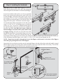
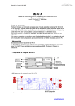
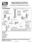
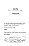
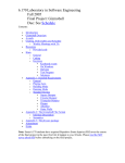
Keyed-in-Handle Autolatch ECR Lock
Installation Instructions
and Owner’s Manual
Wayne-Dalton Corp.
P.O. Box 67 Mt. Hope, OH 44660
(888) 827-3667
www.wayne-dalton.com
All Residential Door Models: 8000/9000 Series & Wood Doors
PHILLIPS HEAD MACHINE SCREWS
(2) 1” (9200) #306564
(2) 1-1/4” (9600/8300 & WOOD)#306565
(2) 1-1/2” (9900) #306566
(2) 1-3/4” (8000/PR9000/8500) #306567
(2) FOAM TAPE
(9200/9600/9900)
3/4” X 2-1/2”
#306653
UNIVERSAL
LOCK STILE
(9200/9600 & 9900)
#261964
OUTSIDE
HANDLE
#255543
LOCK BACKUP PLATE
(8300/8500 & WOOD)
#128564
(2) AUTOLATCH
FLIPPERS
#100287
(2)STRIKER
PLATES #299008
(6) 1/4” -20
FLANGED HEX NUTS
#100279
(6) 1/4-20 X 9/16”
TRACK BOLTS
#200527
INSIDE DOOR HANDLE
#307893
(2) #8 - 32 X 3/4”
PHILLIPS HEAD SELF TAPPING
SCREWS #100278
LOCK CABLE
#307894
(6) 1/4-20 X 11/16”
SELF DRILLING
SCREWS #300723
OR
1/4-14 X 1”
LAG SCREWS
(WOOD DOORS ONLY)
#107584
Required Tools
(1) Electric Drill
(1) 1/8” Drill Bit
(1) 3/4” Dia. Hole Saw
(1) 7/16” 6 Point Nut Driver
(1) 7/16” Wrench Or Socket
(1) Pliers/Wire Cutter
(1) Phillips Screw Driver
(1) Standard Screw Driver
(1) Center Punch
Important Notice!
REFER TO THE DOOR MODEL INSTALLATION INSTRUCTIONS MANUAL FOR
IMPORTANT SAFETY NOTICES.
© Copyright 2003 Wayne-Dalton Corp.
Part No: 307895
New
6/10/03
Step 1: Installing the ECR Lock
CENTER STILE
CAUTION
DO NOT DRILL LOCK
SECTION OR INSTALL LOCK ON DOORS WITH
OPENERS. THE DOOR AND/ OR OPENER MAY
BE DAMAGED IF THE OPENER IS USED WHILE
THE DOOR IS LOCKED.
(3)PRE-PUNCHED
HOLES
NOTE: Common practice for doors with the odd
number of raised panels is to mount the lock towards
the right side of the section when looking out.
(3) 3/4” DIA.
FACE UP
HOLES
FACE DOWN
IMPORTANT: Remove all burrs from the drilled
holes before installing the lock to the section.
8000/8100/8200/PR9000 & PR9050 Series doors (see
Fig.1), place the lock section face down on (2) padded
sawhorses for a single car door or (3) padded sawhorses
for a double car door. Locate the (3) hole pattern in the
center stile of the lock section. Use the (3) holes as a
template to drill (3) 1/8” diameter holes through the
section. Flip the section over, face up. With the section
face up, enlarge all (3) holes to 3/4” diameter, pay close
attention not to drill complete through section into
center stile.
NOTE: Do not drill through or enlarge holes in the
center stile.
Fig. 1
VERTICAL
MARK
HORIZONTAL
MARK
7/16” DIA.
HOLE
(3) 3/4”DIA.
HOLES
1/2 THE
SECTION
HEIGHT
LOCK BACKUP
PLATE
FACE DOWN
Fig. 2
8300/8500 Series & Wood doors (see Fig.2), place the
lock section face up on (2) padded sawhorses for a single
car door or (3) padded sawhorses for a double car door.
Locate the middle of the center stile, measure the distance
from the end of the section to the middle of the center
stile. Turn the section face down, transfer the
measurement and mark a light vertical line, then mark a
horizontal line at half the section height. Align the 7/16”
diameter hole of the lock backup plate at the intersection
point of the horizontal and vertical marks, use the lock
backup plate as a template to mark the (3) holes, remove
the lock backup plate and drill (3) 3/4” diameter holes
through the section.
VERTICAL
MARK
(3) 3/4”DIA.
HOLES
LOCK STILE
FACE DOWN
9000 Series doors (see Fig.3), place the lock section
face up on (2) padded sawhorses for a single car door or
Fig. 3
(3) padded sawhorses for a double car door. Locate the
middle of the center stile, measure the distance from the end of the section to the middle of the center stile. Turn the
section face down, transfer the measurement and mark a light vertical line. Align the center of the lock stile with
vertical mark, use the lock stile as a template to mark the (3) holes, remove the lock stile and drill (3) 3/4” diameter
holes through the section.
2
Step 2: Outside Lock Handle Assembly
8000/PR9000 & PR9050 Series doors (see Fig. 4),
align the outside handle assembly with the handle
pointing towards the floor and insert the assembly
through the previously drilled 3/4” diameter holes in
the section. Secure the outside lock handle to the section
with (2) #10 phillips head screws.
3/4” DIA.
HOLES
OUTSIDE
HANDLE
HANDLE
SHANK
9000 Series & Wood doors (see Fig. 5), align the
outside handle assembly with the handle pointing
towards the floor and insert the assembly through the
previously drilled 3/4” diameter holes in the section.
With the outside lock placed in the section, place the
center lock stile over the shank of the outside lock
handle, secure the center lock stile with foam tape (8300/
8500 Series & Wood doors will use the lock backup
plate with no foam tape). Secure the outside lock handle
to the section by placing the (2) #10 phillips head
machine screws through the lock stile into the lock
section. NOTE: Before proceeding to the next step
its recommended that the outside handle be locked.
#10 PHILLIPS
HEAD SCREWS
HANDLE
FOAM TAPE
SHANK
Fig. 4
OUTSIDE
HANDLE
CENTER
STILE
3/4” DIA.
HOLES
Fig. 5
#10 PHILLIPS
HEAD SCREWS
Step 3: Inside Handle Assembly
8000/8100/8200 & 9000 Series doors (see Fig.6),
position the inside handle over the shank of the outside
handle, flush against the center stile. Align the holes in
the handle with the pre-punched holes in the center stile,
then turn the handle clockwise to secure with (2) #8
screws.
PRE-PUNCHED
HOLES
8300/8500 Series & Wood doors ( see Fig.7), position
the inside handle over the shank of the outside handle,
flush against the lock backup plate. Align the holes in
the handle with the pre-punched holes in the lock backup
plate, then turn the handle clockwise to secure with (2)
#8 screws.
HANDLE
SHANK
INSIDE
HANDLE
CENTER
STILE
(2) #8 SCREWS
Fig. 6
BACKUP PLATE
PRE-PUNCHED
HOLES
NOTE: When securing the inside handle bracket,
be sure not to over tighten the screws or damage to
the inside handle may occur.
NOTE: Follow the Main Installation Instruction
Manual to install the door sections and vertical track
before you install the remainder of the lock parts.
After the sections and track are installed, continue
with Step 4.
SHANK
INSIDE
HANDLE
Fig. 7
3
HANDLE
(2) #8 SCREWS
Step 4: Installing the Autolatch
1
8000/9000 Series & Wood doors (Fig.1-3), locate the
inside handle and uncoil the lock cable, then thread the
cable through the inside handle as illustrated (see Fig.1).
3
Locate the autolatch striker plates over the pre-punched
2
holes in the vertical track nearest the center of the lock
section (see Fig.2). Fasten the striker plates to the vertical
track using (2) 1/4-20 x 9/16” track bolts and flanged hex
nuts. Align the autolatch flippers such that the arm will
engage the striker plates. Position the autolatch flipper
1/8” from the edge of the section and secure it to the section
with (3) 1/4 -20 x 11/16” self drilling screws (wood doors
4
will use 1/4-14 x 1” lag screws). Bend the bottom edge of
the Autolatch flipper arm away from the door slightly for
smoother operation (On 9900 Series doors, bend the
autolatch flipper toward the striker plate until it is able
to engage (see Fig. 3). Feed one end of the lock cable
through the slotted hole of an Autolatch flipper and secure
Fig. 1
with (1) 1/4-20 x 9/16” track bolt. Pull the cable taut, but
not enough to lift the flipper out of the striker plate. While holding taut, feed the lock cable through the slotted hole
of the remaining Autolatch flipper, secure with (1) 1/4-20 x 9/16” track bolt and flanged hex nut.
NOTE: Ensure that the bolt is through the front of the flippers and the nut is on the back of the flippers
with cable going through the front of the flippers.
Operate the lock several times to make sure the Autolatch flippers clear the striker plates when the handle is turned
and the flippers engage the striker plates when the handle is released. Adjust the cables if necessary. Trim off the
excess cable with wire cutters after the lock is operating satisfactorily.
TRACK
FLIPPER
VERTICAL TRACK
1/4-20 FLANGED
HEX NUT
STRIKER
PLATE
AUTOLATCH
FLIPPER
Fig. 3
INSIDE
HANDLE
1/4-20 X 11/16”
SELF DRILL SCREWS
1/8” OFFSET FROM
EDGE OF DOOR
1/4-20 X 9/16”
TRACK BOLTS
STRIKER
PLATE
Fig. 2
4
USE PLIERS TO BEND
LOCK ARM SLIGHTLY