1
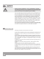
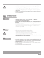
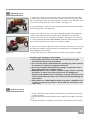
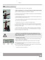
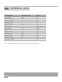
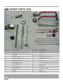
USER’S MANUAL Carefully read entire manual before operating the firewood maschine! Setup & installation use Maintenance accessories HYDRAULIC LOG SPLITTER THS 4 Südharzer Maschinenbau GmbH Helmestraße 94 ∙ 99734 Nordhausen/Harz Receptionist: 03631/6297-0 ∙ -111 Internet: www.bgu-maschinen.de e-mail: [email protected] CONTENT 1. 2. 3. 4. 5. 6. 7. 8. 9. 10. 11. 12. 13. 14. 2 General information 3 Product overview Warning label and safety decals on the machine Safety 5 6 8 1.1 About the manual 1.2 General information 1.3 Delivery and transport claims 4.1 4.2 4.3 4.4 General safety rules 8 Personal safety Compliant use Electric safety 3 3 3 10 10 10 Operation 11 Repairs and maintenance 14 Dismounting and disposing an obsolete machine Other areas of possible danger 16 16 Partial warranty Full warranty Technical data Troubleshooting Spare parts list EC Statement of compliance 17 17 18 19 20 21 5.1. 5.2. 5.3. 5.4. 5.5. 5.6. 5.7. 5.8. 6.1 6.2 6.3 6.4 Machine placement Start-up Electric specs Hydraulic specs Operating your log splitter Splitting tips Splitting cycle End of the work Ordinary periodic maintenance Sharpening the splitting wedge Hydraulic oil specs Changing the hydraulic oil 8.1 Mechanical dangers 16 8.2 Electric dangers 11 11 11 12 12 12 13 13 14 14 14 15 16 1. INTRODUCTION Dear customer, thank you very much for your trust and preference in choosing our equipment and joining the number of our best customers in the world. We are confident that our equipment will be up to all your expectations and assure you a long lasting quality and performance. Please read this manual before the installation and the startup of this equipment! 1.1 About the manual 1.2 General information Please take time to read this manual and learn to how operate and maintain the splitter safely. For your easier reading this manual is laid out in several sections. The sections are progressively numbered 1 through 24 and listed on the “content” page. The information, pictures and technical data in this document reflect current or planned product features, functions, and characteristics as of the publication date. Because of on-going product improvements and feature additions, information in this document is subject to change without notice. If you are experiencing a problem or functional trouble on your machine, please read the “trouble-shooting” section to identify possible causes and remedies.If the problem or functional trouble is not listed in the troubleshooting chart contained in this ma-nual, ask your Authorized Service Centre for service. When you have checked all the possible causes listed and you are still experiencing the problem, ask your Authorized Service Centre for help.When you order parts maintenance or repair services, your Authorized Service Centre, your dealer or eventually the manufacturer need your machine serial number and engine serial number.These are the num-bers that you have recorded on the product identification label of the manufacturer on the machine. This manual contains some of the most important safety warnings which must be read and understood before the installation and startup of the equipment. It also contains important instructions that will help you optimize the operation and the lifetime of your machine. 1.3 Delivery and transport claims Upon delivery of the machine please inspect the machine if any parts are damaged such as damaged packing or scratched buckled parts. If so, make a remark on all copies of the delivery bill before signing for acceptance. 3 Scope of delivery: • 1 fully assembled log splitter • 1 User‘s manual • 1 Control lever Also have the truck driver sign al copies of the delivery bill. Should your shipper or the truck driver refuse to accept your claim, fully reject delivery and make sure to inform us (the manufacturer) immediately. No claims shall be taken into account by the shipper or by the insurance company, if a reservation note is not made on the delivery bill. All transport damages must be notified within latest 2 days from delivery. Therefore delivery must be collected and inspected within this term. Later claims shall be disregarded. In case of assumed but not visually clear transport damages make sure to mark the following sentence on the delivery bill: „Reserved delivery due to assumed transportation damages“. Insurance and shipping companies act with extreme caution in case of transport damages and sometimes refuse to accept responsibility. Please make sure to provide clear and exhaustive evidence (photos) of the claimed damages.Thank you in advance for your help and attention to this matter. 4 2. PRODUCT OVERVIEW Log splitter main parts and controls: Splitter wedge Push-block Cylinder cover Control handle Piston rod Oil gauge ON/off switch Lateral guides Air bleed screw Electric motor 5 3. WARNING LABEL AND SAFETY DECALS 1. Operation safety label Warning label „Read before use“ Never operate the machine without reading or understanding the operator’s. 2. Operation safety label Safety decal “WARNING! Always wear safety shoes”. Wearing safety shoes is advisable and particularly for continuous operation of the machine 3. Operation safety label Safety decal “WARNING! Always wear safety gloves” Wearing safety gloves is advisable and particularly for continuous operation of the machin. 4. Operation safety label Safety decal „Wear ear plugs and goggles“ Loud noise can cause impairment or loss of hearing, wear a suitable protective device such as ear plugs or goggles. 5. Operation safety label It is strictly forbidden to run the machine without its safeties and protecions, to bypass or to modify them. 6. Operation safety label Warning label KEEP BYSTANDERS AWAY „5 meter dangerous aera!„ Do not let bystanders, children or pets approach the machine and stand within the dangerous area during operation. 7. Operation safety label „DANGER! Pinched hands danger!“ Keep your hands away from all moving parts! Pinched handsdanger. 8.Operation safety label Danger! Moving part!Mind the splitting wedge and keep your hands away while it works. 9.Operation safety label DANGER! Never try to clear a jammed log with your hands! 6 10. Operation safety label Before setting-up, servicing, maintaining and cleaning the machine, disengageall power and stop the engine. 11. Operation safety label Stop! Read, understand, and follow all instructions in this manual and bleed residual air out of the hydraulic lines before starting! (see page 12). 12. Identification label „Product Identification“ This label shows the company details of the manufacturer and the main machine technical data. 13. Identification label with „BGU-Maschinen“ logo“ The following warning symbols are used in this manual with this meaning: WARNING This symbol precedes a general CAUTION or WARNING state ment. Where you see this alert symbol and WARNING heading, strictly follow the warning instructions to avoid personal injury A „notebook“ symbol precedes an important istruction mean to facilitate and otpimise working with the machine. Product/Packing Disposal Symbol Electric components ma y not be disposed with your home waste. Electric wares, their accessories and their packings must disposed in accordance to the environmental/waste disposal rules of your country. 7 4. SAFETY Strictly perform installation, set-up, maintenance, cleaning and transport with the motor switched off and the blade firmly secured against accidental operation.Immediately disconnect power off in case of any eventual fault or trouble. The user shall comply with these operation, set-up, maintenance, repair and trouble shooting instructions in order to assure safe operation and no damages to the equipment. Moreover we recommend letting the machine be run only and strictly by trained and skilled staff that must be familiar with the applicable occupational safety and health administration rules as well as applicable transportation rules. Machine instability can result in injury or severe damages. To ensure stability during operation make sure to choose a flat, dry floor free from any tall grass, brush or other interferences. The working area around the machine must be kept as clear as possible from surrounding obstacles and slippery foundation floors should be duly treated (do not use saw dust or wood ash for this purpose). Make sure that the equipment stands on a safe stable foundation. 4.1 General safety rules Following precautions must be taken at all times: ● Only skilled competent persons may be assigned to operate the machine. No one under the age of 18 should be allowed to operate the log splitter. ● Do not allow within the hazardous zone any unauthorized thirds or persons who are not familiar with the dangers related to use and operation of the machine and do not perform uncompliant use of the machine. REMEMBER: the operator is responsible for safety of all nearby thirds on site. ● Operators must wear steel toe safety shoes and snug-fitting tear-resistant work cloths. ● Operators must wear hearing protection, safety glasses, safety shoes, helmets, gloves and other adequate protection means. ● Wear protective hair covering to contain long hair during operation. ● Always comply with these instructions when your start/operate the machine. • NEVER leave the machine unattended with the running motor. Before switching power on and putting the winch to work make su re that there are no bystanders in the dangerous area and that you have good and clear visibility on the work area. 8 ● Before operating the machine for the first time inspect and test all safetiesand protection devices (i.e. Two-hands control lever, hand guards etc...) and safety stops. ● After switching the machine on and before starting to work make sure that all parts and controls are duly functioning and in place. ● Set up the machine on a firm surface and ensure that a wide but confined area is available around the machine assuring maximum working freedom. ● NEVER use the machine for other applications than described under the sections „applicable use“ and „operating your splitter“. ● Machine instability can result in injury or severe damages. To ensure stability during operation make sure to choose a flat, dry floor free from any tall grass, brush or other interferences. ● Never stand behind the push-block or near the control handle while the machine is running. Never reach inside the dangerous area around the splitter wedge. ● Refrain from working with the log splitter if you are too tired or un der the effects of drugs, alcohol or other medicaments. ● Keep your workplace tidy and as clear as possible from surrounding obstacles to avoid dangerous situations for your own safety! ● Due and proper illumination of the working site must be provided at all times. Avoid overlaoding your machine. ● Never modify or add parts to the machine. ● DANGER! Do not operate and do not park the machine in rainy wea ther. Always operate/store in a dry rooms away from children reach. ● Switch the machine off and disconnect power before: - Transportation - Repairs and adjustment works - Troubleshooting operations - Cleaning and maintenance works - leaving the unit unattended (even for just a short time) ● Inspect the machine and fix eventual damages or anomalies before continuing to work with it: - all guards must be in faultless state and conditions before starting to work. - all parts must be free of faults and defects and duly seated in their place on the machine - Eventual defective or damaged guards and parts must be repaired or replaced with new original ones by a skilled technician or an authorised service centre, unless other instructions are given in this manual. ● Replace safety labels on the machine as they become tore or not readable any longer. 9 4.2 Personal safety Wear the following mandatory personal safeties while operating the machine: ● Summer/winter safety gloves ● Safety glasses/goggles ● Ear plugs or muffs ● Snug-fitting work clothes ● Steel toe safety shoes 4.3 Compliant use • The log splitter is strictly designed for residential users splitting short firewood at home. • Always split straight logs and grain-wise. Never split more than one log at a time. • Metal parts (wires, nails etc...) must be removed before splitting. • No other use is permitted and shall be considered as uncompliant. The manufacturer is not liable for damages/injuries caused by eventual uncompliant use for which the operator will be solely responsible. Lack of compliance with these instructions may lead to dangerous risks and situations and will void all warranty claims, in which case the manufacturer will not be responsible for customers’ claims or resulting damages and/or injuries. 4.4 Electric safety 10 • Use IEC power cords 60245 (H 07 RN-F) with at least 2.5 qmm section of the cables up to max 10 m length. • Do not use extention cords longer than 10 m, that may cause undesired voltage loss whereby the motor cannot reach its max power. • Install and connect the machine so to avoid possible squeezing, crimping and folding of the cable and to prevent the plug from getting wet. • Protect the cable from any heat source, oil contact and sharp obejcts. Never use electric power cable for any other application and never pull the cable to unplug the machine. • Never use defective or damaged connection lines and periodically check the state of the extention cables. • If you are using the machine outdoors make sure to strictly use connection materials approved for outdoor application. • Never make use of temporary electric connections and never bypass/remove the safeties built by the manufactuer in the machine. • A skilled licensed electrician must be asked for any repair of the electric system. Strictly perform electric connections in compliance with the applicable rules of the country. • Strictly use original parts. DANGER : the manufacturer is not re sponsible for damages/injuries caused by the use of non original spare parts. • Repairs of any other part of the machine may be strictly performed by the manufacturer. 5. OPERATION 5.1. Placement 5.2. Start-up 5.3. Electric specs • Install the splitter on a 60 - 75 cm high table, to obtain an ergonomic and safe working position. • Provide a flat, clear working surface and due, proper illumination of the room. • Never operate a log-splitter near diesel oil, fuel, gasoline or other flamable materials. • The working area around the machine must be kept as clear as pos sible from surrounding obstacles and slippery foundation floors should be duly treated. • Before you start working with the log-splitter: - inspect the conditions of the connection lines - inspect the machine to detect eventual visible damages - check the correct tightness of all screws and - check the hydraulic system for eventual leaks • Check the general conditions and make sure that the splitter is duly assembled with all its parts and fittings. • Check the compliance of your network power specificationss with the ones of the identification label and plug the machine to a compliant approved socket. • Strictly use extension cable of the correct section. • Provide connection to the network by ways of a 30 mA RCD (residu al current device). • Required domestic overload safety is 16 A. 11 5.4. Hydraulic specs • NEVER operate your splitter in case of suspected oil leaks or hydraulic troubles. Check all hydraulic hoses, fittings and couplings to de tect and repair eventual oil leaks. Do not check for leaks with your hand. • Choose a flat, dry, and solid location to operate your splitter. Make sure that the area is free of slippery surfaces and objects to trip over. Slippery and icy floor conditions must be duly treated. • Periodically check the oil level inside the hydraulic oil tank. (See maintenance section) 5.5. Operationg your log splitter • On/Off switch Press and hold the green push-button down to switch the unit on. The motor keeps running till you keep the push-button pressed down. The motor stops at once, as soon as you remove your finger and clear pressure from the push-button. • Press the push-button down and wait a few seconds for the motor to reach its max speed and for regular operating pressure to be established in the machine. Then press the control button down as you concurrently hold the on/off switch engaged. (see picture 1) • While doing this, the push-block starts advancing the log to and through the wedge to completely split it in two pieces. Release the control handle and the control button at once to trigger the back travel of the ram making the push-block return to start position. Figure 1 5.6. Splitting tips Release Figure 2 12 Clamp • Initial checkups Make sure that your logs are max : • 370 mm long • 50 - 250 mm diam Accurately select your firewood making sure to strictly process quite clean and straight logs. DO NOT TRY to split short but crooked chunks on this machine. The location you choose for your machine should be flat, dry, solid and with sufficient clearance. • Safety air-bleeding Release the air-bleed screw by 3 or 4 turns (Figure 2). Do not tighten the screw till you are finished with your work. IMPORTANT! make sure that the screw is tightened before you handle the machine for further transportation. 5.7. Splitting cycle • Load your chunk on the machine laying it firmly between the later al guides and against the push-block. Always split the log grain-wise. Do not attempt to split the logs standing vertical on the machine. The log must be secureley laid in the cradle. (see figure 3) • Do not attempt to split with the log skewed across its seat betweent the lateral guides. (see figure 4) Figure 3 Figure. 4 • Make sure that the log is securely clamped between and perpendicular to the wedge and to the push-block. NEVER try to split two chunks at a time. If the log tends to wobble, reposition it by turning it. This operation MUST BE PERFORMED with the machine stopped af ter all moving parts have come to a complete STOP. • Never try to hold the pressure up for a longer time to force a big log through the wedge. Doing this may cause dangerous overloads that may damage the machine. In this case stop the machine, turn the chunk around and try again. Clearing logs sticking to the wedge: • Clear both control but tons and control handle to let the push-block return to start position. • Fit a wooden block underneath the sticking log, then operate the pusher to advance it against this block. • If the log remains attached to the wedge, repeat the proce dure using each time a bigger block. • DANGER! Never try to clear a jammed log by hand or by ham mering on it. Keep you hand away from the dangerous wedge area! Hammering or hitting on a jammed log may cau se strong shocks that may cause even permanent damage to the motor! • This splitter is a ONE-MAN operation machine. NEVER let more than one person operate or work with the machine at the same time. 5.8. End of the work • At the end of the work, make sure that the push-block drives back to start position • Unplug the machine and tighten the air-bleed screw again (see figu re 2) • Provide consistent compliance with these maintenance instructions. 13 6. REPAIRS AND MAINTENANCE Make sure that the machine is fully disconnected and all moving parts are secured before performing any maintenance/repair work on the machine. In the event of any malfunctioning, switch the machine off before trouble-shooting. 6.1 Ordinary periodic maintenance Make maintenance a regular part of daily operation. The daily maintenance routine needs to include: • Cleaning of the machine and clearing of all parts from residual wood debris, chips, dust, bark pieces and eventual other waste. • Greasing of the piston rod pads inside the splitter stand. • Hydraulic oil check and (in case of leakage) hydraulic hose and fittings check-up to detect eventual oil leaks. • Lubrication of all moving parts. • Always wear protective no-tear gloves when performing maintenance works on the machine. 6.2 Sharpening the splitting wedge A dull wedge profile will immediately lead to a poor splitting quality. For this reason the wedge must be regularly grounded using a fine grinding file. Makes sure to remode chips and dust before using the splitter again.(see figure 5) (Fig. 5) 6.3 Hydraulic oil specs Periodically check the oil level inside the hydraulic oil tank. When doing so, accurately avoid contaminating the tank with dirt, wood chips, sawdust etc... Make sure that the splitter never runs without oil or with a low oil level. When this happens, air is likely to reach inside the hydraulic loop. Failure to maintain due oil level may cause poor running and irregular splitter operation (very rough, back/forth or up/down motions) as well as major pump damages. Perform the first oil change after approx 50 operation hours and then againg every 250 operation hours or once a year. The oil drain plug is located underneath the oil tank while the oil filler is located on the upper right-hand-side of the tank. Recommended oil types: Aral Vitam Gf 22, Shell Tellus T22, Mobil DT1,BP Energol HLP 22 Code Nr. 400142 (1 l) or equivalent ones Never allow use of other types of oils. DANGER : other oil types may not be suitable for the machine and effect proper functioning of the hydraulic ram. 14 Abb. 5 6.4 Changing the hydraulic oil • Drive the push-block back to start position. • When changing the oil, never let used oil drop down on the ground, rather collect whole of it in a sealed container for due disposal. Oil disposal containers should be of at least 4 l capacity. • Release and remore the oil dipper rod and pull it without extracting the oil gasket (Figure 6). • Tip the splitter over and set it upright on its wheeks to drain the oil out of the pressure lines. (Figure 7) Figure 6 • Then tip the splitter over again till the oil filler is facing up. This is a very easy one-man operation! • Fill the new oil in (2.7 l) using a new clean funnel. • Clean both the dipper rod and the oil gasket making sure that the gasket is tightly in place. Worn out gasket should be replaced before starting to work again. • Secure the dipper rod tightly in place avoiding to apply excessive torque on the screw and therefore to avoid damaging the oil gasket and the thread of the cylinder cap. Figure 7 • Used oil is very polluting and should be disposed in accor dance with local rules! Do not spill nor dispose used oil with other domestic waste. • Checking the oil level - Unscrew and pull the dipper rod out, clean the rod and the gasket (broken gaskets to be replaced). - Dip the rod back in down to the stop and then pull it out again. Lower mark Upper mark Rubber seal If the oil level is between the two marks, it means the oil level the tank is enough. If the level hardly reach the lower mark, then you need to top up oil in the tank using a new/clean funnel. - Dip and screw the rod back in. 15 7. DISMOUNTING/DISPOSING THE MACHINE When the splitter is fully obsolete and cannot be of any longer use, it should be duly dismounted ahead of discarding. Certain componentsneed deactivation and dismantling in order to assure that no further use is made by other parties and that no worn out parts are recycledfor other applications. During dismantle be alert for possible recyclable materials and components that belong to differentiated waste collection procedures applicable in your country. The manufacturer is not liable and undertakes no responsibility forpersonal injuries or damages that may result from the recycling ofworn out machine parts for eventual re-use in other applications different than originally stated in this manual. Dismantling procedure Take good note please: each and every dismantling task must be performed by authorized service centres or trained skilled staff only! • Pull the machine down into single components • Lock and clamp all moving machine parts • Deliver each single component only to authorized waste management facilities Deactivated, clamped moving/driving parts and components are of no further risk and danger. 8. OTHER AREA OF POSSIBLE DANGER 8.1 Mechanical dangers All moving parts on the machine (hammers and V-belt) are protected by permanent safety guards minimising risks and dangers related to moving parts on the machine. No accidental removal of the guards will be possible, as special tools will be required to dismount them. WARNING: operating the machine without the safeties will increase your risk of getting injured. 8.2 Electric dangers All machine parts staying under voltage are duly insulated or sealed inside a fixed casing to avoid accidental contact. For safety reasons all fixed casings can be only removed using special tools and equipment. WARNING: removing a fixed protection casing when the machine is running or without having priory cut the power off, may result into major danger of electrical shock! 16 9. PARTIAL WARRANTY All our machines are covered with warranty terms in accordance withthe law. Customers should promptly notify the manufacturer eventualmaterial or production claims on their detection. While asking for warranty service, customer should show copy of their purchase invoice or receipt. The warranty does not cover for faults due to natural wear, temperature or weather agents as well as misuse, faulty installation or set-up, improper operation and lubrication or acts of vandalism. No warranty will be given on parts damaged by improper handling, use and application. The manufacturer is further not responsible for warranty service on machines used for other applications than mentioned in this manual, altered or modified by the customer or other thirds, or overloaded. Never attempt to use an incomplete machine or one fitted with unauthorized modification. Any modifications to your machine can cause personal injuries, and will void your Warranty. Consumable parts with a prescribed life (i.e. pulleys, tools and various auxiliary materials) are excluded from the warranty as well as adjustment, optimization and fine-setting or retrofitting works. 10. FULL WARRANTY All SŰMA equipment is covered with 24 or 12 months total warrantyfrom the date of purchase for private/industrial users and rentals.The total warranty does not substitute nor void the legal warranty.Customers should promptly notify eventual material, production orworkmanship claims on their detection. While asking for warranty service, customers should show copy of their purchase invoice or receipt. Buyer’s address and type/model of equipment must be clearly statedin the case of industrial users/contractors/dealers. All claims relatedto material or production failures during the total warranty time, shallbe repaired notwithstanding eventual user’s faulty/wrong operation or maintenance. 17 11. TECHNICAL DATA Technical data Measuring unit THS 4 Log capacity mm 350 Min. log diameter mm 50 Max. log diameter mm 250 Splitting power t 4 Motor power P1 kW 1,5 Rated voltage V 230 - 50 Hz Motor speed 1/min 2820 Rated current V 8,5 Machine heigth mm 480 Machine width mm 360 Machine length mm 810 Machine weight kg * Spaltkraft kann um ± 10% schwanken. l Oil capacity (Tank) 41 2,7 * The actual splitting force may vary ± 10% of the nominal rating 18 12. TROUBLESHOOTING CHART Type of malfunction Possible origins of the problem Solutions Cannot split the log (insufficient splitting power) • Chunk is malplaced • Chunk is too long or its hardness exceeds the capacity of the machine • Wedge is worn out • Relocate and settle the chunk • Reduce the chunk to admissible dimensions • Grind the wedge. Remove dust and chips from the machine • Do not check for leaks with your hand. Leaks can be located by passing a piece of cardboard or wood around the suspected leak and looking for discoloration. Let the manufacturer fix eventual leasks. • Check the oil level and top up if required. Contact the manufacturer if the problems remains or occurrs frequently. • Use admissinle connections • Search for possible oil leakage • Hydraulic pressure is too low • Connection faults (power line/extension is longer than 10 m or the section is too small) Push-block sways and wobbles or strongly vibrates as it advances. • Residual air in the hydarulic lines • Remove air bleed screw • Check the oil level and top up if required. Contact the manufacturer if the problems remains or occurrs frequently. Push-block does not start • Faulty hydraulic pump. • Contact the manufacturer. Motor does not start • No power or power blackout • Defective motor • Check your overload safety valve (16A) • Invert the cable connections or let a skilled electrician check the machine. • Contact the manufacture. • Dipper oil gasket is worn out • Replace the gasket • Fault power cable Oil leaks out of the dipper rod 19 13. SPARE PARTS LIST 5 9 10 17 8 21 22 14 16 19 11 12 7 20 2 18 6 15 13 1 3 +4 Pos. Nr. Description Pos. Nr. Description 1 Dipper rod 12 Piston rod 2 Oil gasket 13 Stop rod 3 Air bleed screw 14 Motor with on/off switch 4 Seal for air bleed screw 15 Push block 5 Lateral (log) guides 16 Spring 6 Upper plastic pad 17 Set of keys & spares for drain plug 7 Lower plastic pad 18 Motor cover 8 Connectors 19 Fan blade 9 Control handle 20 Push-block guide 10 Wheels 21 Piston 11 Cylinder 22 Wedge slider 20 14. EC STATEMENT OF COMPLIANCE to the EC Machines Directive No. 2006/42 EG We hereby declare that the equipment described in this manual responds in full to the actual version brought on the market. We, the manufacturer further declare that this equipment was duly designed and manufactured in accordance with the actual European Safety and Health Standards settled by the relevant EEC directives as well as the latest electromagnetic standards issued by the European Council of 3.5.89 and later enforced by all member states.This statement of compliance does not apply to customer modifications of the equipment without manufacturer’s written approval. Machine type: Log Splitter Model: THS 4 Production number: See manufacturer‘s plate Applicable European Standards: EEC Machine Directive Nr. 2006/42 EG EEC Low Voltage Directive (93/68 EWG) 2006/95/EG EC EMV 2004/108 Other applicable Standards Full compliance to the European safety rules was assured by enforcement of the following harmonised Standards : EN 574; 1996 + A1 -2008 EN 609 -1; 1999 + A2 -2009 EN 55014-1:2006 EN 55014-2:1997+ A1:2001 EN 61000-3-2:2006 Person responsible for the tecknical documents: Jörg Kernstock (Director) 04.12.2006 Date Jörg Kernstock (Director) Official user language: English (User’s release) 21 22 23 Südharzer Maschinenbau GmbH Helmestraße 94 ∙ 99734 Nordhausen/Harz Service-Tel. + 49(0)3631/6297-104 Fax + 49(0)3631/6297-111 Internet: www.bgu-maschinen.de e-mail: [email protected] 24 Subject to changes and further modifications Form: 2007.04.12.2010 - Rev. B