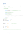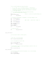
1
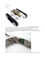
Autonomous Vehicular Trailer
EE 452 Final Project
Spring 2012
Conor Cahill, Steven Hopkins, and Adam Morse
Abstract
Today’s vehicles with cruise control typically lock the speed to a fixed set point. Problems arise when
the speed of the lead traffic varies, causing the drivers to have to manually adjust the set speed. A
simple addition of a distance sensor opens up the possibility to follow the leading vehicle and
maintain a fixed safe distance. This project implements one such method of following a lead vehicle
using an ultrasonic distance sensor to measure the distance. A microcontroller plus code contain the
algorithm necessary to adjust the power of the motors to maintain the proper distance. In the future,
this algorithm could be expanded to take other variables into account, such as requested speed and
collision avoidance.
Table of Contents
Introduction ...................................................................................................................................................................2
Technical Approach .......................................................................................................................................................3
Block Diagram ................................................................................................................................................... 3
Software Systems.............................................................................................................................................. 4
Algorithm ...................................................................................................................................................... 4
Source Code ................................................................................................................................................ 10
Hardware Systems .......................................................................................................................................... 42
Hardware Description ................................................................................................................................. 42
Schematics .................................................................................................................................................. 43
Test Plan and Results ...................................................................................................................................................48
Conclusions ..................................................................................................................................................................52
References ...................................................................................................................................................................53
Appendixes ..................................................................................................................................................................54
Time Tracking .................................................................................................................................................. 54
User Manual .................................................................................................................................................... 55
Datasheets ...................................................................................................................................................... 58
Rover 5 ........................................................................................................................................................ 58
Motor Driver: Freescale MC33926.............................................................................................................. 60
Ultrasonic Distance Sensor: MaxBotics XL-MaxSonar-AE4 (MB1340) ........................................................ 85
MCU: Microchip PIC18F46K22 (Partial) ...................................................................................................... 90
Buzzer: Mallory AST1240MLTRQ ................................................................................................................ 94
Introduction
An Autonomous Vehicular Trailer is a vehicle designed to be a trailer that follows behind a lead
vehicle adjusting its velocity as necessary to maintain its relative position with the lead vehicle. This
trailer is autonomous in that there are no direct communications/controls from the lead vehicle to
the trailer. The trailer itself senses the location of the lead vehicle and adjusts its own velocity to
automatically follow behind the lead vehicle.
We will construct the trailer using a kit-based tracked vehicle with two DC motors (one for each
track) connected to a motor control unit that is, in turn, controlled by our PIC18 microcontroller. In
addition we plan to use an ultrasonic sensor to determine the distance between the trailer and the
lead vehicle and LED indicators to represent “hazard” lights.
The trailer will only adjust itself to movement in a straight line direction. It will not turn to follow
the lead vehicle should the lead vehicle turn. If the trailer does not sense the lead vehicle, or loses
track of the lead vehicle, it will stop and turn on its hazard lights and await the return of the lead
vehicle.
The software control will continuously monitor the distance between the lead vehicle and the trailer
and will use this information to also calculate the relative velocity and relative acceleration. In
addition separate wheel sensors will be used to monitor the absolute velocity of the trailer. The
absolute velocity of the trailer will be used to define a target distance range for the trailer (getting
higher as the velocity increases to allow for additional response distance).
The distance, relative velocity and relative acceleration will be used to control the power provided
to the motors in order to control the acceleration of the trailer in an efficient manner. We plan to
use a proportional-integral-derivative (PID) algorithm to determine the amount of power to send to
the motors in order to maintain the appropriate distance from the lead vehicle. The motors will
also be used to provide braking force when necessary in order to maintain the appropriate
separation distance when the lead vehicle slows abruptly.
We plan to support both positive and negative velocity so that the lead vehicle can move forward
and/or backward and the trailer will maintain the appropriate separation distance.
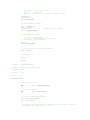
Technical Approach
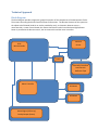
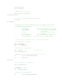
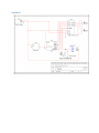
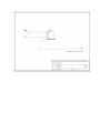
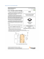
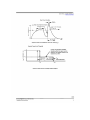
Block Diagram
The block diagram provides a high-level, graphic illustration of the components of the Autonomous Trailer.
The arrows connecting the blocks illustrate a flow of information. The discrete elements of the system are
the object to be followed (Lead Car or similar provided by user), an ultrasonic distance sensor, a
microcontroller, a motor control board, the motors that drive the vehicle and the hazard lights/buzzer.
Power is provided to the distance sensor, the microcontroller and the motor controller.
Distance
Sensor
8-Bit
Microcontroller
Power
Manually Controlled
Lead Car with
Reflective Tape
Motor Controller
DC Motor1
DC Motor2
Hazard Lights (LED Array)
Backup beeper (buzzer)
Software Systems
Algorithm
We have broken our algorithm and functionality into several pieces of functionality tied together by our main
function. The algorithm for each component is discussed separately.
Main Loop
Sensor Control, Pseudo-code
; Algorithm for initializing and reading ultrasonic distance sensor
;
; Parameters: None
;
; Outputs:
WREG and ADRESL will contain a regularly updated 8-bit value representing distance
; in cm (1 bit per cm)
;
; Global Data: Oscillator will be configured to 16MHz
;
; Persistent Data: When bits 0 or 1 ADRESH are set, this indicates a distance sensor error, and
; error code WREG=0xFF
;
is given
;
; Temporary Data:
;
; Algorithm
;**********************************************************************
;
; Initialize Sensor
initSensor() {
;Set TRISA (pin RA2) to input and ANSELA (pin RA2) to configure analog
TRISA <-- set bit 2
ANSELA <-- set bit 2
;Configure ADCON0, ADCON1,ADCON2
;ADCON0 (comments move right to left from LSB, ignoring unused bits)
;ADON<0> -- 1 -- initialize ADC
;CHS<4,0> -- 00010 -- Channel select AN2
ADCON0 <-- B'00001001'
;ADCON1
;PVCFG <1,0> -- 00 -- positive voltage reference set to MCU internal 5V
;NVCFG <1,0> -- 00 -- negative voltage reference set to MCU internal 0V
ADCON1 <-- B'00000000'
;ADCON2
;ADCS<2,0> -- 010 -- Assume TAD>=1.6microsecond (from lecture),
;and MCU 16MHz device frequency, therefore use Fosc/32 as the ADC clock
;source (giving a period of 2microsecond, p299)
;ACQT<2,0> -- 100 -- If we assume maximum temp of 50C, utilizing TACQ
;formula, there is a still good deal of variation depending on the sensor
;impedance (unknown at this point). But based on a 2.5kohm impedance, the
;text (p577) calculates TACQ=~13microsec. To be conservative, we can use
;8*TAD
ADFM -- 1 -- right justify results in ADRESL/ADRESH
ADCON2 <-- B'10100010'
}
;Read Sensor Value
readSensor() {
; Begin acquisition/conversion sampling loop
;
; Start conversion
ADCON0 <-- GO ; set GO bit
;
; Test if conversion is finished before proceeding
If ADCON0 <GO/DONE> = 1
(
Return to test again with branch loop
}
;
; Test for system error by testing ADRESH value
; If bits 0 or 1 are set, then WREG must give error code 0xFF
; If there is no error, place ADRESL into WREG as returned value
If ADRESH <0> = 1 { ; poll for errors in the first bit of ADRESH
WREG <-- 0xFF ;
set error code
}
Else {
WREG <-- ADRESL
}
If ADRESH <1> = 1 { ; poll for errors in the first bit of ADRESH
WREG <-- 0xFF ;
set error code
}
Else {
WREG <-- ADRESL
}
; Delay 2TAD before returning to readSensor start
}
Motor Control, Pseudo-code
;
; MotorControl.txt - pseudocode for MotorControl functions
;
MotorInit - called to initialize the Motor Control system
;
; We are using a PWMs to control each motor and need to
; configure them for our use and for our motors
;
Set the period Register for Timer 2 to be 66 (which gets us a 15Khz PWM freq)
Configure CCP1 and CCP2 on Port C for output
Enable Timer2 and set it's pre-scaler to 4 (so our input is (16M/4)/4 or 1Mhz)
Associate Timer2 with PWM1 and PWM2
Enable PWM Mode on CCP1 and CCP2
Configure pins 7-3 on PortC for output
Set the motor to off
end
MotorUpdate
- called to update the motor settings
;
; Parameters:
Arg1 - the desired motor power percentage (0-100)
;
Arg2 - the desired direction (1=reverse, 0=forward)
;
Set the motor duty cycle to the value from Arg1 on Motor 1 and Motor 2
If the desired direction is forward
set MotorSettings to Forward
clear Reverse status indicator
else
set MotorSettings to Reverse
set Revers status indicator
endif
write the new MotorSettings to PortC
end
MotorEmergencyStop - called when we've lost track of Lead Vehicle
Set motor duty cycle to zero for both Motor 1 and Motor 2
Set MotorSettings to OFF
write the new MotorSettings to PortC
end
Process Data, Pseudo-code
;
; ProcessData.txt - algorithms for ProcessData subroutines
;
ProcessDataInit - called at start of program and to reset ProcessData
Initialize ProcessData variables to zero
end
ProcessDataLost - called when lead vehicle is lost
Call ProcessDataInit to initialize variables
end
ProcessData
Save parameter to SensorDist
Get our previous return values and set new return values to same values
if the motors are stopped
if the lead vehicle is beyond target range
save distance to target (SensorDist-TargetHigh) in DistOff
set direction to forward
else if the lead vehicle is below target range
save distance to target (TargetLow-SensorDist) in DistOff
set direction to reverse
else (the vehicle is within target range)
set NewMotorPower to zero
endif
if we are adjusting power (beyond or below)
;
; now to adjust power
;
If we are within the low power adjustment range (< 5cm)
set NewMotorPower to (1*DistOff) (e.g. 1%/cm)
else
set NewMotorPower to (2*DistOff) (e.g. 2%/cm)
endif
if NewMotorPower is greater than max allowed (20%)
set NewMotorPower to 20%
endif
endif
else (the trailer is moving)
;
; calculate some needed values for our operations/comparisons
;
set DistChange to how far we've moved since last call
set DistHigher flag to tru if our new distance is greater than prev dist
set DistZero
flag if our new distance is exactly the same
set DistOff
to the difference between our current distance and target distance
set TgtBelow
if we are below target distnce
set TgtExact
if we are exactly the target distance
set CloserTgt if we are closer to target than we were before
if we are not on target or distance has changed
if moving forward
if we are too close (TgtBelow == true)
set ReducePower flag
esle if we aren't closer than we were before
set ReducePower flag
else if we aren't catching up to correct position quickly enough
set IncreasePower flag
else
set PowerOK flag
endif
else
(we are moving backward)
if we are too close (TgtBelow == true)
set IncreasePower flag
else if we aren't getting closer than we were before
set ReducePower flag
else if we aren't catching up to correct position quickly enough
set IncreasePower flag
else
set PowerOK flag
endif
endif
if IncreasingPower
If we are within the low power adjustment range (< 5cm)
set power increment to (1*DistOff) (e.g. 1%/cm)
else
set power increment to (2*DistOff) (e.g. 2%/cm)
endif
if power increment is greater than max allowed (20%)
set power increment to 20%
endif
add power increment to NewMotorPower
else if Reducing Power
If we are within the low power adjustment range (< 5cm)
set power decrement to (1*DistOff) (e.g. 1%/cm)
else
set power decrement to (2*DistOff) (e.g. 2%/cm)
endif
if power decrement is greater than max allowed (20%)
set power decrement to 20%
endif
if power decrement is > existing power setting
if current power is < 5%
set NewMotorPower to zero
else
set NewMotorPower to PrevMotorPower/2
endif
else
subtract power increment from NewMotorPower
endif
else (power must be just right)
; nothign to do, current setting is OK
endif
endif /* reverse */
endif /* Moving */
if NewMotorPower > 100 (out of range high)
set NewMotorPower to 100
endif
save direction flag
save motor power
save distance
end
Source Code
Main.asm
;******************************************************************************
;
*
;
Filename:
Main.asm
*
;
Date:
2/23/2012
*
;
Authors:
Adam Morse, Steve Hopkins, Conor P. Cahill
*
;
Company:
UND, EE452, Spring 2012
*
;
*
;-----------------------------------------------------------------------------; PROCESSOR DECLARATION
;-----------------------------------------------------------------------------LIST
P=PIC18F46K22
; list directive to define processor
#INCLUDE <P18F46K22.INC>
; processor specific variable definitions
#include "AutonomousTrailer.inc" ; Definitions for our project
#include "Utilities.inc"
;
; get the processor configuration setup
;
#include "ConfigProcessor.inc"
;
; external function references
;
extern BackupBeeperInit, BackupBeeperEnable, BackupBeeperDisable, BackupBeeperUpdate
extern HazardsInit, HazardsEnable, HazardsDisable, HazardsUpdate
extern MotorInit, MotorUpdate, MotorEmergencyStop
extern SensorInit, SensorRead
extern ProcessData, ProcessDataLost, ProcessDataInit
extern Delay_MS
;
; Local definitions
;
MSTAT_BIT_LOST
MSTAT_BIT_BKWRD
MSTAT_BIT_NEED_BKWRD
equ
equ
D'0'
equ
D'1'
D'2'
;
; Reset Vector
;
RES_VECT
ORG
GOTO
0x0000
START
; processor reset vector
; go to beginning of program
;
; High & Low priority interrupt vectors (just return for now)
;
ISRH
ORG
RETFIE
0x0008
ISRL
ORG
RETFIE
0x0018
;-----------------------------------------------------------------------------; MAIN PROGRAM
;-----------------------------------------------------------------------------START
;
; set clock to 16 mhz
;
movf
OSCCON,W,A
andlw
iorlw
movwf
b'10001111'
b'01110000'
OSCCON,A
; clear IRCF bits
; set IRCF to 111 = 16 MHz
;
; clear/initialize our registers
;
clrf
MainStatus
;
; Initialize all of the components
;
Call SensorInit
Call MotorInit
Call HazardsInit
Call BackupBeeperInit
Call ProcessDataInit
;
; Slight delay to let everything quiesce before starting processing
;
movlw D'200'
movwf Arg1,A
Call Delay_MS
MainLoop:
;
; Read the distance sensor (no parameters to pass in)
;
Call SensorRead
;
; Save the results
;
movff Result1,MainSensorReading
;
; if there isn't an error, skip the error handling code
;
movlw SNSR_LOSTVEHICLE
cpfseq MainSensorReading,A
bra
MainSensorGood
;
; If we are already lost
;
btfsc MainStatus,MSTAT_BIT_LOST,A
bra
MainAlertDone
;
; Set the lost status bit
;
bsf
MainStatus,MSTAT_BIT_LOST,A
;
; We've lost our lead vehicle, so we need to enable the hazards lights and stop the
; trailer
;
Call
HazardsEnable
Call
MotorEmergencyStop
;
; tell ProcessData we lost the vehicle
;
Call ProcessDataLost
MainAlertDone:
;
; Update the hazard lights (blinks them on/off periodically) (no args/return)
;
Call HazardsUpdate
;
; skip to the end of the main loop
;
bra MainLoopDone
MainSensorGood:
;
; if we aren't in "lost" mode
;
btfss MainStatus,MSTAT_BIT_LOST,A
bra
MainProcess
;
; Turn off hazards (motor will clear after process data)
;
Call HazardsDisable
;
; clear "lost" status
;
bcf
MainStatus,MSTAT_BIT_LOST,A
MainProcess:
;
; Go process the sensor data and calculate the motor
;
movff MainSensorReading, Arg1
Call ProcessData
;
; remember if ProcessData set the reverse direction
;
bcf
MainStatus,MSTAT_BIT_NEED_BKWRD,A
tstfsz Result2,A
bsf
MainStatus,MSTAT_BIT_NEED_BKWRD,A
;
; Update the motor settings with results from ProcessData
;
movff Result1, Arg1
movff Result2, Arg2
Call MotorUpdate
;
; if the backward bit isn't set skip backwards code
;
btfsc MainStatus,MSTAT_BIT_NEED_BKWRD,A
bra
MainMovingForward
;
; If backward status is alread set, skip setup code
;
btfss MainStatus,MSTAT_BIT_BKWRD,A
bra
MainBackward_Process
;
; set backward status
;
bsf
MainStatus,MSTAT_BIT_BKWRD,A
;
; enable the backward beeper
;
call BackupBeeperEnable
bra MainLoopDone
MainBackward_Process:
;
; Update the backward beeper
;
Call BackupBeeperUpdate
MainMovingForward:
;
; If we were not moving backwards, skip past cleanup code
;
btfsc MainStatus,MSTAT_BIT_BKWRD,A
bra
MainLoopDone
;
; Turn off backup beeper
;
Call
BackupBeeperDisable
;
; clear backup status
;
bcf
MainStatus,MSTAT_BIT_BKWRD,A
MainLoopDone:
;
; Delay 50ms between loop iterations
;
movlw D'50'
movwf Arg1,A
Call Delay_MS
goto MainLoop
FINISHED:
GOTO $
END
; stop here...
ProcessData.asm
;
; ProcessData.asm - Functions used to process the sensor data and calculate motor
; configuration settings
;
LIST
P=PIC18F46K22
; list directive to define processor
#INCLUDE <P18F46K22.INC>
; processor specific variable definitions
#INCLUDE "AutonomousTrailer.inc" ; Definitions for our project
;
; Define entry points that will be accessible from outside this file
;
global ProcessData, ProcessDataInit, ProcessDataLost
;
; Local definitions
;
TARGET_DIST
TARGET_DIST_HIGH
TARGET_DIST_LOW
equ
equ
equ
D'50'
D'55'
D'45'
; target follwing distance
; high allowed range
; low allowed range
MAX_POWERINC
DIST_LOW_POWER_INC
equ
equ
D'20'
D'5'
; maximum power change in one operation
; low pwer increases for DistOff < this
;
; Bit positions used to store data in PD_Status
;
PDSTAT_DIR
equ
D'0'
PDSTAT_DIST_ZERO
equ
D'1'
PDSTAT_CLOSER_TGT
equ
D'2'
PDSTAT_TGT_BELOW
equ
D'3'
PDSTAT_TGT_ZERO
equ
D'4'
PDSTAT_SENSOR_HIGHER
equ
D'5'
;
; Start of the code section
;
Code
;
; Function:
ProcessDataInit
;
; Purpose:
To Initialize the registers used by ProcessData
;
; Parameters: none
;
; Returns:
Nothing of any value
;
; Notes:
;
ProcessDataInit:
;
; Initialize ProcessData variables
;
clrf
PD_PrevMPower
clrf
PD_Status
return;
;
;
;
;
;
;
;
;
;
Function:
ProcessDataLost
Purpose:
Parameters:
Returns:
To reset things when we've lost the LV
none
Nothing of any value
; Notes:
;
ProcessDataLost:
Just call ProcessDataInit to do the work.
call ProcessDataInit
return;
;
; Function:
ProcessData
;
; Purpose:
To process the sensor distance data an determine a motor
;
control power setting that will maintain the desired
;
following distance
;
; Parameters: arg1 - the distance to the lead vehicle in centimeters
;
; Returns:
Result1 - a pwer setting from 0 to 100% for the motor control
;
Result2 - a direction bit (1=reverse, 0 = forward)
;
; Notes:
;
;
Our goal is to follow along 50cm behind the lead vehicle (LV) and we allow
;
a 10cm range (+/- 5CM) that we consider to be within range.
As the distance
;
increases we increase the power to the motor in order to catch up and get
;
withiin the appropriate distance.
When we start catching up, we start to
;
decrease the power so that we ease into the desired range rather than having
;
an abrupt power change once we're in range.
;
;
when the vehicle does go out of the desired range, we try to bring it back to
;
the exact midpoint of the range and then allow the range to take place
;
;
In order to prevent radical jerky changes in motor power, we will limit the
;
power change per operation to 20%
;
;
;
ProcessData:
;
; save the parameter (distance sensor reading)
;
movff Arg1, PD_SensorDist
;
; get the current settings for the direction and motor power
;
movff PD_PrevDir, PD_NewDir
movff PD_PrevMPower, PD_NewMPower
;
; if the motors aren't currently off (e.g. we are not stopped)
;
go to check moving
;
tstfsz PD_PrevMPower
bra
PD_CheckMoving
;
; if the lead vehicle is beyond the allowinable range
;
movlw TARGET_DIST_HIGH
cpfsgt PD_SensorDist
bra
PD_StopCheckSD_LT
;
; calculate the distance off target and set direction to forward
;
movlw TARGET_DIST
subwf PD_SensorDist,W,A
movwf PD_DistOff,A
bcf
movlw
movwf
bra
PD_Status,PDSTAT_DIR,A
PD_DIRECT_FWD
PD_NewDir,A
PD_StopAdjustPower
PD_StopCheckSD_LT:
;
; if the lead vehicle is below the allowinable range
;
movlw TARGET_DIST_LOW
cpfslt PD_SensorDist
bra
PD_StopCheckSD_EQ
;
; calculate the distance off target and set direction to reverse
;
DistOff = TargetDistance - SensorDistance
;
movlw TARGET_DIST
movwf PD_DistOff,A
movf
PD_SensorDist,W,A
subwf PD_DistOff,F,A
bsf
movlw
movwf
bra
PD_Status,PDSTAT_DIR,A
PD_DIRECT_REV
PD_NewDir,A
PD_StopAdjustPower
PD_StopCheckSD_EQ:
;
; Else we're within range and should stay stopped
;
clrf
PD_NewMPower
bra
PD_Done
PD_StopAdjustPower:
;
; Time to adjust our power based on the makeup distance
;
; if it's a small distance increment,
;
increment power 1% per cm
; othersie
;
incrment power 2% per cm
;
and check to make sure we don't exceed max single iteration increment
;
movlw DIST_LOW_POWER_INC
cpfslt PD_DistOff,A
bra
PD_StopAdjustHighPower
;
; just use the distance for the lower power options (so 1cm=1%)
;
movff PD_DistOff,PD_NewMPower
bra
PD_StopAdjustPowerDone
PD_StopAdjustHighPower:
;
; for the high pwer options, shift PD_DistOff 1 position to left (*2)
; so we set it to 1cm=2%.
;
RLNCF PD_DistOff,F,A
;
; if the result is greater than max increment, set it to max increment
movlw
MAX_POWERINC
cpfslt PD_DistOff,A
movwf PD_DistOff,A
;
; remember the new motor setting
;
movff PD_DistOff, PD_NewMPower
PD_StopAdjustPowerDone:
;
; OK, we're done with dealing with the stopped trailer
;
bra PD_Done
PD_CheckMoving:
;
; we know that we are moving and therefore we have to calculate if and by how much
; we should alter the power settings on the motors.
To determine this we need to
; calculate the following values:
;
;
PD_DistChange
- how far we moved since the last change
;
PD_Status(higher)
- true if our new dist is > our prev dist
;
PD_Status(zero)
- true if we've stayed exactly the
; same distance
;
PD_DistOff
- how far we are off the target
; distance
;
PD_Status(TgtBelow)
- true if we're below the target distance
;
PD_Status(TgtExact)
- true if we're exactly on target
;
PD_Status(CloserTGT) - true if we are closer to target distance
;
;
; calculate how far we've moved in the last iteration (absolute value)
;
; If SensorDistance < PrevDistance
;
movf
PD_PrevDist,W,A
cpfslt PD_SensorDist
bra
PD_MV_SD_GT
;
; diff = PrevDist - SensorDistance
;
clrf
STATUS,A
subfwb PD_SensorDist,W,A
; clear borrow bits
;
; SensorDistance is not higher than PrevDistance, so clear flag
;
bcf
PD_Status, PDSTAT_SENSOR_HIGHER
bra
PD_MV_SD_Done
PD_MV_SD_GT:
;
; diff = SensorDistance - PrevDistance
;
subwf PD_SensorDist,W,A
;
; if distance same (wreg == 0)
tstfsz WREG,A
bra
PD_MV_SD_SetHigher
;
; set zero bit and clear higher bit
;
bcf
PD_Status,PDSTAT_SENSOR_HIGHER
bsf
PD_Status,PDSTAT_DIST_ZERO,A
bra
PD_MV_SD_Done
PD_MV_SD_SetHigher
;
; set higher flag and clear zero flag
;
bsf
PD_Status,PDSTAT_SENSOR_HIGHER
bcf
PD_Status,PDSTAT_DIST_ZERO,A
PD_MV_SD_Done:
;
; Remember our distance change
;
movwf PD_DistChange,A
;
; calculate how far we are off the target distance
; remember if we are below/above/same as target distance
;
; If SensorDistance < TargetDistance
;
movlw TARGET_DIST
cpfslt PD_SensorDist
bra
PD_MV_TGT_GT
;
; diff = TargetDistance - SensorDistance
; PD_Status(closer) = TRUE
;
clrf
STATUS,A
; clear borrow bits
subfwb PD_SensorDist,W,A
bsf
PD_Status,PDSTAT_TGT_BELOW,A
bra
PD_MV_TGT_Done
PD_MV_TGT_GT:
;
; we aren't < Tgt, so clear below flag
;
bcf
PD_Status,PDSTAT_TGT_BELOW,A
;
; diff = SensorDistance - TargetDistance
;
subwf PD_SensorDist,W,A
;
; set zero flag
; if diff is not zero
;
clear zero flag
;
bsf
PD_Status,PDSTAT_TGT_ZERO,A
tstfsz WREG,A
bcf
PD_Status,PDSTAT_TGT_ZERO,A
PD_MV_TGT_Done:
;
; Remember our distance change
;
movwf PD_DistOff,A
;
; Now to determin if we are closer to the LV or not
;
;
; start by clearing closer flag
;
bcf
PD_Status,PDSTAT_CLOSER_TGT
;
; if
both TgtBelow and SensorHiger are true
;
or both TgtBelow and SensorHiger are false - we are closer
;
btfss PD_Status,PDSTAT_TGT_BELOW,A
bra
PD_MV_CL_CheckNotHigh
btfss
bra
bra
PD_Status,PDSTAT_SENSOR_HIGHER,A
PD_MV_CL_Done
PD_MV_CL_SetCloser
PD_MV_CL_CheckNotHigh:
btfsc
bra
PD_Status,PDSTAT_SENSOR_HIGHER,A
PD_MV_CL_Done
;
; fall through to set closer flag
;
PD_MV_CL_SetCloser:
;
; we are closer so set closer flag
;
bsf
PD_Status,PDSTAT_CLOSER_TGT
PD_MV_CL_Done:
;
; we now have all the inputs we need, so lets go figure out any motor power
; and/or direction changes that we need
;
;
; if we are exactly on target AND distance hasn't changed
;
btfss PD_Status,PDSTAT_TGT_ZERO,A
bra
PD_MV_CheckForward
btfss PD_Status,PDSTAT_DIST_ZERO,A
bra
PD_MV_CheckForward
;
; there's no change to be made....
;
bra
PD_Done
PD_MV_CheckForward:
;
; First take a look at what we need to do if we are moving forward
;
;
; If we are moving backward, go to CheckReverse
;
btfsc PD_Status,PDSTAT_DIR,A
bra
PD_MV_CheckReverse
;
; else if we're at SensorDistance < TargetDistance we're too close, go reduce power
;
btfsc PD_Status,PDSTAT_TGT_BELOW,A
bra
PD_MV_ReducePower
;
; else if we are gaining on the LV, go immediately to reduce power
;
btfss PD_Status,PDSTAT_CLOSER_TGT,A
bra
PD_MV_ReducePower
;
; if we are NOT catching up/closing the distance
;
;
e.g. if( (Diff < 16) && (SensorDist-(Diff*8)) > TargetDistance )
;
;
Catching Up is defined as a distance difference >= 16 or when if we
;
keep going at the current power for 8 more iterations we would be
;
<= the target distance
;
; If we're already gaining 16cm since last iteration (unlikely)
;
No need to increase power so skip it
;
movlw D'16'
; limit to < 16 since we're gonna multiply by 8
cpfslt PD_DistChange,A
bra
PD_MV_OKPower
;
; if SensorDist-(DistChange*8) < TargetDist, we can skip changing as well
;
movf
PD_DistChange,W,A
bcf
STATUS,C,A
rlcf
WREG,W,A
; WREG = WREG * 2 (three times == WREG * 8)
bcf
STATUS,C,A
rlcf
WREG,W,A
bcf
STATUS,C,A
rlcf
WREG,W,A
subwf PD_SensorDist,W,A
movwf PD_Tmp,A
movlw TARGET_DIST
cpfsgt PD_Tmp
bra
PD_MV_OKPower
;
; go increase the power
;
bra
PD_MV_IncreasePower
PD_MV_CheckReverse:
;
; Ok, if we got here we're going backwards so check to see if we need
; to increase or decrease power
;
;
; if we're at SensorDistance < TargetDistance we're too close, go increase power
;
btfsc PD_Status,PDSTAT_TGT_BELOW,A
bra
PD_MV_IncreasePower
;
; else if we aren't getting closer to the TargetDistance, we need to go decrease power
;
btfss PD_Status,PDSTAT_CLOSER_TGT,A
bra
PD_MV_ReducePower
;
; if we are NOT catching up/closing the distance
;
;
e.g. if( (Diff < 16) && (SensorDist-(Diff*8)) > TargetDistance )
;
;
Catching Up is defined as a distance difference >= 16 or when if we
;
keep going at the current power for 8 more iterations we would be
;
<= the target distance
;
; If we're already gaining 16cm since last iteration (unlikely)
;
No need to increase power so skip it
;
movlw D'16'
; limit to < 16 since we're gonna multiply by 8
cpfslt PD_DistChange,A
bra
PD_MV_OKPower
;
; if SensorDist-(DistChange*8) < TargetDist, we can skip changing as well
;
movf
PD_DistChange,W,A
bcf
STATUS,C,A
rlcf
WREG,W,A
; WREG = WREG * 2 (three times == WREG * 8)
bcf
STATUS,C,A
rlcf
WREG,W,A
bcf
STATUS,C,A
rlcf
WREG,W,A
subwf PD_SensorDist,W,A
movwf PD_Tmp,A
movlw TARGET_DIST
cpfsgt PD_Tmp
bra
PD_MV_OKPower
;
; go reduce the power
;
bra
PD_MV_ReducePower
PD_MV_IncreasePower:
;
; so now we know we need to increase power...
;
;
; start with a 1%/cm power change
;
movff PD_DistOff,PD_PowerChange
;
; if we are beyond the low pwer range
;
movlw DIST_LOW_POWER_INC
cpfsgt PD_DistOff,A
bra
PD_MV_IncCheckMax
;
; for the high pwer options, shift PD_PowerChange 1 position to left (*2)
; so we set it to 1cm=2%.
;
RLNCF PD_PowerChange,F,A
PD_MV_IncCheckMax:
;
; if the result is greater than max increment, set it to max increment
;
movlw MAX_POWERINC
cpfslt PD_PowerChange,A
movwf PD_PowerChange,A
;
; add the pwer change into the motor power
;
movf
PD_PowerChange,W,A
addwf PD_NewMPower,F,A
bra
PD_Done
PD_MV_ReducePower:
;
; so now we know we need to reduce power...
;
;
; start with a 1%/cm power change
;
movff PD_DistOff,PD_PowerChange
;
; if we are beyond the low pwer range
;
movlw DIST_LOW_POWER_INC
cpfsgt PD_DistOff,A
bra
PD_MV_RedCheckMax
;
; for the high pwer options, shift PD_PowerChange 1 position to left (*2)
; so we set it to 1cm=2%.
;
bcf
STATUS,C,A
rlcf
PD_PowerChange,F,A
PD_MV_RedCheckMax:
;
; if the result is greater than max increment, set it to max increment
;
movlw MAX_POWERINC
cpfslt PD_PowerChange,A
movwf PD_PowerChange,A
;
; if the decrement is larger than the current power setting
;
movf
PD_PowerChange,W,A
cpfslt PD_NewMPower,A
bra
PD_MV_RedSubtract
;
; if the current power is <= 5, set it to zero
;
movlw D'5'
cpfsgt PD_NewMPower,A
bra
PD_MV_RedSetZero
;
; Otherwise Set power to half of its existing value
;
bcf
STATUS,C,A
rrcf
PD_NewMPower,F,A
bra
PD_MV_RedDone
PD_MV_RedSetZero:
;
; set power to zero
;
clrf
PD_NewMPower;
bra
PD_MV_RedDone
PD_MV_RedSubtract:
;
; add the pwer change into the motor power
;
movf
PD_PowerChange,W,A
subwf PD_NewMPower,F,A
PD_MV_RedDone:
bra
PD_Done
PD_MV_OKPower:
;
; Nothing to do - power is already OK
;
bra
PD_Done
PD_Done:
;
; if NewMPower is greater than 100, limit it to 100
;
movlw D'100'
cpfslt PD_NewMPower,A
movwf PD_NewMPower,A
;
; save the old distance value
;
movff PD_SensorDist,PD_PrevDist
;
; save the new settings for power & direction and
; place them in the return registers
;
movff PD_NewMPower,PD_PrevMPower
movff PD_NewMPower,Result1
movff
movff
return
end
PD_NewDir,PD_PrevDir
PD_NewDir,Result2
MotorControl.asm
;
; MotorControl.asm - definition of functions used
;
LIST
P=PIC18F46K22
;
#INCLUDE <P18F46K22.INC>
;
#INCLUDE "AutonomousTrailer.inc" ;
to setup/control the motors
list directive to define processor
processor specific variable definitions
Definitions for our project
;
; Local definitions
;
MSTAT_REVERSE
equ 0x01
MOTOR_SET_FWD
MOTOR_SET_REV
MOTOR_SET_OFF
equ b'11010000'
equ b'10101000'
equ b'01010000'
;
; Define entry points that will be accessible from outside this file
;
global MotorInit, MotorUpdate, MotorEmergencyStop
;
; Start of the code section
;
Code
;
; Function:
;
; Purpose:
;
; Parameters:
;
; Returns:
;
; Notes:
;
MotorInit:
MotorInit
Initialize the Motor Controls
None
Nothing of any value
;
; Configure the Timer 2 period register for PWM mode. We have a 16Hz clock and
; desire a 15Khz PWM frequency so: 16M/4/4/15K - 1 = 66
;
movlw d'66'
movwf PR2,A
;
; configure CCP1 and CCP2 pin on PORT C for output
;
bcf TRISC,CCP1,A
bcf TRISC,CCP2_PORTC,A
;
; Clear Timer2 count and configure Timer2 as follows:
;
;
b7='0'
- unimplemented
;
b6-3='0000' - no ouput post scaling
;
b2='1'
- enable timer
;
b1-0='01'
- prescaler is 4 (so Timer = (FOSC/4)/4 = 1Mhz)
;
clrf TMR2,A
movlw b'00000101'
movwf T2CON,A
;
; Associate Timer2 with PWM1 and PWM2
;
movlb 0x0f
movf
andlw
movwf
movlb
CCPTMRS0,W,A
b'11100100'
; both C2TSEL and C1TSEL set to 0
CCPTMRS0,BANKED
0x00
;
; Enable PWM Mode on CCP1 and CCP2
;
;
b7-6='00' - unimplmented
;
b5-4='00' - LOW order bits of PWM Duty Cycle
;
b3-0='1100' - Enable PWM Mode
movlw 0x0C
movwf CCP1CON,A
movwf CCP2CON,A
;
; Configure pins 7-3 on PortC for use as output (motor control)
;
; We are using:
;
;
RC7 - EN (enable bit on motor control board)
;
RC6 - IN1_M1 - Motor 1 input 1
;
RC5 - IN2_M1 - Motor 1 input 2
;
RC4 - IN1_M2 - Motor 2 input 1
;
RC3 - IN2_M2 - Motor 2 input 2
;
movf TRISC,W,A
andlw b'00000111'; clear TRISC bits<7:3> to set pins as output
movwf TRISC,A
;
; Start with the motor off
;
movlw
MOTOR_SET_OFF
movwf PORTC,A
return
;
; Function:
;
; Purpose:
;
;
; Parameters:
;
;
; Returns:
;
; Notes:
;
MotorUpdate:
MotorUpdate
Update the motor control settings based on a desired increase
or decrease in power as indicated in Arg1
Arg1 - the desired motor power percentage (0-100)
Arg2 - the desired direction (1=reverse, 0=forward)
nothing of any value
;
; Notes:
;
From the spec, CPRxH doesn't need to be set -- it's read-only in PWM mode
;
The low order 2 bits of duty cycle settings are in CCPxCON b5-4.
;
;
; default settings are for the motor to be turned off -- this will get changed
; as we parse the input (most likely)
;
movlw MOTOR_SET_OFF
movwf MotorSettings, A
;
; get the passed in power percentage
;
movf
Arg1,W,A
movwf
movwf
movwf
movwf
CCPR1L,A
CCPR1H,A
CCPR2L,A
CCPR2H,A
;
; if direction is forward
;
tstfsz Arg2,A
bra
MotorReverse
;
; Set motor settings to indicate forward
;
movlw
MOTOR_SET_FWD
;
; clear the reverse bit in the status
;
bcf
MotorStatus, MSTAT_REVERSE
bra
MotorSetup
MotorReverse:
;
; Set motor settings to indicate reverse
;
movlw MOTOR_SET_REV
;
; set the status to indicate reverse
;
bsf
MotorStatus, MSTAT_REVERSE
MotorSetup:
;
; remember motor settings
;
movwf MotorSettings, A
;
; Pass the motor settings out the port
;
movff MotorSettings, PORTC
return
;
; Function:
MotorEmergencyStop
;
; Purpose:
Initialize the Motor Controls
;
; Parameters: None
;
; Returns:
Nothing of any value
;
; Notes:
Just set the duty cycle to zero
;
MotorEmergencyStop:
;
; set duty cycle to zero
;
clrf
CCPR1L,A
clrf
CCPR1H,A
clrf
CCPR2L,A
clrf
CCPR2H,A
;
; turn the motors off
;
movlw MOTOR_SET_OFF
movwf MotorSettings, A
movff MotorSettings, PORTC
return
end
Sensor.asm
;
; Sensors.asm - definitions functions used to configure and/or read the sensors
;
LIST
P=PIC18F46K22
; list directive to define processor
#INCLUDE <P18F46K22.INC>
; processor specific variable definitions
#INCLUDE "AutonomousTrailer.inc" ; Definitions for our project
;
; Define entry points that will be accessible from outside this file
;
global SensorInit, SensorRead
;
; Start of the code section
;
Code
;
; Function:
;
; Purpose:
;
; Parameters:
;
; Returns:
;
; Notes:
;
SensorInit:
SensorInit
To initialize the sensor configuration
None
Nothing of any value
None
;
; Configure portA for input and set first bit for analog input
;
clrf
PORTA,A
clrf
ANSELA,A
bsf
ANSELA,ANSA2
bsf
TRISA,RA2
;
; Configure ADCON2:
;
;
b7='1'
- Right justified output
;
b6='0'
- unimplemented
;
b5-3='100' - 8 TAD
;
b2-0='020' - Conversion clock= FOSC/32
;
movlw B'10100010'
movwf ADCON2,A
;
; Configure ADCON1:
;
;
b7='0'
- use CCP5 trigger
;
b6-4='000' - unimplemented
;
b3-2='00'
- use internal AVdd for A/D Vref+
;
b1-0='00'
- use internal Avss for A/D Vref;
movlw B'00000000'
movwf ADCON1,A ;Configure ADCON1, Internal ref
;
; Configure ADCON0:
;
;
b7='0'
- unimplemented
;
b6-2='00010' - use AN2 for analog input
;
b1='0'
- No conversion in progress yet
;
b0='1'
- ADC is enabled
;
movlw B'00001001'
movwf
ADCON0,A ;Configure ADCON0, AN2, ADC ON
return
;
; Function:
;
; Purpose:
;
; Parameters:
;
; Returns:
;
;
;
; Notes:
;
;
SensorRead:
SensorRead
To read the distance sensor
None
The low order 8 bits of the distance to the lead
vehicle or 0xFF if there was an error or the vehicle
is too far ahead
We do not delay within the sensor function. Instead
we depend upon a delay in the main loop between each
iteration
;
; enable ADC conversion
;
BSF
ADCON0,GO ; start conversion
;
; Loop until the conversion is done
;
adcpoll:
BTFSC
BRA
ADCON0,DONE
adcpoll
;
; Move the results into WREG and Result1
;
movf
ADRESL, W, A
movwf Result1,A
;
; if the high order register is not zero, we have an error
; Either the trailer is too far ahead or there was actuall an
; error in the sensor. In both cases we flag an error
;
tstfsz ADRESH,A
bra
SensorRead_SetError
;
; check to see if we are less than 20CM from the vehicle (below
; the range for our sensor)
;
movlw D'20'
cpfslt ADRESL,A
bra
SensorRead_Done
;
; fall through to set error code when < 20CM
SensorRead_SetError:
;
; set errror code in Result1
;
movlw
SNSR_LOSTVEHICLE
movwf Result1,A
bra
SensorRead_Done
SensorRead_Done:
return
end
Beeper.asm
;
; BackupBeeper.asm - Functions used to manage the backup Beeper
;
LIST
P=PIC18F46K22
; list directive to define processor
#INCLUDE <P18F46K22.INC>
; processor specific variable definitions
#INCLUDE "AutonomousTrailer.inc" ; Definitions for our project
;
; Define entry points that will be accessible from outside this file
;
global BackupBeeperInit, BackupBeeperEnable, BackupBeeperDisable, BackupBeeperUpdate
;
; local definitions
;
BESTAT_ENABLED
BESTAT_ON
equ
equ
D'0'
D'1'
BE_CYCLE_ON_COUNT
BE_CYCLE_OFF_COUNT
equ
equ
D'10'
D'20'
; approx .5 seconds
; approx 1 second
BE_PWM_FREQ
BE_PWM_ON_DUTYC
BE_PWM_OFF_DUTYC
equ
equ
equ
D'200'
D'100'
D'0'
; 1300hz from (16M/4)/16/1300
; moderate volume (25% of BW_PWM_FREQ)
BE_PORT
BE_PIN
BE_PORT_CTRL
equ PORTA
equ RA5
equ TRISA
; Beeper is connected to PORTA:5
;
; Start of the code section
;
Code
;
; Function:
BackupBeeperInit
;
; Purpose:
To initialize the backup Beeper
;
; Parameters:
;
; Returns:
;
; Notes:
;
BackupBeeperInit:
;
; The SFRs for the backup beeper are outside of the access bank, so we need to
; load the BSR (0xf) and use it for operations
;
movlb 0x0F
;
; Configure the Timer 4 period register for PWM mode. We have a 16Hz clock and
; desire a 1300hz PWM frequency so: 16M/4/16/1300 - 1 = 200
;
movlw d'200'
movwf PR4,BANKED
;
; configure RB5 pin on PORT B for output
;
bcf TRISB,RB5,A
;
; Clear Timer4 count and configure Timer4 as follows:
;
;
b7='0'
- unimplemented
;
b6-3='0000' - no ouput post scaling
;
b2='1'
- enable timer
;
b1-0='01'
- prescaler is 4 (so Timer = (FOSC/4)/4 = 1Mhz)
;
clrf TMR4,A
movlw b'00000101'
movwf T4CON,BANKED
;
; Associate Timer4 with PWM3
;
movf
CCPTMRS0,W,A
andlw b'00111111'
iorlw b'01000000'
movwf CCPTMRS0,BANKED
; C3TSEL set to '01' = Timer4
;
; Enable PWM Mode on CCPR3
;
;
b7-6='00' - unimplmented
;
b5-4='00' - LOW order bits of PWM Duty Cycle
;
b3-0='1100' - Enable PWM Mode
;
movlw 0x0C
movwf CCP3CON,BANKED
;
; clear the status word (indicateds disabled)
;
clrf
BE_Status
;
; reset BSR
;
movlb 0x00
return
;
; Function:
BackupBeeperEnable
;
; Purpose:
To Enable the backup Beeper
;
; Parameters: None
;
; Returns:
None
;
; Notes:
;
BackupBeeperEnable:
;
; set status to enabled
;
bsf
BE_Status,BESTAT_ENABLED,A
;
; set the on indicator
;
bsf
BE_Status,BESTAT_ON,A
;
; set the on cycle count-down timer
;
movlw BE_CYCLE_ON_COUNT
movwf BE_Counter,A
;
; The SFRs for the backup beeper are outside of the access bank, so we need to
; load the BSR (0xf) and use it for operations
;
movlb 0xf
;
; turn on the output
;
movlw BE_PWM_ON_DUTYC
movwf CCPR3L,BANKED
;
; reset BSR
;
movlb 0x00
return
;
; Function:
BackupBeeperDisable
;
; Purpose:
To Enable the backup Beeper
;
; Parameters: None
;
; Returns:
None
;
; Notes:
;
BackupBeeperDisable:
;
; The SFRs for the backup beeper are outside of the access bank, so we need to
; load the BSR (0xf) and use it for operations
;
movlb 0xf
;
; turn off the PWM
;
movlw BE_PWM_OFF_DUTYC
movwf CCPR3L,BANKED
;
; turn off the beeper
;
bcf
BE_PORT,BE_PIN
;
; set status to disabled
;
bcf
BE_Status,BESTAT_ENABLED,A
;
; reset BSR
;
movlb 0x00
return
;
; Function:
BackupBeeperUpdate
;
; Purpose:
To update the BackupBeeper status (turn on/off) each iteration
;
; Parameters: None
;
; Returns:
None
;
; Notes:
;
BackupBeeperUpdate:
;
; decrement the countdown counter and return if not zero
;
decfsz
BE_Counter,F,A
bra
BEU_Done
;
; if we get here, the counter has run out so time to change the
; state of the beeper
;
;
; The SFRs for the backup beeper are outside of the access bank, so we need to
; load the BSR (0xf) and use it for operations
;
movlb 0xf
;
; if they are on
;
btfss
BE_Status,BESTAT_ON,A
bra
BEU_TurnEmOn
;
; turn off the PWM
;
movlw BE_PWM_OFF_DUTYC
movwf CCPR3L,BANKED
;
; set the off countdown counter
;
movlw BE_CYCLE_OFF_COUNT
movwf BE_Counter,A
;
; flag that they are off
;
bcf
BE_Status,BESTAT_ON,A
bra
BEU_Done
BEU_TurnEmOn:
;
; turn on the PWM
;
movlw BE_PWM_ON_DUTYC
movwf CCPR3L,BANKED
;
; set the on countdown counter
;
movlw BE_CYCLE_ON_COUNT
movwf BE_Counter,A
;
; flag that they are on
;
bsf
BE_Status,BESTAT_ON,A
BEU_Done:
;
; reset BSR
;
movlb 0x00
return
end
Hazards.asm
;
; Hazards.asm - Functions used to manage the Hazard LEDs
;
LIST
P=PIC18F46K22
; list directive to define processor
#INCLUDE <P18F46K22.INC>
; processor specific variable definitions
#INCLUDE "AutonomousTrailer.inc" ; Definitions for our project
;
; Define entry points that will be accessible from outside this file
;
global HazardsInit, HazardsEnable, HazardsDisable, HazardsUpdate
;
; Local definitions
;
HZSTAT_ENABLED
HZSTAT_ON
equ D'0'
equ D'1'
HZ_CYCLE_ON_COUNT
HZ_CYCLE_OFF_COUNT
equ D'15'
equ D'20'
; approx .75 seconds
; approx 1 second
HZ_PORT
HZ_PIN
HZ_PORT_CTRL
equ PORTB
equ RB2
equ TRISB
; Hazards are connected to PORTB:2
;
; Start of the code section
;
Code
;
; Function:
;
; Purpose:
;
; Parameters:
;
; Returns:
;
; Notes:
;
;
HazardsInit:
;
;
;
bcf
HazardsInit
To initialize the backup beeper
The hazards are controlled by a relay connected to
digital port AN5
enable the port for output
HZ_PORT_CTRL,HZ_PIN,A
;
; clear the status word (indicateds disabled)
;
clrf
HZ_Status
return
;
;
;
;
;
;
;
;
;
;
;
Function:
HazardsEnable
Purpose:
To Enable the backup beeper
Parameters:
None
Returns:
None
Notes:
HazardsEnable:
;
; set status to enabled
;
bsf
HZ_Status,HZSTAT_ENABLED,A
;
; set the lights on indicator
;
bsf
HZ_Status,HZSTAT_ON,A
;
; set the on cycle count-down timer
;
movlw HZ_CYCLE_ON_COUNT
movwf HZ_Counter,A
;
; turn on the output pin
;
bsf
HZ_PORT,HZ_PIN
return
;
; Function:
HazardsDisable
;
; Purpose:
To Enable the backup beeper
;
; Parameters: None
;
; Returns:
None
;
; Notes:
;
HazardsDisable:
;
; turn off the hazards
;
bcf
HZ_PORT,HZ_PIN
;
; set status to disabled
;
bcf
HZ_Status,HZSTAT_ENABLED,A
return
;
; Function:
;
; Purpose:
;
; Parameters:
;
; Returns:
;
; Notes:
;
HazardsUpdate:
HazardsUpdate
To update the Beeper status (turn on/off) each iteration
None
None
;
; decrement the countdown counter and return if not zero
;
decfsz
HZ_Counter,F,A
bra
HZU_Done
;
; if we get here, the counter has run out so time to change the
; state of the hazards
;
;
; if they are on
;
btfss
HZ_Status,HZSTAT_ON,A
bra
HZU_TurnEmOn
;
; turn them off
;
bcf
HZ_PORT,HZ_PIN
;
; set the off countdown counter
;
movlw HZ_CYCLE_OFF_COUNT
movwf HZ_Counter,A
;
; flag that they are off
;
bcf
HZ_Status,HZSTAT_ON,A
bra
HZU_Done
HZU_TurnEmOn:
;
; turn them on
;
bsf
HZ_PORT,HZ_PIN
;
; set the on countdown counter
;
movlw HZ_CYCLE_ON_COUNT
movwf HZ_Counter,A
;
; flag that they are on
;
bsf
HZ_Status,HZSTAT_ON,A
HZU_Done:
return
end
Utilities.asm
LIST
P=PIC18F46K22
; list directive to define processor
#INCLUDE <P18F46K22.INC>
; processor specific variable definitions
#INCLUDE "AutonomousTrailer.inc" ; Definitions for our project
;
; Define entry points that will be accessible from outside this file
;
global Delay_S, Delay_MS
;
; Start of the code section
;
Code
;
;
;
;
;
;
;
;
;
;
;
;
;
Function:
Delay_S
Purpose:
Parameters:
to delay exeuction for a specified number of seconds
Arg1 - # of seconds to delay
Returns:
nothing of any value
Notes:
We use the thousandths of a second delay function to do the
real work and just loop through successive calls of delays
of 100 thousandths of a second
Delay_S:
movff
Arg1, UtilDS_Outer
movlw
movwf
D'10'
UtilDS_Inner,A
movlw
movwf
call
D'100'
Arg1,A
Delay_MS
Delay_S_Outer:
Delay_S_Inner:
decfsz UtilDS_Inner,F
bra Delay_S_Inner
decfsz UtilDS_Outer,F
bra Delay_S_Outer
return
;
;
;
;
;
;
;
;
;
;
;
;
;
;
;
;
;
;
;
;
Function:
Purpose:
Parameters:
Delay_MS
to delay exeuction for a specified number of thousandths of
a second (1-255) (so 10 = 1/100 second)
Arg1 - # of hundredths of a second to delay
Returns:
nothing of any value
Notes:
We have a 16Mhz clock, so for each hundredth of a second
we need to execute approximately 4K instructions. Given
that our loop counters are 8 bit numbers, we need 3 levels
of loops. The inner two levels create a 1/100 second delay
while the outer loop works with the number of hundredths of
a second parameter passed in.
To execute 4K instructions, we have an inner loop that
contains 17 instruction cycles (7 gotos, one DECFSZ
and one branch). This loop is executed 25 times which gives
;
;
;
;
;
;
;
;
;
;
;
;
;
us 25*17-1 or 424 instructions. The loop overhead in the
middle loop consists of 20 instruction cycles and this loop is
executed 9 times (424+21)*9-1 = 3995 instruction
cycles.
The outer loop will have 5 extra instruction cycles per
loop execution, bringing the total to 4000 cycles per outer
loop.
The function function will have 5 instruction cycles of
overhead (4 for the call/return and one for saving
of WREG) so the delay will be slightly longer
Delay_MS:
;
; save Arg1 in our outer loop counter
;
movfF Arg1,UtilDMS_Outer
OuterLoop:
movlw
movwf
D'9'
UtilDMS_Middle,A
; with 103 iterations of the inner loop, we execute 2069 instructions
; per iteration of the middle loop
MiddleLoop:
movlw
movwf
D'25'
UtilDMS_Inner,A
InnerLoop:
goto $+2
goto $+2
goto $+2
goto $+2
goto $+2
goto $+2
goto $+2
decfsz UtilDMS_Inner,F
bra InnerLoop
goto $+2
goto $+2
goto $+2
goto $+2
goto $+2
goto $+2
goto $+2
nop
decfsz UtilDMS_Middle, F
bra MiddleLoop
decfsz UtilDMS_Outer, F
bra OuterLoop
return
end
AutonomousTrailer.inc
;
; Global defined values and register definitions for the Autonomous Trailer
; project.
;
;
; Sensor definitions
;
SNSR_LOSTVEHICLE
equ 0xFF
;
; ProcessData definitions
;
PD_DIRECT_FWD
equ D'0'
PD_DIRECT_REV
equ D'1'
;
; Motor control Definitions
;
MC_RES1_BIT_DIR
equ
0
; set to 1 if we are moving backwards
;
; Function Call Interface Registers
;
Arg1
set 0x01
Arg2
set 0x02
Arg3
set 0x03
Result1
set 0x05
Result2
set 0x06
Result3
set 0x07
;
; Main Loop registers
;
MainStatus
set 0x10
MainSensorReading
set 0x11
;
; Sensor/Hazard/Beeper registers
;
HZ_Status
set 0x20
HZ_Counter
set 0x21
BE_Status
set 0x22
BE_Counter
set 0x23
;
; Motor Control Registers
;
MotorStatus
set 0x30
MotorSettings set 0x31
;
; Utility Registers
;
UtilDS_Outer
set 0x40
UtilDS_Inner
set 0x41
UtilDMS_Outer set 0x42
UtilDMS_Middle set 0x43
UtilDMS_Inner set 0x44
;
; ProcessData Registers
;
PD_Status
set 0x50
PD_PrevMPower set 0x51
PD_NewMPower
set 0x52
PD_NewDir
set 0x53
PD_PrevDir
set 0x54
PD_DistChange set 0x55
; the current motor setting
PD_DistOff
PD_Tmp
PD_SensorDist
PD_PowerChange
PD_PrevDist
set
set
set
set
set
0x56
0x57
0x58
0x59
0x5A
;
; Timers
;
;
Timer2 - PWM control for moters
;
;
;
;
;
;
;
;
;
;
;
;
;
;
;
;
;
;
;
;
;
;
;
;
;
I/O Port reservations
Port A:
RA2 - used for ADC input port AN2
Port B:
RB2 - Hazards
RB5 - CCP3/P3A - Beeper pwm
Port C:
RC7 - EN
RC6 - IN1_M1
RC5
- IN2_M1
RC4 - IN1_M2
RC3
- IN2_M2
RC2 - CCP1/P1A - Motor 1 PWM
RC1
- CCP2/P2A - Motor 2 PWM
ConfigProcessor.inc
;
; Configuration bit settings (copied from template)
;
;Setup CONFIG11H
CONFIG FOSC = INTIO7, PLLCFG = OFF, PRICLKEN = OFF, FCMEN = OFF, IESO = OFF
;Setup CONFIG2L
CONFIG PWRTEN = OFF, BOREN = OFF, BORV = 190
;Setup CONFIG2H
CONFIG WDTEN = OFF, WDTPS = 1
;Setup CONFIG3H
CONFIG MCLRE = EXTMCLR, CCP2MX = PORTC1, CCP3MX = PORTB5, HFOFST = OFF, T3CMX = PORTB5, P2BMX =
PORTD2
;Setup CONFIG4L
CONFIG STVREN = OFF, LVP = OFF, XINST = OFF
;Setup CONFIG5L
CONFIG CP0 = OFF, CP1 = OFF, CP2=OFF, CP3=OFF
;Setup CONFIG5H
CONFIG CPB = OFF, CPD = OFF
;Setup CONFIG6L
CONFIG WRT0 = OFF, WRT1 = OFF, WRT2 = OFF, WRT3 = OFF
;Setup CONFIG6H
CONFIG WRTB = OFF, WRTC = OFF, WRTD = OFF
;Setup CONFIG7L
CONFIG EBTR0 = OFF, EBTR1 = OFF, EBTR2 = OFF, EBTR3 = OFF
;Setup CONFIG7H
CONFIG EBTRB = OFF
Utilities.inc
;
; External symbols and definitions used by Utlities.asm
;
; This should be included by code modules that want to invoke functions defined in Utilities.asm
;
extern Delay_MS, Delay_S
Hardware Systems
Hardware Description
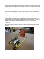
The hardware consists of a dual motor tracked chassis made by Dagu Electronics called the Rover 5. This kit
came with 2 DC motors with 87:1 gear ratios to provide extra torque and optional wheel encoders. Other kits
came with 4 motors, but the front 2 motors were disabled by removing one of the interconnecting gears in
the transmission. The optional encoders were omitted because this project did not require absolute speed
control. To maintain a fixed distance from the lead object, an ultrasonic distance sensor was used. The
XL−MaxSonar−AE4, made by MaxBotics, emits a 44 kHz tone and internally measures the time between the
transmission and the echo to determine the distance. Using this distance as the feedback mechanism to the
MCU, we are able to control the speed of the motors to maintain a fixed distance of 50 cm to our target. The
motor control consists of a motor driver chip by Freescale (MC33926) and the PWM function in the
Microchip PIC18F46K22 MCU. The MCU is the heart of the system. It ties together the sensor readings, motor
speed, back-up beeper, and hazard lights.
Power Circuits:
A single 9V battery is fed into an LM2940S-5.0 voltage regulator. It converts the 9 VDC to 5 VDC used to
power the MCU and peripherals.
A separate battery pack with six 1.2 VDC NiMH batteries connected in series provides up to 7.2 VDC to the
motor driver H-bridge FET switches to power the motors.
Having separate power sources insures that the power hungry and noisy motors do not interfere with the
logic systems and cause brownout conditions or intermittent behavior in the MCU.
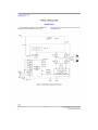
Schematics
Test Plan and Results
The objective in testing the Autonomous Trailer is to determine the success of both the hardware and
software design. Each functional component of the system will have a test assigned to it, and will be
evaluated based on an appropriate criteria. Some components cannot be adequately tested quantitatively
and will be given a qualitative assessment. After testing each component as independently as possible, the
system as a whole will be evaluated as far as it meets the design objectives.
1. Distance Sensor
2. Data Processing
3. System Operation and Motor Control
1. Distance Sensor
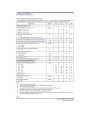
The distance sensor will be tested under three physical conditions: 20cm, 50cm and 100cm. 20cm indicates
the smallest value that the sensor can reliably read and 100cm represents a high value for what we’d expect
to measure. For our purposes, we also test the sensor at 50cm because that is our Trailer’s defined set point.
At each distance, with an obstruction appropriately placed, an analog and digital reading will be taken.
Analog measurement will be taken directly from the sensor output with a digital multimeter; while digital
measurements will be taken using the watch-window in the MPLAB development environment.
20cm:
Expected analog reading: 98mV (4.9mV/cm per datasheet)
Expected digital reading: 20
Observed analog reading: 108 mV
Observed digital reading: 0x16 or 22
50cm:
Expected analog reading: 245mV (4.9mV/cm per datasheet)
Expected digital reading: 50
Observed analog reading: 246mV
Observed digital reading:0x30 or 36
100cm:
Expected analog reading: 490mV (4.9mV/cm per datasheet)
Expected digital reading: 100
Observed analog reading: 491mV
Observed digital reading: 0x67 or 48
Conclusions:
The conclusions for the distance sensor are impressive. The inaccuracies of the voltmeter and the manually
measured distances may account for the differences between expected and observed results. We were also
impressed at how well our ADC translated the analog values to accurate digital ones. A future study might be
made of the accuracy of ultrasonic sensors versus other types of sensors (eg infrared).
2. Data Processing
This software section of the system translates information from the distance sensor to a useable value for
the motor control stage. It needs to compare the digital distance sensor values it receives to a pre-defined
set-point (for our purposes, 50cm), and adjust the motor output value to force the vehicle to better
approximate the set-point through its speed.
By simulating different distance situations, we can show the processing stages ability to adjust the speed of
the vehicle either up or down. Some of the situations are as follows. When the distance sensor is continually
out of range high, we want the processing stage to recognize this as an error, bring the vehicle to a stop and
put the hazards on. When the distance is high, but not out of range, we want the processing unit to output a
high incremented speed value. When the distance is low, we expect a lower incremented value. When the
distance is right on (50cm), we want to maintain the trailer’s current distance. Likewise we want to test that
the processing unit signals a deceleration when the distance is below the set-point. All of these tests can be
verified by using the watch window functionality of the MPLAB environment.
3. System Operation and Motor Control
For this section, we are interested in the system’s ability as a whole to serve the defined objective. That
objective is to maintain a defined following distance from a lead vehicle or simulated obstruction. This is a
qualitative test.
For the first test (the Collision Test), we run the Autonomous Trailer with a simulated lead vehicle in front of
it, maintaining the defined 50cm. When the lead vehicle comes to an abrupt stop, we want to verify that the
Autonomous Trailer quickly comes to a stop as well. Our group tested with more primitive design than is
currently under development (improvements were conceived based partly on these tests). In this case, the
PWM duty-cycle for the motors was basically made identical to the value of the distance sensor.
1. Collision Test:
After running smoothly at its max speed, our Autonomous Vehicle came to a stop 30cm before the fixed
obstruction.
Conclusion:
The reason for the 30cm stopping distance can be interpolated from our design. To be clear, this test was
not run with the 50cm set-point that we devised for later designs. For this test, the distance values directly
controlled the PWM duty-cycle. At 30cm the PWM duty-cycle was reduced to such a level that the motors
could not overcome the resistance of the tracks and the friction of the floor. We know 30cm is less than 50%
duty-cycle, and that appears to have been the threshold
It was surely a success for us that the vehicle did not crash into the obstruction. For our more sophisticated
design, we sought to achieve a more proportional control of the vehicle and maintain a fixed set-point
through incremental control. The added functionality of moving in reverse, hazard lights and a buzzer also
improved on this early design.
For the second test, we are interested in the ability of our control system and motors to respond to the
gradual changes of speed in the lead vehicle. We are interested in the ability of the Trailer to gradually
increase in speed, gradually decrease in speed and to switch to reverse.
2. Direction and Speed Test
For this test, we observe the vehicle traveling slowly to maintain a distance and then accelerating to catch up
with a speeding lead car. Clearly the vehicle’s max speed is often less than that of the moving obstruction.
This means that Autonomous Trailer is frequently operating at its peak speed.
One of the conditions we were concerned about was the vehicle’s oscillation around a set-point. Because of
the slow speed of the vehicle (10cm/s), overshooting the set-point appeared not to be a problem. Clearly the
lower % PWM duty-cycle values (as low as 50%) were inhibited by the resistance of the tracks. We may
incorporate this fact into future code.
A YouTube video of the vehicle in action has been uploaded to: http://www.youtube.com/watch?v=zsaG9soie4
Conclusions
The goal of this project was to prove the concept that you can follow a moving object with a microcontroller
and a distance sensor to maintain a set distance. The complexity was in creating the algorithm and associated
software. We each successfully built our own vehicles with all of the core features working.
To make this a more robust system, a bit more code polishing may be required. In the future, adding in an
encoder to measure and track the absolute speed could be implemented to improve on the design.
References
PIC ® Microcontroller: An Introduction to Software & Hardware Interfacing, Huang, ISBN 1-4018-3967-3
www.pololu.com
Appendixes
Time Tracking
Time was allocated evenly between all three group members.
Task
Steve Hopkins
Conor Cahill
Adam Morse
Percentage of allocated time
Total
Research and Planning
5%
3.75 hrs
Algorithm Development and
coding
70%
52.5 hrs
Simulation and Testing
20%
15 hrs
Documentation
5%
3.75 hrs
Total group hours
(25hr * 3 people)
75 hrs
User Manual
1. Safety Concerns
2. Setup
3. Using Your Autonomous Vehicle
4. Shutdown and Storage
5. Troubleshooting
6. System Components
Safety Concerns
Your new Autonomous Trailer is an easy-to-use, fun demonstration tool for simulating collision avoidance
systems. Yet with all electrical systems, there are important safety considerations to keep in mind.
•
•
•
•
Adult Supervision: the Autononmous Trailer should not be used without adult supervision
Pinch Points: exercise caution when handling the robot, as the tracks can begin moving unexpectedly
creating a pinch point between the wheels and the tracks
Unintended Additions: make no modifications to the existing system in particular do not power the
device by anything other than the supplied 9V battery
Shock Hazard: the Autonomous Trailer operates at low voltages yet it still important not to contact
exposed terminations and not to remove the 9V battery while the tracks are in motion
Setup
The Trailer is easy to set up straight out of the box. Its programming is done in advance and all the pieces
come pre-assembled. The following elements are all that is involved:
•
•
•
•
•
•
•
If you must operate the vehicle outside, only do so in a clean environment
Avoid operating the vehicle in the rain or in dusty/dirty conditions
Pick the vehicle up by the chassis and avoid touching PCB boards whenever possible
Ensure that the microcontroller demoboard always is firmly attached to the chassis assembly (via the
supplied rubber bands or other means)
Place the car on your knee (or similar block) for setup such that the treads do not make contact with
any surface
Adjust the ultrasonic distance sensor so that it is level to the ground and points directly ahead of the
vehicle
Tuck all stray wires into the cab of the vehicle so they do not make contact with the tracks
•
•
If a ‘lead car’ is to be used, place it a couple of feet in front of where the Autonomous Trailer will
begin its course
Remove all obstructions from the straight path along where the cars will travel
3. Using Your Autonomous Vehicle
•
•
•
•
•
Attach the 9V battery to the demoboard
Plug the ENABLE pin plugged into the demoboard at RC7
After the tracks have begun to turn, place the vehicle on the floor behind the object that is to follow
The Autonomous Trailer is designed to track 50cm behind the lead vehicle
It will adjust its speed, and move forward and backwards, based on the movement of the lead vehicle
4. Shutdown and Storage
•
•
•
•
•
To shut the device off, first lift it off the ground
Remove the ENABLE pin at RC7
Remove the 9V battery from the demoboard
Remove the tracks from the vehicle to lessen the strain on the wheels and gearbox
Store in a dry environment
5. Troubleshooting
•
•
If the vehicle does not follow the target while in its operating range (45 cm to 55cm):
o Adjust the distance sensor so that it points more directly at the object
o Modify the lead vehicle so that it can be better recognized by the trailer (tape a vertical piece
of cardboard on it, for instance)
o Ensure that the lead vehicle does not exceed the Autonomous Trailer max speed of 10cm per
second
o Ensure that the distance sensor wires are firmly plugged into the demoboard
o Confirm that wires are in the correct terminals (see Hardware Schematic)
If the vehicle struggles to move:
o Relocate to a surface with less friction
o Ensure the all terminations between the motor controller, battery pack and demoboard are
adequately connected
6. System Components
Distance Sensor
Microcontroller
Demoboard
9V Battery
location
Robot Chassis
I/O Terminal
Block
Motor
Control
Board
Datasheets
Rover 5
Rover 5 is a new breed of tracked robot chassis designed specifically for students and hobbyist. Unlike
conventional tracked chassis’s the clearance can be adjusted by rotating the gearboxes in 5-degree
increments. “Stretchy” rubber treads maintain tension as the clearance is raised.
Each gearbox has an 87:1 ratio includes an optical quadrature encoder that gives 1000 pulses over 3
revolutions of the output shaft. The chassis can be upgraded to include four motors and encoders making it
ideal for mecanum wheels.
Inside of the chassis are 4 noise suppression coils at the bottom and a battery holder that accepts 6x AA
batteries. It is recommended to use NiMh batteries as they last longer and have a higher current output than
Alkaline batteries.
Video of the chassis in action can be seen here:
Video indoors autonomous: http://v.youku.com/v_show/id_XMjE5NzkwODA0.html
Video outdoors RC mode: http://v.youku.com/v_show/id_XMjIwMTkxODk2.html
Dimensions:
Specifications:
Motor rated voltage: 7.2V
Motor stall current: 2.5A
Output shaft stall torque: 10Kg/cm
Gearbox ratio: 86.8:1
Encoder type: Quadrature
Encoder resolution: 1000 state changes per 3 wheel rotations
Speed: 1Km/hr
Motor Driver: Freescale MC33926
Ultrasonic Distance Sensor: MaxBotics XL-MaxSonar-AE4 (MB1340)
MCU: Microchip PIC18F46K22 (Partial)
Buzzer: Mallory AST1240MLTRQ