1
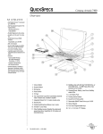
HydroPack
Submersible Battery Pack
USER’S MANUAL
Rev C
H
Hyyd
drroo--O
Op
pttiiccss,, B
Biioollooggyy &
& IIn
nssttrru
um
meen
nttaattiioon
n
L
Laabboorraattoorriieess
Lighting the Way in Aquatic Science
www.hobilabs.com
[email protected]
Revisions
Rev C November 2009, Update illustrations, add information about multiple
packs, update capacity table based on recent Energizer spec sheet.
Rev B October 2009, Changed pinout
Rev A July 2008, Reformatted
April 5, 2002: First Release
2
1.
INTRODUCTION
HydroPack is a submersible battery pack that uses commonly available D cells for
high-power or long-endurance oceanographic deployments. 20 cells are wired in two
groups of 10 cells each, providing a nominal output of 12 to 15V and capacity of up
to 30Ahr (see further notes in section 3.4). Diodes prevent harmful interactions between
the cell groups and also allow multiple HydroPacks to be safely paralleled (with
appropriate cables). Each cell group is protected with a 2.5A resettable fuse. In the event
of an overload or short circuit, the fuse will activate and reduce the current to a low level.
Once the fault condition is removed, the fuse will return to its normal state in a short
time.
The HydroPack case is made from type 316 stainless steel and acetal plastic to
prevent corrosion. It is also equipped with a pressure relief valve that limits internal
pressure build-up in case of a fault condition such as a water leak or gas generation by the
batteries.
2.
PRECAUTIONS
• Always inspect o-rings and grooves before deployment, and replace the
o-rings if in doubt about their condition.
• Use care to avoid short circuits when connecting multiple packs with Ycables (see Figure 4).
• Replace all cells at the same time with fresh cells of the same type.
• Remove batteries before shipping the packs or storing them.
3
3.
OPERATION
3.1.
Connecting
The HydroPack uses an Impulse or SubConn MCBH2F connector. Mate to this
using an MCIL2M inline connector. Pin 2 is positive, and pin 1 is the return. NOTE:
This pinout has changed from earlier HydroPacks. Units delivered up to October,
2009 had opposite polarities.
3.2.
Removing Batteries
Remove the endcap by inserting a 3/16” hex wrench into the bolt head in the
center of the end cap (the off-center bolt is the pressure relief valve), and turning it
counter clockwise until the end cap is free.
To remove the old batteries you can simply tip the HydroPack to dump them out.
If this is not practical, you can instead remove the top layer of batteries, one at a time,
then grasp two of the outer rods and lift
the rod assembly up to remove the lower
layers as shown in Figure 1 (only Series
150 or later HydroPacks have removable
rod assemblies).
3.3.
End Cap Inspection and
Maintenance
Figure 1. Using rod assembly to lift batteries
from pack (Series 150 HydroPacks only)
Whenever you remove the end
cap, inspect the o-rings and the inner surface of the case where the o-rings seal, to be sure
they are free of damage and contamination. If the o-rings may have become dirty during
handling, remove them from their grooves and clean both them and the grooves. Do not
use any hard, sharp or abrasive objects on the o-rings or their grooves.
The o-rings should be slightly slippery. If not, apply a very light coating of an
appropriate lubricant such as Dow Corning 55 or Parker O-Lube.
4
If the threads of the end cap’s retaining screw do not run smoothly when you
remove and replace the end cap, apply a small quantity of anti-seize lubricant or silicone
grease to them.
Check that the pressure relief valve (the off-center bolt in the end cap) is seated
properly and does not protrude.
3.4.
Preparing for Deployment
In Series 150 or later packs, be sure the removable
post assembly is resting flat on the bottom of the pack
before inserting batteries. Insert new batteries with their
positive (button) side facing the open end of the tube, as in
Figure 2. It is safe to let the batteries slide down into the
pack if it is standing vertically. Always replace the entire
set of batteries at once.
Figure 2. Cell orientation
Mixing batteries of different
types, or different states of charge, can lead to battery leakage and failure.
Position the end cap over the open end of the case, with the large springs centered
on the battery tops and the small springs on posts positioned to contact the posts between
the batteries (see Figure 3). Without rotating the cap, place it on the end of the case.
While holding the cap to prevent it
from rotating, tighten the center bolt with
the 3/16” hex wrench.
Tighten the bolt
enough to ensure that the lid is resting
firmly on the tube, with no gap between the
end cap flange and the tube, but do not
apply more than moderate hand torque.
3.5.
Energy Capacity
The actual energy capacity of
Figure 3. Correct end cap position for
installation
alkaline batteries varies greatly depending
on how heavily they are loaded, whether
5
the load is continuous or intermittent, the temperature at which they are discharged, and
the minimum voltage suitable for the load. It is difficult to accurately model all these
effects, so one should always estimate conservatively, and if possible run tests under
realistic conditions.
The highest capacity alkaline D-cells currently available claim capacities of
18 Ahr, based on very favorable test conditions: room temperature, a light load of 25mA,
and an ending voltage of 0.8V per cell. Because the HydroPack contains 2 paralleled
groups of 10 cells, this corresponds to totals of 36 Ahr and about 7.5V (0.8V x 10 cells
minus one diode voltage drop). However the actual capacity will be significantly lower
Load Capacity
(mA)
(Ahr)
20
30
100
28
200
22
400
20
600
18
800
14
1000
10
with heavier loads or lower temperatures.
The table at left uses figures derived from the data sheet
for Energizer type EN95 D cells. They are based on an ending
voltage of 1.05 V/cell (10V output from the HydroPack), and
continuous discharge at 21 C. The capacity can be expected to
drop at lower temperatures, to about one-half of these values at
5 C.
For a given current load, especially for higher loads, intermittent use can provide
significantly higher total capacity than continuous use. For example, at a current load of
1 A, reducing the duty cycle to 2 minutes per hour provides roughly 50% more total
charge than continuous use. The discrepancy between intermittent and continuous use
decreases at lower loads; at 50 mA or less there is no significant difference.
3.6.
Using Multiple Packs
Multiple HydroPacks can safely be wired together to increase their total capacity
for heavy loads or longer durations. Because each HydroPack contains diodes to prevent
reverse current flow, simple Y-cables can be used to connect them in parallel.
WARNING: When plugging two packs together with a Y-cable (see Figure 4), once the
first pack has been connected, its voltage is present on the male connector for the second
pack, and vulnerable to short circuits. To avoid this, ALWAYS plug or unplug the
second leg of the Y immediately after the first.
6
Figure 4. Beware: when one leg of the Y is plugged into a pack, the second plug is live.
7
4.
SPECIFICATIONS
•
Diameter: 9 cm (3.5”)
•
Length: 37 cm (14.5”), not including connector
•
Materials: 316 stainless steel and acetal copolymer
•
Weight, with batteries: 5.3 kg dry, 2.5 kg submerged
•
Cell capacity: 20 D cells
•
Depth rating: see the warranty sheet supplied with your HydroPack or the
label on Series 150 or later units.
•
Battery configuration: 2 series strings of 10 cells, each with a high-efficiency
diode to prevent reverse current, and a 2.5A self-resetting fuse to protect
against overload.
•
Output voltage: 16V max (with fresh alkaline cells)
•
Connector: MCBH2F, 2-pin female.
o NOTE: These pin assignments were different for units delivered
up to October, 2009
o Pin 1 = return
o Pin 2 = positive voltage
•
5.
O-rings: 2-151 (inner), 2-235 (outer)
CUSTOMER SERVICE
If your equipment needs to be returned to HOBI Labs for repair, maintenance or
calibration, contact HOBI Labs customer service ([email protected]), or fill out an
RMA request form at www.hobilabs.com.
For technical support or questions about your instrument, contact our technical
support department at [email protected].
8