1
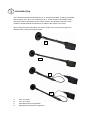
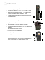
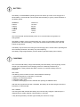
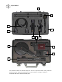
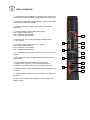
Shearwater ECM
LOCATORXD
User manual
SECTION ONE
INTRODUCTION
SECTION TWO
EQUIPMENT
SECTION THREE
CONFIGURATION
SECTION FOUR
CONTROL MODULE
SECTION FIVE
DISPLAY MODULE
SECTION SIX
BATTERY
SECTION SEVEN
CHARGING
SECTION EIGHT
ASSEMBLY
SECTION NINE
TEST
SECTION TEN
PRINCIPLE
SECTION ELEVEN
SEARCHING
SECTION TWELVE
DISCOVERY
SECTION THIRTEEN
OPERATIONAL NOTES
SECTION FOURTEEN
PHYSICAL DATA
SECTION FIFTEEN
TECHNICAL DATA
SECTION SIXTEEN
HYGIENE
1
INTRODUCTION
The LOCATOR range of Non Linear Junction Detectors (NLJDs) were introduced in the mid
1980s for the detection of hidden electronic circuits. The LOCATOR has undergone many
development changes since it first appeared on the market.
The LOCATOR XD incorporates the very latest technology in Non-linear Junction Detector
evaluation. Designed for the detection, location and analysis of concealed passive or active
electronic devices. Small, lightweight and robust for the harshest of environments. The
LOCATOR XD is an essential tool for electronic countermeasure searches, explosive
ordinance disposal and a variety of security applications.
The LOCATOR XD has been designed to the very highest standards, in terms of functionality,
ease of operation and reliability. As a result the LOCATOR XD offers a performance that is
second to none in quality, cost and operation.
1. CONTROL MODULE
LOC-XD-001
2. DISPLAY MODULE
LOC-XD-002
3. ANTENNA HEAD
LOC-XD-003
4. 11 0/240V CHARGER
LOC-XD-004
5. CHARGER LEAD
LOC-XD-005
6. BATTERY PACK (2)
LOC-XD-006
7. SEPARATION LEAD
LOC-XD-007
8. EXTENSION TUBE
LOC-XD-008
9. EARPHONE
LOC-XD-009
10.TEST TARGET
LOC-XD-010
11.TRANSIT CASE
LOC-XD-011
EQUIPMENT
8
5
9
11
7
6
1
6
3
10
4
2
The TRANSIT CASE has a double safety lock. There is a pressure release valve positioned
below the handle. Should the equipment have been subject to change in altitude or
temperature the valve will automatically open.
CONFIGURATION
The LOCATOR XD has been designed to be as versatile as possible, providing the operator
with the option of an ‘All in one’ single body unit or, as with previous LOCATOR models,
having the antenna separated from the control module. The equipment has been made
modular to enable alternative antennas to be added to the system in the future.
When using the antenna separately, the control module can be held by using either the
shoulder strap or body belt fixings provided.
A
B
C
D
A.
B.
C.
D.
‘All in one’ basic configuration.
‘All in one’ extended configuration.
Separated antenna configuration.
Separated and extended configuration.
CONTROL MODULE
1.
Increases VOLUME level. (20 steps from min. to max.) Volume can be
increased quickly by holding down the button.
2.
Decreases VOLUME level. (At minimum level the speaker is muted).
3.
Selects one of four transmitter frequencies, A, B, C or D. (In case of
interference from Standing Waves see Section 9, part 2).
4.
1
2
3
4
Hold down button for 3 seconds to turn ON/OFF (this protects against
inadvertent operation).
5.
Green LED indicates that the control module is ON.
6.
Red LED indicates a TRUE target is being detected.
7.
Ear-piece connection point - when in use it disconnects the internal
speaker.
5
6
8
8.
An internal speaker is fitted to the right side of the module.
9.
A shoulder strap can be fixed to the pouch when using with the antenna
separated.
Belt attachment points are also available.
9
7
10. Connector for Data and Co-axial outputs.
11. Battery securing strap.
12. Battery aperture.
The controls for the most commonly used functions such as receiver
selection and range control, have been placed conveniently below the
display screen. Selection via a unique 4-way thumb control.
10
11
12
DISPLAY MODULE
1. Indicates the type of TARGET by comparing the second and
third harmonic signal strengths, TRUE (red) and FALSE (green).
2. Indicates the level of the TX (transmitter) output power, which
determines the detection RANGE.
3. Indicates BATTERY LEVEL. See section 6 for de1ailed
description.
4. Indicates AUDIO output to RX2 (false target)
GR = Geiger click/rising tone.
FM = Frequency demodulation.
AM = Amplitude demodulation.
1
5. Indicates one of four preset operating FREQUENCIES
(A, B. C and D).
2
6. Indicates AUDIO output to RX1 (true target)
GR = Geiger click/rising tone.
FM = Frequency demodulation.
AM = Amplitude demodulation.
5
4
7. R1 - Received signal strength indication of first receiver (true
target).
8. R2 - Received signal strength indication of second receiver
(false target).
9. Increases the detection RANGE by increasing the
TX output power (30 steps - min to max). Range can be
increased or decreased rapidly by holding down the button.
10. Selects AUDIO output of RX2 (false target) to the speaker or
ear-piece.
11. Selects AUDIO output of RX1 (true target) to the speaker or
ear-piece.
12. Decreases the detection RANGE by decreasing the TX
output power.
3
6
8
7
9
10
11
12
BATTERY
The battery is a Nickel Metal Hydride type that can deliver up to 40% more energy than a
NiCad battery. LOCATOR XD communicates with the battery to give a precise indication of
the battery status.
SEGMENT
6 Green
5 Green
4 Yellow
3 Yellow
2 Red
1 Red
CAPACITY
75-100%
50-75%
30-50%
20-30%
10-20%
0-10%
The LOCATOR XD will automatically switch off 10 seconds after all segments are
extinguished.
The battery condition can be checked before use, via the on board battery level indicator
(located on the side of the battery). Just press the outlined button and the four LEDs will
indicate charge status.
The battery may become warm during use and charging, this is normal. When operating time
has noticeably shortened, the battery may need replacing.
The battery will give approximately 2 hours duration (standard output power version)
CHARGING
The LOCATOR XD battery charger automatically tests the battery at the beginning of each
charge cycle. Supervision of the charging process is constantly monitored by a
microprocessor. Safety features like delta V switch off, as well as a safety timer are
integrated.
LED - RED
The flashing of the red LED can have several different meanings:
1. Initial test programme in operation (10 seconds).
2. Battery not connected property.
3. Defective battery pack.
4. Indicates discharging has been selected after pushing the PRESS button.
After the test programme has been completed, the battery will be bulk charged, this will be
indicated by a solid red LED.
LED - GREEN
The solid green LED indicates the battery has now been fully charged. It will be kept in a
charged state by trickle charging until the battery is removed.
A fully discharged battery will take approximately 90 minutes to charge.
ASSEMBLY
Assembly of the basic system.
1. Connect the DISPLAY MODULE to the CONTROL MODULE by aligning the plug and
socket.
lock by twisting the securing collar.
2. Connect the ANTENNA HEAD to the DISPLAY MODULE by aligning the plug and socket,
lock by twisting the securing collar.
3. Insert a charged BATTERY PACK into the CONTROL MODULE.
Make sure that the "D" shape on the battery lines up with the "D" shape of the aperture in the
control module. Push the battery in until positive connection is made and then fix securing
strap.
4. No other tuning or preparatory work is required and the system is ready for use, subject to
battery condition.
5. DO NOT TURN ON THE SYSTEM WITHOUT THE ANTENNA HEAD CONNECTED.
ANTENNA HEAD
DISPLAY MODULE
BATTERY PACK
CONTROL MODULE
TEST
With a fully charged battery and assembly completed as outlined in section 8, the test routine
can begin.
1. Switch ON by holding the ON/OFF button on the CONTROL MODULE for 3 seconds and
the DISPLAY panel will illuminate. To Turn OFF the LOCATOR XD again hold the button
down for 3 seconds (this is to protect against inadvertent operation).
Please Note: When the Locator XD is turned OFF the control settings are updated and
memorised. This enables the operator to resume searching quickly after a battery change.
Only the TX (range) level will revert to a factory set default setting (1) for safety reasons.
2. The operator should now check for any STANDING WAVE signals that may interfere with
the operation of the system. This can be easily achieved (with the antenna positioned away
from any possible target) by turning the RANGE level to ZERO and by looking at the SIGNAL
strength indication of R1 and R2 on the DISPLAY MODULE. If there are NO signal levels
displayed, this confirms that there is no interference and the operator can continue as normal.
If there are signal levels on either R1 or R2 displays the operator will have to select an
alternative channel by using the FREQ SEL (frequency select) button. Select the next usable
channel and check again for interfering signals.
3. Set the RANGE (TX level) to levelS.
4. Select GR (geiger) mode for the RX1 (True target).
5. Place the TEST TARGET on a table or similar (not a metal surface).
6. Test the system by holding the ANTENNA HEAD approximately 20 cm away from the
TEST TARGET. A positive response, being an audible rising tone and a visible increase in
signal strength.
In practice the operator will find that a TEST TARGET becomes un-necessary as there are
normally targets such as telephones and other equipment that provide satisfactory evidence
of operation.
7. Adjust the VOLUME to a preferred level when using the TEST TARGET.
8. The LOCATOR XD is now ready to use. For further operational detail please refer to
section 11 - SEARCHING.
PRINCIPLE
The LOCATOR XD combines extremely efficient radio transmission with reception of great
sensitivity, which entails contemporaneous despatch and analysis of signals at different,
precisely determined frequencies. The intention is to trigger a reaction in targeted
semiconductors.
Semiconductors, transistors and diodes have the characteristic of responding to suitably
defined radio waves and re-radiating at certain calculable frequencies. It therefore follows that
if one can provide a signal and analyse any response, it is possible to indicate and appraise
such items, known generally as non-linear junctions.
As all modern electronic circuitry contain semiconductors, the logic of searching by the
technique is inescapable and it proves to be a most successful routine, provided that the
equipment is well designed and manufactured to the very highest standard.
It is important to recognise that neither the distance whence a reaction occurs nor its strength
is any indication of the relevance or size of a discovered target; any response must be
evaluated thoroughly. Once a TRUE target response is indicated it follows that other
examination and assessment be brought into play.
The fundamental or original signal generated by the unit's transmitter may be re-radiated by
the target on the second (i.e. twice the fundamental) and this response is picked up by the
first receiver, which is set to that specific frequency. Similarly on the third with the second
receiver. Theory says a false target will display a higher signal level on the third harmonic R2,
whereas a true target, will show a stronger signal on the second harmonic R1.
The transmission is intentionally not modulated, but the re-radiated one may, either by
amplitude or frequency, be dependent on the nature of its operation (if active). Accordingly,
LOCA - TOR XD 'reads' the received signal whether it is un-modulated, FM or AM, which the
mode selection permits.
A naturally occurring non-linear junction can give a response which mimics that sought from a
synthetic or manufactured one. However, such a reaction is generally disproportionate at the
second and third harmonic levels.
LOCATOR XD has the benefit of a second receiver tuned to the third harmonic
(three times the fundamental) to enhance this analysis of the return signals with automatic
comparison displayed to assist.
LOCATOR XD automatically compares these signals and indicates whether the response is
FALSE (green for benign target), or TRUE (red for a real target).
SEARCHING
1. With a fully charged battery and the test procedure outlined in section 9 completed, the
detection routine can begin.
2. Switch the unit ON by depressing the ON/OFF button on the control module for 3 seconds.
3. The operator should remove or avoid interfering items that may be picked up by the LOCATOR XD, including his own communications and any test targets etc from the area being
searched
.
4. Adjust the ANTENNA HEAD by moving it from its stored position (parallel with the handle)
to the one that is at right angles with the handle. Movement of the head is restrained by a
friction hinge, which can be tightened if necessary.
5. Aim the flat foam face of the ANTENNA HEAD towards the search area. The search zone
is indicated by the antenna's footprint. The outgoing signal being projected away from the
face of the ANTENNA HEAD in a cone shaped beam of approximately 30 degrees.
The antenna is circularly polarised and offers effective omni-directionality. Therefore
eliminating the risk of missing targets due to incorrect antenna polarisation.
6. Adjust the RANGE control to maximum, select GR mode on RX1 (red) on the display
mode, ready to detect any TRUE targets.
When no relevant target is being picked up the audio tone will be a constant monotone click,
as the target is approached this will increase in speed and rise in frequency to a high pitched
continuous reaction.
7. When a response is obtained turn down the RANGE, this will reduce the area of search
and the desired device may be located with precision.
Range control is achieved by variation of the transmitter power whereas the receivers remain
constantly highly sensitive. The audio and visual outputs are driven by direct reference to the
nature and the strength of the incoming signals.
DISCOVERY
The process indicates the discovery of a TRUE target and careful use of the range control
helps to locate its position.
As the nature and the layout of the discovered device is unknown the exact pattern of the reradiated signal cannot be forecast, but it is unlikely that the precise location will be far from
that inferred by the antenna's footprint.
An actual physical examination of the area may be carried out, during which the device can
be identified, its nature assessed and any threat it may pose may be considered.
Continuing with the search procedure one may evaluate the target by varying the receiver and
mode selected. Should the item be a FALSE target the Harmonic TARGET comparison will
show increasingly green.
Varying the receivers and modes will enable the operator to assess the target for activity and
some evidence of the nature of the discovered item. By selecting RX1-AM mode a beat, hum
or even audio may be heard. If the target is genuine, but passive, it will still create a reaction
that indicates a TRUE target.
If a FALSE target is found, it can be easily confirmed by selecting the RX2-AM mode and
listening to the audio output. By knocking in the vicinity of the targeted area, a FALSE target
will produce a crackling sound that will be very unstable. Whereas a TRUE target in RX1-AM
mode will be completely silent and stable.
As both receivers will be obtaining an incoming signal, there can be both red and green in
greater or lesser proportions showing at the same time. However the more green, the more
likely it is that the target is FALSE/benign.
Other security procedures must be applied, if the identified items remains suspect or,
perhaps, incapable of further appraisal (as when it is contained in a suitcase or in furniture)
without further countermeasure or detection techniques. Standard operating procedures are
not part of this guide.
Most operators will have metal detectors, radio transmitter discovery equipment and similar to
assist them, but the value of LOCATOR XD is that it can silently locate powered or
unpowered circuitry and thus discover passive inoperative and active devices.
Common sense, operational knowledge and skills, plus additional equipment are always
needed to make full use of LOCATOR XD and establish a successful pattern to the required
defensive search process.
OPERATIONAL NOTES
It is evident that LOCATOR XD does not claim, alone, to identify illicit devices. Operator
counter surveillance skill and other related skills are essential to success and proficiency.
Apart from occasions when the located response comes from an otherwise problematical
source e.g. walling which does not permit dismantling or assessment from other directions,
the most probable practical difficulties arise from standing waves or false targets.
A standing wave, which effectively floods the reception, thus giving an apparently valid
response, would not be common. In such circumstances the selection of a different operating
frequency, as detailed in Section 9.2, will overcome this problem.
In the nature of things it is possible for a natural non linear junction to re-radiate in the manner
of a real true target, in what is often called "the rusty nail syndrome". The design of
LOCATOR XD makes it as immune as practical to such false targets and comparison of the
harmonics helps discriminate between them.
Natural non linear junctions are generally due to corrosion between metal and related
substances. They can often be inhibited by breaking the contact between the materials with
vibration or movement (typically a knock on the surroundings with a soft headed hammer will
do the trick) during which the response will vary or "crackle".
Targets that are screened by metal can prevent or diminish signals; accordingly cupboards
and containers should be examined open since the emissions may not penetrate. Heavily
tarnished or corroded metal could also cause a false reaction.
Should a target item be surrounded by metal (in the form of a faraday cage) it is unlikely to act
as a competent radio device. Although, it would still require an external aerial to transmit its
signal and this should allow it to be picked up by LOCATOR XD.
The convenience and sensitivity of the LOCATOR XD minimises misleading indication though
false readings that will alert the operator and bring his expertise into use. An experienced
operator and LOCATOR XD together will usually mark and assess any threatening
responses.
Please contact your supplier for further information and training.
PHYSICAL DATA
TRANSIT CASE
Black, moulded in structural resin, foam inserts.
Dimensions 48 cm by 34 cm by 12 cm. Weight 2.24 kg.
CONTROL MODULE
Black, machined aluminium case and protective pouch.
Dimensions 21 cm by 11 cm by 4 cm. Weight 0.98 kg.
DISPLAY MODULE
Black, aluminium tube, plastic display fascia, foam grip.
Dimensions 35 cm by 3.6 cm diameter. Weight 0.36 kg.
ANTENNA HEAD
Black, fibreglass and abs, aluminium bracket.
Dimensions 17 cm diameter by 4 cm. Weight 0.40 kg.
EXTENSION TUBE
Black, aluminium tube, foam grip.
Dimensions 36 cm by 2.5 cm diameter. Weight 0.18 kg.
SEPARATION LEAD
Black, coax lead with protection braid covering.
Dimensions 120 cm. Weight 0.32 kg.
110/240 CHARGER
Black, plastic housing complete with lead and plug.
Dimensions 14 cm by 7.5 cm by 6 cm. Weight 0.48 kg.
EARPHONE
Black, lightweight, plastic, rubberised ear grip.
Dimension 6 cm by 4 cm by 4 cm. Weight 0.02 kg.
BATTERY PACK (2)
Black, Nickel Metal Hydride battery, plastic.
Dimensions 15 cm by 5 cm by 1.5 cm. Weight 0.32 kg.
COMPLETE SYSTEM
Total Weight of all items above in transit case. Weight 5.6 kg.
TECHNICAL DATA
TRANSMITTER
Frequency range
Power output
Filtering
Output connector
RECEIVER (RX1)
Frequency range
Sensitivity
Input connector
RECEIVER (RX2)
Frequency range
Sensitivity
Filtering
Input connector
Four spot frequencies in the range of 869 - 916 MHz.
(dependant on country of use).
Adjustable 2mW to 500mW ERP (1W, 2 W optional).
10 section filter.
50 ohm double screened coax socket.
1738 - 1832 MHz (Transmitter selection controls receiver
frequencies).
Detection at -130 dBm. Filtering 6 section filter.
50 ohm double screened coax socket.
2607 - 2748 MHz (Transmitter selection controls receiver
frequencies
Detection at -130 dBm.
6 section filter.
50 ohm double screened coax socket.
DISPLAYS
Target response/comparison.
Transmitter output power.
Battery level, Mode selection (RX1 and RX2).
Frequency selection, signal strength (R1 and R2).
CONTROLS
4 way thumb control selects Range and Receiver selection.
Volume up and down, Frequency select and ON/OFF.
ANTENNA
Frequency coverage
Gain
Polarisation
860 - 920 MHz, 1720 - 1840 MHz and 2580 – 2760 MHz.
6 dbi.
RHC Right hand circular.
CHARGER
Input voltage
Charging current
Charge time
Type
100 - 240 VAC.
1200mNauto trickle charge.
Up to 1.5 hours.
Microprocessor controlled, short circuit and timer.
BATTERY
Type
Voltage
Test
Run time
Nickel metal hydride - smart battery.
10.8V DC/1700 mAh.
Built in battery level indicator.
2 hours - normal operation.
HYGIENE
LOCATOR XD is maintenance free and must not be opened without workshop knowledge
and supplier advice, otherwise any warranty will be deemed invalid.
The operator is requested not to alter any component or module, as without accurate
measurement equipment the critical set up of the instrument's power and sensitivity will be
altered detrimentally.
Ensure that all plugs and connections are kept free of dirt and foreign matter.
Keep your charger in a dry place. The charger should be disconnected from the mains when
not in use.
Batteries can explode, leak or catch on fire if exposed to high temperature. Do not open or
dismantle. Rechargeable batteries are not to be disposed of as domestic waste. Surrender
used batteries to your dealer or a battery collecting point.
NOTES