1
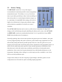
Sonnox Oxford Limiter
Operation Manual
Version 1.2 15th May 2013
1
1.
Introduction
The Oxford Limiter plug-in has been developed from decades of professional audio
experience to provide a very high degree of quality and capability in programme loudness
control and limiting functions. By employing highly accurate logarithmic sidechain
processing, along with innovative adaptive timing functionality using look-ahead signal
acquisition, the limiter provides exemplary performance, whether one is seeking general
transparent level control, programme loudness maximisation or heavily applied artistic audio
effects.
Unique processing in the form of the Enhance function provides the sample value limiting
needed to reliably avoid overloads in digital workstation environments, and allows
unprecedented volume and punch to be applied to programme beyond that available from
conventional limiting functions.
Comprehensive metering is provided, which displays not only conventional peak sample
value, but additionally allows the user to monitor the true validity of the programme in order
to avoid the generation of damaging reconstruction overloads in the target equipment, which
are often invisible during production (sometimes termed ‘inter sample peaks’).
A further function allows the user to dynamically correct for reconstruction overloads in real
time, thereby achieving maximum possible modulation levels without the risks of producing
‘illegal’ signals often associated with compression and limiting.
Comprehensive dithering functionality is included, with selectable and variable depth noise
shaping, which ensures first class mastering output quality in either 24-bit or 16-bit modes.
2
2.
Operation
2.1
Overview
The limiter plug-in is comprised of four processes, cascaded in the following order:
•
Pre-processing gain control
•
Programme enhancement and overshoot control
•
Reconstruction metering and compensation
•
Dithering and noise shaping
The primary purpose of the plug-in is to control peak levels and increase the volume, density
and presence of musical programme without an excessive loss of transient and dynamic
information that normally results from conventional peak limiting applications.
In order to achieve this, the application employs gain scaling and compression in the PreProcess section, and peak overshoot control in the enhancement section. These processes are
used in conjunction to enable the sound of transient and dynamic information within your
programme material to reach the output of the plug-in, despite very tight control of maximum
peak sample values.
The normal Enhance control setting for this action to fully occur is 100% and above in
Normal Mode, (or any enhance setting with Safe Mode selected). A variable control is
provided to allow the enhance process to be adjusted or removed completely (i.e. at 0%
setting), in which case the Pre-Process section may be used as a conventional programme
levelling application if desired.
A Safe Mode is provided which uses the enhance processing to permanently control peak
levels. In this mode the Enhance control varies the perceived loudness boost of the
programme by modifying the processing law.
3
2.2
Pre-Process Section
The Pre-Process section provides a musical programme
levelling function. Its primary purpose is to control
programme level over a wide range, in order to provide
optimum conditions for the following enhancement stage.
When the ENHANCE control is disabled in Normal
Mode (at 0% with SAFE MODE deselected), the PreProcess section can be used as a conventional levelling
section in its own right.
For clarity of operation, the plug-in gain structure is
arranged with the threshold permanently set to 0dB, referenced to normal input level.
Dynamic gain reduction is achieved by increasing the INPUT GAIN sufficiently for the
internal signal to surpass the 0dBr reference level. A total of 18dB gain boost is available for
this purpose, and the orange section of the INPUT meter illustrates the level range within
which gain reduction occurs when the plug-in is active. The final output modulation level is
set by the OUTPUT LEVEL control, which can be adjusted to compensate for dynamic
conditions produced by the programme and limiter settings, or produce a lower level
mastered output if required.
Programme gain is accurately controlled by look-ahead detection (to allow action before any
peaks are encountered) coupled with a logarithmic sidechain employing multiple
interdependent timing functions. Timing controls are provided to modify its action depending
on the programme type and production style. In order to reduce excessive short-term gain
modulation, a selectable AUTO GAIN function is included, which compensates for wider
input level variations by imposing a longer-term time constant that underlies the peak timing.
A variable progressive SOFT KNEE function provides varying degrees of soft limiting (for
lower settings), right up to large-scale gain management active over the final 10dB of
programme dynamic range.
4
2.3
Enhancement Section
The purpose of the enhancement process is to provide
sample value limiting and overall programme loudness
improvement. The process follows the Pre-Process section
in the signal path, and is controlled by a separate
ENHANCE fader from 0% (no action) to 125% (maximum
action). In Normal Mode, the range from 0% to 100%
fades in the effect to full level, at which complete sample
value limiting occurs. Settings from 100% to 125% further
modify the process to progressively increase loudness and
programme density at the expense of increasing potential
distortion artefacts.
SAFE MODE (see Pre-Process Section) is provided to allow absolute peak level control
without excessive enhancer action, even when using slow attack settings. In Safe Mode the
enhance process is set to run permanently, and the enhance fader modifies the action of the
process (rather than the proportion of the effect). Setting ranges from 0% to 100% control the
degree of programme loudness boost generated by the enhancer. The control region from
100% to 125% works identically to Normal Mode. It should be noted that in Safe Mode
signals at all levels are being processed permanently, therefore some minor changes to the
programme dynamics can occur even for a minimum setting of 0%.
The enhance process improves the perceived loudness and presence of the programme
material by modifying the dynamic and harmonic content of the signal. Since the method
used is different from the Pre-Processing section, it can further enhance the perceived volume
of a previously processed signal, while suppressing all signal overloads. As the limiting
action does not involve conventional sample value clipping, harsh distortions are avoided,
and programme detail and dynamic information is largely retained.
5
Also, since the plug-in has internal headroom, transient levels greater than notional maximum
modulation can pass from the limiter section into the enhancement stage. This means that
percussive overshoots, that would normally be lost in a conventional limiter (or would give
rise to overloads), may be included within the sonic results of the plug-in, producing both
richer dynamic sonic detail and a useful reduction in the perceived artefacts of the limiting
process, all without giving rise to any sample value overload.
This property enables slower attack times to be used in the Pre-Process section, without
creating output overloads, which would otherwise result in a need to reduce output levels.
The enhancement section can be used effectively on its own to produce programme
enrichment and peak value limiting, by using minimal gain reduction and slow timing
settings in the Pre-Process section. Or it can be used to enhance highly processed content
from the Pre-Process section to achieve even greater perceived loudness.
Because the enhancement process adds harmonic distortion during dynamics within the
programme, under some conditions side effects may occur depending on the content of the
programme material. Generally speaking side effects should be minimal when in Safe Mode
and for boost settings up to 100% when mastering in the presence of most commonly
occurring complex and dense composite material. However, some extra care may be needed
in the case of single solo instrument tracks where there may be a predominance of sustained
lower and middle frequency content. Settings above 100% are most useful when the
programme type is intended to be very loud, or where extra distortion may actually prove
advantageous within the style of the production.
6
2.4
Attack Timing
The addition of an ATTACK timing control is a
significant departure from conventional limiter
applications, and requires some explanation for the best
results.
Because the level detection within the plug-in looks ahead
of the gain control, peaks in the programme material are
acted upon in advance of the gain reduction process.
Therefore, at the fastest setting of the attack control,
programme peaks are controlled within a very small
margin (less than +0.25dB, with respect to continuous sine input conditions).
The ATTACK fader provides a means of increasing the attack time to achieve a favourable
improvement in the sonic qualities of the peak reduction process, by allowing peak
programme transient events to escape hard gain reduction. Since the plug-in has internal
headroom, these overshoot peaks are retained and are not clipped.
Peak overshoots resulting from a combination of the programme material and the action of
the Pre-Process stage are then passed to the enhancement section where their sonic signatures
can be added to the final programme sound. Providing SAFE MODE is selected, or the
ENHANCE fader is set to 100% or more in Normal Mode, no output sample value overloads
will occur from the plug-in, regardless of ATTACK or RELEASE time settings.
A combination of slower attack times and the enhancement process is therefore a very
powerful way to include transients in the output programme that would normally be removed
by conventional limiting processes. It can create a sonic quality and impression of dynamic
range that belies the degree to which the programme is actually being limited.
As an example of the difference this can make, if slower attack settings are used without the
enhancer, and the output gain is reduced to accommodate the overshoots (avoiding
overloads), using the same attack settings with the enhancer can provide up to (and beyond) a
3dB increase in average level, being able to legally increase the output gain setting and
around another 2dB of perceived loudness due to the enhance action itself. This can result in
a perceived loudness increase of 5dB to 6dB!
7
In general, very fast attack times will more readily remove extremely fine detail and shortterm events, but will produce greater harmonic disturbance.
Slower attack times will progressively allow finer detail to escape the harsh sound of fast
limiting, and longer term events will tend to assume a more rounded peak profile. Such
settings are usually kinder to the musical programme.
Please note that the only way slower attack settings can be used without a potential need for
a significant reduction of the output level control is when the ENHANCE control is set at, or
above, 100% or with SAFE MODE selected. These methods will ‘soft clip’ transients, ie.
compress their level before the onset of clipping, providing a warmer, valve-like saturated
sound. Alternatively, enable 16-bit or 24-bit dither, which will ‘hard clip’ over-unity
transients, ie. squaring the top/bottom of waveforms and resulting in a more distorted sound,
often found in transistorised circuits.
2.4.1
Using Pre-process without the Enhance Section
You should be aware that, since the Pre-Process section is a programme gain controller rather
than a simple sample clipper, programme peaks can cause a small increase in maximum
output sample value, even at the fastest attack time settings. If SAFE MODE isn’t selected,
or the ENHANCE fader is not set at, or above, 100% in Normal Mode, these peaks will
appear at the output of the plug-in. Increasing the attack times will further increase peak
overshoots, so if tight level control is required without the enhancer, it is best to leave the
attack at minimum setting.
Since the plug-in has internal level headroom, the output level control can be safely used to
compensate for any artistically intended overshoot without fear of causing internal signal
clipping.
8
2.5
Release Timing
The RELEASE control has a very wide range to
accommodate the maximum possible extent of programme
and production style. The ability to set very fast release
times is provided specifically to allow for the modelling of
short-term peaks over restricted gain reduction ranges, up
to a maximum of around 4dB. Such settings will result in
high levels of distortion for larger gain reduction ranges,
and are therefore unsuitable for overall level control
situations.
The AUTO GAIN function can be used very effectively to compensate for large level
changes, while still allowing fast peak modelling for shorter peak events, as the ATTACK
and RELEASE controls are permanently functional. So it is a good idea to keep AUTO
GAIN selected under most circumstances.
Generally speaking, faster release times produce the greatest perceived loudness, since gain
recovery happens quickly after peak events have passed, and average programme levels are
affected only during the shortest possible periods. However, since the gain recovery can
begin to occur between the waveform peaks of lower frequencies in the programme, there is a
trade off to be made between the speed of release and the generation of distortion. Such
distortion may be desirable under many conditions, particularly in loud popular music
productions, where some low frequency harmonics may add warmth and presence to the
programme. Adjusting release timing over a wide range provides a method to ‘tune’ these
effects to suit the production style.
Longer release times are far more forgiving of gain changes, and allow greater overall
compression, but will result in a quieter sounding output programme.
9
If the AUTO GAIN function is not selected moderate release time settings (above around 0.2
seconds) may produce audible gain ‘pumping’ due to longer and more noticeable recovery
periods. If such settings are needed the aim becomes one of ‘fitting’ the release timing to the
natural rhythm of events in the programme. Under these conditions better results may be
achieved by increasing the input gain somewhat thereby compressing further and applying
the Soft Knee function in order to compress gently over an increased portion of the dynamic
range. In this way the transition in and out of compression will become gentler and less
obvious.
2.6
Programme Limiting Procedures
There are many approaches to limiting within current productions trends, but most
approaches fall into two categories: loudness maximisation and general gain control. A very
wide range of control is provided by the Oxford plug-in to make both these situations
possible with ease.
The key to successful limiting is to understand that we are much more sensitive to the rate of
change of gain than we are to absolute level. Therefore successful limiting has a tendency to
fall into an appropriate mixture of two simultaneous but conceptually separate actions:
•
Fast control over small level ranges — because they are too quick for us to notice and
too small to produce damaging harmonic distortion.
•
Slow control over larger level ranges — because the gain changes are slow enough to
escape obvious notice and the rate of change of level is slow enough to avoid
intrusive modulation effects and distortion.
10
2.6.1 Loudness Maximisation
The aim of this procedure is to achieve an overall average increase in the level of the
programme by reducing the size of short-term peaks, and applying extra gain to move the
programme up into the extra range freed up by the removal of the peaks.
Signal before limiting
Signal after limiting
To achieve this, it is customary to select relatively fast attack and release times whilst
judiciously increasing the input levels so that only the offending programme peaks are
subject to reduction by the limiter, and the average modulation level is increased.
The Sonnox Oxford Limiter can produce significantly superior results in loudness
maximisation because it can fully limit the signal even when using slower attack times. This
leads to much lower distortion and less removal of dynamic programme information. The
timing controls on the Pre-Process section of the Limiter can be used freely to make subtle
modification to this process, in order to achieve the best possible results.
11
2.6.2 General Gain Management
The aim of this procedure is usually to preserve the short-term dynamics of the programme as
far as possible, whilst ensuring that no levels surpass maximum peak modulation. This most
often entails responding to the peak level of the programme as quickly as possible, and rescaling the gain in the longer term, such that musical dynamics are only minimally affected in
the short term. The Limiter can excel in general gain management because of its wide range
of control in the Pre-Process section, and the ability of the Enhance stage to control the level
of short term peaks, which means that musically kinder attack and release times can be used
without risk of transient overloads. Moderate attack times and slower release times usually
perform best for this function.
The AUTO GAIN function is particularly useful in this case, as it provides a method to
achieve long-term gain control whilst allowing a degree of fast gain riding over a reduced
range. Moderately fast recovery times can be arranged to control short-term events with the
auto gain function managing long-term level changes. Higher SOFT KNEE settings can also
considerably improve perceived quality, as this acts in the same way as a variable ratio
compressor that starts at lower levels. This allows the limiter to preview signals at moderate
levels, and reduce the rate of change of gain in the loudest peak regions.
12
2.7
Reconstruction Metering Section
An important fact, which is often overlooked, is that in any discrete time sampling system, it
is possible to create sample values that may not be decoded and reconstructed correctly.
Whilst it is true that, if left unchanged, a signal properly converted into the digital domain by
a perfect ADC will always produce sample values that can be legally decoded in a perfect
DAC, further processing of those samples can result in a decoded signal that is illegally high,
and therefore may not be faithfully reproduced, even if no sample value limiting occurs.
The following is an illustration of one example of this situation.
With a signal frequency that is exactly ¼ of the sample rate, and in phase (ie. 12KHz at 48K
or 11.25KHz at 44.1K) it is possible to generate full level output from a DAC from samples
that barely reach 70% of full value within the digital domain.
If the level of this signal were increased towards maximum allowable sample value (close to
+/-1) the area representing the reconstruction provided by the DAC filter would produce
signals that are considerably in excess of maximum modulation.
13
Since the vast majority of metering within workstation environments responds to sample
value only, the above example would show a level of around —3dB below clipping. However
any further increase in the level of the signal would result in a potentially illegal output level
from the system converter. As this error would not be reported on metering within the
workstation, in this particular case a possible 3dB overload can result if the signal is
increased to a maximum reading on the workstation meters. This phenomenon is sometimes
termed as ‘inter-sample peaking’.
Although the above example is somewhat extreme and specific, there is plenty of potential
for this to occur within the mixing environment. Combining a number of processed
contributing tracks, and limiting the result to the maximum possible modulation level in order
to satisfy current industry trends, when using only peak value metering, provides a recipe for
such hidden errors.
Since the very purpose of a limiting application is most often to increase average modulation
levels, a reconstruction meter with both manual and automatic correction processing has been
included in the Oxford Limiter plug-in, in order to provide the user with a method to avoid or
repair such errors.
Pro Tools AAX version only
The AAX version of Oxford Limiter has two Reconstruction Meter modes — DAC
Simulation that was present in the RTAS/TDM version, and a new True Peak mode.
DAC Simulation Mode
A signal that is already 2dB over unity when it reaches the Auto-Compensation section will
remain 2dB over unity. It is only inter-sample-peaks that are corrected, not sample-peaks.
Therefore the Auto-Comp feature (in this mode) should be understood as a feature that
corrects for illegal sequences of legal sample values, not corrects illegal sample values.
Before examining the Recon Meter, and using the Auto-Comp feature, you need to ensure
that you have already controlled transients in some other way to bring them below unity (see
The Limiter Section). This means using Safe Mode, having 16-bit or 24-bit dither enabled or
lowering the input or output fader.
14
The Recon Meter option allows you to correct for inter-sample peaks manually if you want
to, by showing how much over unity your inter-sample peaks are. Reduce the output fader to
compensate if you do not want to use the Auto-Comp feature.
The Recon Meter in DAC simulation mode will not work correctly unless the samples are
already limited to digital maximum. For example, if the Recon Meter is presented with a
+3dB over-range sample, it is hard clipped at 0dB and therefore is not registered by the
indicator. The Auto-Comp section will not attempt to compensate for it. In other words, Auto
Comp for over-range inter-sample peaks does not compensate for samples that are themselves
over-range.
True Peak Indication Mode
In this new mode, the true inter-sample peak value of any sample sequence is calculated.
Unlike DAC Simulation mode it corrects illegal sample values or illegal sequences of values.
This means that if you choose not to use Safe Mode and prefer to use slower attack times
(often with more musical results), the Auto-Comp section when enabled will now catch and
compress any over-range peaks escaping the main limiter section. For this specific case, this
gives a different sound to the hard clipping that occurred in the RTAS-TDM version (using
DAC Simulation mode) and you can choose which version you prefer by using the new
preference under the Sonnox button menu. When Auto-Comp is on in True Peak mode, the
clip LEDs should never activate.
15
2.7.1 Meter Operation
When the RECON METER function is selected (see right),
the meter is switched from conventional peak sample value
mode into reconstruction mode. In this mode peak
reconstruction levels will be displayed on the meter. Levels
in the red overload range of the meter represent the
presence of potential reconstruction errors, as illustrated
below using the previous example:
Two methods are provided to correct for this:
2.7.2 Manual Correction
Since the output level fader precedes the metering, errors may be corrected manually by
simply reducing the output level setting by the same amount as the maximum error level
reported on the meter.
2.7.3 Auto Comp
Under normal circumstances errors, that are often restricted to certain specific events, are
interspersed throughout the programme The Auto Comp function is provided to address the
situation where it may be undesirable to reduce the level of the whole programme to avoid
transient errors. (AAX version: Refer to Section 2.7 for an explanation of the two Recon
Meter operation modes).
16
When the AUTO COMP button is selected, the level of the output is automatically
controlled to repair reconstruction errors by the minimum amount required, and only for the
duration of the error. In this way the loudness of parts of the programme unaffected by the
errors remains as high as possible.
A combination of Auto Comp and manual output level reduction can be used to strike a
compromise, if the action of the error correction becomes intrusive in the presence of very
large and intermittent error conditions.
2.8
Dither and Noise Shaping
The finite mathematical precision provided by digital audio systems and the effects of dither
have been a source of confusion in the audio community for some years. Such discussion
may lead to possible misconceptions, which may prevent the user from achieving maximum
performance from the systems in use. Therefore the dithering options provided in the Oxford
Limiter warrant some prior explanation.
The DITHER button (see right) toggles dither selection
between NONE, 16 BIT or 24 BIT word length.
2.8.1 Conventional Dither
In both 24-bit and 16-bit output word length selections, high
pass TPDF (Triangular Probability Density Function)
dithering is applied to the output of the plug-in. Since any
signal related error caused by finite word length limitation
is turned into constant random noise with no relation to the
signal itself, such dithering provides complete removal of
harmonic distortion due to precision limits, which are an inescapable result of any numerical
signal representation. Dithering also suppresses any possibility that the programme will suffer
loss of harmonic signal resolution due to word length restriction. The graphs on the following
page illustrate this in action.
17
The first graph shows the damaged spectral result of passing a low-level 1KHz sine wave
through a 16-bit undithered truncation:
The next graph shows the exact same signal and truncation to 16-bits, but with the HP TPDF
dither applied:
As it can be seen, all the harmonic errors have been removed. Also, since the FFT analysis
method provides an enhanced view of the signal below the noise floor, it can also be seen that
there is effectively no low level floor below which a signal will fail to pass.
To illustrate this fact, see the graph on the following page.
18
The graph below shows a 1KHz signal at —120dBr passing through a dithered 16-bit system.
This corresponds to a signal 24dB below the level of the least significant bit; the effective
channel SNR (Signal to Noise Ratio) is added in blue for illustration purposes.
This illustrates that dither turns a quantised numerical signal conduit into the equivalent of a
naturally continuous (un-quantised) system, which exhibits a finite signal to noise ratio with
no practical limit to harmonic signal resolution. In other words the inescapable presence of
quantisation in numerical systems does not forcibly lead to ‘discontinuity’ or ‘resolution loss’
in the signal. The misunderstanding of this fact underpins many of the most damaging
misconceptions surrounding digital audio systems. It can also be deduced from the above
graphs that any undithered digital representation of an audio signal is effectively illegal.
19
2.8.2 Noise Shaping Dither
If for some reason SNR figures of 93dB at 16bits (or 143dB at 24bits) prove insufficient,
noise shaping can provide an apparent increase in SNR, but there are some potentially hidden
costs. Noise shaped dithering is a mechanism that aims to reduce the perceived loudness of
the noise of a dithered signal by either forcing the spectrum of the noise out of the audible
range or placing it into frequency ranges to which we are less sensitive. In this way the noise
at very low levels may be reduced and even lost entirely, if they are at the limit of our hearing
within ambient noise conditions. The following graph illustrates this process.
The red line shows the original 16-bit dithered output with the —120dBr signal passing. The
blue line shows the effect of noise shaping (TYPE 1 at 100%) on the same signal transfer.
In use, the DITHER TYPE button (see right) toggles
TPDF, TYPE 1, TYPE 2, TYPE 3, and TYPE 4.
It can be seen that the noise has been substantially reduced
in the regions up to around 8KHz where we are most
sensitive, at the expense of extra noise energy in the higher
ranges above 10KHz at which we are less sensitive. Such
processing can have a dramatic effect on the perceived
intrusion of low-level noise.
However, as is always the case, one cannot get something
for nothing and it can be seen from the above graph that the
total noise power across the whole range must remain constant to satisfy the dithering
requirement.
20
This means the noise level necessarily increases in some ranges of the spectrum. A level
increase anywhere in the spectrum must be accommodated by an increase in total peak noise
level. The following graphs illustrate this in action, under the previous test conditions.
The first graph above shows a sample value plot of the conventional TPDF dithered signal.
The second graph shows the increase in values caused by the application of the TYPE 1
noise shaping at 100%. Focussing the dither energy into a more restricted range than would
naturally occur causes the level to increase.
From the effective level values highlighted in the graphs it can be seen that the application of
noise shaping has increased the effective noise level from around —93dBr to —80dBr, an
increase of roughly 13dB.
From this it can be understood that the design of a suitable noise shaping frequency curve is a
trade off between the perceived loudness of the noise under certain conditions and the
increase in overall level of the dither signal; much of this trade off relies on what we can hear
(psycho-acoustics). Significant research has been carried out over the years into various
approaches to this issue, and several accepted curves are in use around the industry.
21
The Oxford Limiter includes four noise-shaping curves: Types 1 and 3 are fifth order and
Types 2 and 4 are third order designs, representing a varied set of trade-offs to suit most
programme types, as illustrated below:
Whilst it is understood that the selection of noise shaping type is largely a matter of user
preference, generally speaking Types 1 and 2 produce the most dramatic reduction in overall
noise loudness, with Type 1 being the most effective of all. Types 3 and 4 provide gentler
responses, which under some circumstances may produce less intrusive sounding spectrums,
at the expense of higher audible residual noise. Type 3 also provides greater noise attenuation
in the range between 10KHz and 16KHz, at the expense of higher noise levels in the mid
ranges.
2.8.3 Noise Shaping Depth Control
From the previous section it can be seen that noise shaping can potentially cause unwanted
effects in equipment and processes down line, particularly if the programme is to be further
modified, such as in mastering situations. Some unwanted effects may include:
•
Marked increase in noise levels if the file is not transferred intact bit for bit, (ie. if
further processing is implemented)
•
Premature meter readings in silence
•
Premature peak level overloads (as increased dither levels add to peak signal value)
•
Unwanted low-level behaviour in dynamics processing
•
Disturbance caused to data reduction encoding processes such as MP3, WMA etc.
•
Increased audibility (unmasking) of various errors that may occur in play-out systems
22
Generally speaking, high levels of noise shaping render a signal that is more fragile. Almost
any change to the produced audio file after noise shaping could potentially result in unwanted
effects.
For these reasons the DEPTH selector is provided to put you in charge of the degree to
which noise shaping is applied. When any of the noise shape curves are selected, the depth
selector varies the degree of noise shaping from 0% to 100% in 10% steps. At 0% the dither
is conventional HP TPDF dither (as if noise shaping were not selected), at 100% full noise
shaping is applied. All control positions within the range produce legal proportions of dither.
The action of the depth control is illustrated below with TYPE 1 selected:
There is no technical (or philosophical) advantage to noise shaping above and beyond that
which can be actually heard directly. Therefore the decision to use noise shaping (and to what
extent) is basically determined by what might actually be heard in practice. If conventional
TPDF dither provides sufficient audible dynamic range such that noise never intrudes within
the programme material, it is safest to avoid noise-shaping altogether.
Because of the potential fragility of a noise shaped signal, it is better to ensure that it is
carried out only at the final stages of mastering, immediately prior to release. If your mix is
not already a final master, it is technically preferable to send a TPDF dithered 24-bit file to
the mastering facility rather than a 16-bit noise shaped file.
23
Another important factor is that the effectiveness of psycho-acoustic noise shaping relies
heavily on our sensitivity to noise spectra at the threshold of hearing. Therefore, if noise
shaped dither actually gets to be heard directly, it will often sound quite strange and intrusive
and may detract from the listener’s experience of the programme. The most effective and
safest approach is to apply noise shaping at the minimum amount necessary to render the
noise inaudible within the conditions the programme is destined to be auditioned.
2.8.4 Additional information
Generally speaking, a signal must be dithered if it is to be output via any form of reduced bitdepth signal (for example, you are listening to it via a DAC) or to any limited resolution
media. The only time you can avoid dithering your material is if you know for certain that
dithering will be applied later (for example your material will be sent to a mastering studio).
The Dither section, if enabled, must ‘hard clip’ your signal if it has not already been
controlled to legal sample values. This is because dither must be referenced to a digital
maximum, and any sample value beyond that maximum must be limited to the maximum.
If there are active clips with Dither enabled, you should monitor your output levels on the
Output Meters with Dither Mode set to NONE and Recon Meter set to OFF. This will
indicate when the Dither section would have clipped the output signal. In combination with
the Peak Hold button, playing your entire track will show how far over unity your maximum
sample value is. The output meter LED’s are arranged to be exactly 0.5dB per LED above
0dB. You can then use the output fader to compensate by the same amount. Finally, you
would normally revert Dither mode back to ON after doing this.
If you are preparing a file or a track that will be burned directly to CD, it is imperative that
you set the Oxford Limiter Dither mode to 16-bits. You can also experiment with the other
dither shapes to see if this improves the sound of your mix, especially if your tracks contain
particularly quiet material. Noise shaping reduces the level of dither noise in the regions
where the ear is most sensitive, at the expense of pushing the noise into regions of less
sensitivity.
24
3.
Description of Controls
The plug-in’s user interface is divided into three main areas: an Input section, the Pre-Process
section, and an Output section:
Note that the parameter fields provide continuous feedback of settings values, and have typein fields so you can change values directly from your keyboard.
Input Section
INPUT GAIN fader — controls the input gain to the limiter processing from —18dB to
+18dB. The threshold for the onset of dynamic gain control action in the Pre-Process section
is fixed at 0dBr, 18dB of possible gain reduction is therefore available from a full level input
signal.
INPUT meter — displays the effective input level from —20dBr to +18dBr. Gain settings
producing effective programme levels above 0dB are subject to dynamic gain control; the
meter scale above 0dB displays the range of level where action occurs. The red overload
indication operates on input signal levels prior to the limiter processing, regardless of the
gain setting, in order to provide input overload warning at all times.
25
INPUT GAIN display — displays effective gain at all times and allows settings to be typed
in manually
Pre-Process Section
ATTACK fader — provides setting of attack timing from 0.05mS to 1mS (ref. 10dB gain
change).
RELEASE fader — provides adjustment of release timing from 0.05mS to 1.038 seconds
(ref. 10dB gain change).
SOFT KNEE fader — adjusts the soft limiting threshold from 0dB (hard limiting) to 10dB
(maximum soft limiting).
GAIN REDUCTION meter — permanently displays the total peak gain reduction due to
Pre-Process dynamic gain control action.
AUTO GAIN button — switches in an additional long-term gain process, providing
automatic gain scaling compensation to accommodate wide input programme level ranges.
SAFE MODE button — switches the plug-in into Safe Mode, which employs the Enhance
section to control peak levels at all times. When this is not selected, the plug-in is considered
to be in ‘Normal Mode’.
Output Section
ENHANCE fader — controls the level of dynamic enhancement from 0 to 125%. In Normal
Mode, full sample value limiting occurs only with settings at or above 100%. When SAFE
MODE is selected, sample value limiting occurs permanently, and the ENHANCE fader
controls the degree of dynamic loudness boost.
OUTPUT LEVEL fader — adjusts the output level from -18dBr to 0dBr.
DITHER button — toggles between 16-bit output word length, 24-bit output word length, or
no dithering (NONE).
26
DITHER TYPE button — selects the output dither type, which includes conventional
TPDF and four different types of noise shaping options (see description in the Operation
section of this manual for details).
DEPTH button — selects the effective degree of action for any selected noise shaping
option from 0% to 100%.
OUTPUT meter — displays the plug-in’s final output level.
OUTPUT clip LEDs (AAX version only) — Indicates sample value >= 0dBFs (orange LED)
for NO DITHER mode, or maximum values in 16-bit and 24-bit DITHER modes (Red LED
with ‘16’ or ‘24’ as appropriate).
PEAK HOLD button — select this for long-term monitoring of peak levels.
RECON METER button — switches the output meter to display actual reconstructed
programme signal levels, ie. the signal that will be present in the analogue domain after
decoding with a digital to analogue converter. When uncorrected, the overload region is
displayed in red.
AUTO COMP button* — selection of this function enables extra processing that allows
automatic compensation of potential reconstructed programme overloads. For monitoring
purposes, the meter overload region remains visible during auto compensation, but it changes
colour to indicate that these signals are no longer present at the output, and therefore do not
represent an actual programme error. Please note that the red peak indicator responds to
normal peak sample values at all times. This provides indication of possible numerical
clipping for signals that may not provoke full-scale value readings in reconstruction mode.
*AAX version: Two Auto Comp modes (DAC Simulation and True Peak) are selectable by
clicking the Sonnox button. Default is DAC Simulation mode.
*TDM version: Due to processing load restrictions, the Reconstruction Meter and Auto
Compensation options are not available for 4FS (192KHz) Accel and 2FS (96KHz) HD
versions of the TDM plug-ins.
27
Options Menu
Clicking the Sonnox button produces a
drop-down options menu (see right).
Clip Lights — these options determine
the approximate time that an overload
indicator will stay on for when the
plug-in has detected a full-level sample
at either its input or output.
Enable Sonnox Toolbar — displays or hides the Sonnox Preset Manager Toolbar (see
Section 4).
Show Preset Name Path — shows the hierarchical directory path for Presets that are stored
in sub-folders of the default Preset folder.
About Sonnox Oxford Reverb… — displays the date, version and build number of the
plug-in.
Pro Tools AAX version only
Recon Meter is True Peak indicator — see Section 2.7 for details.
Recon Meter is DAC Simulator — see Section 2.7 for details.
Note: The Default Recon Meter mode is ‘DAC Simulation’. This ensures that any previous
Pro Tools sessions will sound identical when loaded into a Pro Tools (AAX) session.
However, the Recon Meter mode will be retained with the new (AAX) session.
28
4.
Additional information for Pro Tools AAX/HDX
In preparing the Oxford Limiter for the Pro Tools AAX plug-in format, we have striven to
provide the closest possible integration within the new Pro Tools framework, and where
possible have made improvements to the original RTAS/TDM design.
Dithering:
Unlike previous TDM and RTAS versions, the AAX version has the new option of not
dithering the output. This should be used whenever the plug-in is not inserted last in the
master insert chain.
When enabling 16 or 24-bit dithering, the plug-in now automatically compensates the output
level for the type of dither being added, using the minimum possible gain reduction. This
means that when you enable dithering, your mix should not generate any more clips than it
already does with no dithering. Therefore you do not have to find the reduced output level
that no longer produces clips.
29
The AAX Limiter continues to exhibit exceptional noise shaping performance for the
dithering and truncation, resulting in a noise floor that is in some places nearly 30dB below
that of standard (TPDF) dithered/truncated methods. One improvement in this new version is
the elimination of the tiny dc offset that was introduced by the truncation.
Safe Mode in Combination with Dithering:
Safe Mode allows the use of slower attack times in the limiter section (often considered more
musical) coupled with the use of a time-constant controlled inflator section to catch any overrange peaks and transform them to legal sample values while still retaining the apparent
loudness of the original over-range peak.
Safe mode uses an inflation algorithm that cannot generate an over-range value, but can
generate a digital maximum value that may be interpreted as a clip. Once dither is added, the
result can most definitely be over-range, and then hard clipped in the dithering/truncation
section. The AAX Oxford Limiter applies the minimum possible gain reduction to ensure that
when Safe mode is on, regardless of whether dithering is enabled or not, the Oxford Limiter
cannot clip and the clip lights do not activate.
Reconstruction Meter and Auto Compensation of Inter-Sample Peaks:
The AAX Oxford Limiter features two reconstruction meter modes: DAC Simulation -which
was present in the RTAS/TDM version - and a new True Peak mode, selected by pressing
the Sonnox button on the plug-in interface.
DAC Simulation is selected by default, ensuring that previous RTAS/TDM sessions will
sound the same on first load. However, True Peak mode can be selected instead which will
then be saved with the session.
When using DAC Simulation mode, bear in mind that a signal that is already 2dB over unity
when it hits the Auto-Compensation section will remain 2dB over unity. It is only intersample-peaks that are corrected, not sample-peaks. In this mode, the Auto-Comp feature
should be understood as a feature that ‘Corrects for illegal sequences of legal sample values’,
and not ‘corrects illegal sample values’. As the Recon Meter in DAC Simulation mode will
not work correctly unless the samples are already limited to digital maximum, this means
using Safe Mode, have 16-bit or 24-bit dither enabled or lower the input or output fader.
30
In True Peak mode, the true inter-sample peak value of any sample sequence is calculated.
This means that if you use slower attack times and do not use Safe Mode, the Auto-Comp
section when enabled will now catch and compress any over-range peaks escaping the main
limiter section. For this specific case, this gives a different sound to the hard clipping that
occurs in the DAC Simulation (RTAS-TDM) version.
When Auto-Comp is on in True Peak mode, the clip LEDs will not light. In this mode, the
Oxford Limiter can be said to be an ‘Oversampling Limiter’ or an ‘Inter Sample Peak
Limiter’.
Output Meter Clip LEDs:
The Clip LEDs in the output meter always display whether the output signal is clipping. This
is in contrast to the RTAS/TDM version in which the Recon meter (when active) made the
output LEDs part of its meter, and thus did not alert the user if there was an output clip
present.
The output clip LEDs are very specific as to exactly what they indicate:
No Dither Mode: An active clip indicates the sample value has reached a value greater than
or equal to 0dBFs for one or more samples. In this case, the output clip lights should be in
agreement with the Pro Tools clip lights. The active clips LEDS are now drawn with a
reduced severity warning Orange colour in this case, because a floating point ‘over’ value is
not necessarily a danger sign.
16-bit Dither Mode: An active clip indicates that the truncated output sample value in the
fixed 16-bit integer domain has hit the maximum possible values of +32767 or -32768, for
one or more samples. These values are not the same as 0.0dBFs, being very slightly smaller,
and so the Pro Tools clip LEDs will not indicate an agreement with the clips on the Oxford
Limiter plug-in. However, since the 16-bit integer value has hit digital max, and the samples
are destined to be written to 16-bit fixed precision media, the clip LEDs are drawn with an
elevated danger level of Red with a ‘16’ indication in them to remind the user they have a
particular meaning.
24-bit Dither Mode: A clip indicates that the truncated output sample value in the fixed 24bit integer domain has hit the maximum possible values of +8388607 or -8388608, for one or
more samples. These values are not exactly the same as 0.0dBFs (although it is closer than
31
for 16-bit dither), and so the Pro Tools clip LEDs will not necessarily indicate an agreement
with the clips on the Oxford Limiter plug-in. As for the 16-bit mode, since the 24-bit integer
value has hit digital max, and the samples are destined to be written to 24-bit fixed precision
media, the clip LEDs are drawn with an elevated danger level of Red with a ‘24’ indication in
them to remind the user they have a particular meaning.
5.
Suggested Workflows
5.1
Native, Pro Tools LE/TDM
A step-by-step guide for three different sounds:
Recipe 1: Setting up the Oxford Limiter for the cleanest, most transparent output that
is suitable for output to a file or a DAC:
1.
Set the attack and release times to relatively slow (for example about midway) so that
you like the sound. (Try starting out with the preset ‘Clean gentle no enh’)
2.
Push the input gain to about +6dB.
3.
Set Safe Mode Off, and Enhance fader to 0%
4.
Set Dither to None.
5.
Set Peak hold On, Auto-Comp off, Recon off.
6.
Run through your entire material. At the end, note how much over unity your peak
value is.
7.
Either: Reduce the Output Fader by the same amount. If there were no over unity
peaks, you can increase your output gain by the amount the peak value was underunity.
Or: Reduce the Input fader by the same amount. The less you push the input gain, the
less compressed the sound (or the more its dynamic characteristics remain
untouched.)
32
8.
If you changed the Input level in stage 7, you must repeat stage 6 and 7 to check
where the peak sample turns out to be. This is because changing the input level will
have non-linear consequences to the output level.
9.
Set dither mode to 16-bits (for CD) or 24-Bits (for a good DAC feed by a digital
output), enable Auto-Comp, and rerun through your mix to check that the output does
not clip. If it does, reduce the Output fader by a fraction, say 0.0008dB.
10.
You are now ready to burn to CD or output to a DAC.
Recipe 2: Setting up the Oxford Limiter for the Loudest Possible Impact:
1.
Set Attack and Release times to relatively slow (for example about midway) so that
you like the sound. (Start with preset ‘Hot and Pumpy’ or ‘Slammer Safe’)
2.
Set Safe Mode On, and set Enhance fader to 0%.
3.
Set dither mode to 16-bits (for CD) or 24-Bits (for a good DAC feed by a digital
output).
4.
Set Peak Hold On and Auto-Comp On.
5.
Set Output fader to -0.0008dB.
6.
You can now experiment with pushing the input level while listening to the sound,
and pushing the Enhance level while listening to the sound, or both. The more
Enhance you have, the bigger and fatter the sound. The more input you have, the
louder the perceived result. No matter what you do to the input fader or enhance
fader, you should not get hard clipping.
Recipe 3: Setting up the Oxford Limiter as a ‘Brick-wall’ Limiter:
1.
Set Attack and Release times to relatively fast (near the bottom) so that you like the
sound without distortion appearing. (Start with preset ‘Brickwall Enh’)
2.
Set Safe Mode On, and set Enhance fader to 0%.
33
3.
Set dither mode to 16-bits (for CD) or 24-Bits (for a good DAC feed by a digital
output).
4.
Set Peak Hold On and Auto-Comp On.
5.
You can now experiment with pushing the input level while listening to the sound.
The more input you have, the more ‘compressed’ the perceived result, up to a point.
You can also experiment with pushing the enhance fader to fatten your sound. No
matter what you do to the input fader or enhance fader, you should not get hard
clipping, but you may hear soft distortion if either are pushed too much.
6.
For a cleaner sound, you may want to turn the Safe Mode off, and proceed as for
Recipe 1 above, but with faster attack time.
5.2
Workflow with the AAX version
Points to remember:
a) If you enable Safe Mode, you will never see a clip.
b) If you enable Auto-Comp with True Peak Mode, you will never see a clip.
c) If you enable Dither Mode, you will never see any more clips than you already have.
This leads to new workflows for achieving a fixed-resolution-media-ready mix.
Here’s a suggestion for setting up the AAX Oxford Limiter for a clean, transparent output
that is suitable for output to a file or a DAC:
1.
Set the attack and release times to relatively slow (for example about midway) so that
you like the sound. (Try starting with the preset ‘Clean gentle no enh’)
2.
If you want maximum loudness, push the input gain to about +6dB. If you want to
simply prevent overs, leave input gain at 0dB.
3.
Set Safe Mode Off, and Enhance fader to 0%
4.
Set Dither to None.
5.
Set Peak hold On, Auto-Comp off, Recon Off.
34
6.
Run through your entire material. At the end, note how much over unity your peak
value is.
7.
You now have four methods to eliminate the clips, which can be used individually or
in combination:
Choice 1 - Change the output gain:
Reduce the Output Fader by the same amount, enable Dithering with noise shaping (if
needed), enable Auto-Comp in DAC Simulation mode, and replay your mix to check if you
reduced enough, repeating until there are no clips. If there were no over unity peaks, you can
increase your input gain by the amount the peak value was under unity prior to replaying.
This produces a louder sounding mix, at the expense of sounding more compressed.
Choice 2 - Change the input gain:
Reduce the Input fader by the same amount, enable dithering with noise shaping (if needed)
and auto-comp in DAC Simulation mode, and replay your mix to check if you reduced
enough, repeating until there are no clips. Changing the input level will have non-linear
consequences to the output level, so you may need to reduce more. The less you try to push
the input gain, the less compressed the sound (or the more its dynamic characteristics remain
untouched.) This favours a more dynamic sounding mix at the expense of sounding less
loud.
Choice 3 - Use True Peak Auto-Comp mode:
Enable Auto-Comp in True Peak mode. Enable dithering with noise shaping (if needed), and
replay your mix to confirm there are no clips. This will reduce the output gain automatically
with a fast time constant whenever the output level breaches the 0dB max. This potentially
produces the loudest sounding mix because you do not need to reduce the general signal level
to remove the clips. It will sound the most compressed too.
Choice 4: - Hard Clip:
If you need to enable dithering anyway, and the overs are only very small, you may find that
clipping the tips of the transients during the dithering process sounds better than the other
choices.
8. You are now ready to burn to CD or output to a DAC.
35
6.
Preset Manager Toolbar
The Oxford Limiter plug-in comes
equipped with its own onboard Preset
Manager, which is displayed as a
toolbar at the top of the plug-in
window, just as if the host created it
(see right). The reasoning behind this is
to allow increased portability of your
presets across all the host applications,
while also providing a consistent and
versatile interface. Although most host platforms allow the creation and loading of presets,
those host-created preset files are not portable between different host applications. With the
Oxford plug-ins’ preset manager, you can create a named preset in one host application and
load it when using an alternative application.
The Sonnox Preset Manager is fully described in a companion document — ‘Sonnox
Toolbar and Preset Manager Operation Manual’ — available for download on the Support
Documentation page of the Sonnox website: www.sonnox.com
36
7.
Specifications
7.1
Instantiations per DSP Chip
Pro
Tools
48kHz
96kHz
Mono Stereo
Mono
Stereo
Mono
Stereo
6
5
3
2
1
1
AAX
13
(no Recon)
9
6
4
3
2
Accel
4
2
2
1
1*
1*
HD
1
1
1*
1*
DSP TYPE
AAX
192kHz
* Due to processing load restrictions, the Reconstruction Meter and Auto Compensation
options are not available.
Native processing overhead will be dependent on CPU speed, the number of CPUs, and how
much of the DSP algorithms are engaged by the settings used.
7.2
96kHz Sample Rate and Higher Operation (ProTools TDM only)
The full stereo version of the Sonnox Oxford Limiter, when running at 96kHz sample rate on
ProTools TDM, automatically disables the reconstruction meter and Auto Compensation
functionality. This is indicated by greying-out of the AUTO COMP and RECON METER
buttons. The reason for this is as follows:
The full stereo version of Sonnox Oxford Limiter, even when run at 96kHz on 150MHz DSP
chips, is too large to fit on a single chip. Note, however, that the full Stereo version, including
the Reconstruction Meter and Auto compensation facilities will fit onto a 150MHz DSP chip
if the project is run at 88.2kHz.
As part of a mastering limiter plug-in, the Auto Compensation functionality is most useful at
44.1kHz; as part of the very last processing step performed on the audio prior to transfer to
CD. Thus a 96kHz project would best be mixed down to stereo and then re-sampled to
44.1kHz prior to this final mastering step. Note that it is important that a stereo signal is
treated with a stereo version of the Oxford Limiter (rather than two mono versions) in order
to preserve the stereo imaging.
37
Similarly, note that at 192kHz, the full mono version will not longer fit into a whole DSP
chip, even at 150MHz; so the Auto-Comp and reconstruction meter functionality is disabled
for the mono version at this sample rate.
For Pro Tools AAX DSP, AAX Native and LE, VST and AU Native versions, there is no
need for any restriction.
8.
Copyright and Acknowledgements
Trademarks and content copyright © 2007-Present Sonnox Ltd. All rights reserved.
This Product is manufactured and supplied by Sonnox Ltd. under licence from Sony UK Ltd.
The following patents protect this Product: GB2330747, GB2310984, GB 2342023
DIGIDESIGN, AVID, and PRO TOOLS are trademarks or registered trademarks of
Digidesign and / or Avid Technology, Inc.
VST is a Trademark of Steinberg AG.
All other product and company names are Trademarks or Registered Trademarks of their
respective holders.
9.
Manual Revision History
Version 1.0 date 1st April 2007 — Generic Sonnox version.
Version 1.1 date 10th January 2012 — Updated for new software version.
Version 1.2 date 15th May 2013 — Updated for AAX software version.
38
Platform Specific Supplement
S1. Supported Platforms
Avid Pro Tools (LE, RTAS, M-Powered, Pro Tools HD) and Pro Tools 10 (HDX & Native)
VST Native
Audio Units Native
S2. System Requirements
These requirements are current at this revision of manual. For latest system requirements,
please see the website www.sonnox.com
Pro Tools
Pro Tools 7, 8, 9 & 10
Approved Pro Tools CPU, OS and hardware configuration (see www.avid.com)
Mac OSX 10.4 or higher; OSX 10.6.8 or higher for AAX
Windows XP / Vista 32 & 64 bit / Windows 7 32 & 64 bit
Ram 1GB minimum
iLok USB key with latest drivers
2nd generation iLok required for AAX plug-ins
Audio Units
Audio Units compliant host application (e.g. Logic, Digital Performer etc.)
Mac OSX 10.4 or higher
Ram 1GB minimum
iLok USB key with latest drivers
2nd generation iLok required for 64-bit plug-ins
VST
VST compliant host application (e.g. Nuendo, Cubase, WaveLab etc.)
Mac OSX 10.4 or higher
Windows XP / Vista 32 & 64 bit / Windows 7 32 & 64 bit
Ram 1GB minimum
iLok USB key with latest drivers
2nd generation iLok required for 64-bit plug-ins
39