1
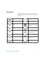
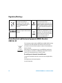
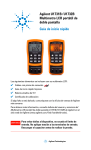
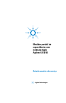
Agilent U1731B/U1732B
Dual Display Handheld
LCR Meter
User’s and Service Guide
Agilent Technologies
Notices
© Agilent Technologies, Inc. 2009 – 2012
Warranty
No part of this manual may be reproduced in
any form or by any means (including electronic storage and retrieval or translation
into a foreign language) without prior agreement and written consent from Agilent
Technologies, Inc. as governed by United
States and international copyright laws.
The material contained in this document is provided “as is,” and is subject to being changed, without notice,
in future editions. Further, to the maximum extent permitted by applicable
law, Agilent disclaims all warranties,
either express or implied, with regard
to this manual and any information
contained herein, including but not
limited to the implied warranties of
merchantability and fitness for a particular purpose. Agilent shall not be
liable for errors or for incidental or
consequential damages in connection with the furnishing, use, or performance of this document or of any
information contained herein. Should
Agilent and the user have a separate
written agreement with warranty
terms covering the material in this
document that conflict with these
terms, the warranty terms in the separate agreement shall control.
Manual Part Number
U1731-90059
Edition
Third Edition, March 21, 2012
Printed in Malaysia
Agilent Technologies, Inc.
5301 Stevens Creek Blvd.
Santa Clara, CA 95051 USA
Safety Notices
Technology Licenses
The hardware and/or software described in
this document are furnished under a license
and may be used or copied only in accordance with the terms of such license.
Restricted Rights Legend
CAUTION
A CAUTION notice denotes a hazard. It calls attention to an operating procedure, practice, or the like
that, if not correctly performed or
adhered to, could result in damage
to the product or loss of important
data. Do not proceed beyond a
CAUTION notice until the indicated
conditions are fully understood and
met.
WA R N I N G
A WARNING notice denotes a
hazard. It calls attention to an
operating procedure, practice, or
the like that, if not correctly performed or adhered to, could result
in personal injury or death. Do not
proceed beyond a WARNING
notice until the indicated conditions are fully understood and
met.
U.S. Government Restricted Rights. Software and technical data rights granted to
the federal government include only those
rights customarily provided to end user customers. Agilent provides this customary
commercial license in Software and technical data pursuant to FAR 12.211 (Technical
Data) and 12.212 (Computer Software) and,
for the Department of Defense, DFARS
252.227-7015 (Technical Data - Commercial
Items) and DFARS 227.7202-3 (Rights in
Commercial Computer Software or Computer Software Documentation).
II
U1731B/U1732B User’s and Service Guide
Safety Symbols
The following symbols on the instrument and in the documentation
indicate precautions that must be taken to maintain safe operation of the
instrument.
Direct current
Off (supply)
Alternating current
On (supply)
Both direct and alternating
current
Equipment protected throughout
by double insulation or reinforced
insulation.
Three-phase alternating current
Caution: risk of electric shock.
Earth (ground) terminal
Caution: risk of danger (refer to
this manual for specific Warning
or Caution information.
Protective conductor terminal
Caution: hot surface.
Frame or chassis terminal
Out position of a bi-stable push
control.
Equipotentiality
In position of a bi-stable push
control.
U1731B/U1732B User’s and Service Guide
III
Regulatory Markings
The CE mark is a registered
trademark of the European
Community. This CE mark shows
that the product complies with all
the relevant European Legal
Directives.
The C-tick mark is a registered
trademark of the Spectrum
Management Agency of Australia. This
signifies compliance with the Australia
EMC Framework regulations under the
terms of the Radio Communication Act
of 1992.
ICES/NMB-001 indicates that this
ISM device complies with Canadian
ICES-001.
This instrument complies with the
WEEE Directive (2002/96/EC) marking
requirement. This affixed product label
indicates that you must not discard this
electrical/electronic product in
domestic household waste.
Waste Electrical and Electronic Equipment (WEEE) Directive
2002/96/EC
This instrument complies with the WEEE Directive (2002/96/EC) marking
requirement. This affixed product label indicates that you must not
discard this electrical/electronic product in domestic household waste.
Product Category:
With reference to the equipment types in the WEEE directive Annex 1,
this instrument is classified as a “Monitoring and Control Instrument”
product. The affixed product label is shown as below:
Do not dispose in domestic household waste
To return this unwanted instrument, contact your nearest Agilent office,
or visit:
www.agilent.com/environment/product
for more information.
IV
U1731B/U1732B User’s and Service Guide
General Safety Information
The following general safety precautions must be observed during all
phases of operation, service, and repair of this instrument. Failure to
comply with these precautions or with specific warnings elsewhere in
this manual violates safety standards for design, manufacture, and
intended use of the instrument. Agilent Technologies assumes no liability
for the customer’s failure to comply with these requirements.
WA R N I N G
•
•
•
•
•
•
•
•
CAUTION
•
This meter is for indoor use at an altitude of up to 2,000 m.
The warnings and precautions should be read and well understood
before the meter is used.
Use this meter only as specified in this manual; otherwise, the
protection provided by the meter may be impaired.
When measuring in-circuit components, first de-energize the
circuits before connecting them to the test leads.
Discharge the capacitor before testing.
The meter is safety-certified in compliance with IEC 61010-1.
Use the meter only as specified in this manual. Otherwise, the
protection provided by the meter may be impaired.
The power for the meter is supplied with a single standard 9 V
battery. Line operation is also possible using a 12 VAC to DC adaptor.
If a power adaptor is selected, please be sure to meet the safety
requirements of a relevant IEC standard.
Ensure proper insertion of the battery in the LCR meter, and follow the
correct polarity.
U1731B/U1732B User’s and Service Guide
V
Environmental Conditions
This instrument is designed for indoor use in areas with low condensation
and to be used with standard or compatible test probes. Table 1 shows
general environment requirements.
Table 1
VI
Environment requirements
Environment Conditions
Requirements
Operating environment
0 °C to 40 °C; 0 – 70% R.H.
Storage humidity
0 – 80% R.H. non condensing
Storage environment
–20 °C to +50 °C; 0 – 80% R.H.
Altitude
0 – 2,000 meters
Pollution degree
Pollution degree 2
U1731B/U1732B User’s and Service Guide
CAUTION
The U1731B/U1732B dual display handheld LCR meter complies with
the following safety and EMC requirements:
•
•
•
•
•
•
•
•
•
•
CAUTION
IEC 61010-1:2001/EN 61010-1:2001 (2nd Edition)
CISPR 11:2003+A1:2004
IEC 61000-4-2:1995+A1:1998 +A2:2000
IEC 61000-4-3:2006
IEC 61000-4-4:2004
IEC 61000-4-5:2005
IEC 61000-4-6:2003+A1:2004+A2:2006
IEC 61000-4-11:2004
Canada: ICES/NMB-001:2004
Australia/New Zealand: AS/NZS CISPR11:2004
Degradation of some product specifications can occur in the presence
of ambient electromagnetic (EM) fields and noise that affects the
product's power line, communication, or I/O cables. The product
self-recovers and operates to all specifications when:
• the source of the ambient EM field and noise is removed,
• the product is protected from the ambient EM field, or
• the product cabling is shielded from the ambient EM noise.
U1731B/U1732B User’s and Service Guide
VII
Declaration of Conformity (DoC)
The Declaration of Conformity (DoC) for this instrument is available on the Web
site. You can search the DoC by its product model or description.
http://regulations.corporate.agilent.com/DoC/search.htm
NOTE
VIII
If you are unable to search for the respective DoC, please contact your local
Agilent representative.
U1731B/U1732B User’s and Service Guide
In This Guide…
1
Getting Started Chapter 1 introduces key features and steps to get started
with a U1731B/U1732B dual display handheld LCR meter. This chapter also
guides you through the basics of the front panel operations.
2
Features and Functions Chapter 2 explains how to set up connections to
perform meter measurements. It also describes the features and functions that
are available in the U1731B/U1732B dual display handheld LCR meter in
step-by-step instructions.
3
Service and Maintenance Chapter 3 explains the services and maintenance
procedures for the U1731B/U1732B dual display handheld LCR meter.
4
Specifications Chapter 4 lists the specifications and characteristics of the
U1731B/U1732B dual display handheld LCR meter.
U1731B/U1732B User’s and Service Guide
IX
X
U1731B/U1732B User’s and Service Guide
Contents
Contents
1 Getting Started
Introduction 2
Checking the Shipping Contents 3
The Front Panel at a Glance 4
Display Annunciators 5
The Keypad at a Glance 7
The Input Terminal at a Glance 8
2 Features and Functions
Inductance Measurement 10
Capacitance Measurement 11
Resistance Measurement 12
Data Hold 13
Static Recording 13
Dissipation Factor/Quality Factor/Phase Angle 13
Test Frequency 14
LCR Function Selector 14
Relative 14
Tolerance 15
Auto/Manual Range 15
Automatic Fuse Detection 16
Parallel/Series Mode 16
CAL Function 17
Enable/Disable Auto Power-Off 19
Low Battery Indication 19
Backlit Display (Only Available for U1732B) 19
Communication (Optional Accessories) 20
3 Service and Maintenance
Service 22
Battery Replacement 22
U1731B/U1732B User’s and Service Guide
XI
Contents
Fuse Replacement 24
Replacement Parts 25
Cleaning the LCR Meter 26
Specification Validation 27
4 Specifications
U1731B Electrical Specifications 26
U1732B Electrical Specifications 29
General Specifications 33
SMD Tweezers Specifications 35
XII
U1731B/U1732B User’s and Service Guide
U1731B/U1732B Dual Display Handheld LCR Meter
User’s and Service Guide
1
Getting Started
Introduction 2
Checking the Shipping Contents 3
The Front Panel at a Glance 4
Display Annunciators 5
The Keypad at a Glance 7
The Input Terminal at a Glance 8
This chapter introduces the key features and getting- started tips for the
U1731B/U1732B dual display handheld LCR meter. This chapter also
guides you through the basics of the front panel operations.
Agilent Technologies
1
1
Getting Started
Introduction
The 20,000- count dual display handheld LCR meters (U1731B and
U1732B) are special microprocessor- controlled meters for inductance,
capacitance, and resistance measurements. The LCR meter is simple to
operate and is capable of making absolute parallel mode measurements as
well as series mode measurement. The LCR meter provides direct and
accurate measurements of inductors, capacitors, and resistors with
different testing frequencies. It offers both automatic and manual range
selection.
The front panel keypad makes it convenient to select features and
functions such as data hold, maximum, minimum, and average record
mode, relative mode, tolerance sorting mode, frequency selection, and LCR
selection. The test data can be transferred to a PC via an optional full
isolated optical IR- USB interface. The U1732B offers backlight display
capability for better visibility in the dark.
A tilt stand gives you flexibility in positioning the LCR meter for viewing
and operating. The over- molding rubber case protects the LCR meter.
Single 9 V battery operation is standard for the LCR meter, but a DC 12 V
power adaptor can also be used as a power input.
2
U1731B/U1732B User’s and Service Guide
Getting Started
1
Checking the Shipping Contents
Inspect and verify that you have received the following items for the
standard purchase of the U1731B/U1732B and/or accessories that you may
have ordered. If any of the item listed below are missing, contact your
nearest Agilent Technologies sales office.
Table 1-1 List of standard and optional accessories
Type
Part Number
Standard
Accessories
Agilent U1731B/U1732B Quick Start Guide
Alligator clip leads
9 V Alkaline battery
Certificate of Calibration (CoC)
Optional
U5481A
IR to USB cable
U1780A
Power adaptor
U1782A
SMD tweezers
U1174A
Soft carrying case
U1731B/U1732B User’s and Service Guide
3
1
Getting Started
The Front Panel at a Glance
Annunciator
display
Keypad
Input
terminals
U1731B
U1732B
Figure 1-1 Front panel of U1731B and U1732B dual display handheld LCR meter
4
U1731B/U1732B User’s and Service Guide
Getting Started
1
Display Annunciators
8
9
10 11 12 13 14
15
16
17
18
19
7
6
5
20
21
22
23
24
25
4
3
2
1
Figure 1-2 LCD display
Table 1-1 Descriptions of each annunciator
No.
Symbols
Descriptions
1
Low battery indicator
2
Reading out of LO limit
3
Primary display
4
Reading out of HI limit
5
Auto power off indicator
6
7
8
TOL 1% 5% 10% 20%
Tolerance mode, to set 1%, 5%, 10%, and 20% for sorting
capacitance
AUTO
AUTO range
C
Inductance, Capacitance, or Resistance (L,C, or R) function
indicator
U1731B/U1732B User’s and Service Guide
5
1
Getting Started
MAX AVG MIN
Static recording mode
MAX: Maximum reading
9
AVG: Average reading
MIN: Minimum reading
10
REL
Relative mode
11
DH
Data hold to hold the displayed digital value
12
q
Phase angle indicator (only applicable for U1732B)
13
D
Dissipation factor indicator
14
Q
Quality factor indicator
15
Secondary display
16
Audible alert for tolerance and compare mode
17
%
Unit for tolerance display (percentage)
18
deg
Unit for phase angle (degree) (only applicable for U1732B)
19
kHz
Unit for beeper frequency as setup mode
20
PAL
Parallel mode indicator
21
SER
Series mode indicator
22
mkW
Unit for resistance (kΩ and MΩ)
23
Unit for inductance (µH and mH)
24
Unit for capacitance (pF, nF, µF, and mF)
25
Remote control
Special indication characters
6
Descriptions
Descriptions
Indicates short connectors
Indicates calibration mode
Indicates open connectors
Indicates damaged or open
fuse
U1731B/U1732B User’s and Service Guide
Getting Started
1
The Keypad at a Glance
9
1
8
2
7
3
6
4
5
Figure 1-3 Keypad of U1731B/U1732B dual display handheld LCR meter
Table 1-2 Keypad descriptions and functions
No. Keys
1
Functions
Power
To turn ON/OFF the instrument
2
D/Q/θ
To select dissipation factor, quality factor, and phase angle display
(only applicable for U1732B)
3
L/C/R
P↔S
To select inductance, capacitance, and resistance measurement
4
TOL
Tolerance mode
5
FREQ
To select test frequency
REL
Relative mode
CAL
Calibration mode
Manual
Manual range
AUTO
Auto range
HOLD
Data hold
REC
Static recording mode
REMOTE
To toggle ON/OFF the remote function
6
7
8
9
To toggle parallel and series mode
Backlight display (only applicable for U1732B)
U1731B/U1732B User’s and Service Guide
7
1
Getting Started
The Input Terminal at a Glance
To avoid damaging this instrument, do not exceed the input limit. Do not apply
voltage to input terminals. Discharge the capacitor before testing.
WA R N I N G
2
1
3
Figure 1-4 Input terminals/sockets of U1731B/U1732B dual display handheld LCR meter
No. Terminals Functions
8
1
+
Positive terminal/socket
2
–
Negative terminal/socket
3
GUARD
Guard terminal/socket
U1731B/U1732B User’s and Service Guide
U1731B/U1732B Dual Display Handheld LCR Meter
User’s and Service Guide
2
Features and Functions
Inductance Measurement 10
Resistance Measurement 12
Data Hold 13
Static Recording 13
Dissipation Factor/Quality Factor/Phase Angle 13
Test Frequency 14
LCR Function Selector 14
Relative 14
Tolerance 15
Auto/Manual Range 15
Automatic Fuse Detection 16
Parallel/Series Mode 16
CAL Function 17
Enable/Disable Auto Power-Off 19
Low Battery Indication 19
Backlit Display (Only Available for U1732B) 19
Communication (Optional Accessories) 20
This chapters provides detailed information on the features and functions
that are available in the U1731B/U1732B dual display handheld LCR
meter.
Agilent Technologies
9
2
Features and Functions
Inductance Measurement
Figure 2-1 Inductance measurement
1 Press the
key to power- on the LCR meter.
2 Press the L/C/R key to select inductance (L) measurement.
3 Insert an inductor into component receptacle socket or connect the test
clip to the component leads as required.
4 Press the FREQ key to select testing frequency.
5 Press the D/Q or D/Q/q key to select Q factor for secondary display.
6 Read the display readings for inductance value and quality factor.
NOTE
10
It is recommended that you calibrate the LCR meter before testing to achieve optimum
precision for all L, C, and R measurements at either the highest or lowest ranges.
U1731B/U1732B User’s and Service Guide
Features and Functions 2
WA R N I N G
To avoid electrical hazards, discharge the capacitor to be tested before measuring.
Capacitance Measurement
Figure 2-2 Capacitance measurement
1 Press the
key to turn on the LCR meter.
2 Press the L/C/R key to select capacitance (C) measurement.
3 Insert a capacitor into the component receptacle socket or connect the
test clip to the component leads as required.
4 Press the FREQ key to select testing frequency.
5 Press the D/Q or D/Q/q key to select D factor for secondary display.
6 Read the display readings for capacitance value and dissipation factor.
U1731B/U1732B User’s and Service Guide
11
2
Features and Functions
Resistance Measurement
Figure 2-3 Resistance measurement
1 Press the
key to turn on the LCR meter.
2 Press the L/C/R key to select Resistance measurement.
3 Insert a resistor into the component receptacle socket or connect the
test clip to the component leads as required.
4 Press the FREQ key to select testing frequency.
5 Read the display readings for resistance value.
12
U1731B/U1732B User’s and Service Guide
Features and Functions 2
Data Hold
The data- hold function allows the user to freeze the display. To enter this
mode, press the HOLD key. Press the key again to release.
Static Recording
Press the REC key for more than one second to enter the static recording
mode. The maximum and minimum readings are then stored in memory.
The beeper will beep once when a new reading has been recorded. Press
the same key to cycle through the maximum, minimum, and average of the
present readings.
The MAX, MIN, or AVG annunciator will appear on the display to indicate
which value is being displayed. Whenever the MAX AVG MIN anunciators
appear on the display simultaneously, the display reading is always a
present value.
To exit this mode, press and hold the key for more than one second.
NOTE
1 Static recording captures only stable values and updates the memory; it will not record any
overload (OL) value for any of the LCR functions. In addition, the LCR meter will not record values
below 50 counts in capacitance measurement.
2 Static recording is only available in manual ranging; however, activation while in auto-ranging will
automatically set the LCR meter to manual ranging and cause calibration prompts to be displayed
in the recommended ranges.
Dissipation Factor/Quality Factor/Phase Angle
The D/Q/ q values can be displayed interchangeably by pressing the D/Q/
q key when the LCR meter is set to inductance or capacitance mode. This
setting does not apply to resistance measurement. The phase angle mode
(q) is only available for the U1732B.
U1731B/U1732B User’s and Service Guide
13
2
Features and Functions
Test Frequency
The testing frequency is set to 1 kHz by default. Press the FREQ key to
select the desired test frequency.
LCR Function Selector
Press the L/C/R key to select the L, C, or R function as desired.
Relative
Press the REL key to enter the relative mode and store the display
reading as a reference value. It will then display all subsequent readings
relative to reference value. Press the key again to exit the relative mode.
NOTE
14
1 The relative mode cannot be activated if the display value is either "OL" or "0000".
2 Relative mode is only available in manual ranging; however, activation while in auto-ranging will
automatically set the LCR meter to manual ranging and cause calibration prompts to be displayed
in the recommended ranges.
3 The relative mode cannot be activated if the LCR meter is set at auto-ranging with data hold
activated.
U1731B/U1732B User’s and Service Guide
Features and Functions 2
Tolerance
The tolerance ranges available are 1%, 5%, 10%, and 20%. To enter
tolerance mode, insert the appropriate component as a standard value into
the socket or connect the component to the test probes, then press the
TOL key to set this value, as the standard reference tolerance. Similarly,
any value which appears on the display, such as DH or MAX/MIN/AVG,
can be used as a standard value to sort components. Press this key again
to cycle through 1%, 5%, 10% and 20% tolerance as desire.
This function is designed for convenient component sorting. The beeper
will beep three times whenever the component under test exceeds the
setting tolerance. Conversely, when the beeper beeps once, this indicates
that the component is within the setting tolerance.
NOTE
1 The tolerance mode cannot be activated if "OL” or "0000" is shown on the display or when the
tested capacitance value is below 10 counts.
2 Tolerance mode is only available in manual ranging; however, activation while in auto-ranging will
automatically set the LCR meter to manual ranging and cause calibration prompts to be displayed
in the recommended ranges.
3 The tolerance mode cannot be activated if the LCR meter is set to auto-ranging with data hold
mode activated.
4 The 20% tolerance selection is only available for U1732B.
Auto/Manual Range
The LCR meter is set to auto- ranging mode by default when the meter is
powered- on. For specific measurement, press AUTO/MANUAL key to
select manual ranging. To return to the auto- ranging mode, press and hold
the AUTO/MANUAL key for more than one second.
U1731B/U1732B User’s and Service Guide
15
2
Features and Functions
Automatic Fuse Detection
When the LCR meter detects that the protective fuse is open or damaged,
the FUSE character (as shown in Figure 2- 4) will appear on the display
and the beeper will beep continuously. In this situation, none of the
function keys can be operated and all other LCR meter functions will be
discontinued. Fuse replacement is required. To replace protective fuse,
refer to Chapter 3, “Fuse Replacement”.
Figure 2-4 Fuse detection
Parallel/Series Mode
The LCR meter can display parallel (PAL) and series (SER) mode data for
all ranges. For capacitance and resistance measurements, the LCR meter is
set to parallel mode by default. Series mode is the default setting for
inductance measurement. Press the L/C/R key for more than one second
to toggle PAL and SER mode.
16
U1731B/U1732B User’s and Service Guide
Features and Functions 2
CAL Function
The CAL function is a correction function which enables the LCR meter's
internal parameters and external connector residues to be offset
(corrected) to achieve measurements with higher accuracy. The CAL
function is only available for extremely high or low L, C, and R ranges.
It is highly recommended that you correct extremely high or low ranges
for L, C, and R before making precision measurements. Correction (CAL)
prompts will be displayed automatically every time these ranges are
manually or functionally selected, (e.g. REL, TOL, REC, etc.) and therefore
correction is recommended.
Figure 2-5 Open calibration and short calibration
Measurements performed in extremely high or low ranges that require
corrections are predefined as “open cal” or “short cal”. Refer to the
“Specified Note” column of any of the L, C, or R measurement from
Chapter 4, “U1731B Electrical Specifications,” starting on page 26 or
Chapter 4, “U1732B Electrical Specifications,” starting on page 29 to find
out which of these measurement ranges are indicated with “After open
cal” or “After short cal”. These predefined ranges will require you to
connect the terminal connection as “open” or “short” to achieve the
accuracy in the table.
U1731B/U1732B User’s and Service Guide
17
2
Features and Functions
Follow the instructions below to perform the CAL function:
1 Press and hold the CAL key for more than one second to enter CAL
mode.
2 CAL prompts will be shown on the display.
3 Press the MANUAL key to select the desired range for correction. Follow
the prompts instruction on the upper right of the display of the
selected range for the terminal connection. Leave the positive and
negative connector terminals open for open connector (OPn) connection,
or short the connector terminals at short connector (Srt) connection.
4 Press the CAL key to start the correction function. The OPn or Srt
annunciator on the upper right of the display will disappear to indicate
the start of the correction process.
To skip the correction process, press D/Q/θ.
5 The CAL annunciator on the main display will disappear once the
correction process is completed. The LCR meter will be restored to the
normal display and ready to perform measurement.
NOTE
18
1 Changing measurement frequencies is handled the same way as selecting a different hardware
range, and the automatic calibration prompts will be displayed in the recommended ranges.
2 Ensure that the same testing position is used after short calibration.
U1731B/U1732B User’s and Service Guide
Features and Functions 2
Enable/Disable Auto Power-Off
When the LCR meter has not been used for five minutes since the last
operation, the beeper will beep a long tone. Then the LCR meter will
automatically enter sleep mode and none of the anunciators will shown on
the display. To re- activate the LCR meter, press any key.
When the LCR meter must be used for a longer period, the auto power- off
function can be disabled. To disable auto power- off, press and hold the
L/C/R key while turning LCR meter ON. Release the L/C/R key and press
any key again. The
annunciator will disappear. This will confirm
that the auto power- off function has been disabled.
When a 12 VAC adaptor is used as an optional power source, the auto
power- off function is automatically disabled.
NOTE
It is recommended that the LCR meter should always be powered off when not in use.
Low Battery Indication
When the
annunciator is blinking on the display, this shows that the
battery voltage is below normal working voltage and is weakening. Replace
the battery with a new battery to maintain the precision of the LCR
meter. To replace the battery, refer to Chapter 3, “Battery Replacement”.
Backlit Display (Only Available for U1732B)
Press and the hold
key for more than one second to toggle
backlit ON/OFF. This function is only available for the U1732B.
U1731B/U1732B User’s and Service Guide
19
2
Features and Functions
Communication (Optional Accessories)
The LCR meter can be adapted for communication capability. The optional
IR- USB package comes with a full optically- isolated cable and software.
This function enables you to record data easily. To use this function, you
will need a U1173A IR- to- USB cable (purchased separately) and the data
logging software. You can download the data logging software from the
Agilent web site at: http://www.agilent.com.find/hhTechlib. Refer to the
following procedure to set up the communication between your LCR meter
and personal computer (PC).
1 Connect one side of the cable to the meter with the Agilent logo facing
up and connect the USB connector to the PC.
2 Press the REMOTE key to enable this interface; the
annunciator will be shown on the display.
3 Run the Data Logger software to transfer the data to the PC for your
applications.
4 To remove the cable, press and pull the snap ends on each side of the
cable that is connected to the meter.
The side with the Agilent
logo must be facing up
Connect to the PC’s USB port
Press the snaps to remove
the cable
Figure 2-6 Cable connection for remote communication
20
U1731B/U1732B User’s and Service Guide
U1731B/U1732B Dual Display Handheld LCR Meter
User’s and Service Guide
3
Service and Maintenance
Service 22
Battery Replacement 22
Fuse Replacement 24
Replacement Parts 25
Cleaning the LCR Meter 26
Specification Validation 27
This chapter describes the service and maintenance procedures for the
U1731B/U1732B dual display handheld LCR meter. Repair or service that
are not covered in this manual should only be performed by qualified
personnel.
Agilent Technologies
21
3
Service and Maintenance
Service
WA R N I N G
To avoid electrical shock, do not perform any service unless you are qualified to do so.
If the instrument fails to operate, check the battery and test leads.
Replace the battery or test leads if necessary. If the instrument still
cannot function, check again the operating procedures described in this
instruction manual. When servicing, use specified replacement parts only.
The LCR meter must be completely turned off while replacing either the
fuse or battery.
Battery Replacement
WA R N I N G
Do not discharge the battery by shorting the battery or reversing the battery polarity.
CAUTION
To avoid instruments being damage from battery leakage:
• Always remove dead batteries immediately.
• Always remove the battery and store it separately if the LCR meter is not going to be
used for a long period.
The LCR meter is powered by a single 9 V alkaline battery. Replace the
battery if the low battery sign (
) is displayed and flashing. Use the
following procedures to replace the battery.
1 Loosen screws with a suitable screwdriver and remove the battery cover
as shown in Figure 3- 1.
2 Replace the degraded battery with a new battery.
22
U1731B/U1732B User’s and Service Guide
Service and Maintenance
3
Battery cover screw
Figure 3-1 Battery replacement
U1731B/U1732B User’s and Service Guide
23
3
Service and Maintenance
Fuse Replacement
NOTE
Users should use clean/dry gloves when performing fuse replacement. Do not touch any
components except the fuse and plastic parts. No recalibration is required after replacing
the fuse.
The LCR meter is able to self- detect if the input protective fuse is either
open or damaged. In this case, the display will show FUSE and beep will
sound continuously, warning the user to replace the damaged fuse to
maintain the accuracy of measurement. While replacing the fuse, the LCR
meter must be completely turned off.
1 Loosen screws with a suitable screwdriver and remove the battery cover
as shown in Figure 3- 1.
2 Loosen screws with a suitable screwdriver and remove the bottom cover
as shown in Figure 3- 2.
3 Replace the damaged fuse with the a new fuse as specified in
Chapter 4, “General Specifications”.
Bottom cover screw
Battery cover screw
Figure 3-2 Fuse replacement
24
U1731B/U1732B User’s and Service Guide
Service and Maintenance
3
Replacement Parts
This section explains how to order replacement parts for your instrument.
To order replaceable parts
You can order replaceable parts from Agilent using the Agilent part
number. Note that not all parts listed in this chapter are available as
field–replaceable parts. To order replaceable parts from Agilent, do the
following.
1 Contact your nearest Agilent sales office or service center.
2 Identify the parts by the Agilent part number shown in the replaceable
parts list.
3 Provide the instrument model number and serial number.
Table 3-1 Replaceable parts
Part Number
Description
A02-62-25612-2U
Fuse
U1731B/U1732B User’s and Service Guide
25
3
Service and Maintenance
Cleaning the LCR Meter
WA R N I N G
To avoid electrical shock or damage to the LCR meter, never contact with water
inside the case.
Before cleaning the LCR meter, ensure that the LCR meter’s power is
completely turned off and remove the external DC adaptor. To clean the
LCR meter, wipe the dirty parts with gauze or soft cloth soaked mildly in
diluted neutral detergent. After cleaning, ensure that the instrument is
completely dried before using.
26
U1731B/U1732B User’s and Service Guide
Service and Maintenance
3
Specification Validation
You can perform self- validation of the LCR meter's accuracy by using the
recommended equipment with the specified test ranges below.
Table 3-1 Resistance ranges for functional validation
Resistance (Parallel Mode), Test Frequency: 100 Hz, 120 Hz, 1000 Hz, or 10 kHz
Recommended Equipment: IET 1433 Resistor Box
Range (W)
Test Value Used
200 k
100 k
2000
1000
20
10
Table 3-2 Capacitance ranges for functional validation
Capacitance (Parallel Mode), Test Frequency: 100 Hz, 120 Hz, 1000 Hz, or 10 kHz
Recommended Equipment: HACS-Z Precision
Decade Capacitor
Range (F)
Test Value Used
20 µ
10 µ
200 n
100 n
20 n
10 n
200 p*
100 p
* Does not support test frequency of 100 Hz, 120 Hz,
and 1000 Hz
U1731B/U1732B User’s and Service Guide
27
3
Service and Maintenance
Table 3-3 Inductance ranges for functional validation
Inductance (Series Mode), Test Frequency: 100 Hz, 120 Hz, 1000 Hz, or 10 kHz
Recommended Equipment: GR1491 Precision
Decade Inductor
Range (H)
Test Value Used
200 m
100 m
20 m
10 m
2000 µ*
1000 µ
* Does not support test frequency of 100 Hz and 120
Hz
28
U1731B/U1732B User’s and Service Guide
U1731B/U1732B Dual Display Handheld LCR Meter
User’s and Service Guide
4
Specifications
U1731B Electrical Specifications 26
U1732B Electrical Specifications 29
General Specifications 33
SMD Tweezers Specifications 35
This chapter contains the U1731B/U1732B dual display handheld LCR
meter’s electrical and general specifications.
Agilent Technologies
25
4
Specifications
U1731B Electrical Specifications
Accuracy is expressed as ± (% of reading + number of least significant
digits) at 23 °C ± 5 °C and <75% R.H.
Resistance (Parallel Mode), Test Frequency =120 Hz/1 kHz
Range
10 MW
2000 KW
200 KW
20 KW
2000 W
200 W
20 W
Maximum
Display
9.999 MW
1999.9 KW
199.99 KW
19.999 KW
1999.9 W
199.99 W
19.999 W
Accuracy
@ 120 Hz
2.0% + 8*
0.5% + 5
0.5% + 3
0.5% + 3
0.5% + 3
0.8% + 5
1.2% + 40
@ 1 kHz
2.0% + 8*
0.5% + 5
0.5% + 3
0.5% + 3
0.5% + 3
0.8% + 5
1.2% + 40
Specified Note
After open cal.
After open cal.
After short cal.
After short cal.
* This specification is based on the battery operation.
NOTE
1 This specification is based on the measurement performed at the test socket.
2 Device Under Test (DUT) and test leads need to be properly shielded to GUARD if necessary.
Capacitance (Parallel Mode), Test Frequency =120 Hz
Range
10 mF
1000 µF
200 µF
20 µF
2000 nF
200 nF
20 nF
Maximum
Display
19.99 mF*
1999.9 µF†
199.99 µF
19.999 µF
1999.9 nF
199.99 nF
19.999 pF
Accuracy
Capacitance
3.0% +5 (DF<0.1)
1.0% + 5 (DF<0.1)
0.7% + 3 (DF<0.5)
0.7% + 3 (DF<0.5)
0.7% + 3 (DF<0.5)
0.7% + 5 (DF<0.5)
1.0% + 5 (DF<0.1)
DF
10% + 100/Cx + 5 (DF<0.1)
2.0% + 100/Cx + 5 (DF<0.1)
0.7% + 100/Cx +5 (DF<0.5)
0.7% + 100/Cx + 5 (DF<0.5)
0.7% + 100/Cx + 5 (DF<0.5)
0.7% + 100/Cx + 5 (DF<0.5)
2.0% + 100/Cx + 5 (DF<0.1)
Specified Note
After short cal.
After short cal.
After open cal.
After open cal.
* This reading can be extended up to 1999 MAX display with accuracy that is not specified.
† This reading can be extended up to 19999 MAX display with accuracy that is not specified.
26
U1731B/U1732B User’s and Service Guide
Specifications
4
Capacitance (Parallel Mode), Test Frequency =1 kHz
Range
1 mF
200 µF
20 µF
2000 nF
200 nF
20 nF
2000 pF
Maximum
Display
1.999 mF*
199.99 µF
19.999 µF
1999.9 µF
199.99 nF
19.999 nF
1999.9 pF
Accuracy
Capacitance
3.0% + 5 (DF<0.1)
1.0% + 5 (DF<0.1)
0.7% + 3 (DF<0.5)
0.7% + 3 (DF<0.5)
0.7% + 3 (DF<0.5)
0.7% + 5 (DF<0.5)
1.0% + 5 (DF<0.1)
DF
10.0% + 100/Cx +5 (DF<0.1)
2.0%+ 100/Cx +5 (DF<0.1)
0.7% + 100/Cx +5 (DF<0.5)
0.7% + 100/Cx +5 (DF<0.5)
0.7% + 100/C x+5 (DF<0.5)
0.7% + 100/Cx +5 (DF<0.5)
2.0% + 100/Cx +5 (DF<0.1)
Specified Note
After short cal.
After short cal.
After open cal.
After open cal.
* This reading can be extended up to 1999 MAX display with accuracy that is not specified.
NOTE
NOTE
1
2
3
4
Q value is the reciprocal of DF.
This specification is based on the measurement performed at the test socket.
Device Under Test (DUT) and test leads need to be properly shielded to GUARD if necessary.
Cx = Counts of displayed C value, e.g. C = 88.88 µF then Cx = 8888.
It is recommended to set the test frequency to 1 kHz for a mult-layer ceramic capacitor of 10 μF
and below.
Inductance (Series Mode), Test Frequency =120 Hz
Range
1000 H
200 H
20 H
2000 mH
200 mH
20 mH
Maximum
Display
999.9 H
199.99 H
19.999 H
1999.9 mH
199.99 mH
19.999 mH
Accuracy
Inductance
DF
1.0% + (Lx/10000)% +5
2.0% + 100/Lx + 5
0.7% + (Lx/10000)% +5
1.2% + 100/Lx + 5
0.7% + (Lx/10000)% +5
1.2% + 100/Lx + 5
0.7% + (Lx/10000)% +5
1.2% + 100/Lx + 5
1.0% + (Lx/10000)% +5
3.0% + 100/Lx + 5
2.0% + (Lx/10000)% +5
10.0% + 100/Lx + 5
U1731B/U1732B User’s and Service Guide
Specified Note
After open cal.
After short cal.
After short cal.
27
4
Specifications
Inductance (Series Mode), Test Frequency =1 kHz
Range
100 H
20 H
2000 mH
200 mH
20 mH
2000 µH
NOTE
28
Maximum
Display
99.99 H
19.999 H
1999.9 mH
199.99 mH
19.999 mH
1999.9 µH
1
2
3
4
Accuracy
Inductance
DF
1.0% + (Lx/10000)% +5
2.0% + 100/Lx + 5
0.7% + (Lx/10000)% +5
1.2% + 100/Lx + 5
0.7% + (Lx/10000)% +5
1.2% + 100/Lx + 5
0.7% + (Lx/10000)% +5
1.2% + 100/Lx + 5
1.0% + (Lx/10000)% +5
3.0% + 100/Lx + 5
2.0% + (Lx/10000)% +5
10.0% + 100/Lx + 5
Specified Note
After open cal.
After short cal.
After short cal.
Q value is the reciprocal of DF.
This specification is based on the measurement performed at the test socket.
Device Under Test (DUT) and test leads need to be properly shielded to GUARD if necessary.
Lx = Counts of displayed L value, e.g. L = 88.88 H then Lx = 8888.
U1731B/U1732B User’s and Service Guide
Specifications
4
U1732B Electrical Specifications
Accuracy is expressed as ± (% of reading + number of least significant
digits) at 23 °C ± 5 °C and <75% R.H.
Resistance (Parallel Mode), Test Frequency = 100 Hz/120 Hz
Range
10 MW
2000 kW
200 kW
20 kW
2000 W
200 W
20 W
Maximum
Display
9.999 MW
1999.9 kW
199.99 kW
19.999 kW
1999.9 W
199.99 W
19.999 W
Accuracy
@ 100 Hz
2.0% + 8*
0.5% + 5
0.5% + 3
0.5% + 3
0.5% + 3
0.8% + 5
1.2% + 40
@ 120 Hz
2.0% + 8*
0.5% + 5
0.5% + 3
0.5% + 3
0.5% + 3
0.8% + 5
1.2% + 40
Specified Note
After open cal.
After open cal.
After short cal.
After short cal.
* This specification is based on the battery operation.
Resistance (Parallel Mode), Test Frequency = 1 kHz/10 kHz
Range
10 MW
2000 kW
200 kW
20 kW
2000 W
200 W
20 W
Maximum
Display
9.999 MW
1999.9 kW
199.99 kW
19.999 kW
1999.9 W
199.99 W
19.999 W
Accuracy
@ 1 kHz
2.0% + 8*
0.5% + 5
0.5% + 3
0.5% + 3
0.5% + 3
0.8% + 5
1.2% + 40
@ 10 kHz
3.5% + 10*
2.0% + 10
1.5% + 5
1.5% + 5
1.5% + 5
2.0% + 10
2.5% + 200
Specified Note
After open cal.
After open cal.
After short cal.
After short cal.
* This specification is based on the battery operation.
NOTE
1 This specification is based on the measurement performed at the test socket.
2 Device Under Test (DUT) & test leads needs to be properly shielded to GUARD if necessary.
U1731B/U1732B User’s and Service Guide
29
4
Specifications
Capacitance (Parallel Mode), Test Frequency = 100 Hz/120 Hz
Range
10 mF
1000 µF
200 µF
20 µF
2000 nF
200 nF
20 nF
Maximum
Display
19.99 mF*
1999.9 µF†
199.99 µF
19.999 µF
1999.9 nF
199.99 nF
19.999 nF
Accuracy
Capacitance
3.0% + 5 (DF<0.1)
1.0% + 5 (DF<0.1)
0.7% + 3 (DF<0.5)
0.7% + 3 (DF<0.5)
0.7% + 3 (DF<0.5)
0.7% + 5 (DF<0.5)
1.0% + 5 (DF<0.1)
DF
10.0% + 100/Cx + 5 (DF<0.1)
2.0% + 100/Cx + 5 (DF<0.1)
0.7% + 100/Cx + 5 (DF<0.5)
0.7% + 100/Cx + 5 (DF<0.5)
0.7% + 100/Cx + 5 (DF<0.5)
0.7% + 100/Cx + 5 (DF<0.5)
2.0% + 100/Cx + 5 (DF<0.1)
Specified Note
After short cal.
After short cal.
After open cal.
After open cal.
* This reading can be extended up to 1999 MAX display with accuracy that is not specified.
† This reading can be extended up to 19999 MAX display with accuracy that is not specified.
Capacitance (Parallel Mode), Test Frequency = 1 kHz
Range
1 mF
200 µF
20 µF
2000 nF
200 nF
20 nF
2000 pF
Maximum
Display
1.999 mF*
199.99 µF
19.999 µF
1999.9 nF
199.99 nF
19.999 nF
1999.9 pF
Accuracy
Capacitance
3.0% + 5 (DF<0.1)
1.0% + 5 (DF<0.1)
0.7% + 3 (DF<0.5)
0.7% + 3 (DF<0.5)
0.7% + 3 (DF<0.5)
0.7% + 5 (DF<0.5)
1.0% + 5 (DF<0.1)
DF
10% + 100/Cx + 5 (DF<0.1)
2.0% + 100/Cx + 5 (DF<0.1)
0.7% + 100/Cx + 5 (DF<0.5)
0.7% + 100/Cx + 5 (DF<0.5)
0.7% + 100/Cx + 5 (DF<0.5)
0.7% + 100/Cx + 5 (DF<0.5)
2.0% + 100/Cx + 5 (DF<0.1)
Specified Note
After short cal.
After short cal.
After open cal.
After open cal.
* This reading can be extended up to 1999 MAX display with accuracy that is not specified.
30
U1731B/U1732B User’s and Service Guide
Specifications
4
Capacitance (Parallel Mode), Test Frequency = 10 kHz
Range
Maximum
Display
50 µF
20 µF
2000 nF
200 nF
20 nF
2000 pF
200pF
NOTE
NOTE
50.0 µF
19.999 µF
1999.9 nF
199.99 nF
19.999 nF
1999.9 pF
199.99 pF
1
2
3
4
Accuracy
Capacitance
3.0% + 8 (DF<0.1)
3.0% + 6 (DF<0.2)
1.5% + 5 (DF<0.5)
1.5% + 5 (DF<0.5)
1.5% + 5 (DF<0.5)
2.0% + 6 (DF<0.5)
3.0% + 8 (DF<0.1)
DF
12.0% + 100/Cx + 10 (DF<0.1)
5.0% + 100/Cx + 8 (DF<0.2)
1.5% + 100/Cx + 6 (DF<0.5)
1.5% + 100/Cx + 6 (DF<0.5)
1.5% + 100/Cx + 6 (DF<0.5)
3.0% + 100/Cx + 6 (DF<0.1)
5.0% + 100/Cx + 8 (DF<0.1)
Specified Note
After short cal.
After short cal.
After open cal.
After open cal.
Q value is the reciprocal of DF.
This specification is based on the measurement performed at the test socket.
Device Under Test (DUT) and test leads need to be properly shielded to GUARD if necessary.
Cx = Counts of displayed C value, e.g. C = 88.88 µF then Cx = 8888.
It is recommended to set the test frequency to 1 kHz for a mult-layer ceramic capacitor of 10 μF
and below
Inductance (Series mode), Test Frequency = 100 Hz/120 Hz
Range
1000 H
200 H
20 H
2000 mH
200 mH
20 mH
Maximum
Display
999.9 H
199.99 H
19.999 H
1999.9 mH
199.99 mH
19.999 mH
Accuracy
Inductance
DF
1.0% + (Lx/10000)% + 5
2.0% + 100/Lx + 5
0.7% + (Lx/10000)% + 5
1.2% + 100/Lx + 5
0.7% + (Lx/10000)% + 5
1.2% + 100/Lx + 5
0.7% + (Lx/10000)% + 5
1.2% + 100/Lx + 5
1.0% + (Lx/10000)% + 5
3.0% + 100/Lx + 5
2.0% + (Lx/10000)% + 5
10.0% + 100/Lx + 5
U1731B/U1732B User’s and Service Guide
Specified Note
After open cal.
After short cal.
After short cal.
31
4
Specifications
Inductance (Series Mode), Test Frequency = 1 kHz
Range
Maximum
Display
100 H
20 H
2000 mH
200 mH
20 mH
2000 µH
99.99 H
19.999 H
1999.9 mH
199.99 mH
19.999 mH
1999.9 µH
Accuracy
Inductance
DF
1.0% + (Lx/10000)% + 5
2.0% + 100/Lx + 5
0.7% + (Lx/10000)% + 5
1.2% + 100/Lx + 5
0.7% + (Lx/10000)% + 5
1.2% + 100/Lx + 5
0.7% + (Lx/10000)% + 5
1.2% + 100/Lx + 5
1.0% + (Lx/10000)% + 5
3.0% + 100/Lx + 5
2.0% + (Lx/10000)% + 5
10.0% + 100/Lx + 5
Specified Note
After open cal.
After short cal.
After short cal.
Inductance (Series Mode), Test Frequency = 10 kHz
Range
Maximum
Display
1000 mH
200 mH
20 mH
2000 µH
NOTE
32
999.9 mH
199.99 mH
19.999 mH
1999.9 µH
1
2
3
4
Accuracy
Inductance
2.0% + (Lx/10000)% + 8
1.5% + (Lx/10000)% + 8
1.5% + (Lx/10000)% + 10
2.0% + (Lx/10000)% + 10
DF
2.0% + 100/Lx + 10
2.0% + 100/Lx + 10
3.0% + 100/Lx + 15
8.0% + 100/Lx + 20
Specified Note
After short cal.
Q value is the reciprocal of DF.
This specification is based on the measurement performed at the test socket.
Device Under Test (DUT) & test leads need to be properly shielded to GUARD if necessary.
Lx = counts of displayed L value, e.g. L = 88.88 H, then Lx = 8888.
U1731B/U1732B User’s and Service Guide
Specifications
4
General Specifications
Table 4-4 General characteristics of U1731B and U1732B
Parameter
Power supply
U1731B
U1732B
Single standard 9 V battery (Alkaline)
External DC adaptor (DC 12 VMIN — 15 VMAX, Load 50 mA minimum)
Display
L/C/R: Maximum display 19999
D/Q: Maximum display 999 (Auto Range)
Measurements
Measuring circuit mode
L/C/R/D/Q
L/C/R/D/Q/θ
Inductance (L): Defaults to series mode
Capacitance/Resistance (C/R): Defaults to parallel mode
Ranging mode
Measuring terminals
Tolerance mode
Auto & Manual
Three terminals with sockets
1%, 5%, 10%
1%, 5%, 10%, 20%
Test signal level
Test frequency accuracy: ±0.1%
~0.6 VRMS
120 Hz = 120 Hz
100 Hz = 100 Hz
1 kHz = 1010 Hz
120 Hz = 120 Hz
1 kHz = 1010 Hz
10 kHz = 9.6 kHz
Measuring rate
1 time/s, nominal
Response time
~1 s/DUT (manual range)
Auto power-off
~5 mins without operations
Low battery indicator
~6.8 V
Operating temperature
0 °C – 40 °C
Storage temperature
Storage humidity
–20 °C – 60 °C (without battery)
0 – 80% R.H.
Relative Humidity (R.H.)
0 – 70% R.H.
Temperature coefficient
0.15 x (Specified accuracy)/°C (0 °C – 18 °C or 28 °C – 40 °C)
Battery type
Power consumption
Alkaline: ANSI/NEDA: 1604A/IEC: 6LR61
~40 mA for operation
0.08 mA after Auto Power-off
Protective fuse
Battery life
U1731B/U1732B User’s and Service Guide
0.1 A/250 V fuse (Input protective)
5 to 7 hours typical (without backlight based on new alkaline)
33
4
Specifications
Parameter
Backlight display
Weight
Dimension (W x L x H)
Safety
Warranty
U1731B
U1732B
Not available
Available
330 g
87 mm x 184 mm x 41 mm
Designed in compliance with IEC 61010-1 for Pollution Degree 2
Please refer to http://www.agilent.com/go/warranty_terms
•3 years for main unit
•3 months for standard accessories unless otherwise specified.
For the main unit, Agilent's warranty also does not cover:
•Damage from contamination
•Normal wear and tear of mechanical components
•Manuals, fuses, or standard disposable batteries
34
U1731B/U1732B User’s and Service Guide
Specifications
4
SMD Tweezers Specifications
The SMD tweezers are used for L/C/R meter and built- in banana input
terminals. The SMD tweezers are much more convenient to be used to
measure the SMD components.
It is recommended to measure the surface mount device as well as the
maximum opening of the tweezers. The tweezers have one red, one black,
and one green 4 mm shrouded plugs, which are connected to the meter's
+(H- SENSE), - (L- SENSE) and GUARD ends, respectively. The length is
approximately 770 mm (30.3) (see Figure 4- 1).
770 ± 20
8.4
150
107
Green GUARD
Red Hi/S
Black Lo/S
Figure 4-1 SMD tweezers
U1731B/U1732B User’s and Service Guide
35
4
Specifications
Electrical characteristics
Parameters
Cp
Test Condition
100 Hz
120 Hz
1 kHz
10 kHz
Tweezers Open
<5.0 pF
<5.0 pF
<5.0 pF
<5.0 pF
Tweezers Short
<0.15 Ω
<0.15 Ω
<0.15 Ω
<0.15 Ω
Tweezers Short
<1.0 µH
<1.0 µH
<1.0 µH
<1.0 µH
Parallel Capacitance
Rs
Series Resistance
Ls
Series Inductance
NOTE
1 The specification is specified at 23 °C ±5 °C and <75% R.H.
2 The tweezers are recommended to measure the SMD components for C < 200 µF or L < 20 mH or
R <10 MΩ.
Environmental condition
This tweezers is for indoor use at an altitude of up to 2,000 m.
Operation temperature: 0 °C to 50 °C, R.H. 80%.
Storage temperature: –20 °C to 60 °C.
WA R N I N G
36
To avoid electrical shock, never use wet tweezers with your
instruments.
U1731B/U1732B User’s and Service Guide
www.agilent.com
Contact us
To obtain service, warranty or technical support
assistance, contact us at the following phone
numbers:
United States:
(tel) 800 829 4444
(fax) 800 829 4433
Canada:
(tel) 877 894 4414
(fax) 800 746 4866
China:
(tel) 800 810 0189
(fax) 800 820 2816
Europe:
(tel) 31 20 547 2111
Japan:
(tel) (81) 426 56 7832 (fax) (81) 426 56 7840
Korea:
(tel) (080) 769 0800
(fax) (080) 769 0900
Latin America:
(tel) (305) 269 7500
Taiwan:
(tel) 0800 047 866
(fax) 0800 286 331
Other Asia Pacific Countries:
(tel) (65) 6375 8100
(fax) (65) 6755 0042
Or visit Agilent worldwide web at:
www.agilent.com/find/assist
Product specifications and descriptions in this
document subject to change without notice.
Always refer to the Agilent Web site for the
latest revision.
© Agilent Technologies, Inc. 2009 – 2012
Printed in Malaysia
Third Edition, March 21, 2012
U1731-90059
Agilent Technologies