1
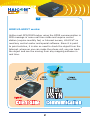
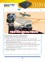
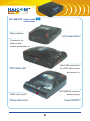
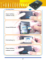
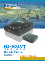
HI-601VT
G P S / G S M
Real-Time
Tracker
USER MANUAL
1
HI-601VT
1
HI-601VT GPS/GSM Tracker
INTRODUCTIONS:
With HI-601VT GPS/GSM tracker, one can track, remote
control, tapping any object globally in real time by using any
regular SIM card (with one phone number), any regular phone
(home phone, mobile phone, smart phone, etc.) and any local
mapping software or Google Earth. No any special software
needed. Because HI-601VT is small in size and main unit come
with the big capacity rechargeable battery, it is also very
suitable for personal tracking. On the HI-601VT, one can press
the “panic button” and HI-601VT will instantly dial back to the
preset telephone numbers (can set three numbers in different
priority).
With the optional car kit accessories, car control cables, microphone, moving sensor, one can remotely control certain
functions:
Car control cable sets: To stop the car oil and electricity from
any phone.
Micro-phone sets: to hear the voice from HI-601VT side.
Vibration sensor: HI-601VT will automatically dial back when
the moving occur.
1
2
HOW HI-601VT works:
Unlike most GPS/GSM tracker using the GPRS communication in
SMS message in none-real time mode and require control
station (require monthly fee) or Internet access, HI-601VT no
need any control center and special software. Since it is point
to point solution, it is also no need to check the object from the
Internet. wherever one can make the phone call, one can track
the object and see the moving from any mapping software in
real time.
2
HI-601VT
3
Just like you call someone and he tells you where the object is
and shows you where he is on the mapping software. HI-601VT
provide non-stop and continue real time tracking without time
limitation. Just like you talk to someone over the phone as long
as you can.
3
4
Step by Step operation explanations:
1. Switch power on HI-601VT main unit.
2. The GPS receiver module in HI-601VT start receive GPS
satellite signal (The GPS LED blinking means the GPS is in 3D
fixed and the data is valid)
3. The GSM module starts sending the GPS data via GSM
network back to the host side (The GSM LED blinking means
the GSM network stand by and stay on means the GSM
connected with some host)
4. Dial the Telephone number from the host side to the HI601VT main unit.
4
HI-601VT
5
5. Switch on HI-601VT decoder (Switch on the middle for data
out via wired connection and to the most right side for
wireless Bluetooth connection)
6. Connect the voice jack cable to the voice outlet from the
phone.
7. The HI-601VT A/D decoder start to decoding the Analog GPS
voice message into real-time GPS digital NMEA message.
8. On the decoder unit, connect the PS/II output cable or set up
Bluetooh connection to the display unit (such as smart
phone, PDA, laptopPC, desktopPC, etc.)
9. Using any standard NMEA mapping software, select the com
port, start GPS (just like using normal GPS receiver)
5
HI-601VT main unit
6
overview
Alarm release
SOS panic button
Connector for
data control
output and power in
Mini1394 connector
GPS status LED
for GPS data output
and power in
GPS MMCX external
GSM status LED
antenna plug
Power status LED
Power ON/OFF
6
HI-601VT
7
Getting Start
Open battery
cabinet cover
1
3
Insert SIM card
2
4
Put battery in
Close battery
cabinet cover
5
7
8
GSM LED indicator
Status
GSM Stand-by
Searching network or
no SIM card
Network connected
LED
Off 3 sec. and on 75 micro Sec.
On 600 micro sec.
and off 600 micro sec.
Stay on
Power LED indicator
Status
Battery low
External powered (Power full)
External powered - charging
GPS LED indicator
Status
Searching GPS
GPS 3D fixed
LED (Color)
Red
Green
Orange
LED
Stay on
Blinking
HI-601VT set contains two main units:
1. HI-601VT unit installed on the “client side”:
in your car, someones' back pack, etc.
2. Decoder unit carried with the “host side”
Inside HI-601VT contain five main parts: 1) SiRF StarIII high
sensitive GPS receiver module, 2) Tri-band GSM module,
3) System control circuit section, 4) Power management
section, 5) Rechargeable battery
Decoder unit contain three parts: 1) A/D converter circuit
section, 2) Bluetooth module, 3) Two 3A batteries
8
HI-601VT
9
Inside HI-601VT, the GPS module receive satellite signal and transfer
the data into standard NMEA protocol data. Then, the GSM module
transmit the data in analog voice message via regular communication
network (just like calling and talk from one phone to another phone).
As soon as these two devices communicated, HI-601VT will keep
transmitting the “voice” to the user side. By connecting the voice
phone jack cable from the users' phone to the decoder unit (the
purpose of the decoder unit is to transfer the analog voice message
into the digital NMEA standard sentences), the wireless Bluetooth
module inside will start sending the NMEA message to the display
devices, such as, PDA, laptopPC, desktopPC, etc. after the Bluetooth
connection was set up.
Track with different occasions:
1. With Smartphone:
If user has the smartphone (PDA with Bluetooth feature and phone
function), by connecting the decoder from the voice jack, one can
communicate to the HI-601VT with the smartphone and perform
the tracking on the same smartphone.
2. With PDA and mobile or home phone:
The phone set up communication to HI-601VT. Connect the voice
jack cable between the phone speaker phone jack and the decoder.
The decoder sends the NMEA sentence back to the PDA via the
Bluetooth connection.
3. With laptopPC and mobile or home phone:
The phone set up communication to HI-601VT. Connect the cable
between the phone speaker phone jack and the decoder. The
decoder sends the NMEA sentence back to the laptopPC via the
Bluetooth connection or by the cable sets.
9
10
HOW to USE Option#1
4
3
1
2
1. Decoder with smart (PDA)
phone:
1. The smart (PDA) phone calling or
communicate with the HI-601VT
2. Voice message to the decoder
3. Voice message was transferred into
standard digital NMEA protocol data
4. The NMEA data was transmitted
back to the smart (PDA) phone via
Bluetooth® connection wirelessly
10
HI-601VT
11
HOW to USE Option#2
3
1
PDA cable
2
4
1. Decoder with smart (PDA) phone:
1. The smart (PDA) phone calling or communicate
with the HI-601VT
2. Voice message to the decoder
3. Voice message was transferred into standard digital
NMEA protocol data
4. The NMEA data was transmitted back to the smart
(PDA) phone via PDA cable
11
12
HOW to USE Option#3
USB port from LaptopPC
3
1
2
4
1. Decoder with smart (PDA) phone and
laptopPC (or desktopPC):
1. The smart (PDA) phone calling or communicate
with the HI-601VT
2. Voice message to the decoder
3. Voice message was transferred into standard digital
NMEA protocol data
4. The NMEA data was transmitted to the laptopPC via
USB cable
12
HI-601VT
13
HOW to USE Option#4
Mobile Phone
3
1
4
2
1. Decoder with mobile phone and
laptopPC (or desktopPC):
1. The mobile phone calling or communicate with the
HI-601VT
2. Voice message to the decoder
3. Voice message was transferred into standard digital
NMEA protocol data
4. The NMEA data was transmitted to the laptopPC via
USB cable
13
14
HOW to USE Option#5
4
Bluetooth®
dongle
3
1
2
1. Decoder with mobile phone and
laptopPC (or desktopPC):
1. The mobile phone calling or
communicate with the HI-601VT
2. Voice message to the decoder
3. Voice message was transferred into
standard digital NMEA protocol data
4. The GPS NMEA data was
transmitted to the laptopPC via
Bluetooth® wirelessly
14
HI-601VT
15
4. With smartphone or mobile phone and track with SMS in
none-real time bases (without decoder):
The phone set up communication to HI-601VT. Press “71” and hang
up the phone. In few seconds, the phone will receive a short
message indicating the HI-601VT current coordinates. Then, go to
Google Earth or any mapping software (in none navigation mode)
and key in the coordinates. The map will point out the exact
location.
(1) Dial the number to
HI-601VT
(2) After connection,
press “71”. then, hang up.
(1)
(2)
In few seconds,
your mobile will
receive a SMS
message reqarding
to the current
location coordinate.
15
16
Key in the coordinates into the Google Earth
or any mapping software for the location
16
Key in
latitude and
longitude data
received from
SMS
HI-601VT
17
Use HI-601VT unit as a regular GPS receiver:
By connecting different kinds of optional accessory cables from
the side of HI-601VT mini1394 connector, the HI-601VT can
also be all kind regular GPS receivers.
For instance, HI-601VT can connect a HI-403BT cube and the
combination can be a regular Bluetooth GPS receiver for car
navigation. Or, connect an optional USB cable to become a USB
GPS receiver for laptopPC navigation.
Use HI-601VT as a regular Bluetooth GPS receiver
(with HI-403BT box and cigarette lighter)
17
18
HI-601VT as a regular wired GPS mouse:
By connection different optional connecting cables, HI-601VT
can be all kinds of independent wired GPS receiver solutions.
18
HI-601VT
19
ACCESSORIES:
Standard Accessories:
1. HI-601VT unit
1
2. Decoder unit
3. Voice jack/PSII to mini-1394 Y cable
4. Mini-1394 to USB power cable
5. AC power adaptor with USB plug
6. Cigarette lighter adaptor with USB plug
7. 1600 mAh Li-on rechargeable battery
8. Carrying pouch
9. Mini CD
10.User manual
5
7
6
8
9
19
10
2
3
4
20
To HI-601VT
Power LED
Optional Accessories:
1. Car control kits main unit
2. Car control cable sets
Tapping MIC
3. Micro-phone cable set
4. Vibration sensor cable set
5. HI-601VT to car kit cable
6. HI-403BTcube
DC 12V~24V
(Cigarette Lighter)
7. Mini-1394 to
PS/II (male) cable
1
To 403BT
DC 12V~2
4V
1— GND
2— Vin 12~24V
3 Vibration
4 sensor reset
5 help sw
6 panic button
7x
8— Burglar trigger
9
10 Remote Relay 2
11
12 Remote Relay 2
>
>
To Vibration Sensor
2
>
>
3
7
4
6
5
20
HI-601VT
21
Operation Easy Manual
No pass code required mode
Press “5” to enter the emergency status
Press “8” to activate the bugging under none encryption mode saving mode
activated)
Press “ * ” to stop sending voice message back and hear “du du” responding
Press “ 0 0 0 0 ” (per-setted) and
hear a long “du” verifying the pass code confirmed.
Change the pass code by pressing “ 0 1234 1234 ” (example)
pass code correct: a long “du” and pass code incorrect: du 4 times “du du du du”
Set the first set dial-back telephone number: “ 1 0912 345678*”
Setup correct: a long “du” and incorrect: du 4 times “du du du du” (anti-thief alarm)
Set the second set dial-back telephone number: “ 2 0912 345678* “
Setup correct: a long “du” and incorrect: du 4 times “du du du du” (anti-thief alarm)
Set the third set dial-back telephone number: “ 3 0912 345678* ”
Setup correct: a long “du” and incorrect: du 4 times “du du du du” (anti-thief alarm)
Remove first set dial-back telephone number: “ 1 * ”
Remove correct: a long “du” and incorrect: du 4 times “du du du du”
Remove second set dial-back telephone number: “ 2 * ”
Remove correct: a long “du” and incorrect: du 4 times “du du du du”
Remove third set dial-back telephone number: “ 3 * ”
Remove correct: a long “du” and incorrect: du 4 times “du du du du”
SOS dial-back: 4, 5, 6 three sets
Press “ # ” to stop sending voice message back and hear “du du” responding
Press “ 0 0 0 0 ” (per-setted) and hear a long “ du” verifying the pass code
confirmed.
Change the PIN code by pressing “ 0 5678 5678 ” (example)
PIN code correct: a long “du” and Cancel PIN code by pressing “ 0 # ” and a long
“du” confirm it is correct
Press “ 1 ” for temporary disable tracking encryption mode under tracking encryption
mode.
21
22
Send back data 50 times (around 3 minites ) when the set up correct.
Short message send back to the preset dial-back number by pressing
“ 21 ” “ 22 ” “ 23 ” Connection hanged up when set up correctly.
Press “ 2# ” to disable short message function
Press “ 2* ” to enable short message function (pre-setted)
Set up correct: a long “du” and incorrect: du 4 times “du du du du”
Press “ 40 ” to immediately cut off oil and electricity
Set up correct: a long “du” and incorrect: du 4 times “du du du du”
Press “ 51 ” to disable moving sensor function (pre-setted)
Press “ 52 ” to enable moving sensor function
Set up correct: a long “du” and incorrect: du 4 times “du du du du”
(Anti-thief mode can also works normally)
Press “ 54 ” to bugging without the pass code mode (pre-setted)
Press “ 55 ” to bugging with pass code required mode
Set up correct: a long “du” and incorrect: du 4 times “ du du du du”
Press “ 57 ” to tracking with no encryption required (pre-setted)
Press “ 58 ” to tracking with encryption mode
(under encryption mode, the voice message is steady tune and unable to decode it)
Set up correct: a long “du” and incorrect: du 4 times “du du du du”
Press “ 53 ” for moving sensor trigger and instant dial back (pre-setted)
Press “ 56 ” for moving sensor trigger and delay dial back
Set up correct: a long “du” and incorrect: du 4 times “du du du du”
Press “ 6* ” for GPS location dial back on certain times
Connection hanged up when set up correctly.
Press “ 6# ” for GPS location speed mode than 20 km
Connection hanged up when set up correctly.
22
HI-601VT
23
Press “ 62 ” for automatically enable dial back when GPS location speed mode than
20 km under moving sensor activated mode.
Press “ 61 ” for manually enable dial back when GPS location speed mode than 20
km under moving sensor activated mode (pre-setted)
PS: (under the activate moving sensor trigger mode 52)
Dial back testing, press “ 71 ” dial back the 1, 2, 3 sets numbers.
Press “ 8 ” for in car bugging
Under none encryption protection mode, press “ 8 ” directly without press the pass
code.
Press “ 9 ” from leaving mode back to tracking mode or not pressing any keys in 10
seconds to enable from leaving mode back to tracking mode.
After anti-thief dial back mode, take the call and dial “ * * * ” to disable the dial back
NOTE: Please press at 2 seconds intervals in each button
SMS Example:
SMS Short message
ALARM = Anti-thief trigger dial back
SENSOR = moving sensor trigger dial back
SOS = ask for help dial back
*V, N, 23” 51' 15.6, E, 120” 38' 09.6, 020. 3, 359. 9*
V = GPS last location
A = GPS current location
N, 23” 51' 15.6 = North 23” 51' 15.6
E, 120” 38' 09.6 = East 120” 38' 09.6
020.3 = Speed (sea mile)
359.9 = Direction
23
24
Dimension:
60mm
29.5mm
84mm
60mm
24
HI-601VT
25
GPS Receiver
Specifications
Chipset
SiRF Star III
Protocol
NMEA0183 GGA, GSA, GSV, RMC, GLL
Baud Rate
4800, N, 8, 1
Max. Update Rate
1 Hz
Datum
WGS84
Channel
20 channel
Frequency
L1, 1575.42MHz
Hot Start
8 sec. Average
Warm Start
38 sec. Average
Cold Start
48 sec. Average
Reacquisition Tike
100 ms
Position Accuracy
15m 2D RMS, SA off
Macimum Altitude
18,000m
Maximum velocity
515m/s
Voltage
DC 3.3V+-10%
Power consumption
90mA continuous mode
Antenna Type
Built-in active antenna
External Antenna
MMCX (Optional)
Connector
Dimension
84 (L) x 60 (W) x 29.5 (H)mm
LED Indicator
3D Positioning (blinking) or
Searching GPS (on)
25
26
GSM module features
Feature
Power saving
Charging
Frequency bands
Implementation
Minimizes power consumption in SLEEP mode to 3mA
Supports charging control for Li-lon battery
• MC55 Tri-band: EGSM 900, GSM 1800, GSM 1900
• Compliant to GSM Phase 2/2+
GSM Class
Small MS
Transmit power
• Class 4 (2W) at EGSM900 and GSM850
• Class 1 (1W) at GSM1800 and GSM1900
GPRS Connectivity
• GPRS multi-slot class 10
• GPRS mobile station class B
Temperature range
• Normal operation:
-20° C to +55° C
• Restricted operation:-25° C to -20° C & +55° C to +70° C
Temperature control • Constant temperature control prevents damage to
and auto switch-off
MC55/56 when the specified temperature is exceeded.
When an emergency call is in progress the automatic
temperature shutdown functionality is deactivated.
DATA
GPRS: • GPRS data downlink transfer: max. 85.6 kbps
• GPRS data uplink transfer: max. 42.8 kbps
• Coding scheme: CS-1, CS-2, CS-3 and CS-4
• Supports the two protocols PAP (Password
Authentication Protocol) and CHAP (Challenge
Handshake Authentication Protocol) commonly
used for PPP connections.
• Support of Packet Switched Broadcast Control Channel
(PBCCH) allows you to benefit from enhanced GPRS
performance when offered by the network operators.
CSD: • CSD transmission rates: 2.4, 4.8, 9.6, 14.4 kbps,
non-transparent, V.110
• Unstructured Supplementary services Data (USSD)
support
WAP: • WAP compliant
SMS
• MT, MO, CB, Text and PDU mode
• SMS storage: SIM card plus 25 SMS locations in the
mobile equipment
• Transmission of SMS alternatively over CSD or GPRS.
Preferred mode can be user-defined.
MMS
MMS compliant
26
HI-601VT
27
Feature
SIM interface
Implementation
• Supported SIM card: 3V
• External SIM card reader has to be connected via
interface connector
Audio interfaces
Two analog audio interfaces, one digital audio
interface(DAI)
Audio features
Speech code modes:
• Half Rate (ETS 06.20)
• Full Rate (ETS 06.10)
• Enhanced Full Rate (ETS 06.50 / 06.60 / 06.80)
• Adaptive Multi Rate (AMR)
Handsfree operation
• Echo cancellation
• Noise reduction
Two serial interfaces: • 2.65V level, bi-directional bus for AT commands and
ASC0,ASC1
data
• ASC0 - full- featured 8-wire serial interface. Supports
RTS0/CTS0 hardware handshake and software
XON/XOFF flow control. Multiplex ability according to
GSM 07.10 Multiplexer Protocol.
• ASC1 - 4-wire serial interface. Supports RTS1/CTS1
hardware handshake and software XON/XOFF flow
control.
• Baud rate: 300bps… 230kbps on ASC0 and ASC1
• Autobauding (on ASC0 only) detects 1200, 2400, 4800,
9600, 19200, 38400, 57600, 115200, 230400 bps
SIM Application
SIM Application Toolkit Supports SAT class3, GSM 11.14
Toolkit
Release 98, support of letter class ”c”
Ringing tones
Offers a choice of 7 different ringing tones / melodies,
easily selectable with AT command
Real time clock
Implemented
Timer function
Programmable via AT command
Support of TTY/CTM To benefit from TTY communication via GSM, CTM
equipment can be connected to one of the three audio
interfaces.
Firmware upgrade
Firmware upgradable over serial interface and SIM
interface
27
28
HI-601VT Decoder
How to Use:
A. Connect the inclusive phone jack/PSII to mini1394 Y cable
to the decoder: Mini1394 connector to the side of the
decoder, phone jack to the phone jack outlet)
B. As soon as turn on the power switch, the red LED light start
blinking once per second. The updated coordinates will be
sent out from “mini-1394 output” and “Bluetooth output”
each second.
PS. The data format is 4800, 8, N, 1 and computer will take the
RS232 data from COM 1, COM2 or other com port.
C. Start mapping software and activate the GPS signal
receiving. The most update location (or the last location) will
be shown on the mapping software.
D. The orange LED light (GPS in 3D fixed) followed by the red
light meaning the data is valid and is the real time location
coordinate. The status also means that the car or the person
should be in outdoor and the GPS receiver able to gets and
lock more than 4 satellites. If the yellow light not lighted
meaning the GPS data is not the real time coordinate (could
be the old location coordinate) The status also means that
the car or the person should be indoor and the GPS receiver
unable to gets and lock more than 4 satellites.
28
HI-601VT
29
Decoder LED indicator
Symbol LED Color
Orange
Bluetooth
Red
Green
Stay on
Blinking
GPS data valid
(3D fixed)
GPS data not valid
Bluetooth
Connected
Bluetooth
no connected
Decoding (4 seconds interval)
Receiving data
29