1
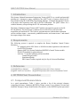
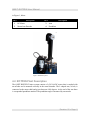
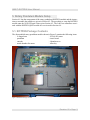
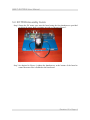
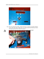
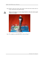
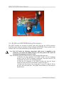
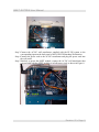
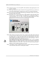
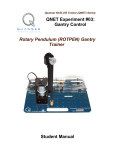
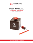
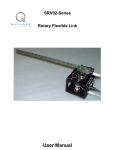
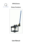
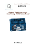
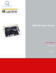
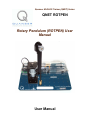
Quanser NI-ELVIS Trainer (QNET) Series: QNET ROTPEN Rotary Pendulum (ROTPEN) User Manual User Manual QNET-ROTPEN User Manual Table of Contents 1. Introduction..........................................................................................................................1 2. Requirements.......................................................................................................................1 3. References............................................................................................................................1 4. ROTPEN Plant Presentation................................................................................................1 4.1. Component Nomenclature...........................................................................................1 4.2. ROTPEN Plant Description.........................................................................................2 5. Rotary Pendulum Module Setup..........................................................................................3 5.1. ROTPEN Package Contents.........................................................................................3 5.2. ROTPEN Assembly Guide..........................................................................................4 5.3. ELVIS and ROTPEN Setup Procedure........................................................................7 5.4. LabView Controllers..................................................................................................10 Revision: 02 Page: i QNET-ROTPEN User Manual 1. Introduction The Quanser National Instruments Engineering Trainer (QNET) is a versatile and powerful training tool. Amongst its many capabilities, the QNET series of trainers allows for PC based control using the LABVIEW programming language, a National Instruments E-Series or M-Series data acquisition card, and an ELVIS workstation. The QNET allows for a scalable laboratory setup utilizing the ELVIS workstation platform.. The Rotary Pendulum Control Trainer QNET module is designed to operate on the NIELVIS platform. The ELVIS unit is connected to an NI E-Series or M-Series data acquisition card inside the PC. The Labview program interacts with the data acquisition card to read three inputs – arm encoder, pendulum encoder, and current sensor – and control the output voltage to the motor. 2. Requirements The following system is required to complete the Rotary Pendulum Control Trainer laboratory: PC equipped with an NI-E Series or NI-M-Series data acquisition card connected to an NI ELVIS station. Quanser QNET-011 Rotary Pendulum (ROTPEN) Control Trainer module. ELVIS CD installed for required drivers LabView 7.1 with the following add-ons installed: Control Design Toolkit Simulation Module PID Control Toolkit (required only for Exp #4: Inverted Pendulum) 3. References [1] NI-ELVIS User Manual. [2] QNET LabView Controllers [3] QNET Experiment #03: Gantry Control [4] QNET Experiment #04: Inverted Pendulum Control 4. ROTPEN Plant Presentation 4.1. Component Nomenclature As a quick nomenclature, Table 1, below, provides a list of the principal elements composing the Rotary Pendulum (ROTPEN) Trainer system. Every element is located and identified, through a unique identification (ID) number, on the ROTPEN plant represented Revision: 02 Page: 1 QNET-ROTPEN User Manual in Figure 1, below. ID # Description Description ID # 1 DC Motor 3 Arm 2 Motor/Arm Encoder 4 Pendulum Table 1 ROTPEN Component Nomenclature Figure 1 ROTPEN System 4.2. ROTPEN Plant Description The QNET-ROTPEN Trainer system consists of a 24-Volt DC motor that is coupled with an encoder and is mounted vertically in the metal chamber. The L-shaped arm, or hub, is connected to the motor shaft and pivots between ±180 degrees. At the end of the arm there is a suspended pendulum attached. The pendulum angle is measured by an encoder. Revision: 02 Page: 2 QNET-ROTPEN User Manual 5. Rotary Pendulum Module Setup Section 4.1 lists the components of the rotary pendulum (ROTPEN) module and the instructions to assemble the module are given in Section 4.2. The procedure to setup the ROTPEN module onto the NI ELVIS unit is then given Section 4.3. The LabView controllers associated with the ROTPEN QNET module are overviewed in Section 4.4. 5.1. ROTPEN Package Contents The disassembled rotary pendulum module shown in Figure 2 contains the following items: L-shaped arm 24-Volt DC motor pendulum circuit board. encoder 4 thumbscrews metal chamber for motor Allen key Figure 2 ROTPEN Package Contents Revision: 02 Page: 3 QNET-ROTPEN User Manual 5.2. ROTPEN Assembly Guide Step 1.Fasten the DC motor case onto the board using the four thumbscrews provided such that the motor shaft is pointing upwards, as shown in Figure 3. Figure 3 Fasten DC Motor Case on Module Step 2.As depicted in Figure 4, tighten the thumbscrews at the bottom of the board to ensure the motor case is fastened to the base board. Revision: 02 Page: 4 QNET-ROTPEN User Manual Figure 4 Tighten thumb screws to motor case Step 3.Place the pendulum assembly, which includes the L-shaped arm and the pendulum itself, on the motor shaft. Tighten the screw using the provided Allen key to fasten the bracket onto the shaft, as shown in Figure 5. Do NOT tighten the screw before placing the bracket on the shaft! Figure 5 Fasten arm pivot onto motor shaft. Revision: 02 Page: 5 QNET-ROTPEN User Manual Step 4.Finally, connect the encoder cable from the circuit board to the encoder shown in Figure 6 that measures the pendulum angle. Make sure the pins are correctly aligned and the cable and encoder signals match to one another. Figure 6 Connect encoder cable to pendulum encoder. Step 5.The completely assembled ROTPEN is shown in Figure 7. Revision: 02 Page: 6 QNET-ROTPEN User Manual Figure 7 Assembled ROTPEN system. 5.3. ELVIS and ROTPEN Setup Procedure The QNET modules are designed to quickly and easily plug into the ELVIS prototype board slot and be ready for operation. Please configure the ROTPEN Trainer system for use with the LabView virtual instruments by following the steps below. Step 1.Do NOT make the following connections while power is supplied to the hardware, even when the Standby Switch on the rear panel of the NI ELVIS Benchtop Workstation is switched to OFF. Step 2.Install the QNET ROTPEN board by completing the following steps: a) Position the large opening in the QNET board, over the mounting bracket on the NI ELVIS benchtop workstation. Note that some ELVIS workstations do not have the mounting brackets. b) Slide the PCI connector of the QNET module end into the female connector of the NI ELVIS workstation, as shown in Figure 8. c) Gently rock the board to ease it into place. It may be a tight fit, but do not force the board into place. The QNET board should now slide into the board bracket. Revision: 02 Page: 7 QNET-ROTPEN User Manual Figure 8 Fasten QNET Module onto ELVIS Step 3.Connect the AC-DC wall transformer supplied with the ELVIS system to the corresponding input on the back panel of the NI ELVIS Benchtop Workstation. Step 4.Connect the power cord to the AC-DC transformer and plug the power cord into the wall outlet. Step 5.Similarly to power the QNET module, connect the AC-DC wall transformer that was provided with the QNET module to its bulk power jack, as shown in Figure 9. Figure 9 Module Power Revision: 02 Page: 8 QNET-ROTPEN User Manual Step 6.Connect the power cord to the QNET wall transformer and plug the power cord into the wall outlet. Step 7.Before powering up the system, ensure the Prototyping Board Power switch is set to the OFF position and the Communications switch is set to the BYPASS mode. Step 8.Power the NI ELVIS Benchtop Workstation by turning the Standby Switch on the rear panel of the system to ON. Step 9.The System Power and Communications LEDs situated on the front panel of the NI ELVIS unit, as shown in Figure 10, should be lit. As depicted in Figure 9, verify also that the +15V,-15V, and +5V LEDs on the QNET module are lit. They indicate that the board has been properly connected to the ELVIS unit. Figure 10 ELVIS Front Panel Power Switch Step 10.Turn ON the Prototyping Board Power switch on the front panel of the NI ELVIS workstation. The Prototyping Board LED on the ELVIS front panel should turn bright green, see Figure 10, and the bulk power LED labeled as +B on the QNET module board should be bright green as well, as shown in Figure 9. The onboard amplifier that drives the motor is now powered. Turn OFF the Prototyping Board switch if the DC motor on the pendulum begins to turn! Any voltage applied by analog output channels #0 and #1 is amplified and delivered to the motor. Take extra care when powering the QNET module to avoid causing any damage to the motor. Step 11.The hardware setup is complete and you are now ready to load a given LabView virtual instrument and interact with the QNET module. Revision: 02 Page: 9 QNET-ROTPEN User Manual 5.4. LabView Controllers There are two Quanser LabView Virtual Instruments supplied with the QNET-ROTPEN module: QNET_ROTPEN_Lab_03_Gantry_Control.vi QNET_ROTPEN_Lab_04_Inv_Pend_Control.vi The first Quanser LabView simulates and implements a gantry control and its associated laboratory manual is QNET Experiment #03: Gantry Control. The second Quanser LabView VI implements an inverted pendulum controller and its corresponding laboratory manual is QNET Experiment #04: Inverted Pendulum Control. The QNET LabView Controllers guide gives a general explanation on the challenges involved in the gantry and inverted pendulum laboratories. Revision: 02 Page: 10