1
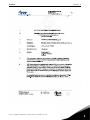
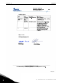
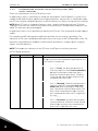
vacon® nx ac drives opt-af safe torque off & atex option board user manual vacon • 1 1. 2. 2.1. 3. 3.1. 3.2. 3.3. 3.3.1. 3.3.2. 3.3.3. 3.3.4. 3.4. 3.4.1. 3.4.2. 3.4.3. 3.4.4. 3.5. 3.5.1. 3.5.2. 3.5.3. 3.5.4. 3.5.5. 3.5.6. 3.6. 3.6.1. 4. 4.1. 4.1.1. 4.1.2. 4.2. 4.2.1. 4.2.2. 4.2.3. 4.2.4. 4.2.5. 4.2.6. TABLE OF CONTENTS Document ID:DPD00891B Revision release date: 19.12.2012 GENERAL ........................................................................................................2 INSTALLATION OF THE OPT-AF BOARD ........................................................10 OPT-AF Board layout......................................................................................................12 STO AND SS1 SAFETY FUNCTIONS................................................................13 Safe Torque Off (STO) principle......................................................................................14 Safe Stop 1 (SS1) principle .............................................................................................15 Technical details ............................................................................................................17 Response times..............................................................................................................17 Connections....................................................................................................................17 Safety-related data according to the standard .............................................................18 Technical data ................................................................................................................20 Wiring examples.............................................................................................................21 Example 1: OPT-AF board without reset for Safe Torque Off (STO) .............................21 Example 2: OPT-AF board with reset for Safe Torque Off (STO) or EN 60204-1 stop category 0...........................................................................................22 Example 3: OPT-AF board with external safety relay module with or without reset for Safe Torque Off (STO) or EN 60204-1 stop category 0 ...................................23 Example 4: OPT-AF board with external time delayed safety relay for Safe Stop 1 (SS1) or EN 60204-1 stop category 1....................................................24 Commissioning...............................................................................................................26 General wiring instructions ...........................................................................................26 Examples of cable sealing grommets or glands...........................................................26 Checklist for commissioning the OPT-AF board ...........................................................28 Parametrizing the drive for the Safe Torque Off (STO) safety functions ......................29 Parametrizing the drive and the external time delayed safety relay for Safe Stop (SS1) safety function ................................................................................30 Testing the Safe Torque Off (STO) or Safe Stop 1 (SS1) safety functions......................30 Maintenance ...................................................................................................................31 Faults related to the Safe Torque Off (STO) or Safe Stop 1 (SS1) safety functions ......31 THERMISTOR FUNCTION (ATEX) ...................................................................33 Technical data ................................................................................................................36 Functional description ...................................................................................................36 Hardware and connections ............................................................................................37 Commissioning...............................................................................................................39 General wiring instructions ...........................................................................................39 Parameter setting for ATEX function.............................................................................39 Short circuit monitoring.................................................................................................40 Exceptional use of thermistor function on OPT-AF board (similar to OPT-A3, not in compliance with ATEX directive 94/9/EC) ...........................................................40 OPT-AF board parameter ..............................................................................................41 Fault diagnosis of thermistor function ..........................................................................42 24-hour support +358 (0)201 212 575 • Email: [email protected] vacon • 2 1. GENERAL GENERAL This document covers OPT-AF option board VB00328H (or newer) and NXP Control board VB00761B (or newer). The OPT-AF option board together with NXP control board provides the following safety functions with NX family products. Safe Torque Off (STO) Hardware based ‘Safe Torque Off’ safety function to prevent the drive from generating torque on the motor shaft. STO safety function has been designed for use in accordance with the following standards: • EN 61800-5-2 Safe Torque Off (STO) SIL2 • EN ISO 13849-1: 2006 PL “d” Category 3 • EN 62061: 2005 SILCL2 • IEC 61508: 2000 SIL2 • The function also corresponds to an uncontrolled stop in accordance with stop category 0, EN 60204-1: 2006. • EN 954-1, Category 3 The STO safety function has been certified by IFA* Safe Stop 1 (SS1) SS1 safety function is realized in compliance with type C of the drives safety standard EN 61800-5-2 (Type C: “The PDS(SR) initiates the motor deceleration and initiates the STO function after an application specific time delay”). SS1 safety function has been designed for use in accordance with the following standards: • EN 61800-5-2 Safe Stop 1 (SS1) SIL2 • EN ISO 13849-1: 2006 PL"d" Category 3 • EN 62061: 2005 SILCL2 • IEC 61508: 2000 SIL2 • The function also corresponds to a controlled stop in accordance with stop category 1, EN 60204-1: 2006. The SS1 safety function has been certified by IFA * Motor Thermistor Over temperature protection (according to ATEX) Overtemperature detection using thermistor. It can be used as a tripping device for ATEX certified motors. The thermistor tripping function is certified by VTT** according to ATEX directive 94/9/EC. All safety functions of the OPT-AF board are described in this user's manual. The OPT-AF option board contains also two programmable output relays. (Note! Not part of any safety function.) NOTE! The STO function is not the same as a prevention of unexpected start-up function. For fulfilling those requirements, additional external components are required according to appropriate standards and application requirements. Required external components may be for example: • • Appropriate lockable switch A safety relay providing a reset function NOTE! The safety functions of the OPT-AF board do not comply with Emergency Switching Off according to EN 60204-1. * IFA = Institut für Arbeitsschutz der Deutsche Gesetzlichen Unfallversicherung, Germany ** VTT = Technical Research Centre of Finland 1 Tel. +358 (0) 201 2121 • Fax +358 (0)201 212 205 GENERAL vacon • 3 5 EC DECLARATION OF CONFORMITY Manufacturer's name: Vacon Plc Manufacturer's address: P.O.Box 25 Runsorintie 7 FIN-65381 Vaasa Finland We hereby declare that the safety functions of the following product Product name: Vacon OPT-AF option board to be used with Vacon NXP control board in NX family products Product Identification OPT-AF option board, VB00328H (or newer revision) NXP control board, VB00761B (or newer revision) Product Safety Functions Safe Torque Off, Safe Stop 1 (Specified in EN 61800-5-2:2007) fulfils all of the relevant safety component requirements of EC Machinery Directive 2006/42/EC. Notified body that carried out the EC type examination: IFA – Institute for Occupational Safety and Health of the German Social Accident Insurance Testing and Certification Body in BG-PRÜFZERT Alte Heerstraße 111 D-53757 Sankt Augustin Germany European notified body, Identification number 0121 IFA Certificate No: IFA 1001221 The following standards and/or technical specifications referenced below were used: EN ISO 13849-1:2006 Safety of machinery – Safety-related parts of the control systems. Part 1: General principles for design EN ISO 13849-2:2006 Safety of machinery – Safety-related parts of the control systems. Part 2: Validation EN 60204-1:2006 Safety of machinery – Electrical equipment of machines – Part 1: General requirements EN 61800-5-2:2007 Adjustable speed electrical power drive systems – Part 5-2: Safety requirements - Functional IEC 61508:2000 Functional safety of electrical/electronic/programmable electronic safety-related systems – Parts 1-7 EN 62061:2005 Safety of machinery – Functional safety of safety-related electrical, electronic and programmable electronic control systems Signature Authorised representative In Vaasa, 28.08. 2010 Vesa Laisi Janne Kuivalainen President and CEO Director, Control Platform and Products SGI 1 24-hour support +358 (0)201 212 575 • Email: [email protected] 1 vacon • 4 GENERAL 11050.emf 1 Tel. +358 (0) 201 2121 • Fax +358 (0)201 212 205 GENERAL 24-hour support +358 (0)201 212 575 • Email: [email protected] vacon • 5 1 vacon • 6 1 GENERAL Tel. +358 (0) 201 2121 • Fax +358 (0)201 212 205 GENERAL 24-hour support +358 (0)201 212 575 • Email: [email protected] vacon • 7 1 vacon • 8 GENERAL 11049.pdf 1 Tel. +358 (0) 201 2121 • Fax +358 (0)201 212 205 INSTALLATION OF THE OPT-AF BOARD 2. vacon • 10 INSTALLATION OF THE OPT-AF BOARD MAKE SURE THAT THE FREQUENCY CONVERTER IS SWITCHED OFF BEFORE AN OPTION OR FIELDBUS BOARD IS CHANGED OR ADDED! ! NOTE A Vacon NXP frequency converter with IP54 enclosure. B Remove the main cover. C Open the cover of the control unit. 24-hour support +358 (0)201 212 575 • Email: [email protected] 2 vacon • 11 INSTALLATION OF THE OPT-AF BOARD D Install OPT-AF option board in slot B on the control board of the frequency converter. Make sure that the grounding plate fits tightly in the clamp. E Cable installation: STO and SS1 safety functions require the use of cable sealing grommets or glands for all cables in the drive. The grommets or glands must be suitable for the type and amount of cables used and they shall fulfil IP54 requirements. See the User´s Manual for hole sizes for the Power cables. The hole size is PG21 (28,3 mm) for the control cables. See Chapter 3.5.2 for examples of cable sealing grommets or glands that can be used. F Close the cover of the control unit and attach the main cover. Before attaching the main cover, check that the gasket of the cover is not damaged for IP54 units. Use a tightening torque of 0,9...1,1 Nm for the main cover screws. NOTE! You can download the English and French product manuals with applicable safety, warning and caution information from www.vacon.com/downloads. REMARQUE Vous pouvez télécharger les versions anglaise et française des manuels produit contenant l’ensemble des informations de sécurité, avertissements et mises en garde applicables sur le site www.vacon.com/downloads. 2 Tel. +358 (0) 201 2121 • Fax +358 (0)201 212 205 INSTALLATION OF THE OPT-AF BOARD 2.1 vacon • 12 OPT-AF Board layout STO inputs two independent channels Thermistor input Thermistor Input: Thermistor active > 4000 ohm. After being active, the fault can be reset if resistance is < 2000 ohm. Jumper X10 for selecting thermistor short circuit supervision +24V+ +24V+24V+ SD1 SD2 +24VProgrammable Relay "NO" Programmable Relay "NO/NC" Jumper wire X12 See Chapter 4.2.4. 11052.emf Figure 1. The layout of the OPT-AF board 24-hour support +358 (0)201 212 575 • Email: [email protected] 2 vacon • 13 3. STO AND SS1 SAFETY FUNCTIONS STO AND SS1 SAFETY FUNCTIONS The safety functions of the OPT-AF board, such as the technical principle and data, wiring examples and commissioning, will be described in this chapter. NOTE! Designing of safety-related systems requires speial knowledge and skills. Only qualified persons are permitted to install and set up the OPT-AF board. The use of STO, SS1 or other safety functions does not itself ensure safety. An overall risk evaluation is required in order to make sure that the commissioned sy-stem is safe. Safety devices like the OPT-AF board must be correctly incorporated into the entire system. The entire system must be designed in compliance with all relevant standards within the field of industry. Standards such as EN 12100 Part 1, Part 2, & ISO 14121-1 provide methods for designing safe machinery and for carrying out a risk assessment. CAUTION! The information in this manual provides guidance on the use of the safety functions that OPT-AF option board provides together with NXP control board. This information is in compliance with accepted practice and regulations at the time of writing. However, the end product/system designer is responsible for ensuring that the system is safe and in compliance with relevant regulations. CAUTION! The OPT-AF board and its safety functions do not electrically isolate the drive output from the mains supply. If electrical work is to be carried out on the drive, the motor or the motor cabling, the drive has to be completely isolated from the mains supply e.g. using an external supply disconnecting switch. See for e.g. EN 60204-1 section 5.3. CAUTION! If STO or SS1 safety function is required in DriveSynch installation, please contact Vacon for more information. CAUTION! In LineSynch application the use of OPT-AF board will not fulfill STO or SS1 -safety functions while the drive is in by-pass mode. 3 Tel. +358 (0) 201 2121 • Fax +358 (0)201 212 205 STO AND SS1 SAFETY FUNCTIONS 3.1 vacon • 14 Safe Torque Off (STO) principle The STO safety function of the OPT-AF board allows the drive output to be disabled so that the drive cannot generate torque in the motor shaft. For STO, the OPT-AF board has two separate, galvanically isolated inputs SD1 and SD2. Note! Both SD1 and SD2 inputs are normally closed for the drive to be in enable state. The STO safety function is achieved by disabling the drive modulation. The drive modulation is disabled through two independent paths controlled by SD1 and SD2 so that a single fault in any of the safety related parts will not lead to the loss of the safety function. This is done by disabling the gate driver signal outputs to the driver electronics. The gate drive output signals control the IGBT module. When gate drive output signals are disabled, the drive will not generate torque in the motor shaft. See Figure 2. If either of the STO inputs is not connected to a +24 V signal, the drive will not go to the RUN state. NXP CONTROL UNIT OPT-AF board, slot B Thermistor + Control board Atex Safety Function - SD1+ MICROCONTROLLER Hardware Safe Torque Off 1 SD1- SD2+ Hardware Safe Torque Off 2 SD2- RO1/3 RO1/1 RO1/2 RO2/3 RO2/2 Relays only for operational use, not part of the safety functions PWM control POWER UNIT = 3~ M 11053.emf Figure 2. STO safety function principle in NXP frequency converter with the OPT-AF board 24-hour support +358 (0)201 212 575 • Email: [email protected] 3 vacon • 15 3.2 STO AND SS1 SAFETY FUNCTIONS Safe Stop 1 (SS1) principle The Safe Stop 1 (SS1) safety function initiates the motor deceleration and initiates the STO after a (user set) time delay. Frequency Stop Motor deceleration factual Safe Torque Off (STO) Time delay 0 Time 11054.emf Figure 3. The principle of Safe Stop 1 (EN 61800-5-2, SS1 type c) The Safe Stop 1 (SS1) safety function consists of two safety related subsystems, an external time delayed safety relay and the STO safety function. These two subsystems combined compose the Safe Stop 1 safety function as shown in Figure 4. Safe Stop 1 (SS1) Time Delayed Safety Relay Vacon NX Safe Torque Off (STO) Subsystem Safety Relay Subsystem STO + 11055.emf Figure 4. Safe Stop 1 (SS1) safety function 3 Tel. +358 (0) 201 2121 • Fax +358 (0)201 212 205 STO AND SS1 SAFETY FUNCTIONS vacon • 16 Figure 5 shows the connection principle of Safe Stop 1 safety function. - The time delayed safety relay outputs are connected to the STO inputs. A separate digital output from the safety relay is connected to a general digital input of the NX drive. The general digital input must be programmed to detect the drive stop command and initiates without time delay the drive stop function (must be set to "stop by ramp") and causes motor deceleration. Safety Relay with timer Ramp stop Switch OPTAx OPTBx Digital input NXP control OPT-AF Time Delay STO STO ch1 STO ch2 Power Unit M 11056.emf Figure 5. The connection principle of Safe Stop 1 (SS1) CAUTION! The system designer/user is responsible of understanding and setting the time delay of the safety relay, due to the fact it is process/ machine dependent. → The time delay must be set to a greater value than the deceleration time of the drive. The motor deceleration time is process/machine dependent. → The stop function of the drive needs to be correctly set for the process/machine. See Chapter 3.5.5 concerning the parametrizing of Safe Stop 1 and Chapter 3.4.4 "Example 4" for the wiring of Safe Stop 1. 24-hour support +358 (0)201 212 575 • Email: [email protected] 3 vacon • 17 STO AND SS1 SAFETY FUNCTIONS 3.3 Technical details 3.3.1 Response times Safety function Activation time De-activation time Safe Torque Off < 20 ms 1000 ms Safety Function Delay from stop signal at safety relay Time delay for Safe Torque Off (STO) input until activation of ramp stop activation Safe Stop 1 (SS1) Safety relay delay + typ. 20 ms System process dependent. User set(drive) table through the safety relay timer. NOTE! Drive application software dependent. Refer to the user manual of the application in use. 3.3.2 Connections In addition to the STO inputs, the board contains also a thermistor input. If the thermistor input is not used it must be disabled. The thermistor input is disabled by making a short circuit to the terminals and setting the jumper X10 in "OFF" state. The termistor input operation and instructions are presented in Chapter 4. I/O terminals on OPT-AF Table 1. OPT-AF I/O terminals Terminal 1 SD1+ 2 SD1- 3 SD2+ 4 SD2- 21 RO1/normal closed 22 RO1/common 23 RO1/normal open Parameter reference on keypad and NCDrive DigIN:B.2 DigIN:B.3 DigOUT:B.1 25 RO2/common 26 RO2/normal open Technical information Isolated STO input 1 Virtual GND 1 Isolated STO input 2 Relay output 1 (NO/NC) * Switching capacity 24 VDC/8 A 250 VAC/8 A 125 VDC/0.4 A Min. switching load 5 V/10 mA Relay output 2 (NO) * Switching capacity Min. switching load DigIN:B.1 +24 V +-20% 10... 15 mA Virtual GND 2 DigOUT:B.2 28 TI1+ 29 TI1- +24 V +-20% 10... 15 mA 24 VDC/8 A 250 VAC/8 A 25 VDC/0.4 A 5 V/10 mA Thermistor input; Rtrip > 4.0 kΩ (PTC) * If 230 VAC is used as control voltage from the output relays, the control circuitry must be powered with a separate isolation transformer to limit short circuit current and overvoltage spikes. This is to prevent the welding on the relay contacts. Refer to standard EN 60204-1, section 7.2.9. 3 Tel. +358 (0) 201 2121 • Fax +358 (0)201 212 205 STO AND SS1 SAFETY FUNCTIONS 3.3.3 vacon • 18 Safety-related data according to the standard Safe Torque Off (STO) safety-related data EN 61800-5-2:2007 SIL 2 PFH = 2,98 x 10⁻⁹ /hour Dual Channel Structure EN 62061:2005 SIL CL 2 PFH = 2,98 x 10⁻⁹ /hour Dual Channel Structure EN/ISO 13849-1:2006 PL d PFH = 2,98 x 10⁻⁹ /hour Category 3 IEC 61508:2000 High Demand Mode SIL 2 PFH = 2,98 x 10⁻⁹ /hour Dual Channel Structure IEC 61508:2000 Low Demand Mode SIL 2 PFDAVG = 2,61 x 10⁻⁴ TM = 20 years Dual Channel Structure 24-hour support +358 (0)201 212 575 • Email: [email protected] 3 vacon • 19 STO AND SS1 SAFETY FUNCTIONS Safe Stop (SS1) safety-related data The SS1 safety function consists of two subsystems with different safety-related data. The subsystem consisting of the time delayed safety relay is manufactured by PHOENIX CONTACT and of type: - PSR-SCP-24DC/ESD/5X1/1X2/300 or PSR-SPP-24DC/ESD/5X1/1X2/300 See manufacturer user manual (by ID "2981428 or "2981431") for more information regarding the time delayed safety relay. PSR-SC/PP-24DC/ESD/5X1/1X2 300 safetyrelated data from user manual and certificate: NX STO safety-related data: IEC 61 508 SIL 2 EN 61800-5-2:2007 SIL 2 EN 62061 SIL CL 2 EN 62061:2005 SIL CL 2 DIN EN/ISO 13849-1 PL d Category 3 IEC 61508:2000 SIL 2 PFH 1,89 x 10⁻⁹ /hour DIN EN/ISO 138491:2006 PL d Category 3 PFH 2,98 x 10⁻⁹ /hour SubsystemSafety Relay + SubsystemNX STO Safe Stop 1 (SS1) safety-related data: → EN 61800-5-2:2007 SIL 2 EN 62061:2005 SIL CL 2 IEC 61508:2000 SIL 2 DIN EN/ISO 13849-1:2006 PL d Category 3 PFH 4,87 x 10⁻⁹ /hour - For combining the two subsystems, the maximum safety integrity level or performance level reached is the lowest of a subsystem. → SIL 2 or PL d - The PFH value for a safety function of combined subsystems is the sum of all subsystems PFH values. PFHSS1 = PFHSafety Relay + PFHNX STO = 1,89 x 10⁻⁹ /hour + 2,98 x 10⁻⁹ /hour = 4,87 x 10⁻⁹ /hour → The result is within the requirements for SIL 2 or PL d (PFH is even within the requirements for up to SIL 3/PL e). 3 Tel. +358 (0) 201 2121 • Fax +358 (0)201 212 205 STO AND SS1 SAFETY FUNCTIONS vacon • 20 Abbreviations or safety parameters definitions SIL Safety Integrity Level PL Performance Level PFH Probability of a dangerous random hardware Failure per Hour Category Designated architecture for a safety function (from EN ISO 13849-1:2006) PFDAVG The average probability of (random hardware) failure on demand TM Mission time 3.3.4 Technical data For more information, see the chapter "Technical data" in the product-specific user's manual. 24-hour support +358 (0)201 212 575 • Email: [email protected] 3 vacon • 21 3.4 STO AND SS1 SAFETY FUNCTIONS Wiring examples The examples in this chapter show the basic principles for wiring OPT-AF board. Local norms and regulations should be always followed in the final design. 3.4.1 Example 1: OPT-AF board without reset for Safe Torque Off (STO) MAIN CIRCUIT L1 L2 CONTROL UNIT PE L3 PE 1 3 5 2 4 6 F1 STOP START S7 S6 13 11 14 12 SPEED REFERENCE CCW R1 S CW W12 1sh 1r 2p 2s 1 2 3 1 2 +10Vref AIA1+ PE L1 L2 L3 2sh PE 4 5 4 3 AIA2 7 8 9 10 11 12 13 14 18 7 8 9 10 11 12 13 14 15 16 17 18 DIN1 DIN2 DIN3 CMA +24V GND DIN4 DIN5 DIN6 CMB AOA1+ ABCD X1 X2 SD2+ 17 GND SD2 RO1 NC ABCD X2 RO1 NO RO1 C ABCD X3 RO2 C RO2 NO B A X6 TI1 TI1+ 7 19 19 AOA1 20 20 DOA1 OPTA1 Basic I/O SLOT A 2 SD1 16 6 X10 SD1+ 15 +24V 5 AIA2+ AIA1 6 PE OFF X10 PE U V W 1 2 3 4 21 22 23 25 26 29 28 OPT AF SLOT B 9 W10 1r 1b 2r 2b Vacon PE PE PE START res et + STO P s elect PE enter PE PE Safe disable S1 11 21 12 22 W1 0V U1 V1 W1 M +24V Shortcircuit and earth fault protected supply 3~ PE 1 2 M1 11057.emf Figure 6. Example 1. Figure 6 shows a connection example of OPT-AF board for Safe Torque Off safety function without reset. The switch S1 is connected with 4 wires to the OPT-AF board as shown above. The power supply to S1 may come from OPT-A1 board (connector pins 6 & 7 in Figure 6) or it may also be external. When the switch S1 is activated (contacts open), the drive will go to STO state and motor (if running) will stop by coasting. The drive will indicate: "A30 SafeTorqueOff". When switch S1 is released (contacts closed), the drive returns to the ready state. The motor can then be run with a valid start command. Note : All NXP series drives are programmed to accept only edge sensitive start command for a valid start from STO state. To start the motor operation, a new start command is required after the drive returns to ready state. 3 Tel. +358 (0) 201 2121 • Fax +358 (0)201 212 205 STO AND SS1 SAFETY FUNCTIONS 3.4.2 vacon • 22 Example 2: OPT-AF board with reset for Safe Torque Off (STO) or EN 60204-1 stop category 0 MAIN CIRCUIT L1 L2 CONTROL UNIT PE L3 PE 1 3 5 2 4 6 F1 STOP START RESET S8 S7 S6 13 11 13 14 12 14 SPEED REFERENCE CCW R1 S CW W12 1sh 1r 2p 2s 1 2 3 1 2 3 4 5 6 +10Vref AIA1+ AIA1 AIA2+ AIA2 +24V PE L1 L2 L3 2sh PE 4 5 6 7 8 9 7 8 9 10 11 12 13 14 15 16 17 18 19 20 GND DIN1 DIN2 DIN3 CMA +24V GND DIN4 DIN5 DIN6 CMB AOA1+ AOA1 DOA1 ABCD X10 X1 X2 10 11 12 ABCD X2 13 14 B A X6 2 SD1+ SD1 SD2+ SD2 RO1 NC RO1 C RO1 NO RO2 C RO2 NO TI1+ 7 16 17 18 19 20 OPTA1 Basic I/O SLOT A ABCD X3 15 TI1 PE OFF X10 U PE V W 1 2 3 4 21 22 23 25 26 28 29 OPT AF SLOT B 9 W10 PE PE PE 1r 1b 2r 2b Vacon START res et + STOP s elect PE enter PE PE Safe disable S1 W1 11 21 12 22 0V +24V U1 V1 W1 Shortcircuit and earth fault protected supply M 3~ PE 1 2 M1 11058.emf Figure 7. Example 2. Figure 7 presents a connection example of OPT-AF board for STO safety function with reset. The switch S1 is connected with 4 wires to the OPT-AF board as shown above. The digital input 3 (DIN3), for example, is wired for the fault reset function. The reset function can be programmed to any of the available digital inputs. The drive must be programmed to generate a fault in STO state. The power supply to S1 may come from OPT-A1 board (connector pins 6 & 7 in Figure 6) or it may also be external. When the switch S1 is activated (contacts open), the drive will go to STO state and motor (if running) will stop by coasting. The drive will indicate: "F30 SafeTorqueOff". To start the motor operation again, following sequence is performed. • • • Release switch S1 (contacts closed). The hardware is now enabled but the drive continues to display the fault "F30 SafeTorqueOff". Acknowledge the releasing of switch by edge sensitive reset function. The drive returns to the ready state. Giving a valid start command will start running the motor. 24-hour support +358 (0)201 212 575 • Email: [email protected] 3 vacon • 23 STO AND SS1 SAFETY FUNCTIONS Note : All NXP series drives are programmed to accept only edge sensitive start command for a valid start from STO state. To start the motor operation, a new start command is required after the drive returns to ready state. Note: For EN 60204-1 emergency stop according to stop category 0, use emergency stop button. 3.4.3 Example 3: OPT-AF board with external safety relay module with or without reset for Safe Torque Off (STO) or EN 60204-1 stop category 0 MAIN CIRCUIT L1 L2 CONTROL UNIT PE L3 Alternative : Gate Switch * PE 31 1 3 32 5 11 F1 S2 Open 2 4 12 STOP START 13 SPEED REFERENCE 6 S3 14 R1 S7 S6 CCW S 13 11 14 12 33 34 CW W12 1sh 1r PE 2sh 2p 2s 2 3 PE 1 L1 L2 L3 4 5 6 7 8 9 10 12 13 14 15 16 17 18 19 1 2 3 4 5 6 7 8 9 10 11 12 13 14 15 16 17 18 19 +10Vref AIA1+ AIA1 AIA2+ AIA2 +24V GND DIN1 DIN2 DIN3 CMA +24V GND DIN4 DIN5 DIN6 CMB AOA1+ AOA1 ABCD X10 2 11 X1 X2 SD1+ SD1 SD2+ SD2 RO1 NC ABCD X2 RO1 NO RO1 C RO2 C B A RO2 NO X6 TI1 TI1+ 7 20 DOA1 OPTA1 Basic I/O SLOT A ABCD X3 20 PE OFF X10 PE U V OPT AF SLOT B W 1 2 3 4 21 23 22 25 26 29 28 9 Vacon START res et + STOP EXAMPLE: DOLD BN5930.48/204230VAC PE PE PE PE PE W3 s elect enter PE ON 1r S1 2r A1 SafeDisable A10 T11 T12 K3.1 13 14 T22 K1.2 X2 12 11 2 22 21 1 K1.1 K3.2 28 K2.2 23 K2.1 24 26 29 K1 K2 27 L1 230Vac N Shortcircuit and earth fault protected supply K3 W1 A2 U1 V1 W1 M PE 3~ PE 1 2 M1 S23 For automatic reset link X2 and T22 (Not allowed with Emergency stop) W1 0V +24V Shortcircuit and earth fault protected supply 11059.emf Figure 8. Example 3. Figure 8 presents a connection example of OPT-AF board for STO safety function with external safety relay module and without reset. External safety relay module is connected to the switch S1. The used power supply to switch S1 is 230 VAC as an example. The safety relay module is connected to OPT-AF board with 4 wires as shown in Figure 8. When the switch S1 is activated (contacts open), the drive will go to STO state and motor (if running) will stop by coasting. The drive will indicate: "A30 SafeTorqueOff". When switch S1 is released (contacts closed), the drive returns to the ready state. The motor can then be run with a valid start command. The external relay can be wired so that manual reset is required to reset the STO safety function. 3 Tel. +358 (0) 201 2121 • Fax +358 (0)201 212 205 STO AND SS1 SAFETY FUNCTIONS vacon • 24 More information regarding the safety relay module may be found from the safety relay documentation. Note : All NXP series drives are programmed to accept only edge sensitive start command for a valid start from STO state. To start the motor operation, a new start command is required after the drive returns to ready state. Note: For EN 60204-1 emergency stop according to stop category 0, use emergency stop button. * Switch S1 in the figure can be replaced with the gate switch, then only Safe torque off mode is required. In normal operation, both contacts are closed. 3.4.4 Example 4: OPT-AF board with external time delayed safety relay for Safe Stop 1 (SS1) or EN 60204-1 stop category 1 MAIN CIRCUIT L1 L2 L3 CONTROL UNIT PE PE 1 3 5 2 4 6 F1 STOP START 3F RS2 S7 S6 CCW R1 RAMP STOP RS1 3E SPEED REFERENCE S 13 11 14 12 CW +04W12 1sh 1r 2p 2s 1 2 3 1 2 3 4 5 6 +10Vref AIA1+ AIA1 AIA2+ AIA2 +24V PE L1 L2 2sh PE L3 4 5 6 7 8 9 7 8 9 10 11 12 13 14 15 16 17 18 19 GND DIN1 DIN2 DIN3 CMA +24V GND DIN4 DIN5 DIN6 CMB AOA1+ AOA1 ABCD X10 X1 X2 10 11 12 ABCD X2 13 14 15 16 17 X6 2 SD1+ SD1 SD2+ SD2 RO1 NC RO1 NO RO1 C RO2 C RO2 NO TI1+ 7 19 20 20 DOA1 OPTA1 Basic I/O SLOT A ABCD B A X3 18 TI1 PE OFF X10 PE U V W 1 2 3 4 21 22 23 25 26 28 29 OPT AF SLOT B 9 Vacon PE START PE PE res et + STO P PE PE W3 A10 1r 4B RS1 s elect PE 24VDC S1 S10 11 21 12 22 RESET enter Bridge between S33/S35 for automatic reset. (Not allowed with emergency stop) 2r 57 67 13 23 33 41 + A1 58 68 14 24 34 42 A2 S11 S12 S21 S22 S33 S34 S35 PHOENIX CONTACT PSR SC P 24DC/ESD/5X1/1X2/300 (With screw connection) OR PSR SC P 24DC/ESD/5X1/1X2/300 (With spring cage connection) 0VDC U1 V1 W1 RS2 6B W1 PE M 3~ PE 1 0V 2 M1 +24V Shortcircuit and earth fault protected supply 11060.emf Figure 9. Example 4. Figure 9 presents a connection example of OPT-AF board for STO safety function with external time delayed safety relay module for realizing the Safe Stop 1 or EN 60204-1 Stop Category 1. External safety relay module is connected to the switch S1. The safety relay module is connected to OPT-AF board with 4 wires as shown in Figure 9. The time delay settings of the safety relay must correspond to the application requirements. 24-hour support +358 (0)201 212 575 • Email: [email protected] 3 vacon • 25 STO AND SS1 SAFETY FUNCTIONS When the switch S1 is activated, the safety relay module will immediately activate DIN6, which in turn activates the STOP command to the drive. The STOP function is programmed to "Stop by Ramp". The safety relay activates the Safe Torque Off state after the time delay has expired. The time delay is set more than the deceleration time set in the drive to stop by ramp from maximum speed. The drive will indicate: "A30 SafeTorqueOff". When the switch S1 is released (contacts closed), the drive returns to ready state. The motor can then be run with a valid start command. The external relay can be wired so that manual reset is required to reset the STO safety function. More information regarding the safety relay module may be found from the safety relay datasheet. Note: All NXP series drives are programmed to accept only edge sensitive start command for a valid start from STO state. To start the motor operation, a new start command is required after the drive returns to ready state. 3 Tel. +358 (0) 201 2121 • Fax +358 (0)201 212 205 STO AND SS1 SAFETY FUNCTIONS 3.5 vacon • 26 Commissioning NOTE! The use of STO, SS1 or other safety functions does not itself ensure safety. Always make sure that the safety of the entire system is confirmed. See also the warnings on page 13. 3.5.1 • • • • General wiring instructions The wiring should be done according to the general wiring instructions for the specific product where OPT-AF is installed. Shielded cable is required for connecting the OPT-AF board. EN 60204-1 part 13.5: The voltage drop from supply point to load should not exceed 5%. In practice, due to electromagnetic disturbances, the cable length should be limited to 200 m max. In a noisy environment, the length of the cable could still be less than 200 m. Table 2. Example of cable types Example of cable types Name KJAAM JAMAK RFA-HF(i) LiYDY-CY TP 3.5.2 Conductors 2x(2+1)x0,5 mm² 2x(2+1)x0,5 mm² 2x(2+1)x0,5 mm² 2x(2+1)x0,5 mm² Manufacturer Reka Draka NK Cables Oy Helkama SAB Bröckskes Examples of cable sealing grommets or glands Below you can see examples of cable sealing grommets or glands. Refer to the listed manufacturers or corresponding manufacturers for more information on correct types that are suiteable for the hole and cable diameter: 11061.emf Figure 10. VET membrane glands from Oy Mar-Con Polymers Ltd 11062.emf Figure 11. Cable gland, polystyrene from WISKA Hoppmann & Mulsow GmbH, CABLE ACCESSORY SYSTEMS 24-hour support +358 (0)201 212 575 • Email: [email protected] 3 vacon • 27 STO AND SS1 SAFETY FUNCTIONS 11063.emf Figure 12. QUIXX membrane for several cables from WISKA Hoppmann & Mulsow GmbH, CABLE ACCESSORY SYSTEMS. Note! A metric to PG adapter is needed. 11064.emf Figure 13. SNAP -PG cable grommet from A. Vogt GmbH & Co. KG (gummivogt) 11065.emf Figure 14. UNI Dicht cable glands for multiple cables from PFLITSCH GmbH 11066.emf Figure 15. Cable gland model "PERFECT" with multiple sealing insert from Jacob GmbH. 3 Tel. +358 (0) 201 2121 • Fax +358 (0)201 212 205 STO AND SS1 SAFETY FUNCTIONS 3.5.3 vacon • 28 Checklist for commissioning the OPT-AF board The minimum steps required during connecting the Safe Torque Off (STO) or Safe Stop 1 (SS1) safety functions of the OPT-AF board are shown in the checklist below. For ATEX related issues see the ATEX section. Table 3. Checklist for commissioning the STO or SS1 safety functions. Nr Step 1 Has a risk assessment of the system been carried out to ensure that using the OPT-AF board Safe Torque Off (STO) or Safe Stop 1 (SS1) safety function is safe and according to local regulations? 2 Does the assessment include an examination of whether using external devices such as a mechanical brake is required? 3 Switch S1 - Has the switch S1 been chosen according to the required safety performance target (SIL or PL) set during the risk evaluation? - Is the switch S1 required to be lockable or otherwise secured in the isolating position? - Is it ensured that color coding and marking is in accordance with the intended use? - Is the external power supply earth fault and short circuit protected (EN 60204-1)? 4 Is the reset function edge sensitive? If a reset function is used with Safe Torque Off (STO) or Safe Stop 1 (SS1) it must be edge sensitive. 5 The shaft of a permanent magnet motor might in an IGBT fault situation rotate up to 360 degrees / pole of the motor. Has it been ensured that the system designed in such a way that the this can be accepted? 6 Have process requirements (including deceleration time) been considered for correct execution of Safe Stop 1 (SS1) safety function and are the corresponding settings done according to Chapter ? 7 Is the enclosure class of the control unit, where the OPT-AF board is installed, at least IP54? According to ISO13849-2 and table D5, PCBs containing safety related functions require a fault exclusion for short-circuit between two adjacent pads/tracks. This is realized with IP54 enclosure. 8 Have the User's Manual instructions for the specific product, on EMC compliant cabling been followed? 9 Has the system been designed in such a way that activating (enabling) the drive through STO inputs will not lead to an unexpected start of the drive? 10 Have only approved units and parts been used? 11 Is the NXP control board VB00761 revision B or newer? (See the sticker on the NXP control board). 12 Is the NXP system software version NXP00002V179, or newer? 13 Has a routine been set up to ensure that the functionality of the safety function is being checked at regular intervals? 14 Has this manual been read, understood and followed carefully? 24-hour support +358 (0)201 212 575 • Email: [email protected] No Yes 3 vacon • 29 3.5.4 STO AND SS1 SAFETY FUNCTIONS Parametrizing the drive for the Safe Torque Off (STO) safety functions There are no parameters for the STO function itself. In applications, there is a possibility to change the warning A30 "SafeTorqueOff" to a fault. For example in NXP Multi Purpose application through parameters protections SafeDisable mode, the STO state may be changed to generate a fault. As default, it is always set to generate a warning. NOTE! When STO state is changed to indicate a fault, the drive will display the fault "F30 SafeTorqueOff" even after the switch S1 have been released (contacts closed) and the hardware is enabled. The fault must be acknowledged. In application, there is also a possibility to indicate the STO state. This can be done through a digital output. For example the NXP multi purpose application provides the user with this possibility. The indication of STO state could be parametrized to one of the relays on OPT-AF board (B1 or B2). The parameter for providing this feedback can be found in: parameters output signals dig out signals SafeDisableactiv. NOTE! The feedback or indication of the STO state is NOT part of the Safety functions. OPT-AF board parameter: 3 Code Parameter Default Note P7.2.1.2 Start-Up Prev “Fault” To start the motor operation, after a thermistor fault, an edge sensitive start command is required after the drive returns to ready state. a) When OPT-AF board parameter "Start-Up Prev" is "Fault", the drive will generate a "F26 Start-Up Prev" fault if start command is on, when returning to ready state after a thermistor fault has been active. The drive can be started with an edge sensitive start command after fault reset. b) When OPT-AF board parameter "Start-Up Prev" is "Warning", the drive will generate a "A26 Start-Up Prev" warning if start command is on, when returning to ready state after a thermistor fault has been active. The drive can be started with an edge sensitive start command. No fault reset is required in this case. c) When OPT-AF board parameter "Start-Up Prev" is "No action", the drive will not generate any indication. The drive can be started with an edge sensitive start command. No fault reset is required in this case. Tel. +358 (0) 201 2121 • Fax +358 (0)201 212 205 STO AND SS1 SAFETY FUNCTIONS 3.5.5 vacon • 30 Parametrizing the drive and the external time delayed safety relay for Safe Stop (SS1) safety function Safe Stop 1 requires setting of time delay on the external safety relay component: • Requirement: The time delay setting needs to be greater than the deceleration time set in the drive NOTE! See manufacturer user manual for more information regarding the setting of the time delay. Safe Stop 1 safety function requires that the drive is configured according to the following guidelines: • • • Deceleration time must be set according to the machine or process requirement The drive stop function must be programmed to "stop by ramp" A dedicated digital stop input must be used (not combined with start command) for the drive stop command See the previous chapter for parametrizing the drive for Safe Torque Off (STO) safety function. NOTE! The drive will indicate Safe Torque Off (STO) state when Safe Stop 1 time delay has expired NOTE! If the time delay (of the external safety relay component) is NOT set correctly (time delay set shorter than the required deceleration time of the process/machine), the motor will stop by coasting when the time delay expires. 3.5.6 Testing the Safe Torque Off (STO) or Safe Stop 1 (SS1) safety functions NOTE! After connecting the board ALWAYS make sure that the STO or SS1 safety functions are working properly by testing them before operating the system. NOTE! Before testing the STO or SS1 safety functions, make sure that the checklist (Table 3) is inspected and completed. NOTE! Concerning the SS1 safety function, make sure by testing that the drive's stop by ramp function is working in accordance with the process requirements. When the STO safety function is activated, a code: A30 "SafeTorqueOff " appears on the control keypad display. This indicates that the STO safety function is active. After STO has been deactivated, the warning remains active for 10 seconds. 24-hour support +358 (0)201 212 575 • Email: [email protected] 3 vacon • 31 3.6 STO AND SS1 SAFETY FUNCTIONS Maintenance CAUTION! If any service or repair is to be conducted on the drive installed with OPT-AF board please follow the check list given in Chapter 3.5.3. CAUTION! During maintenance breaks, or in case of service/repair, the OPT-AF board might have to be removed from its slot. After reconnecting the board, ALWAYS make sure that the STO or SS1 safety functions are active and fully functional by testing them. See Chapter 3.5.6. 3.6.1 Faults related to the Safe Torque Off (STO) or Safe Stop 1 (SS1) safety functions Table 4 shows the normal warning / alarm, generated when STO safety function is active. Table 4. Warning/alarm indicating that STO safety function is active Fault code Warning Subcode 30 SafeTorqueOff 1 Possible cause Correcting measures STO inputs SD1 & SD2 are activated through the OPTAF option board. Table 5 shows faults that may be generated from the software part that monitors the hardware related to the STO safety function. If some of the faults listed below occur, the fault may NOT be reset. Table 5. Single hardware problems detected in the STO safety function Fault code Fault Subcode 8 System Fault 30 8 3 System Fault 31 Possible cause Correcting measures STO inputs are in different state. This fault occurs when the SD inputs are in different state more than 5 seconds. - Thermistor short circuit detected. - - Check the S1 switch. Check the cabling to the OPT-AF board Single hardware problem possible in either OPT-AF board or NXP control board. Correct the cabling Check the jumper for the thermistor short circuit supervision, if thermistor function is not used, and the thermistor input is short circuited. Tel. +358 (0) 201 2121 • Fax +358 (0)201 212 205 STO AND SS1 SAFETY FUNCTIONS vacon • 32 Table 5. Single hardware problems detected in the STO safety function Fault code Fault Subcode Possible cause 8 System Fault 32 OPT-AF board has been removed. - It is not allowed to remove the OPT-AF board once it has been reqognized by the software. NOTE! There is only one method to clear this fault. By writing "OPT-AF Removed" to "1" and then back to "0" again. This variable is found from the "System Menu" "Security" (6.5.5). 8 System Fault 33 OPT-AF board EEPROM error (checksum, not answering…). - Change the OPT-AF board. 8 System Fault 34...36 OPT-AF supply voltage hardware problem detected. - Change the OPT-AF board. 8 System Fault 37...40 Single hardware problem detected in STO inputs. - Change the OPT-AF board or the NXP control board. 8 System Fault 41...43 Single hardware problem detected in the thermistor input. - Change the OPT-AF board. 8 System Fault 44...46 Single hardware problem detected in STO inputs or in the thermistor input. - Change the OPT-AF board or the NXP control board. 8 System Fault 47 OPT-AF board mounted in old NXP control board. - Change the NXP control board to VB00561, rev. H or newer. 24-hour support +358 (0)201 212 575 • Email: [email protected] Correcting measures 3 vacon • 33 4. THERMISTOR FUNCTION (ATEX) THERMISTOR FUNCTION (ATEX) The thermistor overtemperature supervision is designed in accordance with ATEX directive 94/9/ EC. It is approved by VTT Finland for group II (certificate nr. VTT 06 ATEX 048X) , category (2) in the 'G' area (area in wich potentially explosive gas, vapor, mist or air mixtures are present) and D area (area with combustible dust). The "X" in the certificate number refers to special conditions for safe use. See the conditions in the last note in this page. 0537 II (2) GD 11070.emf It can be used as an overtemperature tripping device for motors in explosive area (EX motors). Note: The OPT-AF board also contains the Safe Torque Off (STO) safety function. When STO is not intended to be used, inputs SD1+(OPT-AF: 1) ,SD2+(OPT-AF:3) are to be connected to +24 V (e.g. OPT-A1:6) & SD1-(OPT-AF:2) .SD2- (OPT-AF:4) are to be connected to GND(for e.g. OPT-A1:7). NOTE! Safety devices like the OPT-AF board must be correctly incorporated into the entire system. The functionality of the OPT-AF board is not necessarily suitable for all systems. The entire system must be designed in compliance with all relevant standards within the field of industry. Maximum SIL capability of this function in the drive is SIL1. CAUTION! The information in this manual provides guidance on the use of thermistor function for protecting overheating of motors in explosive atmosphere. This information is ensured to be correct and in compliance with accepted practice and regulations at the time of writing. However, the end product/system designer is responsible for ensuring that the system is safe and in compliance with relevant regulations. CAUTION! During maintenance breaks, or in case of service/repair the OPT-AF board might have to be removed from its slot. After reconnecting the board ALWAYS make sure that the thermistor function is working correctly by testing it. CAUTION! The thermistor function on OPT-AF board with NXP control is used to protect the overheating of motors in explosive atmosphere. The drive itself including OPT-AF board can not be installed in explosive atmosphere. NOTE! Special conditions required for safe use (X in the certificate number): This function can be used with Exe-, Exd-, and ExnA- type of motors. In case of Exe-, and ExnA- motors , the end user has to confirm that the installation of the measurement circuit is done according to area classification. E.g. in Exe- and ExnAmotors PTC sensors shall be certified together with the motor according to the requirements of the type of protection. The allowed ambient temperature range for the drive is -10 ºC…+50 ºC. Note: Changes in this chapter are only allowed with the permission of certification body. 4 Tel. +358 (0) 201 2121 • Fax +358 (0)201 212 205 THERMISTOR FUNCTION (ATEX) vacon • 34 EU DECLARATION OF CONFORMITY We Manufacturer's name: Vacon Oyj Manufacturer's address: P.O.Box 25 Runsorintie 7 FIN-65381 Vaasa Finland hereby declare that the product Product name: Vacon OPTAF (VB00328) to be used with Vacon NXP control unit (VB00561H, VB00661A or VB00761B or later) has been designed in conformity with the requirements of the Council directive for explosive atmospheres, 94/9/EC of March 1994 according to following standards. ISO 13849-1 (2006) Safety of machinery – safety-related parts of the control systems. Part 1: General principles for design. EN ISO 13849-2 (2003) Safety of machinery – safety-related parts of the control systems. Part 2: Validation. EN 60079-14 (2007) Electrical apparatus for explosive gas atmospheres. Part 14: Electrical installations in hazardous area (other than mines). EN ISO/IEC 80079-34 (2011) Explosive atmospheres – Part 34: Application of quality systems for equipment manufacture. IEC 61508-3(2001) Functional safety of electrical/electronic/programmable electronic safety- related systems – Part 3: Software requirements. EN 50495 (2010) Safety devices for ignition prevention. VTT Industrial Systems, Electrical Ex apparatus, the Notified Body having identification number 0537, has assessed the conformity of thermal motor protection system and has issued the certificate VTT 06 ATEX 048X. It is ensured through internal measures and quality control that the product conforms at all times to the requirements of the current Directive and the relevant standards. In Vaasa, 16th of August, 2012 Vesa Laisi President 11067.pdf 24-hour support +358 (0)201 212 575 • Email: [email protected] 4 vacon • 35 THERMISTOR FUNCTION (ATEX) NXP CONTROL UNIT OPT-AF board, slot B Thermistor + Control board Atex Safety Function - SD1+ MICROCONTROLLER Hardware Safe Torque Off 1 SD1- SD2+ Hardware Safe Torque Off 2 SD2- RO1/3 RO1/1 RO1/2 RO2/3 RO2/2 Relays only for operational use, not part of theATEX certified thermistor function PWM control POWER UNIT = 3~ M 11068.emf Figure 16. Thermistor function principle in NXP frequency converter with the OPT-AF board 4 Tel. +358 (0) 201 2121 • Fax +358 (0)201 212 205 THERMISTOR FUNCTION (ATEX) 4.1 Technical data STO inputs two independent channels +24V+ +24V+24V+ vacon • 36 Thermistor input Thermistor Input: Thermistor active > 4000 ohm. After being active, the fault can be reset if resistance is < 2000 ohm. Jumper X10 for selecting thermistor short circuit supervision SD1 SD2 +24VProgrammable Relay "NO/NC" Programmable Relay "NO/NC" Jumper wire X12 See Chapter 4.2.4. 11052.emf Figure 17. The layout of the OPT-AF board 4.1.1 Functional description The thermistor supervision circuit of the OPT-AF board is designed to provide a reliable way of disabling the drive modulation in case there is an overtemperature at the motor thermistor(s). By disabling the drive modulation the feeding of the energy to the motor is prevented and a further heating up of the motor due to this is avoided. The thermistor supervision circuit meets the requirements in the ATEX directive by acting directly on the "STO" safety function of the NXP (See Figure 16) and is thus providing a reliable, software and parameter independent way of preventing the energy supply to the motor. 24-hour support +358 (0)201 212 575 • Email: [email protected] 4 vacon • 37 4.1.2 THERMISTOR FUNCTION (ATEX) Hardware and connections Table 6. OPT-AF I/O terminals Terminal 1 SD1+ 2 SD1- 3 SD2+ 4 SD2- 21 RO1/normal closed 22 RO1/common 23 RO1/normal open Parameter reference on keypad and NCDrive DigIN:B.2 DigIN:B.3 Isolated STO input 1 +24 V +-20% 10... 15 mA Virtual GND 1 Isolated STO input 2 +24 V +-20% 10... 15 mA Virtual GND 2 DigOUT:B.1 Relay output 1 (NO/NC) * Switching capacity 24 VDC/8 A 250 VAC/8 A 125 VDC/0.4 A Min. switching load 5 V/10 mA DigOUT:B.2 Relay output 2 (NO) * Switching capacity 24 VDC/8 A 250 VAC/8 A 125 VDC/0.4 A Min. switching load 5 V/10 mA 25 RO2/common 26 RO2/normal open 28 TI1+ 29 TI1- Technical information DigIN:B.1 Thermistor input; Rtrip > 4.0 kΩ (PTC) max voltage = 10 V max current = 6,7 mA The thermistor (PTC) is connected between the terminals 28(TI1+) and 29(TI1-) of the OPT-AF board. The optocoupler isolates the thermistor inputs from the control board potential. * If 230 VAC is used as control voltage from the output relays, the control circuitry must be powered with a separate isolation transformer to limit short circuit current and overvoltage spikes. This is to prevent the welding on the relay contacts. Refer to standard EN 60204-1, section 7.2.9. The overtemperature is detected by hardware on OPT-AF board. See temperature versus resistance curve as in the figure below. 4 Tel. +358 (0) 201 2121 • Fax +358 (0)201 212 205 THERMISTOR FUNCTION (ATEX) vacon • 38 11069.emf Figure 18. Typical characteristics of a motor-protection sensor as specified in DIN 44081/DIN 440 24-hour support +358 (0)201 212 575 • Email: [email protected] 4 vacon • 39 4.2 THERMISTOR FUNCTION (ATEX) Commissioning Note: Installation, testing and service work on the OPT-AF board can be performed only by professional persons. Note: It is not allowed to perform any repair work on the OPT-AF board. 4.2.1 General wiring instructions The thermistor connection must be done using a separate control cable. It is not allowed to use wires belonging the motor supply cables or any other main circuit cables. It is recommended to use a shielded control cable. Maximum cable length without Maximum cable length with short circuit monitoring short circuit monitoring X10: OFF X10: ON >= 1.5 sq mm 1500 meters 250 meters Note: It is recommended to test the ATEX functionality using thermistor input on OPT-AF board periodically (typically once a year). For testing, the thermistor connection to the OPT-AF board is disconnected. The drive ready signal goes low (green LED on the keypad goes OFF). Check for the corresponding warning or fault indication in the drive according to the parameter setting explained in Chapter 4.2.2. 4.2.2 Parameter setting for ATEX function In case of overtemperature, the drive modulation is disabled. The drive will not anymore feed energy to the motor thus preventing further overheating of the motor. See Figure 16. When drive is connected to the main power and if the motor temperature is below overtemperature limits (see Figure 18), the drive goes to ready state. The motor may start in presence of start command from a selected control place. If the motor temperature is above the overtemperature limits (see Figure 18), fault /warning (F29) thermistor is activated depending on the programming in the application. The application programming for the thermistor fault is as follows e.g. in factory applications. Code Parameter Default ID Note P2.7.21 Response to Thermistor Fault 2 732 0= No Response 1= Warning 2= Fault according to Stop Mode. * 3= Fault, stop by coasting. * With OPT-AF board according to ATEX directive 94/9/EC (i.e jumper wire X12 not cut) , response to thermistor fault = 2 is always same as response to thermistor fault =3, i.e. stop by coasting. When the resistance of the thermistor(s) mounted in the motor goes above 4 kΩ due to motor overheating, the drive modulation is disabled within 20 ms. Fault F29 or warning A29 is generated in the drive according to the above-mentioned programming. According to the curve, when the temperature falls below 2 kΩ (see Figure 18), the thermistor function allows the drive to be enabled again. 4 Tel. +358 (0) 201 2121 • Fax +358 (0)201 212 205 THERMISTOR FUNCTION (ATEX) vacon • 40 The thermistor fault configuration cause following reactions: • • • Response to thermistor fault = No action. No warning/ fault is generated in case of overtemperature . The drive goes to run disable mode. The drive can be restarted when temperature is normalized, by giving a valid start command. Response to thermistor fault = Warning. A29 is generated in case of overtemperature. The drive goes to run disable mode. The drive can be restarted when temperature is normalized by giving a valid start command when the drive has returned to Ready state. Response to thermistor fault = Fault. F29 is generated in case of overtemperature and the drive goes to run disable mode. When the temperature is normalized, a reset command is needed before the drive can be restarted. The drive returns to Ready state. The valid start command is then needed to restart the drive. Note: With OPT-AF board according to ATEX directive 94/9/EC (i.e jumper wire X12 not cut) all NXP drives are programmed to accept only an edge sensitive start command for a valid start after a thermistor fault . To start the motor operation, a new start command is required after the drive returns to ready state. 4.2.3 Short circuit monitoring The thermistor inputs TI1+ and TI1- are monitored for short circuit. If a short circuit is detected, the drive modulation is disabled within 20ms, F8 system fault (subcode 31) is generated. When the short circuit has been removed, the drive can be reset only after power recycle to the NXP control board. The short circuit monitoring can be enabled or disabled using the jumper X10 in ON or OFF position respectively. The jumper is set in ON position by factory default. Important: For the functionality of OPT-AF board according to ATEX directive 94/9/EC, it must be checked that the jumper wire X12 is not damaged or cut. Also set the parameter Expander Boards/Slot B/ "Therm Trip (HW)" to "ON" (P.7.2.1.1). 4.2.4 Exceptional use of thermistor function on OPT-AF board (similar to OPT-A3, not in compliance with ATEX directive 94/9/EC) In systems where the drive detects the overtemperature of the motor through a thermistor input, there might be a need of running down the whole system in a controlled way or continue running the motor. In these cases the thermistor input must not cause an immediate stop of the drive. To achieve this functionality, the following actions must be carried out: • • • Cut the jumper wire X12 on OPT-AF board. Set the jumper X10 to OFF position (short circuit monitoring disabled). Set the parameter Expander Boards/Slot B/ “Therm Trip (HW)” to “Off”. WARNING: When the jumper wire X12 is cut, the OPT-AF board is not more valid for using in an environment that requires a certified overheating protection device according to the ATEX directive 94/9/EC. 13006 emf 24-hour support +358 (0)201 212 575 • Email: [email protected] 4 vacon • 41 THERMISTOR FUNCTION (ATEX) 4.2.5 OPT-AF board parameter Code Parameter Default Note P7.2.1.1 Therm Trip (HW) “On” Correct settings: • "Jumper wire X12 not cut and this board parameter "On" (for ATEX) • "Jumper wire X12 cut and this board parameter "Off" (for no ATEX and similar to OPT-A3) Refer 4.2.4 Wrong settings: • "If jumper wire X12 is cut and this board parameter is "On", thermistor trip will cause unresettable System Fault 8, subcode 41. • "If jumper wire X12 is not cut and this board parameter is "Off", thermistor trip will cause unresettable System Fault 8, subcode 48. P7.2.1.2 4 Start-Up Prev “Fault” To start the motor operation, after a thermistor fault, an edge sensitive start command is required after the drive returns to ready state. a) When OPT-AF board parameter "Start-Up Prev" is "Fault", the drive will generate a "F26 StartUp Prev" fault if start command is on, when returning to ready state after a thermistor fault has been active. The drive can be started with an edge sensitive start command after fault reset. b) When OPT-AF board parameter "Start-Up Prev" is "Warning", the drive will generate a "A26 Start-Up Prev" warning if start command is on, when returning to ready state after a thermistor fault has been active. The drive can be started with an edge sensitive start command. No fault reset is required in this case. c) When OPT-AF board parameter "Start-Up Prev" is "No action", the drive will not generate any indication. The drive can be started with an edge sensitive start command. No fault reset is required in this case. Tel. +358 (0) 201 2121 • Fax +358 (0)201 212 205 THERMISTOR FUNCTION (ATEX) 4.2.6 vacon • 42 Fault diagnosis of thermistor function The table below shows the normal fault / warning, generated when thermistor input is active. Table 7. Fault/ Warning indicating that the thermistor is active. Fault code 29 Fault/Warning Subcode Thermistor 1 Possible cause Thermistor input is activated (> 4 kΩ) on the OPTAF option board. Correcting measures The resistance of thermistor input must go below 2 kΩ to be able to restart the drive. The table below shows faults that may be generated from the software part that monitors the hardware related to the STO and thermistor function. If some of the faults mentioned in this table occur, the fault may NOT be reset. Table 8. Faults related to the STO & thermistor function Fault code Fault Subcode Possible cause 8 System Fault 30 STO inputs are in different state. This fault occurs when the STO inputs are in different state more than 5 seconds. Correcting measures -Check the S1 switch. -Check the cabling to the OPT-AF board. -Single hardware problem possible in either OPT-AF board or NXP control board. 8 System Fault 31 Thermistor short circuit detected. -Correct the cabling. -Check the jumper for the thermistor short circuit supervision, if thermistor function is not used, and the thermistor input is short circuited. 8 System Fault 32 OPT-AF board has been removed. -It is not allowed to remove the OPT-AF board once it has been reqognized by the software. NOTE! There is only one method to clear this fault. By writing "OPTAF Removed" to "1" and then back to "0" again. This variable is found from the "System Menu" "Security" (6.5.5). 8 System Fault 33 OPT-AF board EEPROM error (checksum, not answering…). -Change the OPT-AF board. 8 System Fault 34…36 OPT-AF supply voltage hardware problem detected. -Change the OPT-AF board. 24-hour support +358 (0)201 212 575 • Email: [email protected] 4 vacon • 43 THERMISTOR FUNCTION (ATEX) Table 8. Faults related to the STO & thermistor function 4 Fault code Fault Subcode 8 System Fault 37…40 Single hardware problem detected in STO inputs. -Change the OPT-AF board or the NXP control board. 8 System Fault 41…43 Single hardware problem detected in the thermistor input. -Change the OPT-AF board. 8 System Fault 44…46 Single hardware problem -Change the OPT-AF board detected in STO inputs or in or the NXP control board. the thermistor input. 8 System Fault 47 OPT-AF board mounted in old NXP control board. 8 System Fault 48 Parameter Expander Correct the parameter boards/SlotB/Therm according to the jumper Trip(HW) is set to OFF even settings. if the jumper wire X12 is not cut. Possible cause Correcting measures -Change the NXP control board to VB00561, rev. H or newer. Tel. +358 (0) 201 2121 • Fax +358 (0)201 212 205 Find your nearest Vacon office on the Internet at: www.vacon.com Manual authoring: [email protected] Vacon Plc. Runsorintie 7 65380 Vaasa Finland Subject to change without prior notice © 2012 Vacon Plc. Document ID: Rev. B