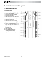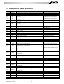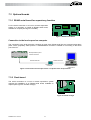
1
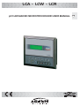
LCA - LCW - LCR
pCO ADVANCED MICROPROCESSOR USER MANUAL
GB
Index
1.
2
General description of the application ......................................................................... 4
1.1
Types of units controlled .................................................................................................................. 4
1.2
Maximum number of compressors................................................................................................... 4
1.3
Types of regulation .......................................................................................................................... 4
1.4
Condensation ................................................................................................................................... 4
1.5
Compressor operating turnover ....................................................................................................... 4
1.6
Defrosting modes (LCA-H model).................................................................................................... 4
1.7
Safety devices on each cooling circuit............................................................................................. 4
1.8
System safety features .................................................................................................................... 4
1.9
Optional accessories........................................................................................................................ 4
Regulation logic........................................................................................................... 5
2.1
2.1.1
2.1.2
2.1.3
2.2
2.2.1
2.2.2
2.2.3
2.2.4
2.2.5
2.3
2.3.1
2.3.2
2.3.3
3
Inlet temperature regulation ............................................................................................................. 5
PROPORTIONAL regulation ....................................................................................................... 5
PROPORTIONAL + INTEGRAL Regulation................................................................................ 5
Setpoint........................................................................................................................................ 5
Compressor times and configuration ............................................................................................... 6
Compressor operation turnover................................................................................................... 6
Minimum compressor “ON” time.................................................................................................. 6
Minimum compressor “OFF” time................................................................................................ 7
Delay between two start-up requests .......................................................................................... 7
Delay between two successive start-ups of the same compressor............................................. 7
Condensation Control ...................................................................................................................... 8
Settings........................................................................................................................................ 8
High pressure alarm .................................................................................................................. 10
Prevent function......................................................................................................................... 10
2.4
Defrost control................................................................................................................................ 10
2.5
Antifreeze regulation ...................................................................................................................... 11
Start-up and configuration ......................................................................................... 13
3.1
Terminal with keyboard and display .............................................................................................. 13
3.2
Display ........................................................................................................................................... 13
3.2.1
Moving around inside the masks ............................................................................................... 13
3.3
Keyboard........................................................................................................................................ 14
3.4
Starting up the unit for the first time ............................................................................................... 15
RG66001134 - Rev.00
2
3.5
4
5
Alarm management ................................................................................................... 16
4.1
Main alarm table ............................................................................................................................ 16
4.2
Alarm history .................................................................................................................................. 17
Menu tree structure ................................................................................................... 18
5.1.1
5.1.2
5.1.3
5.1.4
5.1.5
5.1.6
5.1.7
5.1.8
6
Main menu ................................................................................................................................. 18
Maintenance menu .................................................................................................................... 18
I/O Menu .................................................................................................................................... 20
Clock menu................................................................................................................................ 21
Setpoint Menu............................................................................................................................ 21
User menu ................................................................................................................................. 21
Manufacturer menu.................................................................................................................... 23
Alarm menu ............................................................................................................................... 24
Application setting parameters .................................................................................. 26
6.1
7
General description of menus ........................................................................................................ 15
Table of default settings................................................................................................................. 26
Architecture of the control system ............................................................................. 28
7.1
Microprocessor layout.................................................................................................................... 28
7.2
Description of inputs and outputs................................................................................................... 29
7.3
Optional boards.............................................................................................................................. 31
7.3.1
7.3.2
7.4
RS485 serial board for supervisory function ............................................................................. 31
Clock board................................................................................................................................ 31
Technical data................................................................................................................................ 32
RG66001134 - Rev.00
3
1. General description of the application
The operation of LCA and LCA-H units (heat pump model) is managed by application software installed in
the controller on the unit. The main features of the application program are described below.
1.1 Types of units controlled
The software is designed to control air/water chiller units (LCA model), also models with operation as a heat
pump (LCA-H model).
1.2 Maximum number of compressors
From 1 to 4 hermetic scroll compressors, up to 2 cooling circuits.
1.3 Types of regulation
Proportional regulation or proportional regulation with integral action on the evaporator input temperature.
Possibility of adjusting the setpoint remotely.
1.4 Condensation
Condensation can be carried out in the following modes:
•
on/off based on compressor operation (without pressure transducers);
•
on/off or modulating based on the pressure transducer reading (when high pressure transducers are
enabled);
1.5 Compressor operating turnover
Turnover of all compressors according to a FIFO logic.
Selection of balanced turnover of all compressors according to a FIFO logic.
1.6 Defrosting modes (LCA-H model)
Defrosting can be simultaneous or separated among the circuits.
1.7 Safety devices on each cooling circuit
•
•
•
High pressure (pressure switch).
Low pressure (pressure switch).
Compressor thermal switch.
1.8 System safety features
•
•
•
•
•
Serious alarm (shuts the whole unit down)
Evaporator flow switch (shuts the whole unit down).
Pump thermal switch
Condensation fan thermal switch
Remote on/off input without alarm signalling.
1.9 Optional accessories
•
•
Supervision by means of RS485 serial board.
Alarm history building with clock board.
RG66001134 - Rev.00
4
2 Regulation logic
2.1 Inlet temperature regulation
Inputs used:
•
Evaporator inlet water temperature
Parameters used:
•
Regulation setpoint
•
Proportional band for input temperature regulation.
•
Type of regulation (proportional or proportional + integral)
•
Integration time (if proportional + integral regulation is enabled)
Outputs used:
•
Compressor On/Off
Regulation diagram with two compressors:
2 = C1 e C2 On
1 = C1 On e C2 Off
2
1
0 = C1 e C2 Off
0
Set1-Diff1 Set2-Diff2
Set1
Set2
Inlet water T
Figure 0: Regulation diagram with two compressors
2.1.1 PROPORTIONAL regulation
On the basis of the setpoint entered from the mask (ref. mask M_SETPOINT5, page 21 ), if the secondary
setpoint or the remote setpoint is active, a proportional band is calculated with a width equal to the
differential set from the mask (ref. mask M_USER25, page 21).
Inside this band the positions of the device regulation steps are calculated according to the number of
compressors.
2.1.2 PROPORTIONAL + INTEGRAL Regulation
Proportional + integral regulation uses the same parameters as simple proportional regulation; it calculates
the steps at which the devices are cut in on the basis of the setpoint, the differential and the integration time
set from the mask (ref. mask M_USER20, page 21). The integral action is doubled if the conditions have not
changed after the time set.
2.1.3 Setpoint
Main Setpoint
From the mask M_SETPOINT15 (see page
and winter (LCA-H) operating modes.
) it is possible to set the main setpoint for the summer (LCA)
Secondary Setpoint
From the mask M_MANUF28 (see page 23) it is possible to select the ID 14 digital input configuration for the
management of serious alarms or the secondary setpoint. If secondary setpoint management is selected,
the M_SETPOINT10 (see page 21) is enabled for the setting of the summer and winter setpoints controlled
by the digital input.
RG66001134 - Rev.00
5
With the digital input open, the setpoint entered from the M_SETPOINT5 mask (see page 21) will be used;
with the digital input closed, the secondary setpoint will be used.
An "R" will appear in the upper right corner of the setpoint masks to indicate the activation of the secondary
setpoint.
Remote Setpoint
From the M_USER24 mask (see page 21) it is possible to enable the remote setpoint function that uses an
analog input. The signal will be converted between the minimum and maximum values set from the mask.
The read value will then be added to the setpoint value resulting from the secondary setpoint management.
2.2 Compressor times and configuration
The unit enables the control of hermetic scroll compressors. Mask M_MANUF20 (see 5.1.7 Manufacturer
menu
page 23) is used for configuration purposes; from the mask it is necessary to set the number of compressors
per circuit and the number of circuits.
Most of the operations performed by the pCO1 are conditioned by programmable delays. Some of them
serve to delay the triggering of some alarms or to assure the proper functioning of the compressors, thereby
lengthening their lives and guaranteeing system stability.
2.2.1 Compressor operation turnover
The compressor operation turnover makes it possible to balance the number of hours of operation and the
number of starts-stops of the various compressors. The turnover is carried out according to a FIFO logic,
meaning that the first compressor to start will also be the first to stop. During the initial start-up period this
behaviour may result in big differences between the operating hours of the compressors. However, at full
capacity operation the number of hours will be very similar.
Management without FIFO turnover (with four compressors):
•
Start-up: C1,C2,C3,C4.
•
Stop: C4,C3,C2,C1.
Management with FIFO turnover (with four compressors):
•
Start-up: C1,C2,C3,C4.
•
Stop: C1,C2,C3,C4.
If the turnover function is enabled it is possible to select the balanced turnover , which always follows a
FIFO logic, i.e. the odd devices are activated first and then the even ones:
•
Start-up: C1, C3, C2, C4.
•
Stop: C1, C3, C2, C4.
2.2.2 Minimum compressor “ON” time
(ref. mask M_MANUF40, 5.1.7 see Manufacturer menu
, page 23)
This determines the minimum time (in seconds) the devices must continue running: therefore, once
activated they must stay on for the set length of time.
RG66001134 - Rev.00
6
ON
Start-up
Request
OFF
ON
Device
OFF
Figure 0: Minimum compressor on time
2.2.3 Minimum compressor “OFF” time
(ref. mask M_MANUF40, 5.1.7 see Manufacturer menu
, page 23)
This determines the minimum time the devices must remain off. After they are shut off, the compressors
cannot start up again until the set time has elapsed.
ON
Shut-off
Request
OFF
ON
Device
OFF
Figure 0: Minimum compressor off time
2.2.4 Delay between two start-up requests
(ref. mask M_MANUF45, 5.1.7 see Manufacturer menu
, page 23)
This determines the minimum time that must elapse between two device starts irrespective of the read
measurement or setpoint. This parameter makes it possible to limit the number of starts per hour. If, for
instance, the maximum allowed number of starts per hour is 10, setting a value of 360 seconds will ensure
that this limit is complied with.
ON
Device 1
Start-up
OFF
ON
Device 2
Start-up
OFF
Figure 0: Delay between two start-up requests
2.2.5 Delay between two successive start-ups of the same compressor
(ref. mask M_MANUF45, 5.1.7 see Manufacturer menu
, page 23)
This establishes the minimum time that must elapse between two starts of the same device, irrespective of
the read measurement or the setpoint. This parameter makes it possible to limit the number of starts per
hour. If, for instance, the maximum allowed number of starts per hour is 10, setting a value of 360 seconds
will ensure that this limit is complied with.
RG66001134 - Rev.00
7
ON
Start-up
Request
OFF
ON
Device
OFF
Figure 0: Delay between two successive start-ups of the same compressor
2.3 Condensation Control
Condensation can be regulated according to the following modes
•
on/off based on compressor operation (without pressure transducers);
•
on/off or modulating based on the pressure transducer reading (when high pressure transducers are
enabled);
Inputs used:
•
High pressure probe of first circuit (B5 analog input)
•
High pressure probe of second circuit (B6 analog input)
Parameters used:
•
Condensation control selection: none/pressure
•
Number of fans
•
Type of condensation coil (Single / Separate)
•
Condensation Setpoint
•
Condensation Differential
•
Enabling of prevent function
•
Prevent Setpoint
•
Prevent Differential
•
Delay in device reactivation after triggering of prevent function
•
Output voltage relative to minimum inverter speed
•
Output voltage relative to maximum inverter speed
•
Inverter speed-up time
Outputs used:
•
Fans (NO9 digital output)
•
Fan speed regulation (Y1 analog output)
2.3.1 Settings
For condensation it is necessary to set:
•
the type of regulation by means of the “Abilit.“ (Enable) code in the M_MANUF50 mask (see page 23).
The selection is made between NO / TEMPERATURE for choosing regulation either on the basis of the
compressor status or on the basis of the values read by the pressure transducers;
•
the type of devices used by specifying the “Tipo” (Type) code in the M_MANUF50 mask ( see page 23).
The selection is made between INVERTER / GRADINI (STEPS) for choosing either the modulating or
the ON/OFF type regulation;
•
the number of fans connected if step regulation is selected, by entering a value for “N. Ventilatori” (No.
of fans ) in the M_MANUF55 mask (see page 23);
•
the type of condenser by means of the “Condensatore” (Condenser) code in the M_MANUF55 mask
(see page 23). The selection is made between SINGLE / SEPARATE;
•
the condensation setpoint and the differential, to be entered in the M_MANUF60 mask (see page 23).
The setting generates a proportional band (setpoint / setpoint + differential) from which it calculates the
position of the various fan activation steps or the modulating output value according to the selection
made;
•
the minimum and maximum speeds of the inverter by specifying the “Max.velocità” (Max. Speed),
”Min.velocità” (Min. Speed) codes in the M_MANUF70 mask (see page 23); the proportional action of
the modulating output is calculated within the range of these values;
RG66001134 - Rev.00
8
•
•
•
•
the minimum operating time of the inverter by specifying the “Tempo min ON" (Min. ON Time) code on
the M_MANUF70 mask (see page 23);
enabling of the prevent function by means of the “Abilit." Prevenzione ALTA PRESSIONE (“Enable”
HIGH PRESSURE prevention) code in the M_MANUF80 mask (see page 23). The prevent function will
be executed according to the modes specified below in this section;
the prevent setpoint and differential (ref. M_MANUF80 mask , see page 23);
the delay in compressor restarts after triggering of the prevent function (ref. M_MANUF81 mask page
23);
Condensation on/off based on compressor operation
If NO is selected in the M_MANUF50 mask (see page 23) the fans’ operation will depend only on the
operation of the compressors.
Condensation on/off based on pressure sensor
If PRESSURE is selected in the M_MANUF50 mask (see page 23), the fans’ operation will depend only on
the pressure read by the pressure sensors, according to the selected setpoint and differential band. With
pressure values lower or equal to the setpoint all fans will be turned off; with pressure values higher than the
setpoint + differential band, all fans will be turned on. It will be possible to select the condensation function
either with a single coil or separate coil. In the case of single coil condensation, the fans will be controlled by
the highest pressure; with separate coil condensation each pressure sensor will control its respective fan.
Modulating condensation based on pressure sensor
If this type of condensation is chosen, the fans will be controlled in a manner proportional to the readings of
the pressure sensor. It will be possible to select the condensation function either with a single or separate
coil. In the case of a single coil, the inverter will be controlled by the highest pressure; with a separate coil
each pressure sensor will control its respective inverter. The graph below shows fan operation after the
setpoint and the differential band have been set.
Fan power
supply
10V
0V
Differential band
Setpoint
Setpoint + diff.
High pressure
probe (bar)
Figure 0: Modulating condensation based on pressure sensor
If the minimum fan speed is assigned to a power supply value higher than 0V (the graph shows a case
where the minimum speed has been assigned to 3V) a 1 bar hysteresis (default) is applied in order to avoid
repeated start-ups and stops.
RG66001134 - Rev.00
9
Fan power
supply
10V
3V
0V
Differential band
Setpoint -1
Setpoint
Setpoint + diff.
High pressure
probe (bar)
Figure 0: Modulating condensation with 1 bar Hysteresis
2.3.2 High pressure alarm
If the pressure value exceeds the high pressure alarm setpoint selected in the M_MANUF85 mask (see
page 23) an alarm will be signalled and the circuit concerned will be deactivated. The alarm will turn off
when the pressure drops below the setpoint – differential value.
2.3.3 Prevent function
Selecting this function requires access to a factory-set password. It serves to prevent circuits from being
blocked due to the triggering of the high pressure alarm. It can be set only on units having two compressors
per circuit.
Setpoint and differential values must be selected from the M_MANUF80 mask (see page 23 ). The prevent
function shuts off the compressors, thereby dividing the power supplied to the cooling circuit. When the
condensation pressure exceeds the prevent function activation value (setpoint), the function is triggered and
remains active until the value detected goes below the prevent function deactivation value (setpoint –
differential). At this point a delay is activated (settable from the M_MANUF81 mask on page 23) which
lengthens the prevent action, thus delaying any restart of the compressors.
2.4 Defrost control
Inputs used:
•
High pressure probe of first circuit (B5 analog input)
•
High pressure probe of second circuit (B6 analog input)
Parameters used:
•
Inputs used for defrosting
•
Defrosting modes (simultaneous / separate)
•
Start defrost setting
•
End defrost setting
•
Defrost delay time
•
Maximum defrost time
•
Drip time
•
Reverse cycle with compressors off (No / Input / Output / Input-Output)
Outputs used:
•
Compressor 1
•
Compressor 2
•
Compressor 3
•
Compressor 4
•
Reversing solenoid valve – cycle 1
•
Reversing solenoid valve – cycle 2
•
Fans
RG66001134 - Rev.00
10
The defrosting function requires the setting of some parameters protected by a factory-set password (ref.
M_MANUF130 mask page 23), i.e.:
•
PRESSURE defrosting probe;
•
Defrosting mode (SIMULTANEOUS / SEPARATE);
•
Cooling cycle reverse with compressors turned off (NO / INPUT /OUTPUT / INPUT-OUTPUT);
as well as some parameters protected by a user password (ref. M_USER50 / 55 mask – see page 23), i.e.:
•
start/end defrost threshold;
•
defrost activation delay time;
•
maximum defrost time;
•
drip time at the end of defrosting cycle;
Defrosting of one circuit under pressure control:
The defrosting cycle starts when the coil temperature/pressure remains below the start defrost threshold for
a total time (t1+t2+t3) equal to the defrost delay time and if at least one compressor of the circuit concerned
is on.
•
compressors are or are not turned off according to the selection made from the mask and the cooling
cycle is reversed by means of the 4-way valves.
•
the fans are forced into the OFF mode.
The circuit terminates the defrosting cycle when the threshold is exceeded, i.e. when the
temperature/pressure value exceeds the end defrost setpoint or when the maximum time set from the mask
has elapsed if the temperature/pressure value has not exceeded the end defrost setpoint.
Pressure
Fine Set
Set
t1
t2
t3
Defrosting
cycle
Time
Figure 0: Defrosting cycle
Simultaneous defrosting mode
Even if only one circuit requires defrosting, all circuits are forced into the defrosting mode. Circuits not
requiring defrosting (temperature/pressure higher than the end defrost threshold) stop and remain on standby. As soon as the defrosting cycle has terminated, all the compressors can start up again in the heat pump
mode.
Separate defrosting mode
In this defrosting mode each cooling circuit undergoes a defrosting cycle separately. The first circuit
requiring defrosting starts a defrosting cycle, whereas the other circuits remain on standby until the first
circuit has completed its defrosting cycle, even if they too require defrosting. When the defrosting cycle of
the first circuit is finished, the following circuit will be defrosted, while the other circuits wait their turn.
2.5 Antifreeze regulation
Inputs used
•
Evaporator outlet water temperature probe.
Parameters used:
•
Enabling of outlet line probe;
•
Antifreeze alarm setpoint;
RG66001134 - Rev.00
11
•
Antifreeze alarm differential;
Outputs used:
•
Antifreeze alarm;
Each pCO1 unit can manage antifreeze regulation provided that the outlet temperature probe is connected
and enabled.
Alarm status
Alarm ON
Alarm OFF
Antifreeze
differential
Evaporator outlet temperature
Antifreeze Setpoint + diff. Band setpoint
Figure 0: Antifreeze regulation
RG66001134 - Rev.00
12
3 Start-up and configuration
3.1 Terminal with keyboard and display
Figure 0: Terminal
The user terminal is shown in the picture. It consists of a 4 line x 20 column LCD, keyboard and LEDs
controlled by a microprocessor: from the terminal the user can set the control parameters (setpoint,
differential band, alarm thresholds, etc.) and perform fundamental operations.
The following main operations can be performed via the terminal:
• initial machine configuration;
• modification of main operating parameters;
• display of machine status and of all measured data;
• display of the alarms detected and a 'buzzer' (that can be disabled);
The terminal and the pCO1 controller are connected via a 6-way telephone cable. This connection is not
essential for standard controller operation.
3.2 Display
The display used is of the 4 line x 20 column LCD type. The data and information regarding operation
alternate as successive windows called masks. It is possible to move around inside the masks using the
terminal keys as described below:
3.2.1 Moving around inside the masks
╔════════════════════╗
║x
Line0
║
║Home
Line1
║
║
Line2
║
║
Line3
║
╚════════════════════╝
If the cursor is positioned in the top left-hand corner (Home) pressing the
keys allows the user to
access the successive masks associated with the selected branch. If a mask includes fields for setting
values, pressing the ENTER key will cause the cursor to move into these fields. Once a parameter setting
keys. Once the
field is reached it is possible to change its value, within the set limits, by pressing the
desired value has been set, pressing the ENTER key again will store it in the memory.
RG66001134 - Rev.00
13
3.3 Keyboard
Key 1
↓
Key 2
↓
Key 3
↓
Key 4
↓
↑
Key 8
↑
Key 9
↑
Key 10
↑
Key 11
Key 5
↓
↑
Key 12
Key 6
↓
↑
Key 13
↑
Key 14
Key 7
↓
↑
Key 15:
Key 1: Accesses the mask displaying the fundamental machine data and status.
Key 2: Accesses device maintenance data (hours of service of a device and hour meter reset, alarm history,
manual operating procedure).
Key 3: Function not active.
Key 4: Accesses the masks displaying digital and analog input/output statuses.
Key 5: Accesses the clock programming mask (if a clock board is included).
Key 6: Accesses the setpoint display / setting masks.
Key 7: Accesses the user parameter programming masks (thresholds, delays etc.).
Key 1 + Key 7: By pressing these keys at the same time the user accesses the machine configuration
(number of devices connected to the pCO1, programming of the full scale values, etc.).
Key 8: Displays data concerning the software used.
Key 9: For selecting the winter mode (LCA-H model, not available on the LCA model).
Key 10: For selecting the summer mode (LCA-H model, this mode is always active on the LCA model).
Key 11: This key allows the unit to be switched on and off. The green LED illuminating the key indicates the
unit status.
Key 12: This key is used for displaying alarms, resetting them manually and silencing the buzzer. If the key
is lit (red LED) it means that at least one alarm has been detected. Pressing the key once will silence the
buzzer and cause a mask to appear which describes the alarm that is active. Pressing a second time will
reset the alarm signalling function.
Key 13: this key enables the setting of control parameters as well as movement from one mask to another
(not backlit).
Key 14: this key enables the setting of control parameters as well as movement from one mask to another
(not backlit).
Key 15: used for moving the cursor inside the masks and saving parameter settings. The key is constantly
backlit (yellow light) to indicate that the power supply is on.
NOTE: The LEDs alongside each key come on when the respective function is activated.
RG66001134 - Rev.00
14
3.4 Starting up the unit for the first time
When the microprocessor is connected to the power supply, the main menu will be displayed (M_Main). It
contains the following information:
•
•
•
•
M_Main
╔════════════════════╗
║00 00
00 00 00║
║Inlet water
00.0°C║
║Outlet water 00.0°C║
║ON
║
╚════════════════════╝
current date and time;
evaporator inlet water temperature;
evaporator outlet water temperature;
unit status;
3.5 General description of menus
General description of the menus featured in the application; all the masks are shown and described in the
chapter 5
Main menu
The main menu is displayed when the unit is started up and consists of the two masks described in the
section 3.4 Starting up the unit for the first time
Maintenance menu
The maintenance menu can be accessed by pressing key 2. It shows the compressor and pump hour
meters as well as the alarm history if a clock board has been installed.
If the maintenance password is entered (given to maintenance personnel directly by Galletti S.p.a) it will be
possible to set the device hour meter alarm thresholds, clear the hour meter, set the probes, set the pump
type and turnover time and enable the buzzer.
I/O Menu
The I/O menu can be accessed by pressing key 4 and shows the system’s inputs and outputs.
Clock menu
The clock menu can be accessed by pressing key 5 and contains the time and date configuration.
Setpoint Menu
The Setpoint menu can be accessed by pressing key 6 and allows management of fixed and variable
setpoints.
User menu
The User menu can be accessed by pressing key 7 and contains the configuration of user parameters. It is
password protected.
Manufacturer menu
The Manufacturer menu can be accessed by pressing key 1 + key 7 together and contains the configuration
of factory-set parameters. It is password protected.
Alarm menu
The Alarm menu can be accessed by pressing key 12 and gives information about the alarms that have
been triggered.
RG66001134 - Rev.00
15
4 Alarm management
The alarms are divided into three categories:
1. Warnings only (with display of warning message and buzzer or display of warning message, buzzer
and alarm relay)
2. Circuit alarms (with deactivation of the circuit concerned, display of alarm message, buzzer and
alarm relay);
3. Serious alarms (with shut down of the whole system, display of alarm message, buzzer and alarm
relay).
Warnings
•
Unit maintenance warning;
•
Compressor maintenance warning;
•
Clock board failure or disconnection;
Circuit alarms
•
High pressure/pressure switch alarm: immediate shut down of the compressor and manual resetting
•
Low pressure alarm with automatic/manual resetting (see description of its operation)
•
Compressor thermal switch alarm with immediate shut down of the compressor and manual resetting;
•
Fan thermal switch alarm, with fan stop and manual resetting.
Serious Alarms
•
lack of water flow digital input alarm, delayed at start-up and at full capacity operation;
•
evaporator antifreeze alarm, evaporator outlet probe function with activation setpoint and reset
differential, with manual resetting
•
serious alarm from digital input. Immediate shut down of the unit and manual resetting.
The alarms are reset manually by pressing the alarm key twice.
4.1 Main alarm table
Alarm Description
Serious alarm
Antifreeze alarm
Thermal switch-Pump 1
Thermal switch-Pump 2
Evaporator flow switch
Low pressure Press. switch
C1
Low pressure Press. switch
C2
High pressure Press. switch
C1
High pressure Press. switch
C2
Fan thermal switch 1
Fan thermal switch 2
Probe failure B1
Probe failure B2
Probe failure B3
Probe failure B4
Probe failure B5
RG66001134 - Rev.00
Compr.
Off
*
*
*
*
*
Fan
Off
*
*
*
*
*
Pump
Off
*
Reset
Auto/Man
Man.
Man.
Man.
Man.
Man.
No
No
No
No
settable
*
Man.
settable
*
Man.
no
Auto.
Auto.
Auto.
Auto.
Auto.
60 sec.
60 sec.
60 sec.
60 sec.
60 sec.
*
*
16
System
Off
*
*
*
*
Delay
Probe failure B6
Maint. Pump 1
Maint. Pump 2
Maint. Compressor 1
Maint. Compressor 2
Maint. Compressor 3
Maint. Compressor 4
Phase direction
*
*
*
*
Auto.
Man.
Man.
Man.
Man.
Man.
Man.
Man.
60 sec.
-
4.2 Alarm history
The unit has an alarm history function. To activate this function it is necessary to install the optional clock
board, provided with 32k memory, and enable its use from the mask (ref. mask M_MANUF27 5.1.7 see
Manufacturer menu
, page 23)
Alarms are memorised according to priorities decided at the programming stage. Each alarm has been
attributed a priority code (the lower the code, the higher the priority); in this way if two alarms with different
priorities are tripped at the same time, only the alarm with the lower code is stored (ref. 5.1.8 Alarm menu
).
In addition to the alarm code, the function stores the date and time, evaporator inlet and outlet temperatures,
setpoint and band used at the moment the alarm is activated (ref. mask M_MAINT17 see page ).
M_Maint17
╔════════════════════╗
║History alarm
0000║
║AL000 00:00 00/00/00║
║Set 00.0 Band 00.0║
║T.In 00.0 T.out 00.0║
╚════════════════════╝
A maximum number of 1600 alarms can be stored. After this limit is reached memorisation will again start
from the beginning, i.e. the oldest alarm will be overwritten with the new data.
RG66001134 - Rev.00
17
5 Menu tree structure
5.1.1 Main menu
M_Main
╔════════════════════╗
║00 00
00 00 00║
║Inlet water
00.0°C║
║Outlet water 00.0°C║
║ON
║
╚════════════════════╝
The main information regarding the chiller’s operation is displayed here. If the
(optional) clock board has been installed, the current date and time will also be
displayed
5.1.2 Maintenance menu
M_Maint5
╔════════════════════╗
║Pump 1
║
║hour meters
║
║
║
║Hours
000000║
╚════════════════════╝
M_Maint6
╔════════════════════╗
║Pump 2
║
║hour meters
║
║
║
║Hours
000000║
╚════════════════════╝
Pressing the MAINTENANCE key provides access to these masks, which
display the number of hours of work performed by each device. These values
will be stored in the flash memory of the pCO1 board; data are recorded at
three-hour intervals.
This function is provided whether or not a clock board is installed on the pCO1.
If the number of working hours of a device equals the set threshold, the
relative alarm is triggered.
║
M_Maint10
╔════════════════════╗
║Hour meters
║
║
║
║Compressor 1 000000║
║Compressor 2 000000║
╚════════════════════╝
M_Maint15
╔════════════════════╗
║Hour meters
║
║
║
║Compressor 3 000000║
║Compressor 4 000000║
╚════════════════════╝
M_Maint17
╔════════════════════╗
║History alarm
0000║
║AL000 00:00 00/00/00║
║Set 00.0 Band 00.0║
║T.In 00.0 T.out 00.0║
╚════════════════════╝
M_Pw_Maint
╔════════════════════╗
║Insert
║
║maintenance password║
║
║
║
0000 ║
╚════════════════════╝
M_Maint20
╔════════════════════╗
║Pump 1 hour meter ║
║
║
║threshold
000x1000║
║Req.reset
N 000000║
╚════════════════════╝
RG66001134 - Rev.00
This is the alarm history mask.
The maintenance password is required for viewing the following masks. The
password is only available on request.
In these masks it is possible to modify the value of the device maintenance
alarm threshold and reset the hour meter of each device after it has undergone
maintenance
18
M_Maint21
╔════════════════════╗
║Pump 2 hour meter ║
║
║
║threshold
000x1000║
║Req.reset
N 000000║
╚════════════════════╝
M_Maint25
╔════════════════════╗
║Compressor 1
║
║hour meter
║
║Threshold
000x1000║
║Req.reset
N 000000║
╚════════════════════╝
M_Maint30
╔════════════════════╗
║Compressor 2
║
║hour meter
║
║Threshold
000x1000║
║Req.reset
N 000000║
╚════════════════════╝
M_Maint35
╔════════════════════╗
║Compressor 3
║
║hour meter
║
║Threshold
000x1000║
║Req.reset
N 000000║
╚════════════════════╝
M_Maint40
╔════════════════════╗
║Compressor 4
║
║hour meter
║
║Threshold
000x1000║
║Req.reset
N 000000║
╚════════════════════╝
M_Maint45
╔════════════════════╗
║Filters config.
║
║Enable
N ║
║Anal. delay time 0s║
║Dig. delay time
0s║
╚════════════════════╝
M_Maint50
╔════════════════════╗
║Inputs probes offset║
║B1: 0.0
B2: 0.0 ║
║B3: 0.0
B4: 0.0 ║
║B5: 0.0
B6: 0.0 ║
╚════════════════════╝
From this mask it is possible to enable the software filters applied on analog
inputs. The detected input value is transmitted to the control if it maintains the
value for a time equal to or greater than the time set.
Here it is possible to set probe offset values to be added to or subtracted from
readings. (See 17 flap for installation of clock board (optional) .
)
M_Maint60
╔════════════════════╗
║Pump sequence type ║
║
║
║
║
║AUTOMATIC
║
╚════════════════════╝
M_Maint65
╔════════════════════╗
║Pump sequence time ║
║
║
║
║
║
000 hours║
╚════════════════════╝
RG66001134 - Rev.00
19
M_Maint70
╔════════════════════╗
║Pump sequence
║
║selection
║
║
║
║SEQUENCE 1
║
╚════════════════════╝
M_Maint75
╔════════════════════╗
║Erase historical
║
║memory board
║
║
N ║
║
║
╚════════════════════╝
This mask only appears if the clock board has been configured and the unit is
off. Selecting S activates the procedure of erasing all the historical data.
During this operation, a stand-by message will appear on the last line of the
mask and no other operation will be possible until erasure is complete.
M_Maint100
╔════════════════════╗
║Insert another
║
║maintenance
║
║password
║
║
0000 ║
╚════════════════════╝
5.1.3 I/O Menu
This set of masks provides a complete display of the statuses of the analog and digital inputs and outputs
connected to the microprocessor.
M_InOut10
╔════════════════════╗
║Digital inputs
║
║CCCCCCCCCCCC
║
║Digital outputs
║
║OOOOOOOOOOOOO
║
╚════════════════════╝
M_InOut15
╔════════════════════╗
║Analog inputs
║
║
║
║B1:
00.0°C ║
║B2:
00.0°C ║
╚════════════════════╝
M_InOut20
╔════════════════════╗
║Analog inputs
║
║
║
║B3:
00.0°C ║
║B4:
00.0°C ║
╚════════════════════╝
M_InOut25
╔════════════════════╗
║Analog inputs
║
║B5:
00.0bar║
║B6:
00.0bar║
║B7:
00.0°C ║
╚════════════════════╝
M_InOut35
╔════════════════════╗
║Analog outputs
║
║
║
║Y0:
00.0V║
║Y1:
00.0V║
╚════════════════════╝
RG66001134 - Rev.00
20
5.1.4 Clock menu
M_Clock5
╔════════════════════╗
║
║
║
Clock not
║
║
installed
║
║
║
╚════════════════════╝
M_Clock10
╔════════════════════╗
║Clock configuration ║
║
║
║Time
00:00║
║Date
00/00/00║
╚════════════════════╝
When the clock key is pressed, this mask will be displayed if the clock board
has not been configured in the manufacturer branch (ref. mask M_MANUF27
When the clock key is pressed, if the clock board has been configured in the
manufacturer branch (ref. mask M_MANUF27) this mask is displayed; from
here it is possible to set the current date and time.
5.1.5 Setpoint Menu
M_Setpoint1
╔════════════════════╗
║Actual setpoint
║
║
║
║
00.0°C║
║
║
╚════════════════════╝
By pressing the SET key it is possible to access the following masks in order
to view the summer and winter setpoints and active differentials
M_Setpoint5
╔════════════════════╗
║Summer setpoint
║
║
00.0°C║
║Winter setpoint
║
║
00.0°C║
╚════════════════════╝
M_Setpoint10
╔════════════════════╗
║Second summer
║
║setpoint
00.0°C║
║Second winter
║
║setpoint
00.0°C║
╚════════════════════╝
5.1.6 User menu
User menu access is password protected.
User password: 100
M_User5
╔════════════════════╗
║Summer temperature ║
║setpoint limits
║
║Low
00.0°C║
║High
00.0°C║
╚════════════════════╝
In these masks it is possible to select the minimum and maximum summer and
winter setpoint values that may be set.
M_User15
╔════════════════════╗
║Winter temperature ║
║setpoint limits
║
║Low
00.0°C║
║High
00.0°C║
╚════════════════════╝
M_User17
╔════════════════════╗
║Regulat. tmperature ║
║
║
║Type
INLET
║
║
║
╚════════════════════╝
RG66001134 - Rev.00
21
M_User20
╔════════════════════╗
║Inlet regulation
║
║
║
║Type
PROP.
║
║Integration t. 0000s║
╚════════════════════╝
If inlet regulation is selected, it is possible to choose whether to adopt a
proportional or a proportional + integral type of regulation. In the latter case an
integration time will also be set.
M_User22
╔════════════════════╗
║Outlet regulation
║
║
║
║Time on
0000s║
║Time off
0000s║
╚════════════════════╝
M_User23
╔════════════════════╗
║Outlet regulation
║
║force off
║
║Summer
00.0°C║
║Winter
00.0°C║
╚════════════════════╝
M_User24
╔════════════════════╗
║External setpoint
║
║Enable
N ║
║Min.
00.0°C║
║Max.
00.0°C║
╚════════════════════╝
M_User25
╔════════════════════╗
║Temperature band
║
║
00.0°C║
║
║
║
║
╚════════════════════╝
M_User30
╔════════════════════╗
║Time between
║
║main pump/fan
║
║and compressors
║
║start
000s║
╚════════════════════╝
M_User35
╔════════════════════╗
║Delay on switching ║
║the main
║
║pump/fan off
║
║
000s║
╚════════════════════╝
M_User40
╔════════════════════╗
║Digital input remote║
║on / off
N ║
║Digital input remote║
║Summer / Winter
N ║
╚════════════════════╝
M_User42
╔════════════════════╗
║Supervisory remote ║
║on / off
N ║
║Supervisory remote ║
║Summer / Winter
N ║
╚════════════════════╝
RG66001134 - Rev.00
This mask enables the temperature regulation band to be set; on the basis of
this value, according to the type of regulation selected, the proportional band
or neutral zone will be calculated.
In this mask it is possible to set the minimum delay between the pump start
and compressor start
In this mask the pump shut off delay can be set.
In this mask it is possible to set/enable the digital input remote on/off
command. The summer/winter switching is not available.
In this mask it is possible to set/enable the remote on/off command from the
supervisory system. The summer/winter function is not available.
22
M_User50
╔════════════════════╗
║Defrost parameters ║
║
║
║Start
00.0°C ║
║Stop
00.0°C ║
╚════════════════════╝
In this mask it is possible to set the defrost regulation parameters.
M_User55
╔════════════════════╗
║Defrost parameters ║
║Delay time
00000s║
║Maximum time 00000s║
║Drip time
000s║
╚════════════════════╝
M_User60
╔════════════════════╗
║Insert another
║
║user password
║
║
║
║
0000 ║
╚════════════════════╝
Here it is possible to change the user access password.
5.1.7 Manufacturer menu
User menu access is password protected. The password is only available on request.
M_Manuf5
╔════════════════════╗
║Unit config.
00 ║
║AIR/WATER
║
║CHILLER
║
║SEMIHERMETIC COMPS. ║
╚════════════════════╝
M_Manuf6
╔════════════════════╗
║Heatpump enable:
N║
║
║
║
║
║
║
╚════════════════════╝
M_Manuf7
╔════════════════════╗
║Evap./condenser
║
║flow alarm and
║
║serious alarm
║
║Enable
N ║
╚════════════════════╝
M_Manuf10
╔════════════════════╗
║Probes enable
║
║B1: N B2: N B3: N ║
║B4: N B5: N B6: N ║
║B7: N
║
╚════════════════════╝
M_Manuf15
╔════════════════════╗
║Pressure probe conf.║
║
║
║ 4mA
000.0bar║
║20mA
000.0bar║
╚════════════════════╝
M_Manuf20
╔════════════════════╗
║Compressors config. ║
║
║
║Circuit Nr.
0 ║
║Comp. per circuit 0 ║
╚════════════════════╝
M_Manuf25
╔════════════════════╗
║Compressors config. ║
║PW time
000-ms║
║Comp. Turnover
N ║
║Balanced turnover N║
╚════════════════════╝
M_Manuf27
╔════════════════════╗
║Clock board 32k
║
║
║
║Enable
N ║
║
║
╚════════════════════╝
M_Manuf28
╔════════════════════╗
║Digital input 1
║
║configuration
║
║
║
║SERIOUS ALARM
║
╚════════════════════╝
M_Manuf40
╔════════════════════╗
║Minimum compressors ║
║power-on time 0000s║
║Minimum compressors ║
║power-off time 0000s║
╚════════════════════╝
M_Manuf45
╔════════════════════╗
║Min time betw. diff.║
║comp. starts
0000s║
║Min time betw. same ║
║comp. starts
0000s║
╚════════════════════╝
M_Manuf50
╔════════════════════╗
║Condensation
║
║
║
║Enable :NONE
║
║Type
:INVERTER
║
╚════════════════════╝
M_Manuf55
╔════════════════════╗
║Condensation
║
║
║
║Fans Nr.
0 ║
║Condenser
SINGLE ║
╚════════════════════╝
M_Manuf60
╔════════════════════╗
║Condensation
║
║
║
║Setpoint
000.0---║
║Diff.
000.0---║
╚════════════════════╝
M_Manuf70
╔════════════════════╗
║Inverter
║
║Max. speed
00.0V║
║Min. speed
00.0V║
║Speed up time
000s║
╚════════════════════╝
RG66001134 - Rev.00
23
M_Manuf80
╔════════════════════╗
║Prevent
║
║
N ║
║Setpoint
00.0---║
║Diff.
00.0---║
╚════════════════════╝
M_Manuf81
╔════════════════════╗
║Prevent
║
║
║
║Devices exit
║
║delay
000 s║
╚════════════════════╝
M_Manuf85
╔════════════════════╗
║Transducers high
║
║pressure alarm
║
║Setpoint
00.0bar║
║Diff.
00.0bar║
╚════════════════════╝
M_Manuf90
╔════════════════════╗
║Low pressure alarm ║
║
║
║Startup delay
000s║
║Run delay
000s║
╚════════════════════╝
M_Manuf91
╔════════════════════╗
║Low pressure alarm ║
║Events Nr.
0 ║
║Period
0000s║
║Timeout start
000s║
╚════════════════════╝
M_Manuf100
╔════════════════════╗
║Antifreeze alarm
║
║
║
║Setpoint
00.0°C║
║Diff.
00.0°C║
╚════════════════════╝
M_Manuf105
╔════════════════════╗
║Antifreeze heater
║
║
║
║Setpoint
00.0°C║
║Diff.
00.0°C║
╚════════════════════╝
M_Manuf110
╔════════════════════╗
║Evaporat. flow alarm║
║
║
║Startup delay
000s║
║Run delay
000s║
╚════════════════════╝
M_Manuf125
╔════════════════════╗
║Reversing valve
║
║logic
║
║
║
║
N.C.║
╚════════════════════╝
M_Manuf130
╔════════════════════╗
║Defrost config.
║
║Probe TEMPERATURE ║
║Type
SIMULTANEOUS ║
║Off Comp:
NO║
╚════════════════════╝
M_Manuf132
╔════════════════════╗
║Supervisory System ║
║Communication speed:║
║1200 (RS485/RS422) ║
║Indentificat.Nr.:000║
╚════════════════════╝
M_Manuf135
╔════════════════════╗
║Reset all parameters║
║to default values N║
║
║
║
║
╚════════════════════╝
M_Manuf190
╔════════════════════╗
║Insert another
║
║manufacturer
║
║password
║
║
0000 ║
╚════════════════════╝
5.1.8 Alarm menu
Each mask gives information about a specific alarm situation. The activation of the masks is accompanied
by the sounding of the buzzer and tripping of the general alarm signalling relay. By pressing the ALARM key
keys. Pressing the
once the user can access the first active mask and then scroll all alarms using the
ALARM a second time will clear the alarm message. Each mask shows the code used in the alarm history to
identify the particular event (ref. 4.2 Alarm history
page 17)
M_Alarm00
╔════════════════════╗
║
║
║
No alarms
║
║
detected
║
║
║
╚════════════════════╝
M_Alarm5
╔════════════════════╗
║AL:002
║
║
Freeze alarm
║
║
║
║
║
╚════════════════════╝
M_Alarm10
╔════════════════════╗
║AL:016
║
║
Compressor 1/2
║
║
overload
║
║
║
╚════════════════════╝
M_Alarm20
╔════════════════════╗
║AL:018
║
║
Compressor 3/4
║
║
overload
║
║
║
╚════════════════════╝
M_Alarm30
╔════════════════════╗
║AL:005
║
║
Evaporator flow ║
║
alarm
║
║
║
╚════════════════════╝
M_Alarm40
╔════════════════════╗
║AL:012
║
║
High pressure
║
║
circuit 1
║
║
║
╚════════════════════╝
RG66001134 - Rev.00
24
M_Alarm45
╔════════════════════╗
║AL:013
║
║
High pressure
║
║
circuit 2
║
║
║
╚════════════════════╝
M_Alarm60
╔════════════════════╗
║AL:010
║
║ Low pressure alarm ║
║
circuit 1
║
║
║
╚════════════════════╝
M_Alarm65
╔════════════════════╗
║AL:011
║
║ Low pressure alarm ║
║
circuit 2
║
║
║
╚════════════════════╝
M_Alarm70
╔════════════════════╗
║AL:023
║
║
High pressure
║
║ alarm transducer 1 ║
║
║
╚════════════════════╝
M_Alarm75
╔════════════════════╗
║AL:024
║
║
High pressure
║
║ alarm transducer 2 ║
║
║
╚════════════════════╝
M_Alarm80
╔════════════════════╗
║AL:001
║
║
Serious alarm
║
║ by digital input ║
║
║
╚════════════════════╝
M_Alarm210
╔════════════════════╗
║AL:025
║
║
Pump 1
║
║
overload
║
║
║
╚════════════════════╝
M_Alarm220
╔════════════════════╗
║AL:026
║
║
Pump 2
║
║
overload
║
║
║
╚════════════════════╝
M_Alarm100
╔════════════════════╗
║AL:049
║
║
Main fan
║
║
overload
║
║
║
╚════════════════════╝
M_Alarm130
╔════════════════════╗
║AL:030
║
║
B1 probe fault
║
║ or not connected ║
║
║
╚════════════════════╝
M_Alarm135
╔════════════════════╗
║AL:031
║
║
B2 probe fault
║
║ or not connected ║
║
║
╚════════════════════╝
M_Alarm140
╔════════════════════╗
║AL:032
║
║
B3 probe fault
║
║ or not connected ║
║
║
╚════════════════════╝
M_Alarm145
╔════════════════════╗
║AL:033
║
║
B4 probe fault
║
║ or not connected ║
║
║
╚════════════════════╝
M_Alarm150
╔════════════════════╗
║AL:034
║
║
B5 probe fault
║
║ or not connected ║
║
║
╚════════════════════╝
M_Alarm155
╔════════════════════╗
║AL:035
║
║
B6 probe fault
║
║ or not connected ║
║
║
╚════════════════════╝
M_Alarm170
╔════════════════════╗
║AL:040
║
║
Main fan/pump
║
║
maintenance
║
║
║
╚════════════════════╝
M_Alarm175
╔════════════════════╗
║AL:041
║
║
Compressor 1
║
║
maintenance
║
║
║
╚════════════════════╝
M_Alarm180
╔════════════════════╗
║AL:042
║
║
Compressor 2
║
║
║
maintenance
║
║
╚════════════════════╝
M_Alarm185
╔════════════════════╗
║AL:043
║
║
Compressor 3
║
║
maintenance
║
║
║
╚════════════════════╝
M_Alarm190
╔════════════════════╗
║AL:044
║
║
Compressor 4
║
║
maintenance
║
║
║
╚════════════════════╝
M_Alarm195
╔════════════════════╗
║AL:050
║
║ 32K clock board
║
║
fault or not
║
║
connected
║
╚════════════════════╝
RG66001134 - Rev.00
25
6 Application setting parameters
6.1 Table of default settings
Category
Probe management
Inputs/Outputs
management
Circuit configuration
Setting parameters
Main pump/fan
management
Compressor parameters
RG66001134 - Rev.00
Description
Enable probe 1
Enable probe 2
Enable probe 3
Enable probe 4
Enable probe 5
Enable probe 6
Enable probe 7
Enable probe 8
Setting of probe 1
Setting of probe 2
Setting of probe 3
Setting of probe 4
Setting of probe 5
Setting of probe 6
Pressure probe minimum value 0V
Pressure probe maximum value 5V
Enable compressor 1
Enable compressor 2
Enable compressor 3
Enable compressor 4
Enable remote on/off by digital input
Configuration of digital input 14
Enable filters
Digital filter delay
Unit configuration
No. of compressors
Summer setpoint
Winter setpoint
Secondary summer setpoint
Secondary winter setpoint
Summer minimum setpoint limit
Summer maximum setpoint limit
Winter minimum setpoint limit
Winter maximum setpoint limit
Temperature regulation band
Temperature regulation type
Inlet temperature regulation
Integration time
Cycle reversing valve logic
Main pump/fan turn-off delay
Delay time between starts of pump/fan
compressors
Pump sequence time
Pump maintenance type
Enable turnover
Enable balanced turnover
Minimum compressor run time
Minimum compressor stop time
Minimum time between start ups of different
compressors
26
Default
Y
Y
Y
N
S
S
N
N
0
0
0
0
0
0
0 bar
30 bar
Y
Y
Y
Y
N
Serious alarm
N
2s
02
1
12 ºC
40°C
12 ºC
40°C
7 ºC
17 ºC
40 ºC
50 ºC
4 ºC
inlet
proportional
600 s
N.C.
5s
5s
24 h
AUTO
Y
N
60 s
360 s
10 s
Condensation regulation
Defrosting management
Remote setpoint
management
Hour meter management
Antifreeze management
Flow switch management
Transducer high pressure
alarm management
Low pressure alarm
management
Supervisor management
Password
RG66001134 - Rev.00
Minimum time between start ups of same
compressor
Condensation setpoint
Condensation differential
Type of condenser
Type of condensation regulation
Number of condensation fans
Type of device cut in
Enable high pressure prevent
Prevent setpoint
Prevent differential
Maximum fan speed inverter output voltage
Minimum fan speed inverter output voltage
Minimum inverter start up time
Delay in device start up after triggering of
prevent function
Type
Probe
Defrost start threshold
Defrost end threshold
Defrost activation delay
Maximum defrosting time
Compressor shut down for defrosting
Drip time
Enable remote setpoint
Remote minimum setpoint limit
Remote maximum setpoint limit
Hour threshold – pump 1
Hour threshold – pump 2
Hour threshold – compressor 1
Hour threshold – compressor 2
Hour threshold – compressor 3
Hour threshold – compressor 4
Antifreeze alarm setpoint
Antifreeze alarm differential
Evaporator flow switch alarm delay at start up
Evaporator flow switch alarm delay at full
capacity operation
High pressure alarm setpoint
High pressure alarm differential
Low pressure alarm delay at start up
Low pressure alarm delay at full capacity
operation
Number of low pressure alarm activations
Alarm activation sampling period
Timeout
Enable supervisor summer/winter selection
Enable supervisor on/off function
Baud rate
Ident
Maintenance password
User password
Manufacturer password
27
450 s
14 bar
7 bar
single
pressure
1
inverter
Y
26.5 bars
2 bars
10 V
0V
0s
10 s
Simultaneous
Pressure
2 bars
12 bars
1800 s
300 s
NO
10 s
N
0 ºC
5 ºC
10000 h
10000 h
10000 h
10000 h
10000 h
10000 h
4 ºC
1 ºC
20 s
10 s
27 bars
2 bars
120 s
0s
3
3600 s
20 s
N
N
19200 bps
1
100
-
7 Architecture of the control system
7.1 Microprocessor layout
Connector description
1.
2.
3.
4.
5.
6.
7.
8.
9.
10.
11.
12.
13.
14.
15.
16.
17.
connector to the power supply [G(+), G0(-)];
fuse 250 Vac, 2A delayed (T2 A);
universal analog inputs NTC, 0/1 V, 0/5 V,
0/20 mA, 4/20 mA;
passive analog inputs NTC and ON/OFF
passive analog inputs NTC
Yellow LED indicating power supply on and
3 indicator LEDs;
0/10 V analogue outputs and PWM phasecut outputs;
digital inputs at 24 Vac/Vdc;
digital inputs at 230 Vac or 24 Vac/Vdc;
connector with Vref for 5V power supply to
probes and V Term for power supply to
terminal;
connector for all standard terminals in the
pCO series and for downloading the
application program;
pLAN local network connector;
connector
for
connection
to
the
programming key;
digital outputs to relay;
flap for selection of analog input type;
flap for installation of serial board:
- RS485 for supervisor (optional)
- Gateway (protocol converter, optional)
flap for installation of clock board (optional) .
Figure 0: Layout microprocessore
RG66001134 - Rev.00
28
7.2 Description of inputs and outputs
Conn.
J1-1
J1-2
Code
G
G0
J2-1
B1
J2-2
B2
J2-3
B3
J2-4
B4
J2-5
+VDC
J3-1
B5
J3-2
GND
J3-3
B6
J3-4
J4-1
J4-2
J4-3
J4-4
J4-5
J4-6
J5-1
J5-2
J5-3
J5-4
GND
VG
VG0
Y1
Y2
Y3
Y4
ID1
ID2
ID3
ID4
J5-5
ID5
digital input no. 5 at 24 Vac/Vdc
J5-6
ID6
digital input no. 6 at 24 Vac/Vdc
J5-7
J5-8
ID7
ID8
J5-9
IDC1
J6-1
J6-2
J6-3
J6-4
J7-1
J7-2
J7-3
J7-4
B7
GND
B8
GND
ID9
ID10
ID11
ID12
J7-5
IDC9
J8-1
J8-2
ID13H
ID13
J8-3
IDC13
J8-4
J8-5
J9-1
J9-2
J9-3
J10
ID14
ID14H
+5V Rif
GND
+V Therm
digital input no. 7 at 24 Vac/Vdc
digital input no. 8 at 24 Vac/Vdc
shared digital inputs from 1 to 8 (negative pole if the unit is
DC powered)
analog input 7
shared analog inputs
analog input 8
shared analog inputs
digital input no. 9 at 24 Vac/Vdc
digital input no. 10 at 24 Vac/Vdc
digital input no. 11 at 24 Vac/Vdc
digital input no. 12 at 24 Vac/Vdc
shared digital inputs from 9 to 12 (negative pole if the unit is
DC powered)
digital input 13 at 230 Vac
digital input no. 13 at 24 Vac/Vdc
shared digital inputs 13 and 14 (negative pole if the unit is
DC powered)
digital input 14 at 24 Vac/Vdc
digital input 14 at 230 Vac
Reference voltage for pressure probe power supply
shared analog inputs
Terminal supply voltage
six-way telephone-type connector for connection to standard
RG66001134 - Rev.00
Description
power supply +24 Vdc or 24 Vac
power supply reference
universal analog input 1 (NTC, 0..1 V, 0..10 V , 0..20 mA,
4..20 mA)
universal analog input 2 (NTC, 0..1 V, 0..10 V, 0..20 mA,
4..20 mA)
universal analog input 3 (NTC, 0..1 V, 0..10 V, 0..20 mA,
4..20 mA)
universal analog input 4 (NTC, 0..1 V, 0..10 V, 0..20 mA,
4..20 mA)
power supply for active probes 21 Vdc (max 200 mA)
Signal
Condensation pressure probe 1
Condensation pressure probe 2
Remote adjustment of setpoint
NTC temperature probe at
evaporator inlet
analog input 5
shared analog inputs
NTC temperature probe at
evaporator outlet
analog input 6
shared analog inputs
power supply for optoisolated analog output at 24 Vdc
power supply for optoisolated analog output at 0 Vac/Vdc
analog output n. 1 0..10 V
analog output n. 2 0..10 V
analog output n. 3 0..10 V
analog output n. 4 0..10 V
digital input no. 1 at 24 Vac/Vdc
digital input no. 2 at 24 Vac/Vdc
digital input no. 3 at 24 Vac/Vdc
digital input no. 4 at 24 Vac/Vdc
29
Condensation fan control
High pressure switch - circuit 1
High pressure switch - circuit 2
Low pressure switch - circuit 1
Low pressure switch - circuit 2
Thermal switch compressors 1 and
2
Thermal switch compressors 3 and
4
Thermal switch-Pump 1
Thermal switch-Pump 2
Water flow switch
General fan alarm
Phase direction alarm
Remote On/Off
Summer/Winter (LCA-H)
Serious alarm/secondary setpoint
J11-1
TX-
J11-2
TX+
J11-3
GND
J12-1
J12-2
J12-3
J12-4
J12-5
J13-1
J13-2
J13-3
J13-4
J13-5
J14-1
J14-2
J14-3
C1
NO1
NO2
NO3
C1
C4
NO4
NO5
NO6
C4
C7
NO7
C7
user terminal
RX-/TX- connector for RS485 serial connection to pLAN
network
RX+/TX+ connector for RS485 serial connection to pLAN
network
GND connector for RS485 serial connection to pLAN
network
shared relay: 1, 2, 3
normally open contact relay no. 1
normally open contact relay no. 2
normally open contact relay no. 3
shared relay: 1, 2, 3
shared relay: 4, 5, 6
normally open contact relay no. 4
normally open contact relay no. 5
normally open contact relay no. 6
shared relay: 4, 5, 6
shared relay no. 7
normally open contact relay no. 7
shared relay no. 7
J15-1
NO8
normally open contact relay no. 8
J15-2
J15-3
J16-1
J16-2
C8
NC8
C9
NO9
shared relay no. 8
normally closed contact relay no. 8
shared relays no. 9, 10, 11
normally open contact relay no. 9
J16-3
NO10
normally open contact relay no. 10
J16-4
NO11
normally open contact relay no. 11
J16-5
J17-1
J17-2
J17-3
J18-1
J18-2
J18-3
C9
NO12
C12
NC12
NO13
C13
NC13
J23-1
E-
J23-2
E+
J23-3
GND
shared relays no. 9, 10, 11
normally open contact relay no. 12
shared relay no. 12
normally closed contact relay no. 12
normally open contact relay no. 13
On/Off Unit
shared relay no. 13
normally closed contact relay no. 13
Terminal E- for RS485 serial connection to I/O expansion
modules
Terminal E+ for RS485 serial connection to I/O expansion
modules
Terminal GND for RS485 serial connection to I/O expansion
modules
RG66001134 - Rev.00
ON/OFF compressor 1
ON/OFF compressor 2
ON/OFF compressor 3
ON/OFF compressor 4
ON/OFF pump 1
ON/OFF pump 2
ON/OFF antifreeze heaters
Remote general alarm (on relay for
remote control and indicator light)
30
ON/OFF condenser fans
4-way valve position -circuit 1
(LCA-H)
4-way valve position -circuit 2
(LCA-H)
7.3 Optional boards
7.3.1 RS485 serial board for supervisory function
For the serial connection to a local or remote supervision
system it is necessary to install an RS485 serial board,
available on request (see Figure 0: RS485).
Figure 0: RS485 Serial Board
Connection to the local supervisor computer
The connection to the local supervisor computer is made via a RS485 serial line and communication takes
place via the proprietary Carel protocol. A RS485/RS232 converter is needed for connecting to the serial
port of the PC.
Microprocessore pCO1
a bordo macchina
RS485 serial line
RS232 serial line
RS485/RS232
Converter
PC con software di
supervisione
Figure 0: Connessione tra microprocessore e computer locale di supervisione
7.3.2 Clock board
The serial connection to a local or remote supervision system
requires the installation of an RS485 serial board, available on
request (see Figure 0: Scheda orologio).
Figure 0: Scheda orologio
RG66001134 - Rev.00
31
7.4 Technical data
General specifications
operating conditions
protection rating
heat and fire resistance class
Immunity against over voltages
number of manoeuvring cycles of automatic
operations (e.g.: relay)
Class and structure of software
-10T60 °C 90% R H not condensing
IP20, IP40 on front panel only
class D (UL94 - V0)
Class 1
100 000
Class A
Electrical specifications
power supply (controller with connected
terminal)
terminal block
CPU
program memory (on FLASH MEMORY)
data memory (static RAM)
Serial Board
useful pCO1 cycle with applications of medium
complexity
22 to 38 Vdc and 24 Vac ±15% 50/60 Hz. Maximum power consumption: 13
W
with extractable male/female connectors
maximum voltage: 250 Vac; cable size (2mm): min 0.5 to max 2,5
H8S2322 16 bits 14 MHz
16 bit organisation: 1 MByte (expandable to 2 MByte)
8 bit organisation: 128 kByte (expandable to 512 MByte)
16 bits organisation 4 kByte
(upper limit: 400,000 recordings per memory location)
0.5 s
Analog inputs
number
Analog conversion
type
8
A/D converter 10 bit CPU built-in
Passive: NTC (inputs B5. B6, B7, B8) or clean contact digital input (5mA),
selectable via dip-switch (B5-B6)
Universal: NTC (see passive type), voltage 0 to 1 Vdc or 0 to 5 Vdc, current 0
to 20 mA or 4 to 20 mA , selectable via dip-switch (B1, B2, B3, B4)
Digital inputs
number
type
14
- optoisolated inputs at 24 Vac 50/60 Hz or 24 Vdc (ID1 to ID12)
- optoisolated inputs at 24 Vac 50/60 Hz or 230 Vac (ID13 to ID14)
Analog outputs
number
type
power supply
output resolution
maximum load
4
- optoisolated 0 to10 Vdc outputs (Y1 and Y2)
- optoisolated PWM outputs phase-cut with 5 V pulse (Y3 and Y4)
external power supply 24 Vac/Vdc
8 bit
1kΩ (10 mA) at 0 to 10V and 470 Ω (10 mA) at PWM
Digital outputs
number
Type
RG66001134 - Rev.00
13
-with electromechanical relays
32
RG66001134 - Rev.00
33
RG66001134 - Rev.00
34
RG66001134 - Rev.00
35
40010 Bentivoglio (BO)
Via Romagnoli, 12/a
Tel. 051/8908111
Fax 051/8908122
www.galletti.it