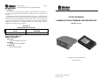
1
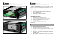
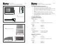
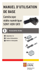
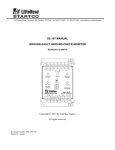
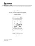
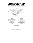
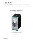
Rev. 1-A-012315 Page 7 AC700-CUA Firmware Upgrade Module 5. WARRANTY The AC700-CUA Communications & Firmware Upgrade Modules are warranted to be free from defects in material and workmanship for a period of five years from the date of purchase. Littelfuse Startco will (at Littelfuse Startco’s option) repair, replace, or refund the original purchase price of an AC700-CUA that is determined by Littelfuse Startco to be defective if it is returned to the factory, freight prepaid, within the warranty period. This warranty does not apply to repairs required as a result of misuse, negligence, an accident, improper installation, tampering, or insufficient care. Littelfuse Startco does not warrant products repaired or modified by non-Littelfuse Startco personnel. 3714 Kinnear Place Saskatoon, SK Canada S7P 0A6 Ph: (306) 373-5505 Fx: (306) 374-2245 www.littelfuse.com/relayscontrols AC700-CUA MANUAL COMMUNICATIONS & FIRMWARE UPGRADE MODULES REVISION 1-A-012315 APPENDIX A AC700-CUA REVISION HISTORY MANUAL RELEASE MANUAL DATE REVISION January 23, 2015 1-A-012315 MANUAL REVISION HISTORY REVISION 1-A-012315 SECTION 2 Updated installation instructions. SECTION 4 Ordering information updated. APPENDIX A Revision history added. Copyright © 2015 by Littelfuse Startco All rights reserved. Document Number: PM-1008-EN Printed in Canada. Rev. 1-A-012315 Rev. 1-A-012315 Page 1 AC700-CUA Firmware Upgrade Module AC700-CUA Firmware Upgrade Module TABLE OF CONTENTS SECTION Page 6 FASTENING REMOVAL PAGE 1 1.1 Introduction ........................................................................................................1 General .......................................................................................................................... 1 1.1.1 Firmware Upgrade Module ............................................................................. 1 1.1.2 Communications Modules .............................................................................. 2 1.2 AC700-CUA Features................................................................................................... 2 1.2.1 Firmware Upgrade Module ............................................................................. 2 1.2.2 Communications Modules .............................................................................. 2 2 Installation.................................................................................................................... 2 2.1 Firmware Upgrade Module Installation ....................................................................... 2 2.2 Communications Module Installation .......................................................................... 4 3 Technical Specifications ............................................................................................. 4 3.1 Firmware Upgrade Module .......................................................................................... 4 3.2 Communications Module.............................................................................................. 4 4 Ordering Information................................................................................................. 6 5 Warranty ...................................................................................................................... 7 Appendix A AC700-CUA Revision History .......................................................................... 7 1 2 3 4 5 NOTE 1 NOTES: 1. THE RECOMMENDED TERMINAL TIGHTENING TORQUE IS 0.25 nM. 2. WHEN FASTENING THE MODULE IN THE END PRODUCT, MAKE SURE THAT THE ANYBUS MODULE IS PROPERLY ALIGNED IN TO THE COMPACTFLASH SOCKET PRIOR TO APPLYING ANY FORCE. ROUGH HANDLING AND/OR EXCESSIVE FORCE IN COMBINATIN WITH MISALIGNMENT MAY CAUSE MECHANICAL DAMAGE TO THE ANYBUS-COMPACTCOM MODULE AND/OR THE END PRODUCT. FIGURE 5. Anybus Communications Module Installation. Shipping Weight ............................ 0.1 kg (0.3 lb) LIST OF FIGURES FIGURE NOTE 1 PAGE Firmware Upgrade Module (AC700-CUA-00) Outline .............................................. 3 Communications Module (AC700-CUA-03) Outline ................................................. 3 Firmware Upgrade Module (AC700-CUA-00) installed in an EL731 ....................... 5 Ethernet/IP Communications Module (AC700-CUA-03) installed in an EL731....... 5 Anybus Communications Module Installation ............................................................ 6 DISCLAIMER Specifications are subject to change without notice. Littelfuse Startco is not liable for contingent or consequential damages, or for expenses sustained as a result of incorrect application, incorrect adjustment, or a malfunction. 1. INTRODUCTION 1.1 GENERAL AC700-CUA is the base model number for the firmware upgrade module and communication modules which can be installed in various products available from Littelfuse. Environment: Operating Temperature ............... -40 to 60°C (-40 to 140°F) Storage Temperature................... -40 to 85°C (-67 to 160°F) Humidity ..................................... 85% Non-Condensing Shock and Vibration: Shock Test .................................... Operating IEC 68-2-27 half-sine 30 g, 11 ms, 3 positive and 3 negative shocks in each of three mutually-perpendicular directions. Shock Test .................................... Operating IEC 68-2-27 half-sine 50 g, 11 ms, 3 positive and 3 negative shocks in each of three mutually-perpendicular directions. Sinusodial Test ............................. Operating IEC 68-2-6 10-500 Hz, 0.35 mm 5 g, 1 oct/min., 10 double sweep in each of three mutually-perpendicular directions. 4. ORDERING INFORMATION AC700-CUA-0 Communications Upgrade Adapter Adapter Type 0 Firmware Upgrade Module 1 DeviceNet™ 2 Profibus® 3 EtherNet/IP™ 4 Modbus® TCP 1.1.1 FIRMWARE UPGRADE MODULE The AC700-CUA-00 is used to upgrade compatible-relay firmware and is fieldinstallable. Detailed instructions are included in the help files of the SE-Flash Firmware Upgrade Software. Field upgrades allow for the addition of new or enhanced features and firmware maintenance. The field upgrade module provides isolation between the unit under service and the computer running SE-Flash. (1) NOTES: (1) Communications adapters can be ordered separately to field upgrade EL731-X0-X0 models. Rev. 1-A-012315 Rev. 1-A-012315 Page 5 Page 2 AC700-CUA Firmware Upgrade Module AC700-CUA Firmware Upgrade Module 1.1.2 COMMUNICATIONS MODULES AC700-CUA serial-communication modules can be factory installed or purchased separately. An existing device not purchased with the communications option can be upgraded in the field. 1.2 AC700-CUA FEATURES 1.2.1 FIRMWARE UPGRADE MODULE RJ45 connector providing TIA232 communication (CA-945 Interface Converter available separately) Mini USB Connector (with included USB cable) 2,500 Vrms isolation Field upgrade capability 1.2.2 COMMUNICATIONS MODULES FIGURE 3. Firmware Upgrade Module (AC700-CUA-00) installed in an EL731. Isolated network interface (on applicable modules) On-board network status indication according to network standard On-board network connectors according to network standard Compact size: 52 x 50 mm (2” x 2”) Pre-compliance tested for CE UL Compliant (documented by UL in file E214107) 2. INSTALLATION NOTE: Before performing service on the device, remove supply and control voltage. 2.1 FIRMWARE UPGRADE MODULE INSTALLATION FIGURE 4. Ethernet/IP Communications Module (AC700-CUA-03) installed in an EL731. Remove system and control voltage from the device. Remove the access panel from device to be upgraded. See Fig. 3. Slide module into opening, such that the rails on the circuit board slot align with the sides of the firmware upgrade module. Apply pressure to ensure proper connection. Install SE-Flash before connecting to the Firmware Upgrade Module. Connect either a TIA-232 or mini USB communications cable between the module and a computer. Follow the SE-Flash help instructions for the product to be upgraded, and apply system power. Rev. 1-A-012315 Rev. 1-A-012315 Page 3 AC700-CUA Firmware Upgrade Module Page 4 AC700-CUA Firmware Upgrade Module 2.2 COMMUNICATIONS MODULE INSTALLATION 42.6 (1.68) 72.2 (2.84) Remove system and control voltage from the device. Remove the access panel from device to be upgraded. See Fig. 3. Slide module into opening, such that the rails on the circuit board slot align with the sides of the communication module. See Figs. 4 and 5. Apply pressure to ensure proper connection while aligning clips to circuit board. Tighten the installation screws using a Torx screwdriver, size 8 (T8). Connect the communications cable as required by the network interface. See the upgraded device’s manual for instructions on how to enable the communications module, and definitions of the LED indications. Apply system power. NOTES: 1. DIMENSIONS IN MILLIMETRES (INCHES). 3. TECHNICAL SPECIFICATIONS 3.1 FIRMWARE UPGRADE MODULE 1.0 (0.04) 8.0 (0.32) Isolation: Device to Network: Voltage ....................................2,500 Vrms Distance...................................7.6 mm (0.3”) FIGURE 1. Firmware Upgrade Module (AC700-CUA-00) Outline. Computer Interface Terminals .......... TIA-232 through RJ45 Connector, Mini USB Dimensions: Height .......................................... 8 mm (0.3”) Width ........................................... 43 mm (1.7”) Depth ........................................... 72 mm (2.8”) Shipping Weight ............................ 0.1 kg (0.3 lb) NOTES: 1. DIMENSIONS IN MILLIMETRES (INCHES). Environment: Operating Temperature ............... -40 to 60C (-40 to 140°F) Storage Temperature................... -55 to 80C (-67 to 160°F) Humidity ..................................... 85% Non-Condensing 22.3 (0.88) 50.1 (1.97) 54.7 (2.15) FIGURE 2. Communications Module (AC700-CUA-03) Outline. 3.2 COMMUNICATIONS MODULE Isolation: Device to Network: Voltage ....................................2,500 Vrms Distance...................................2.5 mm (0.08”) Terminals ........................................... Dependent upon communication standard. Dimensions: Height .......................................... 22 mm (0.9”) Width ........................................... 50 mm (2.0”) Depth ........................................... 52 mm (2.0”)