1
3714 Kinnear Place
Saskatoon, SK
Canada
S7P 0A6
Ph: (306) 373-5505
Fx: (306) 374-2245 www.littelfuse.com/relayscontrols
EL731 MANUAL
AC/DC SENSITIVE
EARTH-LEAKAGE RELAY
REVISION 6-E-091015
Copyright © 2015 by Littelfuse Startco
All rights reserved.
Document Number: PM-1005-EN
Printed in Canada.
EL731 AC/DC Sensitive Earth-Leakage Relay
Factory default password is 1111
New Password
See Section 3.2.4.
Page i
Rev. 6-E-091015
Page ii
Rev. 6-E-091015
EL731 AC/DC Sensitive Earth-Leakage Relay
TABLE OF CONTENTS
SECTION
PAGE
Introduction .............................................................. 1
1.1 General........................................................................ 1
1.2 EL731 Features .......................................................... 1
1.2.1 Protective Functions....................................... 1
1.2.2 Metering.......................................................... 1
1.2.3 Data Logging .................................................. 1
1.2.4 Inputs and Outputs ......................................... 1
1.2.5 Operator Interface .......................................... 1
1.2.6 Communications Interface ............................. 1
2
Installation................................................................. 1
2.1 System Wiring ............................................................ 1
2.1.1 Supply Voltage ............................................... 2
2.1.2 Current Sensor Connections .......................... 2
2.1.3 Analog Output ................................................ 2
2.1.4 PTC or RTD Input.......................................... 2
2.1.5 Communications (Optional) .......................... 2
2.1.6 Remote Reset.................................................. 2
2.1.7 Relay Outputs ................................................. 2
2.2 Calibration .................................................................. 2
3
Operation and Setup ................................................ 7
3.1 Display and Indication ............................................... 7
3.1.1 Front-Panel LED Indication .......................... 7
3.1.1.1 Trip .................................................... 7
3.1.1.2 CT Status ........................................... 7
3.1.1.3 Alarm ................................................. 7
3.1.2 Communications-Module LED
Indication and Status ...................................... 7
3.2 Main Menus................................................................ 7
3.2.1 Metering.......................................................... 7
3.2.2 Messages......................................................... 7
3.2.3 Setup ............................................................... 8
3.2.3.1 Earth-Fault Protection....................... 8
3.2.3.2 Temperature Protection .................... 8
3.2.3.3 Output-Relay Assignments .............. 8
3.2.3.4 Analog Output................................... 8
3.2.3.5 Miscellaneous Configuration ........... 9
3.2.3.5.1 Password ........................... 9
3.2.3.5.2 Reset Password ................. 9
3.2.3.5.3 Menu Timeout .................. 9
3.2.3.5.4 Display Filter .................... 9
3.2.3.5.5 Maintenance ...................... 9
3.2.4 Password ......................................................... 9
3.3 Trip Reset ................................................................... 9
4
Theory of Operation .............................................. 13
4.1 CT1 Theory of Operation ........................................ 13
4.2 CT2 Theory of Operation ........................................ 13
4.2.1 CT2 Full Range Filter .................................. 13
4.2.2 CT2 90 Hz Low Pass Filter ......................... 13
4.2.3 CT2 3 kHz Low Pass Filter ......................... 14
4.2.4 CT2 190 Hz High Pass Filter....................... 14
5
Personal Computer Interface ............................... 14
5.1 Flash Memory Upgrade ........................................... 14
1
SECTION
PAGE
Technical Specifications ........................................ 14
EL731 ....................................................................... 14
EMC Tests................................................................ 15
Certification .............................................................. 16
Current Sensors ........................................................ 16
7
Ordering Information ........................................... 17
8
Warranty ................................................................. 17
9
Performance Test ................................................... 18
10
Maintenance ........................................................... 18
Appendix A EL731 Menu Map........................................ 20
Appendix B System Parameters & Setup Record ......... 22
Appendix C EL731 Revision History .............................. 23
6
6.1
6.2
6.3
6.4
LIST OF FIGURES
FIGURE
PAGE
1
2
3
4
5
EL731 Outline and Mounting Details ........................... 3
AC700-SMK Outline and Mounting Details ................ 4
Panel and Surface Mounting Connections .................... 4
Connection Diagram ...................................................... 5
EL731 with installed EtherNet/IP™
Communications Upgrade Adapter
(AC700-CUA-03).......................................................... 6
6 EL731 with Firmware Upgrade Module
(AC700-CUA-00). ........................................................ 6
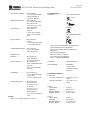
7 EFCT-1 Outline and Mounting Details ....................... 10
8 EFCT-2 Outline and Mounting Details ....................... 11
9 EFCT-26 Outline and Mounting Details ..................... 12
10 PGA-0520 Analog Percent Current Meter .................. 13
11 Earth-Fault-Test Circuit ............................................... 19
LIST OF TABLES
TABLE
1
2
3
4
PAGE
Trip LED Flash Codes ................................................... 7
CT2 Input Filters ............................................................ 8
Output-Relay Functions ................................................. 8
Earth-Fault-Test Record ............................................... 19
DISCLAIMER
Specifications are subject to change without notice.
Littelfuse Startco is not liable for contingent or
consequential damages, or for expenses sustained as a
result of incorrect application, incorrect adjustment, or a
malfunction.
EL731 AC/DC Sensitive Earth-Leakage Relay
This page intentionally left blank.
Page iii
Rev. 6-E-091015
EL731 AC/DC Sensitive Earth-Leakage Relay
1 INTRODUCTION
1.1 GENERAL
The EL731 is a microprocessor-based earth-leakage
relay for AC, DC, combined AC/DC, and variablefrequency power circuits supplied by solidly or
resistance-earthed systems that require earth-leakage
detection as low as 30 mA (under default configuration).
Earth-leakage metering and two setting levels (alarm and
trip) are provided. It is uniquely suited for sensitive
earth-fault protection for adjustable-speed drive (ASD)
circuits that often operate at low speeds. A temperaturesensor input provides metering and protection for a
motor or ASD.
Settings and configuration selections provide
frequency-response ranges of 0 to 90 Hz, 20 to 90 Hz,
190 to 6,000 Hz, 20 to 6,000 Hz, 20 to 3,000 Hz and 0 to
6,000 Hz.
Three Form-C (changeover) output relays with
normally closed and normally open contacts can be
programmed for various functions and can be set to
operate
in
the
fail-safe
or
non-fail-safe modes for undervoltage or shunt-trip
applications.
Additional features include a 2 x 16-character OLED
alphanumeric display, current and temperature metering,
programming and menu-navigation push buttons,
password security, LED trip and alarm indication, autoreset alarms and latching trips with front-panel and
remote reset, trip memory, 4- to 20-mA analog output,
CT verification with LED indication, and conformalcoated circuits.
Earth-leakage current is sensed by one or two EFCTseries core-balance zero-sequence current transformers.
The alarm- and trip-level ranges of the earth-leakage
circuit are 30 to 5,000 mA. To modify this range,
firmware settings for each CT input allow configuring
the number of phase-conductor turns that are passed
through the CT-primary window – the lowest pickup
configuration is 6 to 1,000 mA, with a setting of five
turns. With two CT’s connected, the EL731 performs
independent metering. The trip-time delay has a definitetime characteristic and is configurable from
instantaneous to two seconds in millisecond increments.
1.2 EL731 FEATURES
1.2.1 PROTECTIVE FUNCTIONS
AC ground overcurrent (50G/51G, 50N/51N)
DC ground overcurrent (76G)
PTC overtemperature (49)
RTD temperature (38, 49)
1.2.2 METERING
Earth-leakage current, CT1 and CT2
RTD temperature or PTC status
Page 1
Rev. 6-E-091015
1.2.3 DATA LOGGING
Trip counters
Alarm counters
1.2.4 INPUTS AND OUTPUTS
AC earth-leakage current transformer (CT2)
AC/DC earth-leakage current transformer (CT1)
Remote reset input (one shot operation)
Network communications (optional)
4-20-mA analog output, programmable, loop powered
Temperature-sensor input, Pt100 RTD or PTC
Three output relays, programmable
1.2.5 OPERATOR INTERFACE
2 x 16 OLED alphanumeric display
Display-control and programming buttons
LED status indication
1.2.6 COMMUNICATIONS INTERFACE
The EL731 interface for optional network
communications adapters supports DeviceNet™,
Profibus®, EtherNet/IP®, and Modbus® TCP. Units
purchased without a communications adapter can be
field-upgraded.
An optional firmware upgrade module is available for
firmware upgrades.
For ordering information, see Section 7.
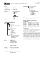
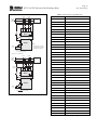
2. INSTALLATION
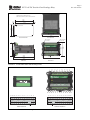
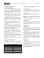
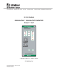
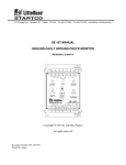
Outline and details for panel-mounting an EL731 are
shown in Fig. 1. Insert the EL731 through the cutout and
slip the panel-mount clamp over the EL731 body. Slide
the panel-mount clamp forward to engage the latch tabs
with the mating body retainer grooves. Lock the unit in
place by tightening the four clamp screws against the
panel.
NOTE: Do not over tighten the clamp screws as this
might deform the clamp and release the latch tabs. The
maximum recommended torque is 0.28 N-m (2.5 in-lb).
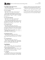
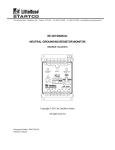
Outline and details for surface-mounting the EL731
are shown in Fig. 2. A detailed instruction sheet is
included with the optional AC700-SMK SurfaceMounting Hardware Kit.
2.1 SYSTEM WIRING
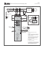
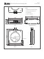
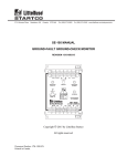
A typical connection diagram for the EL731 is shown
in Fig. 4 and terminal-layout diagrams are shown in
Fig. 3.
A minimum 75°C (167°F) wire-temperature rating is
required.
EL731 AC/DC Sensitive Earth-Leakage Relay
2.1.1 SUPPLY VOLTAGE
Provide supply voltage from the line side of the
controller or from an independent source. Connect
supply voltage to terminals 14 and 15 (L1, L2/N) as
shown in Figs. 3 and 4. In 120-Vac systems, L2/N is
designated as the neutral conductor. For direct-current
power supplies, use L1 for the positive terminal and
L2/N as the negative terminal. Connect terminal 16 ( )
to earth.
2.1.2 CURRENT SENSOR CONNECTIONS
This earth-leakage relaying system consists of an
EL731 earth-leakage relay and one or two EFCT-series
current sensors connected as shown in Fig. 4. The
system can use CT1 and CT2 individually or combined.
See Section 4.
Pass the phase conductors through the CT window(s)
and position them in the centre of the opening (for 4-wire
and single-phase systems, also pass the neutral conductor
through the CT window). Do not pass earth conductors
through the CT window. In applications that require
shields or drain wires to pass through the CT window,
return them through the CT window before connecting
them to earth. For applications utilizing the primaryturns feature, pass the phase conductors through the
opening additional times as required (maximum of 5).
Using shielded twisted-pair cable, connect CT1 to
terminals 7 and 8 and connect the shield to terminal 6.
Current-sensor connections are not polarity sensitive.
See Figs. 7, 8 and 9 for current-sensor dimensional
drawings.
Using shielded twisted-pair cable, connect CT2 to
terminals 10 and 11 and connect the shield to terminal 9.
Current-sensor connections are not polarity sensitive.
See Figs. 7, 8 and 9 for current-sensor dimensional
drawings.
Each EFCT-series sensor includes 6 m (19.2’) of
cable.
NOTE: CT1 emits an audible tone when operating
properly.
2.1.3 ANALOG OUTPUT
The 4-20-mA analog output is loop powered. Connect
as shown in Fig. 4. The analog output is isolated to 120
Vac from all other EL731 terminals.
2.1.4 PTC OR RTD INPUT
The temperature-sensor input can be configured for
either RTD or PTC operation. Connect as shown in
Fig. 4.
Select the sensor type in the Setup | Hardware | Temp
Sensor menu.
Page 2
Rev. 6-E-091015
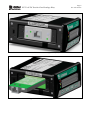
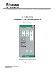
2.1.5 COMMUNICATIONS (OPTIONAL)
The EL731 supports optional communications upgrade
adapters which install through the side of the enclosure
as shown in Fig. 5.
To
field-install
an
AC700-CUA-series
Communications Upgrade Adapter, follow this
procedure:
Remove supply voltage from the EL731.
Remove the adapter access cover on the side of the
EL731.
Insert the adapter, and retain with the supplied
screws.
Apply supply voltage to the EL731.
With an EtherNet/IP or Modbus TCP communications
adapter installed, a standard RJ45 network cable can be
used to connect the EL731 to an EtherNet/IP or Modbus
TCP network. Configure the interface using the IP
Configuration Tool (IP Config) available at
www.littelfuse.com/relayscontrols.
The
software
requires a Microsoft Windows™ operating system. The
Ethernet interface supports 10/100-Mbit, full- or halfduplex operation.
Connect the EL731 to the network using a standard
Ethernet patch cable. Use of a crossover cable to connect
the EL731 directly to the computer running IP Config is
not recommended. A typical router will assign an IP
address to all connected computers that are using DHCP.
The EL731 is not configured to accept an IP address
using DHCP.
If the EL731 is being set up for first time, it is
recommended to only have one EL731 connected to the
network to prevent communication errors.
With a DeviceNet communications adapter installed, a
standard open-style device cable can be used to connect
the EL731 to a DeviceNet network. Configure the
address and baud rate through the EL731 front-panel
interface or with Rockwell Automation’s RSNetWorx
software. The DeviceNet interface supports baud rates
of 125, 250, and 500 kbps.
2.1.6 REMOTE RESET
If required, connect a normally open momentary
switch to the remote-reset input (terminals 12 & 13) as
shown in Fig. 4.
2.1.7 RELAY OUTPUTS
The EL731 has three programmable Form-C
(changeover) relay outputs. Functional assignments are
Trip, Alarm, Watchdog or Current Detected. See Section
3.2.3.3.
2.2 CALIBRATION
If the low-frequency CT1 input is used, the EL731
must be calibrated in order to ensure an accurate current
measurement.
Page 3
Rev. 6-E-091015
EL731 AC/DC Sensitive Earth-Leakage Relay
To calibrate, connect an EFCT-series current sensor to
the EL731 and ensure that no CT-primary current is
present. Apply EL731 supply voltage and navigate to
menu item Setup | Protection | CT1 Earth Fault |
Calibrate. Press Enter to begin the calibration process.
The CT LED will flash, during the calibration process,
which takes about 30 seconds.
If the CT is replaced, this procedure must be repeated
to maintain current-measurement accuracy.
NOTES:
1. DIMENSIONS IN MILLIMETRES (INCHES).
REAR
91.5
(3.60)
92.0
(3.62)
EL731-01
EL73101-10
AC/DC SENSITIVE
EARTH-LEAKAGE RELAY
R
C
Vac (+10, -45%) 50/60 Hz
~ 13 VA 120-240
7 W 100-250 Vdc (+10, -25%)
Supply:
US
LR 53428
(1.73)
Contact Ratings for Relay 1:
8 A 250 Vac 500 VA/8 A 30 Vdc 48 W
Relay 2 & 3:
5 A 250 Vac 300 VA/5 A 30 Vdc 28 W
Network Communications:
50.0 MINIMUM
(1.97)
44.0
R=4.8 (0.19)
MAXIMUM
100.0 MINIMUM
®
N11659
Ground Fault Sensing
and Relaying Equipment
4FX9 E340889
AS/NZS 2081:2011 Compliant
DeviceNet™
Revision:
Serial No:
1-800-TEC-FUSE (1-800-832-3873)
Made in Saskatoon, Canada
AS/NZS 2081: 2011
Section 6 Compliant
Associated Equipment:
EFCT-1, EFCT-2, EFCT-26, EFCT-5RF EFCT-6RF, EFCT-7RF,
EFCT-8RF,EFCT-9RF, EFCT-10RF Current Transformers
Operating Time:
35 ms minimum
500 ms maximum
50 A maximum
2.5 s withstand
Operating Current:
(3.94)
PANEL CUTOUT DETAIL
PANEL THICKNESS
1.6 (0.06) TO 4.8 (0.19)
TOP
PANEL-MOUNT CLAMP
COMMUNICATIONS
ADAPTER
ACCESS COVER
10.0
(0.39)
96.0
(3.78)
43.9
(1.73)
48.0
(1.89)
119.0 MAX
(4.68)
SIDE
CLAMP RETAINER
GROOVES
FIGURE 1. EL731 Outline and Mounting Details.
FRONT
Page 4
Rev. 6-E-091015
EL731 AC/DC Sensitive Earth-Leakage Relay
NOTES:
1. DIMENSIONS IN MILLIMETRES (INCHES).
2. SIDE VIEW SHOWN WITH 35 MM x 7.5 MM TOP-HAT RAIL.
21.2
(0.83)
112.0
(4.41)
100.0
(3.94)
12.0
(0.47)
60.0
(2.36)
81.2
(3.20)
M4 OR 8-32 TAP
112.0
(4.41)
BOTTOM VIEW
CABLE-TIE EYELET
4 LOCATIONS
60.0
(2.36)
81.2
(3.20)
81.2
M4 OR 8-32 TAP
4 LOCATIONS
(3.20)
MOUNTING DETAIL
121.9
(4.80)
125.4
(4.94)
100.0
(3.94)
SIDE VIEW
FRONT VIEW
FIGURE 2. AC700-SMK Outline and Mounting Details.
14
RST GND S21 S22
13
12
11
REMOTE
RESET
26
RELAY 3
25
24
K3
10
CT2
23
SH2 S11
9
8
S12 SH1
7
6
TC
5
CT1
RELAY 2
22
21
K2
20
TB
TA
4
3
RTD / PTC
RELAY 1
19
18
K1
17
NC
16
AB
AA
2
1
1
2
15
16
AB
TA
1
2
3
ANALOG OUT
POWER
14
15
POWER
15
14
L1
PANEL MOUNTED
FIGURE 3. Panel and Surface Mounting Connections.
L1
L2/N
5
4
18
17
AA
ANALOG OUT
L2/N
3
7
8
19
20
21
S12 S11
TB
TC
SH1
4
5
6
RTD / PTC
7
8
17
NC
22
18
19
K1
23
SH2 S22
9
CT1
10
12
24
11
21
22
25
26
12
13
REMOTE
RESET
RELAY 2
20
13
S21 GND RST
CT2
RELAY 1
16
11
10
9
6
RELAY 3
23
K2
SURFACE MOUNTED
24
25
K3
26
Page 5
Rev. 6-E-091015
EL731 AC/DC Sensitive Earth-Leakage Relay
NOTE 5
EFCT-X
EFCT-X
ØA
ADJUSTABLESPEED
DRIVE
(ASD)
ØB
ØC
NEUTRAL-EARTHING
RESISTOR
L1
L2/N
6
NOTE 5
14
7
8
9
10
11
SH1 S12 S11
SH2 S22 S21
CT1
CT2
L1
NOTE 3
L2/N
GROUNDED
DC SYSTEM
15
20
N
ASD
RUN
7
18
K2
21
22
8
20
EL731
FAULT
DC CIRCUIT
MONITORING
23
K3
25
-
NOTE 6
K1
19
EFCT-X
+
24
26
REMOTE
RESET
13
12
17
TC
5
TC
RTD/PTC TB
4
TB
TA
3
TA
RST
GND
NC
ANALOG
OUT
16
AB
AA
PTC
RTD
tº
+tº
TB
TA
SUPPLY
+
-
2
1
TC
4-20 mA
PGA-0520
NOTES:
DISPLAY:
2 x 16
ALPHANUMERIC
OLED
INDICATION
R
TRIP
Y
ALARM
G
CT
EL731
OPTIONAL NETWORK
COMMUNICATIONS
1. CT CONNECTIONS ARE NOT POLARITY
SENSITIVE.
2. CT1 AND CT2 ARE INTERNALLY REFERENCED TO
TERMINAL 16. DO NOT CONNECT ADDITIONAL
EARTHS TO CT1 OR CT2.
3. FREQUENCY RESPONSE OF CT1 IS DC TO 90 HZ
AND CT2 IS 20 TO 6,000 HZ. USE ONE OR BOTH
INPUTS TO PROVIDE DESIRED FREQUENCY
RESPONSE. SEE SECTION 4.
4. RELAY CONTACTS SHOWN WITH THE EL731
DE-ENERGIZED.
5. ALTERNATE CT LOCATIONS.
6. IF A GROUND-FAULT OCCURS IN THE RECTIFIER
PORTION OF AN ASD, THIS CONTROL SCENARIO
MIGHT BE INSUFFICIENT. TRIP THE CIRCUIT
BREAKER UPSTREAM FROM THE ASD.
FIGURE 4. Connection Diagram.
EL731 AC/DC Sensitive Earth-Leakage Relay
FIGURE 5. EL731 with installed EtherNet/IP™ Communications Upgrade Adapter (AC700-CUA-03).
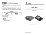
FIGURE 6. EL731 with Firmware Upgrade Module (AC700-CUA-00).
Page 6
Rev. 6-E-091015
EL731 AC/DC Sensitive Earth-Leakage Relay
3. OPERATION AND SETUP
3.1 DISPLAY AND INDICATION
The EL731 front panel has three LED’s, a
2-line x 16-character alphanumeric OLED display and
four push buttons to navigate through programming,
status, and system-information menus. The display will
revert to screen-saver mode after 10 minutes. Press any
button to exit the screen saver.
The RESET button is used to clear an earth-leakage or
overtemperature trip. The fault condition must no longer
be present to allow a reset. Continually pressing the
reset button will not prevent a trip.
The RESET button has a second function that is useful
when navigating the menus. If the button is pressed for a
short time, upon release the active menu item will exit,
either returning to the previous menu item or the status
screen.
The up and down arrow buttons (▲▼) are used to
navigate the menu system or modify settings.
The ENTER button is used to select menu items and to
choose settings.
All EL731 settings can be accessed using the EL731
menu system or the optional network communications
interface. In the following sections, menu items and
setup parameters are listed in italics and are shown in the
format displayed on the OLED display.
Menu selection is in the following format:
Menu 1 | Sub Menu 1 | Sub Menu 2 | Sub Menu 3 |…
When browsing a selection list, an asterisk (*)
indicates the active item. If the intent is to exit the list
and not to change the setting, press ENTER on the
selection that has the asterisk (*).
If the item is a string (or numerical) input and no
change is desired, press ENTER until the display returns
to the menu system. To exit a main-menu list, scroll and
select Exit, or press the RESET button.
A menu map is provided in Appendix A at the end of
this manual.
3.1.1 FRONT-PANEL LED INDICATION
3.1.1.1 TRIP
The red LED labelled TRIP indicates a trip condition
when flashing. Refer to Table 1 for applicable flash
codes.
TABLE 1. TRIP LED FLASH CODES
FAULT
CODES
CT1 Earth Fault
CT2 Earth Fault
CT1 Detection Failure
CT2 Detection Failure
NVRAM Error
CT1 Calibration Failure
RTD/PTC Trip
User Test
Watchdog
1 Short, 1 Long
2 Short, 1 Long
3 Short, 1 Long
4 Short, 1 Long
5 Short, 1 Long
6 Short, 1 Long
7 Short, 1 Long
8 Short, 1 Long
Fast Flash
Page 7
Rev. 6-E-091015
Trip cause is also available on the OLED display
through the Messages | State menu item.
3.1.1.2 CT STATUS
The green LED labelled CT will flash during CT1
calibration. It will be solid green when CT connections
are correct, and off when a CT is connected incorrectly.
3.1.1.3 ALARM
The yellow LED labelled ALARM will be on when
measured current is above the alarm setting.
3.1.2 COMMUNICATIONS-MODULE LED INDICATION AND
STATUS
See the associated interface manual, available at
www.littelfuse.com/relayscontrols.
3.2 MAIN MENUS
The “top” menu item (select Exit in the main menu)
displays earth-leakage current(s) as a numeric percentage
of full scale (5 A, depending upon the primary turns
setting) and as a bar graph.
3.2.1 METERING
Menu: Metering
With Metering selected in the main menu, press the
ENTER button to display a list of metering options. Use
the Up and Down arrow buttons to scroll through the
options list. Press the ENTER button to display the
selected information.
Information available: CT1 primary current (mA),
CT2 primary current (mA), combined CT1 and CT2
current (mA), internal EL731 temperature (°C and °F),
PTC status, and RTD temperature (°C and °F).
The CT2 metering range is trip-level dependent.
When the CT2 trip level is set to less than 250 mA, the
CT2 meter range is 0 to 2.5 A. When the CT2 trip level
is set to greater than or equal to 250 mA, the meter range
is 0 to 5 A.
3.2.2 MESSAGES
Menu: Messages
Selecting this menu item allows the trip state, alarm
state, trip counter, alarm counter, system uptime, and
running time to be viewed.
System uptime is the amount of time since the last
restart or supply voltage cycle. Running time is the total
amount of time the system has been in operation, and is
retained through power cycles.
Page 8
Rev. 6-E-091015
EL731 AC/DC Sensitive Earth-Leakage Relay
3.2.3 SETUP
See Appendix B for a Setup Summary and Setting
Record.
3.2.3.1 EARTH-FAULT PROTECTION
Menu: Setup | Protection | CTx Earth Fault
The Earth Fault Enable/Disable menu enables or
disables current monitoring through the selected CT input.
When enabled, the system checks to ensure the CT is
connected properly. A trip will occur if an EFCT is not
connected. See Section 3.1.1.1.
The Primary Turns menu sets the number of passes
through the CT primary by the phase conductors. The
range is 1 to 5 turns, where 1 is the default. If set to
another value, ensure the phase conductors pass through
the CT window the correct number of times. This setting
affects the trip/alarm range.
The Trip Time menu sets the trip delay. The range is 0 to
2 seconds in millisecond increments where 0 indicates that
as soon as current is detected above the Trip Level, a trip
occurs.
The Trip Level menu sets the trip level. The default
setting range is 30 mA to 5 A, but this is affected by the
Primary Turns setting. The Alarm Level setting range is
the same as the Trip Level range. Trips are latched,
requiring a local or remote reset input, and alarms autoreset.
The Calibrate menu applies to CT1 (0 to 90 Hz). When
CT1 is used, the EL731 must be calibrated after
installation. See Section 2.2.
The Input Filter menu applies to CT2 (20 to 6,000 Hz)
and allows selection of different input filters. The available
filters and their descriptions are shown in Table 2.
FILTER
TABLE 2. CT2 INPUT FILTERS
FREQUENCY RESPONSE
Full Range (Default)
90 Hz Low Pass Filter
190 Hz High Pass Filter
3 kHz Low Pass Filter
20 to 6,000 Hz
20 to 90 Hz
190 to 6,000 Hz
20 to 3,000 Hz
For full-spectrum protection, use CT1 and CT2 and
select the 190 Hz High Pass Filter to avoid frequency
overlap between the inputs.
3.2.3.2 TEMPERATURE PROTECTION
Menu: Setup | Protection | PTC Local Temp
Menu: Setup | Protection | RTD Local Temp
Menu: Setup | Hardware | Temp Sensor
The temperature-sensor input, at terminals 3, 4, and 5,
can be configured as a PTC thermistor or a 100-ohmplatinum RTD (or disabled) in the Setup | Hardware |
Temp Sensor menu. Overtemperature alarm and trip
actions can be selected in the Setup | Protection | PTC
Temperature menu, or in the Setup | Protection | RTD
Temperature menu.
3.2.3.3 OUTPUT-RELAY ASSIGNMENTS
Menu: Setup | Relay Outputs | Relay x
Each of the three output relays can be assigned to one
of the functions listed in Table 3. More than one output
can be assigned the same function.
TABLE 3. OUTPUT-RELAY FUNCTIONS
FUNCTION ASSIGNMENT OR
DEFAULT
ASSIGNMENT
ACTION
Trip
Alarm
Watchdog
Current
Detected
(1)
Relay de-energized in failsafe mode when trip occurs.
Fail-safe or non-fail-safe(1)
mode selection is available.
Relay de-energized in failsafe mode when alarm is
present. Fail-safe or nonfail-safe(1) mode selection is
available.
Relay is energized in failsafe mode when the supply
voltage is applied and the
EL731 is operating
properly. Fail-safe or nonfail-safe mode selection is
available.
Relay is energized in failsafe mode when current is
detected on CT1 or CT2.
Fail-safe or non-fail-safe
mode selection is available.
Relay 1, Fail-safe
Mode
Relay 2, Fail-safe
Mode
Relay 3, Fail-safe
Mode
Fail-safe Mode
Fail-safe only for AS/NZS 2081:2011 option.
The Fail-safe Mode setting for each output relay
allows the individual output relay to be configured as
fail-safe (normally energized) or non-fail-safe (normally
de-energized).
The Test function performs a test of the specified
relay. During the test, the relay is energized for one
second and de-energized for one second. This sequence
is performed once per test.
3.2.3.4 ANALOG OUTPUT
Menu: Setup | Analog Output
A 4- to 20-mA programmable current output is
provided.
When Analog % Level is enabled the output is
configured such that 20 mA corresponds to full scale of
the selected CT Trip Level.
When disabled it
corresponds to the full scale of the selected CT.
CT Select selects which CT measurement will be
represented by the analog output. The selections are CT1,
CT2, and Full Current. When set to Full Current, the
current measured by each CT makes up 50% of the total
Analog Output level.
Output Filter passes the output through an averaging
filter, providing a smoother analog output signal in
noisier applications.
EL731 AC/DC Sensitive Earth-Leakage Relay
3.2.3.5 MISCELLANEOUS CONFIGURATION
Menu: Setup | System Config
Used to access additional system configuration elements
described in the following sections.
3.2.3.5.1 PASSWORD
Menu: Setup | System Config | Change Password
Menu: Setup | System Config | Password Enable
Used to enable and change the EL731 password (fourcharacter numeric field). When enabled, the password
must be entered to change a set point. The default
password is 1111.
3.2.3.5.2 RESET PASSWORD
Menu: Setup | System Config | Chg Reset Pwd
Menu: Setup | System Config | Reset Pwd En
Used to enable and change the EL731 reset password
(four-character numeric field). When enabled, the reset
password must be entered to reset the EL731. The
default reset password is 1111.
3.2.3.5.3 MENU TIMEOUT
Menu: Setup | System Config | Menu Timeout
Used to set the time before the system times out due to
lack of activity and the menu system returns to the main
menu display (See Section 3.2). In password mode the
password entered will be cleared. The timeout is
measured from the last button press.
The display will revert to screen-saver mode 10
minutes after the menu timeout occurs.
3.2.3.5.4 DISPLAY FILTER
Menu: Setup | System Config | Display Filter
Used to enable an averaging filter for current displayed
on the display through the metering menu. See Section
3.2.1.
3.2.3.5.5 MAINTENANCE
Menu: Setup | System Config | Maintenance
Used to clear trip and alarm counters, load defaults,
restart the system, and display the model option,
firmware version, build date, and serial number.
3.2.4 PASSWORD
Menu: Password
With password security active, all set points are
locked. To enable programming, the password must be
entered through the Password menu.
While navigating through the menus when a valid
password has been entered, an asterisk (*) is shown at
the beginning of the first line of the display.
3.3 TRIP RESET
The RESET button will clear a trip when pressed for
2.5 s if the fault is no longer present. Keeping RESET
pressed will not prevent an alarm or trip. If the reset
Page 9
Rev. 6-E-091015
password is enabled, reset will not function until the
password has been entered through the Password menu.
Momentarily connect Remote Reset terminals 12 and
13 for 2.5 s to reset a trip when the fault is no longer
present.
If an optional network adapter is installed, an EL731
trip can be reset with a network command when the fault
is no longer present, even if a reset password is enabled.
Page 10
Rev. 6-E-091015
EL731 AC/DC Sensitive Earth-Leakage Relay
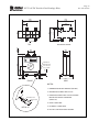
NOTES:
1. DIMENSIONS IN MILLIMETRES (INCHES).
2. MOUNTING SCREWS: M4 OR 8-32.
3. PRESS MOUNTING FEET IN PLACE USING
INSTALLATION TOOL PROVIDED.
4. RoHS COMPLIANT.
5. EN 60044-1 COMPLIANT.
121.0
(4.76)
121.0
(4.76)
20.5
(0.81)
56.0
(2.21)
46.0
(1.81)
30.0
(1.18)
80.0
(3.15)
NOTE 2
M5 SCREWS
TOP
MOUNTING DETAIL
25.0
(0.98)
30.0
(1.18)
EFCT-1 EARTH FA ULT CT
600 V CLASS, INSULATION CLASS A
R
R
LR 53428
5.0 (0.20) Ø
RECESSED FOR
8-mm HEX NUT
1.0 (0.04) DEEP
22.0
(0.87)
EFCT - 1FC
FLUX
CONDITIONER
(OPTIONAL)
.0
82 23)
.
(3
69
(2.7 .8
5)
126.0
(4.96)
US
(5.43)
138.0 MAX
C
5.5
(0.22)
110.0
(4.33)
FRONT
FIGURE 7. EFCT-1 Outline and Mounting Details.
5.5
(0.22)
56.0
(2.21)
SIDE
Page 11
Rev. 6-E-091015
EL731 AC/DC Sensitive Earth-Leakage Relay
NOTES:
1. DIMENSIONS IN MILLIMETRES (INCHES).
2. MOUNTING SCREWS: M5 OR 10-32.
3. RoHS COMPLIANT.
4. EN 60044-1 COMPLIANT.
215.0
(8.46)
26.5
(1.04)
52.3
(2.06)
P
S1 2S2
P1
31.0
(1.22)
64.0
(2.52)
215.0
(8.46)
162.0
(6.38)
M5 OR 10-32 TAP
M5 SCREWS
TOP
MOUNTING DETAIL
31.0
(1.22)
25.0
(0.98)
EFCT-2 EARTH FAULT CT
600 V CLASS, INSULATION CLASS A
R
R
LR 53428
139.7
(5.50)
FLUX CONDITIONER
(INCLUDED)
BONDING
SCREW
215.0
(8.46)
US
5.0 (0.20) DIA
60.0
(2.36)
236 MAX
(9.29)
C
8.5
(0.33)
198.0
(7.80)
FRONT
FIGURE 8. EFCT-2 Outline and Mounting Details.
8.5
(0.33)
SIDE
Page 12
Rev. 6-E-091015
EL731 AC/DC Sensitive Earth-Leakage Relay
68.0
(2.68)
68.0
(2.68)
17.0
(0.67)
P
S1 2 S2
P1
M4 OR 8-32 TAP
42.6
(1.68)
52.5
(2.07)
26.5
(1.04)
34.0
(1.34)
M5 SCREWS
110.0 MAX
(0.43)
TOP
MOUNTING DETAIL
26.5
(1.04)
25.0
(0.98)
E F C T- 2 6
E A R T H FA U LT C T
600 V CLASS, INSULATION CLASS A
R
R
C
LR 53428
US
RECESSED FOR
7-mm HEX NUT
3.0 (0.12) DEEP
7.0
(0.87)
34.0
(1.34)
72.0
(2.83)
4.0 (0.16) Ø
.0
26 2)
0
(1.
58.0
(2.28)
52.5
(2.07)
5.0
(0.20)
5.0
(0.20)
FRONT
SIDE
NOTES:
1. DIMENSIONS IN MILLIMETRES (INCHES).
2. MOUNTING SCREWS: M4 OR 8-32.
MOUNTING FOOT
INSTALLATION
TOOL
3. PRESS MOUNTING FEET IN PLACE USING
INSTALLATION TOOL PROVIDED.
(DETAIL ‘A’)
4. RoHS COMPLIANT.
DETAIL ‘A’
5. EN 60044-1 COMPLIANT.
6. NOT ALL CERTIFICATIONS SHOWN.
FIGURE 9. EFCT-26 Outline and Mounting Details.
Page 13
Rev. 6-E-091015
EL731 AC/DC Sensitive Earth-Leakage Relay
67.5
(2.657)
67.5
(2.657)
48.0
(1.890)
66.0
(2.598)
R1.25(0.049)
MAXIMUM
TOP
MOUNTING CUTOUT
100
60
40
®
20
65.0
(2.559)
80
1. DIMENSIONS IN MILLIMETRES (INCHES).
71.0
(2.795)
%
NOTES:
0
PGA-0520
ANALOG % CURRENT METER
FRONT
SIDE
REAR
FIGURE 10. PGA-0520 Analog Percent Current Meter.
4. THEORY OF OPERATION
CT1 and CT2 have independent Trip and Alarm
current-level and time-delay set points and independent
metering. This enables different protection levels and
separate metering for the high- and low-frequency
ranges.
Full-current metering, summing CT1 and CT2
metering, is provided as an OLED metering selection, an
analog output selection, and in optional network
communications.
To improve full-current-metering
accuracy by avoiding band overlap, select the CT2 highpass filter.
For CT-location and variable-speed-drive-application
information, see Technical Note GF-11 “Ground-Fault
Monitoring in Adjustable-Speed Drive Applications”
located at www.littelfuse.com/relayscontrols.
4.1 CT1 THEORY OF OPERATION
The EL731 applies a known signal to the secondary
winding of the EFCT-series sensor connected to input
CT1. Current flowing in the EFCT primary affects this
signal, and its magnitude can be accurately measured
across a wide frequency range. The EL731 can measure
current as low as 30 mA (6 mA with primary turns
setting) in a frequency range of 0 to 90 Hz. If an open or
short EFCT connection is detected, a trip occurs.
Compatible CT’s include the EFCT-1, EFCT-2, and
EFCT-26. See Section 7.
4.2 CT2 THEORY OF OPERATION
CT2 is a core-balance zero-sequence currenttransformer application, with digital filtering to enable a
wide spectrum of detection.
There are four digital-filter ranges: Full Range, 90 Hz
Low Pass, 3 kHz Low Pass, and 190 Hz High Pass.
If an open or short EFCT connection is detected, a trip
occurs. See Table 1.
Compatible CT’s include the EFCT-1, EFCT-2,
EFCT-26, and the EFCT-xRF series. See Section 7.
4.2.1 CT2 FULL RANGE FILTER
The Full Range filter selection configures the EL731
to respond to the entire frequency spectrum that CT2 is
capable of monitoring – 20 to 6,000 Hz.
4.2.2 CT2 90 Hz LOW PASS FILTER
The 90 Hz Low Pass filter selection configures the
EL731 to respond to only the low end of its frequency
range, 20 to 90 Hz.
EL731 AC/DC Sensitive Earth-Leakage Relay
4.2.3 CT2 3 kHz LOW PASS FILTER
The 3 kHz Low Pass filter selection configures the
EL731 to respond to the 20 to 3,000 Hz frequency range.
4.2.4 CT2 190 Hz HIGH PASS FILTER
The 190 Hz High Pass filter selection configures the
EL731 to respond to only the high end of its frequency
range, 190 to 6,000 Hz.
5. PERSONAL COMPUTER INTERFACE
5.1 FLASH MEMORY UPGRADE
The EL731 control program is stored in flash memory.
This allows field upgrades to be made through the
upgrade module (optional). The following are required:
Windows PC with a USB interface and the SE-Flash
program installed; SE-Flash is available at
www.littelfuse.com/relayscontrols
File containing the EL731 control program (.s19 file)
USB cable or a TIA232 (through a CA-945
converter) with Ethernet cable
AC700-CUA-00 Firmware Upgrade Module
6. TECHNICAL SPECIFICATIONS
6.1 EL731
Supply:
Option 0 .................................13 VA, 120 to 240 Vac
(+10, - 45%), 50/60 Hz;
7 W, 100 to 250 Vdc
(+10, - 25%)
Option 1 .................................7 W, 32 to 60 Vdc
(+20,-25%),
Nominal 48 Vdc;
9 VA, 24 to 44 Vac
(±10%), 50/60 Hz
Option 2 .................................7 W, 16 to 30 Vdc
(+20,-25%),
Nominal 24 Vdc
DC and Low Frequency (Current Transformer 1):
Frequency Response ........... DC to 90 Hz
Measurement Method ......... True RMS
Detection Method ............... CT Driven Oscillator
Trip-Level Setting............... 30 to 5,000 mA
Trip-Level Primary Turns
Lowest Alternate Range... 6 to 1,000 mA
Alarm-Level Setting ........... 30 to 5,000 mA
Alarm-Level Primary Turns
Lowest Alternate Range... 6 to 1,000 mA
Trip-Time Settings .............. 0 to 2 s
AS/NZS 2081 Option....... 0 to 500 ms
Trip Accuracies:
Trip Level ........................ Maximum of 10%
Time Delay(1) ................... - 5% setting + 35 ms
CT ....................................... EFCT series
Cable Resistance ................. 1 Ω Maximum
Page 14
Rev. 6-E-091015
Thermal Withstand:
Continuous ....................... 25 A Earth-Fault
Current
1 second ........................... 400 A Earth-Fault
Current
Detection ............................. CT Open & Short
AC/Carrier (Current Transformer 2):
Frequency Response:
Full Range Filter .............. 20 to 6,000 Hz
90 Hz Low Pass Filter ..... 20 to 90 Hz
190 Hz High Pass Filter ... 190 to 6,000 Hz
3 kHz Low Pass Filter ...... 20 to 3,000 Hz
Measurement Method ......... True RMS
Detection ............................. CT Open & Short
Meter Range:
Trip Level < 250 mA........ 0 to 2.5 A
Trip Level ≥ 250 mA........ 0 to 5 A
Trip Level Setting ............... 30 to 5,000 mA
Trip-Level Primary Turns
Lowest Alternate Range ...... 6 to 1,000 mA
Alarm Level Setting ............ 30 to 5,000 mA
Alarm-Level Primary Turns
Lowest Alternate Range ...... 6 to 1,000 mA
Trip-Time Settings .............. 0 to 2 s
AS/NZS 2081 Option ....... 0 to 500 ms
Trip Accuracies:
Trip Level:
30 to 5,000 mA .............. Maximum of 10% (at
50/60 Hz)
Trip Time(1) ...................... - 5% setting + 25 ms
(at 50/60 Hz)
CT ....................................... EFCT and
EFCT-RF(2) series
Cable Resistance ................. 1 Ω Maximum
Thermal Withstand:
Continuous ....................... 25 A Earth-Fault
Current
1 second ........................... 400 A Earth-Fault
Current
Detection ............................. CT Open, Short, and
Saturation
Output Relays:
Relay 1:
Contact configuration ....... N.O. and N.C., Form-C,
changeover
Operating Mode ............... Fail-Safe/Non-Fail-Safe
CSA/UL Rating ................ 8 A Resistive, 250 Vac,
8 A Resistive, 30 Vdc
AS/NZS 2081 Rating ....... 8 A Resistive, 250 Vac,
500 VA
8 A Resistive, 30 Vdc,
48 W
Supplemental Contact Ratings
Make/Carry 0.2 s ........... 30 A
Rating Code ................... B300
EL731 AC/DC Sensitive Earth-Leakage Relay
Break:
dc................................. 50 W Resistive, 150 Vdc
ac ................................. 2,500 VA (PF=1.0)
360 VA (PF=0.4)
Subject to maximums of 8 A and 250 V
(ac or dc)
Relays 2 & 3:
Contact configuration ...... N.O. and N.C., Form-C
changeover
Operating Mode ............... Fail-Safe/Non-Fail-Safe
CSA/UL Rating................ 5 A Resistive, 250 Vac,
5 A Resistive, 30 Vdc
AS/NZS 2081 Rating ....... 5 A Resistive, 250 Vac,
300 VA
5 A Resistive, 30 Vdc,
28 W
Supplemental Contact Ratings:
Make/Carry 0.2 s ........... 30 A
Rating Code .................. B300, R300
Break:
dc................................. 28 W Resistive
ac ................................. 1,500 VA (PF=1.0)
360 VA (PF=0.4)
Subject to maximums of 5 A and 250 V
(ac or dc)
Terminals.................................. Wire Clamping,
24 to 12 AWG (0.2 to
3.3 mm2) conductors
Tightening Torque .............. 0.50 N-m (4.4 in-lb)
4-20 mA-Analog Output:
Type .......................................Loop Powered
Range .....................................4 to 20 mA
Full Scale (20 mA) ................5 A or trip level
Loop Voltage .........................8 to 26 Vdc
Load .......................................500 (maximum with
24-Vdc supply)
Isolation .................................120 Vac
Parameter ...............................CT1, CT2, or Combined
Current
Communication Options:
Network Protocol ................ See Ordering Options
Display Type ............................ 2x16 OLED, yellow
alphanumeric
Dimensions (Body):
Height ................................. 44 mm (1.7”)
Width .................................. 92 mm (3.6”)
Depth .................................. 100 mm (3.9”)
Dimensions (Bezel):
Height ................................. 48 mm (1.9”)
Width .................................. 96 mm (3.8”)
Projection ............................ 14 mm (0.5”)
Shipping Weight ....................... 0.45 kg (1 lb)
Page 15
Rev. 6-E-091015
PTC-Thermistor Input:
Cold Resistance................... 1,500 maximum at
20C (68°F)
Trip Level ........................... 2,800 100
Reset Level ......................... 1,500 100
Sensor Current .................... 1 mA maximum
RTD Input:
RTD Type ........................... 3-wire Pt100
Range .................................. -40 to 200C (-40 to
392°F) with open and
short detection
Sensor Current .................... 1 mA
Lead Compensation ............ 25 maximum
Accuracy ............................. 3C (37°F)
Environment:
Operating Temperature ....... -40 to 60C (-40 to
140°F)
Storage Temperature ........... -55 to 80C (-67 to
160°F)
Humidity ............................. 85% Non-Condensing
Enclosure Rating ................. IP20
Vibration ................................EN60255-21-1
(Vibration,
shock, and seismic)
EN60255-21-2 (Shock
and bump)
Altitude ............................... 2,000 m
(6,562’) maximum
Overvoltage Category ......... II
Pollution Degree ................. 3
PWB Conformal Coating.......... MIL-1-46058 qualified
UL QMJU2 recognized
NOTES:
(1)
Trip Time at 1.5 x trip-level setting.
(2)
Use SE-EFVC for prospective current >70 A.
Accuracy applies for settings > 100 mA.
6.2 EMC TESTS
Verification tested in accordance with EN 60255-26:2013.
Radiated and Conducted
Emissions ............................ CISPR 11:2009,
CISPR 22:2008,
EN 55022:2010
Class A
Current Harmonics and
Voltage Fluctuations ........... IEC 61000-3-2
and IEC 61000-3-3
Class A
Page 16
Rev. 6-E-091015
EL731 AC/DC Sensitive Earth-Leakage Relay
Electrostatic Discharge ....... IEC 61000-4-2
± 6 kV contact discharge
(direct and indirect)
± 8 kV air discharge
Radiated RF Immunity ....... IEC 61000-4-3
10 V/m, 80-1,000 MHz,
80% AM (1 kHz)
10 V/m, 1.0 to 2.7 GHz,
80% AM (1 kHz)
Fast Transient ..................... IEC 61000-4-4
Zone B
± 2 kV (power supply
port), ± 1 kV (all other
ports)
Surge Immunity .................. IEC 61000-4-5
Zone B
± 1 kV differential mode
± 2 kV common mode
Conducted RF Immunity .... IEC 61000-4-6
10 V, 0.15-80 MHz,
80% AM (1 kHz)
Magnetic Field
Immunity ............................ IEC 61000-4-8
50 Hz and 60 Hz
30 A/m and 300 A/m
Power Frequency(1) ............. IEC 61000-4-16
Zone A: differential mode
100 Vrms
Zone A: common mode
300 Vrms
1 MHz Burst ....................... IEC 61000-4-18
± 1 kV differential mode
(line-to-line)
± 2.5 kV common mode
Voltage Interruption ........... IEC 61000-4-11,
IEC 61000-4-29
0% for 10, 20, 30,
50 ms (dc)
0% for 0.5, 1, 2.5,
5 cycles (60 Hz)
IEC 61000-4-17
Level 4, 15% of rated dc
value
NOTES:
(1)
Remote-reset wiring is limited to 10 m (32’).
6.3 CERTIFICATION
Certification .................................CSA, Canada and USA
R
C
LR 53428
US
UL Listed
Australia
N11659
CE, European Union
FCC
CSA C22.2 No.14 Industrial Control Equipment
UL 508 Industrial Control Equipment
UL 1053 Ground Fault Sensing and Relaying
Equipment
CE Low Voltage Directive
IEC 61010-1:2010 (3rd Edition)
FCC CFR47, Part 15, Subpart B,
Class A – Unintentional Radiators
Compliance ..................................AS/NZS 2081:2011
Surge Withstand ..........................ANSI/IEEE
C37.90.1-2002
(Oscillatory and Fast
Transient)
6.4 CURRENT SENSORS
Environment:
Operating Temperature ....... -40 to 60C (-40 to
140°F)
Storage Temperature ........... -55 to 80C (-67 to
160°F)
EFCT-1
Current Ratio ........................ 5:0.05 A
Insulation .............................. 600-V Class
Window Diameter................. 82 mm (3.2”)
Shipping Weight ................... 0.9 kg (2.0 lb)
EFCT-2
Current Ratio ........................ 5:0.05 A
Insulation .............................. 600-V Class
Window Diameter................. 139.7 mm (5.5”)
Shipping Weight ................... 2.7 kg (6.0 lb)
Page 17
Rev. 6-E-091015
EL731 AC/DC Sensitive Earth-Leakage Relay
EFCT-26
Current Ratio ........................ 5:0.05 A
Insulation .............................. 600-V Class
Window Diameter ................ 26 mm (1.0”)
Shipping Weight................... 0.5 kg (1.0 lb)
AC700-CUA-0
R
LR 53428
US
UL Recognized
CE, European Union
Compliance ..................................RoHS
EN 60044-1
7. ORDERING INFORMATION
EL731- - 0
Future Use
AS/NZS 2081:2011 Compliant
0 No
1 Yes
Communications:
0 None
1 DeviceNet™
2 Profibus®
3 EtherNet/IP™
4 Modbus® TCP
Supply:
0 Universal AC/DC Supply
1 48 Vdc/24 Vac Supply
2 24 Vdc Supply
EFCT-1 .................... Earth-Fault CT,
82 mm (3.2”) window
EFCT-2 .................... Earth-Fault CT,
with Flux Conditioner
139-mm (5.5”) window
EFCT-26 ................... Earth-Fault CT,
26 mm (1.0”) window
EFCT-1FC ................ Flux Conditioner,
70 mm (2.7”) window
PGA-0520 ................. Analog Percent Current Meter
AC700-SMK ............ DIN Rail and Surface-Mount
Adapter
AC700-CVR-00 ....... Watertight Cover (IP66) for PanelMount Applications
Communications
Upgrade
Adapter
Adapter Type
0 Firmware Upgrade
Module
1 DeviceNet™
2 Profibus®
3 EtherNet/IP™
4 Modbus® TCP
Certification .................................CSA, Canada and USA
C
(1)
NOTES:
(1)
Communications adapters can be ordered separately to
field upgrade EL731-X0-X0 models.
Startco Pty. Australian Current Transformers
(CT2 Input Only)
EFCT-5RF ...... Earth-Fault CT, 60 mm (2.4”) window
EFCT-6RF ...... Earth-Fault CT, 85 mm (3.3”) window
EFCT-7RF ...... Earth-Fault CT, 112 mm (4.4”) window
EFCT-8RF ...... Earth-Fault CT, 140 mm (5.5”) window
EFCT-9RF ....... Earth-Fault CT, 160 mm (6.3”) window
EFCT-10RF ..... Earth-Fault CT, 200 mm (7.9”) window
8. WARRANTY
The EL731 Earth-Leakage Relay is warranted to be
free from defects in material and workmanship for a
period of 5 years from the date of purchase.
Littelfuse Startco will (at Littelfuse Startco’s option)
repair, replace, or refund the original purchase price of
an EL731 that is determined by Littelfuse Startco to be
defective if it is returned to the factory, freight prepaid,
within the warranty period. This warranty does not apply
to repairs required as a result of misuse, negligence, an
accident, improper installation, tampering, or insufficient
care. Littelfuse Startco does not warrant products
repaired or modified by non-Littelfuse Startco personnel.
EL731 AC/DC Sensitive Earth-Leakage Relay
Page 18
Rev. 6-E-091015
9. PERFORMANCE TEST
10. MAINTENANCE
Some jurisdictions require periodic earth-fault
performance tests. A test record form is provided for
recording the date and the result of the performance tests.
The following earth-fault system tests are to be
conducted by qualified personnel.
NOTE: Follow local safety procedures to ensure the
location is safe before attempting any maintenance
procedures. If possible, remove the equipment from
service before cleaning.
a) Evaluate the interconnected system in accordance
with the overall equipment manufacturer’s detailed
instructions.
b) Verify proper location of the EFCT current sensors.
Ensure the cables pass through the current-sensor
window. This check can be done visually with
knowledge of the circuit. The connection of the
current-sensor secondary to the EL731 is not polarity
sensitive.
c) Verify that the system is correctly earthed and that
alternate earth paths do not exist that bypass the
current sensor. High-voltage testers and resistance
bridges can be used to determine the existence of
alternate earth paths.
d) Verify proper reaction of the circuit-interrupting
device in response to a simulated or controlled earthfault current. To simulate earth-fault current, use CTprimary current injection. Fig. 11 shows a test circuit
using an SE-400 Ground-Fault-Relay Test Unit. The
SE-400 has a programmable output of 0.5 to 9.9 A for
a duration of 0.1 to 9.9 seconds. Fig. 11 shows two
possible test configurations. Resistors can be used to
reduce the injected current from the SE-400. Set the
test current to 120% of the EL731 setting. Inject the
test current through the current-sensor window.
Verify that the circuit under test has reacted properly.
Correct any problems and re-test until the proper
reaction is verified.
e) Record the date and the results of the test on the
attached test-record form.
NOTE: Do not inject test current directly into currentsensor-input terminals 7, 8, 10, and 11.
NOTE: If the EL731 is used in a manner that is
fundamentally different than what is shown in this
manual, its intended performance may be reduced.
Annual maintenance is recommended for the EL731.
However, a more frequent schedule may be necessary
depending on conditions of the installation environment.
To clean the EL731, use a micro-fiber cloth to gently
remove dust from the surface. If necessary, spray warm
water on the cloth (avoid excessive moisture). Do not
spray liquids directly on the EL731.
Repairs should always be performed by Littelfuse
Startco. See Section 8.
Page 19
Rev. 6-E-091015
EL731 AC/DC Sensitive Earth-Leakage Relay
TABLE 4. EARTH-FAULT-TEST RECORD
a) FOR 6 - 100 mA TRIP LEVEL
EFCT-X
DATE
EFCT-X
FROM
POWER
SOURCE
TEST RESULTS
LOAD
6
R1 L
ITEST
N
14
7
8
SH1 S12 S11
L1
15
9
10
11
SH2 S22
S21
EL731
L2/N
16
R2
11
L
N
OP1
3
OP2
5
L2
SE-400
1
8
REMOTE
TEST
12
L1
NOTE:
1. R1 MUST BE ≥ 10 OHMS
TO ELIMINATE COUPLING
BETWEEN CT1 AND CT2.
RMT1
9
RMT2
R1 = 10 , 10 W, 1%
R2 = 0.1 , 10 W, 1%
ITEST = 1/100 SE-400 SETTING
b) FOR 100 mA - 5 A TRIP LEVEL
EFCT-X
EFCT-X
FROM
POWER
SOURCE
LOAD
CT1/CT2
SELECT
6
R1 L
ITEST
N
14
15
7
L1
L2/N
9
10
11
SH2 S22
S21
EL731
16
R2
11
L
N
3
5
OP1
8
REMOTE
TEST
9
(
OP2
12
L1
L2
SE-400
1
ITEST =
8
SH1 S12 S11
RMT1
RMT2
R2
R1 + R2
)
SE-400 SETTING
FIGURE 11. Earth-Fault-Test Circuit.
Retain this record for the authority having jurisdiction.
Page 20
Rev. 6-E-091015
EL731 AC/DC Sensitive Earth-Leakage Relay
APPENDIX A
EL731 MENU MAP
Earth Leakage Current
Metering
CT1 Current
CT2 Current
Full Current
Internal Temp
PTC Status
RTD Temperature
Exit
Messages
Trip State
Alarm State
Trip Counter
Alarm Counter
System Uptime
Running Time
Exit
Setup
Protection
{CT1 and/or CT2 current in percent as value and bar graph}
{CT1 Current in Milliamperes}
{CT2 Current in Milliamperes}
{CT1+CT2 Current in Milliamperes}
{EL731 Temperature Measurement in Celsius & Fahrenheit }
{PTC state}
{RTD Temperature in Celsius & Fahrenheit}
{Return to Previous Menu}
{Trip Status}
{Alarm Status}
{Trip Counter}
{Alarm Counter}
{System Uptime}
{Running Hours}
{Return to Previous Menu}
CT1 Earth Fault
Enable/Disable
Primary Turns
Trip Time
Trip Level
Alarm Level
Calibrate
Exit
[E/D]
[X]
[X]
[X]
[X]
[P]
{Return to Previous Menu}
Enable/Disable
Primary Turns
Trip Time
Trip Level
Alarm Level
Input Filter
Exit
[E/D]
[X]
[X]
[X]
[X]
[L]
{Return to Previous Menu}
Trip Action
Alarm Action
Exit
[E/D]
[E/D]
{Return to Previous Menu}
CT2 Earth Fault
PTC Local Temp
RTD Local Temp
Exit
Trip Action
[E/D]
Trip Level
[X]
Alarm Action
[E/D]
Alarm Level
[X]
Exit
{Return to Previous Menu}
{Return to Previous Menu}
Page 21
Rev. 6-E-091015
EL731 AC/DC Sensitive Earth-Leakage Relay
Relay Outputs
Relay 1
Function
Fail-safe Mode
Test
Exit
[L]
[E/D]
[P]
{Return to Previous Menu}
Function
Fail-safe Mode
Test
Exit
[L]
[E/D]
[P]
{Return to Previous Menu}
Relay 2
Relay 3
Exit
Function
[L]
Fail-safe Mode
[E/D]
Test
[P]
Exit
{Return to Previous Menu}
{Return to Previous Menu}
Analog % Level
CT Select
Output Filter
Exit
[L]
[L]
[E/D]
{Return to Previous Menu}
Temp. Sensor
Exit
[PTC Sensor / RTD Sensor / Disabled]
{Return to Previous Menu}
Change Password
Password Enable
Chg Reset Pswd
Reset Pswd En.
Menu Timeout
Display Filter
Maintenance
[S]
[E/D]
[S]
[E/D]
[X]
[E/D]
Analog Output
Hardware
System Config
Exit
Exit
{Return to Main Menu}
[P]
Clear Counters
Load Defaults
[P]
Restart System
[P]
Model Option
[P]
Firmware Ver.
[P]
Platform Ver.
[P]
ROM Version
[S]
Build Date
[S]
Serial Number
[S]
Exit
{Return to Previous Menu}
{Return to Previous Menu}
Password
[S]
Exit {Return to Main Menu}
LEGEND
: This menu item has a sub menu, press ENTER button to view sub menu.
: Last menu, press ENTER button to view data.
[P]: Prompt for response from user.
[Y/N]:
Yes/No.
[X]:
Numeric.
[S]:
String. Specific string format may be required.
[L]:
Selection is from a list of values.
[EA]:
Ethernet Address (xxx.xxx.xxx.xxx).
[E/D]:
Enable/Disable.
NOTE: To exit, select Exit Menu item or press RESET.
Page 22
Rev. 6-E-091015
EL731 AC/DC Sensitive Earth-Leakage Relay
APPENDIX B
SYSTEM PARAMETERS & SETUP RECORD
PARAMETER AND
SETTINGS
CT1 Earth Fault
Enable/Disable
Primary Turns
Trip Time
(AS/NZS 2081 Option)
Trip Level
Alarm Level
CT2 Earth Fault
Enable/Disable
Primary Turns
Trip Time
(AS/NZS 2081 Option)
Trip Level
Alarm Level
MIN
DEFAULT
MAX
1
0
(0)
30
30
Enable
1
30
(30)
60
30
5
2,000
(500)
5,000
5,000
1
0
(0)
30
30
Enable
1
30
(30)
60
30
5
2,000
(500)
5,000
5,000
Input Filter
PTC Local Temp
Trip Action
Alarm Action
RTD Local Temp
Trip Action
Trip Level
Alarm Action
Alarm Level
Relay Outputs
40
Disabled
150
Disabled
125
200
°C
200
°C
Alarm
Fail-Safe Mode
Enabled
Relay 3: Function
Watchdog
Fail-Safe Mode
Analog Output
Enabled
CT Select
CT1 Current
Analog % Level
Output Filter
Hardware
Disabled
Disabled
Temp Sensor
Disabled
0000
1
1111
Disabled
(Enabled)
10
Disabled
Enable
Disable
Full Range
190 Hz High
Pass
90 Hz Low Pass
3 kHz Low Pass
Enabled
Enabled
Disabled
Disabled
Enabled
Disabled
Enabled
Disabled
Trip
Current
Enable
Trip
Current
Enable
Trip
Current
Enable
Watchdog
Alarm
Disable
Watchdog
Alarm
Disable
Watchdog
Alarm
Disable
CT1 Current
Full Current
Enable
Enable
CT2 Current
Disable
RTD Sensor
PTC Sensor
Enable
Disable
Enable
Enable
Disable
Disable
mA
mA
Enabled
Relay 2: Function
Disable
ms
Trip
Fail-Safe Mode
Enable
mA
mA
Disabled
Disabled
40
PROGRAM SELECTION
ms
Full Range
Relay 1: Function
System Config
Change Password
Password Enable
(AS/NZS 2081 Option)
Menu Timeout
Display Filter
UNIT
Disable
Disable
9999
60
minutes
EL731 AC/DC Sensitive Earth-Leakage Relay
MANUAL
RELEASE DATE
APPENDIX C
EL731 REVISION HISTORY
HARDWARE REVISION
MANUAL
(REVISION NUMBER
REVISION
ON PRODUCT LABEL)
Page 23
Rev. 6-E-091015
FIRMWARE REVISION
September 10, 2015
6-E-091015
03
1.59
January 19, 2015
December 8, 2014
October 25, 2013
6-D-011915
6-C-120814
6-B-102513
02C (EL731-XX-10: AS/NZS
2081 models)
01C (all other models)
1.57
April 26, 2013
6-A-042613
March 1, 2013
5
02B (EL731-XX-10: AS/NZS
2081 models)
01B (all other models)
02A (EL731-XX-10: AS/NZS
2081 models)
01A (all other models)
MANUAL REVISION HISTORY
REVISION 6-E-091015
SECTION 1
Section 1.2 updated.
SECTION 2
Figs. 1 and 3 updated.
SECTION 3
Section 3.2.1 and 3.2.3.4 updated.
Table 3 updated.
Fig. 10 added.
SECTION 4
CT2 metering range updated.
SECTION 6
CE certification added.
Analog output range maximum updated.
Section 6.2 added.
SECTION 10
Maintenance section added.
REVISION 6-D-011915
SECTION 6
Updated trip level accuracies.
REVISION 6-C-120814
SECTION 3
Table 3 and Section 3.2.3.3 updated.
Reset password added (Section 3.2.3.5.2).
Figs. 7 and 8 updated.
SECTION 6
UR Recognized certification added to Current Sensors (Section 6.2).
APPENDIX A
EL731 menu map updated.
REVISION 6-B-102513
SECTION 2
Updated Section 2.1.5 with DeviceNet™ connection method.
Fig. 4 updated.
SECTION 6
Cable resistance specification added.
1.55
1.54
1.53
EL731 AC/DC Sensitive Earth-Leakage Relay
Page 24
Rev. 6-E-091015
SECTION 9
Fig. 10 updated.
REVISION 6-A-042613
SECTION 2
Note added in Fig. 4 and Section 2.1.2.
SECTION 4
Added Section 4.2.4.
SECTION 6
Added AS/NZS 2081 Option CT2 Trip Level Setting specification.
Updated CT1, CT2 Trip Level Accuracy specifications.
SECTION 7
Added EL731 Ordering Information options.
APPENDIX C
Revision history added.
REVISION 5
SECTION 1
Updated frequency response ranges.
SECTION 3
Updated Table 2.
SECTION 4
Updated digital filter ranges.
SECTION 6
Updated CT1 Trip Level Accuracy specification.
Added CT2 Filter 4 specification.
HARDWARE REVISION HISTORY
HARDWARE REVISION 03
CE-compliant hardware.
EL731 now shipped with different connector configuration (see Fig. 1).
HARDWARE REVISION 01C/02C
Remote reset connectivity improved.
Communication cover screws changed to Phillips for improved user access.
HARDWARE REVISION 01B/02B
Design updated to incorporate manufacturing process improvements.
Improved CT1 noise immunity.
HARDWARE REVISION 01A/02A
CT2 input corner frequency reduced to 6 kHz.
Improved CT1 noise immunity.
FIRMWARE REVISION HISTORY
FIRMWARE REVISION 1.59
CT2 meter range changed. See Section 3.2.1 and 6.1.
Improved menu functionality.
Improved analog output functionality.
FIRMWARE REVISION 1.57
Reset password protection added.
Corrected relay test operation for all relay function settings.
Increased relay test time to 1 s.
FIRMWARE REVISION 1.55
Trip levels less than 30 mA are retained (when primary turns are configured from two to five turns).
FIRMWARE REVISION 1.54
Changed minimum CT2 Trip Level to 50 mA for AS/NZS 2081 Option.
FIRMWARE REVISION 1.53
Added 3 kHz Low Pass Filter selection for CT2 input.