1
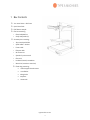
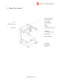
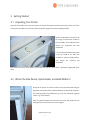
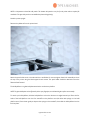
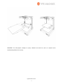
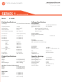
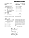
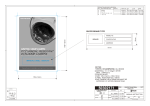
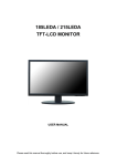
SERIES 1 USER MANUAL TYPE A MACHINES Type A Machines Inc. ©2014 Type A Machines Inc. This document is licenced by Creative Commons Attribution-NonCommercial-ShareAlike (CC BY-NC-SA) Users are free to remix, tweak, and build upon this work for non-commercial use, as long as users credit Type A Machines Inc. and license their new creations under the identical terms. Every effort has been made to ensure that the information contained in this manual is accurate. Type A Machines is not responsible for printing or clerical errors. Type A Machines 926 Howard St. San Francisco, CA 94103 www.typeamachines.com Products in this manual may be covered by US and International Patents. Type A Machines is a registered trademark of Type A Machines Inc. Any products names mentioned in this manual are the property of their respective parties. V1.1 08.02.14 2014 Series 1 User Manual | Version 1.2 2014 Series 1 3D Printer User Manual Welcome to the Type A Machines family of creators. We’re excited about helping professionals, educators and individuals like yourself create amazing things that support your success. This user manual will help you get up and running quickly. You will also find resources online to dive in more deeply, applications to build and print your own 3D models, and models to download. Enabling you to go from idea to physical object is our goal. We encourage you to share your creations and give us input online at: http://forum.typeamachines.com/ We can’t wait to see what you create. Happy printing! Espen Sivertsen, CEO Type A Machines typeamachines.com 0 2014 Series 1 User Manual | Version 1.2 Contents 1 Box Contents .................................................................................................................................. 2 2 About Your Series 1 ....................................................................................................................... 3 3 Getting Started ............................................................................................................................... 4 3.1 Unpacking Your Printer ........................................................................................................ 4 3.2 Attach the Side Panels, Spool Holder, and Build Platform .............................................. 4 3.3 Connect to Ethernet and Power On ................................................................................... 8 3.4 Load Filament ........................................................................................................................ 7 3.5 Connect to the Web Interface ............................................................................................. 8 3.6 Verifying and Calibrating the Z Height ............................................................................... 9 3.7 Verifying Build Platform Alignment .................................................................................. 11 3.8 Apply the Build Surface Treatment................................................................................... 11 3.9 Time to Test Print! ............................................................................................................... 11 4 Wi-Fi Set Up .................................................................................................................................. 13 5 Software Setup............................................................................................................................. 13 5.1 Slicing software.................................................................................................................... 14 5.2 Loading a GCode File .......................................................................................................... 14 6 Removing a Printed Object from the Print Surface ................................................................ 15 7 Prepare for Your Next Print ....................................................................................................... 15 8 File Type Basics: .STL and GCode .............................................................................................. 15 9 Customer Support ....................................................................................................................... 16 typeamachines.com 1 2014 Series 1 User Manual | Version 1.2 1 Box Contents Your 2014 Series 1 3D Printer Quick Start Guide PLA filament sample Flat box containing: o Glass build platform o Acrylic side panels (4) Accessory box containing: o 3D printed spool holder o Spool holder L-bracket o Power cable o Ethernet cable o Wi-Fi antenna o Spatula for print removal o Glue stick o Insulated (ceramic) screwdriver o Wrench kit (contains 2 wrenches) Plastic bag containing: 2 black-topped thumb screws 4 small bolts 8 large bolts 8 spacers Hex wrench typeamachines.com 2 2014 Series 1 User Manual | Version 1.2 2 About Your Series 1 typeamachines.com 3 2014 Series 1 User Manual | Version 1.2 3 Getting Started 3.1 Unpacking Your Printer Open the box and tilt it over so that the printer is on its back. Grasp the metal arms where they connect to the rest of the printer, and slide it out of the box. Stand the printer upright to remove the packing material. Raise the build platform several inches by turning the white knob, located in the top-middle of the build area, then remove the accessories box held underneath. Turn the 3D printed white knob located in the top middle of the build area clockwise to raise the build platform, then remove the accessory box underneath. Now check the contents of the printer box to make sure that your 2014 Series 1 3D Printer shipped with all its parts. 3.2 Attach the Side Panels, Spool Holder, and Build Platform Gently lay the printer on its back to attach the acrylic side panels using the large bolts and spacers, which are placed between the side panel and printer. The panels engraved “Type A Machines” go on the top. The panels engraved “Series 1” go on the bottom. Place the spacers between the printer and the acrylic side panels and use the large bolts to hold in place. Do not over-tighten. typeamachines.com 4 2014 Series 1 User Manual | Version 1.2 NOTE: It is important to install the side panels. The bottom side panels act as feet for the printer and are required for ventilation. The upper side panels act to stabilize the printer during printing. Stand the printer upright. Remove the yellow tie from the printer head. Attach the spool holder to the L-bracket with the 4 small bolts. Do not over tighten. Attach the assembly to the to the top of the printer using the black topped thumb screws. The spool holder should be attached so that the filament feeds forward. The build platform is a glass build plate attached to an aluminum platform. NOTE: The glass build plate can be affected by oils on your fingertips, so avoid touching the surface unnecessarily. To attach your build platform, hold the build platform so that the aluminum is angled toward you. Place the four holes of the build platform onto the four standoffs on the platform arms (the bolts with springs on the build platform arms). Press down gently to depress the springs on the standoffs, then slide the build platform back to lock into place. typeamachines.com 5 2014 Series 1 User Manual | Version 1.2 IMPORTANT: The build platform standoffs are factory calibrated and should not need to be adjusted unless troubleshooting indicates it is necessary. typeamachines.com 6 2014 Series 1 User Manual | Version 1.2 3.3 Load Filament Place a spool of filament onto the spool holder. Trim the end of the filament to ensure a clean, straight end. Press and hold the lever on the right side of the print head to move the roller at the top of the lever to expose the hole the filament goes into. Insert the filament into the hole until it meets resistance, approximately the depth of the print head, then release the lever. NOTE: Not all filament is created equal. Please be aware that the quality of PLA can vary substantially. Poor quality PLA may damage your 2014 Series 1 3D Printer and it will interfere with your ability to create a successful print. High quality filament is available through the Type A Machines online store: www.typeamachines.com/products typeamachines.com 7 2014 Series 1 User Manual | Version 1.2 3.4 Connect to Ethernet and Power On Your printer comes with two methods of connection: Ethernet (connecting to a router or base station) and wireless (Wi-Fi) networking. For initial set up you must use an Ethernet connection. Attach the power cord and Wi-Fi antenna, then connect the printer via Ethernet cable to your router or Wi-Fi base station. Ensure that the button on the front panel is not depressed, then turn on the power using the power switch on the back of the printer. Before powering on your new printer, the Ethernet cable must be connected to the printer and either a router or Wi-Fi base station in order for the printer to configure its network. IMPORTANT: To stop all printer activity immediately, depress the lit button on the front panel of your Series 1 printer. To begin using your printer again, press the button again to return it to its normal state. Then click the Connect button in your printer’s web interface (read more below) to resume using your printer. 3.5 Connect to the Web Interface If you are a Windows user, you must download Bonjour Print Services to connect your PC to the Series 1. If you are a Mac user or your PC has iTunes installed, you can skip this step—your PC already has it. To access the printer’s web interface, open a web browser on your computer and enter series1-XXXX.local:5000, as shown below. Use the last 4 digits of the serial number engraved on the face of your 2014 Series 1 3D Printer in place of XXXX. NOTE: It may take several minutes for your printer’s web interface to load the first time or after a restart. typeamachines.com 8 2014 Series 1 User Manual | Version 1.2 The printer’s web interface is shown above. If your printer has not connected to its web interface after 5 minutes, try connecting again. First turn off the power, next check that the Ethernet cable is connected correctly, and then turn on the power again and wait a few minutes for the printer to establish a connection. 3.6 Verifying and Calibrating the Z Height The 2014 Series 1 3D printer features a black Z height adjustment knob, shown left, at the top right of the build area. That knob is used to increase or decrease the distance between the print head nozzle and the build surface for the first layer of a print. The Z height adjustment knob works by triggering a microswitch mounted to the build platform arms. It is adjusted in the factory so that the typeamachines.com 9 2014 Series 1 User Manual | Version 1.2 switch is triggered when the build surface is just below the tip of the print head nozzle. CAUTION: Before checking the Z height, make sure the print head is cool. Failure to ensure the print head is cool may result in damage to the machine. Setting the build platform home position determines the distance from the build platform to the print head. To verify that it is set correctly, open your printer’s web interface (shown above), click the Control tab, use the X/Y buttons to move the print head to the middle of the build platform, then click the Z Home button to move the build platform to the home position. When set correctly, the tip of the print head nozzle should just touch, but should not put pressure on the build platform. If the build platform home position is not set correctly, rotate the black knob one quarter turn, then click the Z Home button again to move the build platform to the new home position. Turn the black knob clockwise to move the build platform farther from the print head and counterclockwise to move it closer. Each time you adjust the Z height knob, click the Z Home button again. Repeat the process until the print head nozzle just touches the surface. typeamachines.com 10 2014 Series 1 User Manual | Version 1.2 3.7 Verifying Build Platform Alignment The build platform is calibrated to be parallel to the print head during manufacturing, but shifting may occur during shipping. Use the X and Y buttons on the Control tab of the web interface to move the print head to each corner of the build surface to verify your build platform is aligned with the print head. If not, see “Aligning the Build Platform” in the Troubleshooting section of the Type A Machines web page. 3.8 Apply the Build Surface Treatment The glass square is your build surface. In order to prepare the surface for printing, open the included glue stick and apply a thin layer across the platform. Allow the glue to dry to the touch before printing. You may be able to print several times before replacing the build surface treatment. At some point, however, portions of the printed object will no longer stick to the surface. When this happens, rinse the dried glue from the build surface, let it dry, and reapply the glue using the included glue stick. You may wish to vary your level of adhesion based on your print type. For general use the included glue stick works well. For more delicate prints, stronger adhesion, or easier removal, try 3M 2093-EL 2” wide blue painter’s tape. To use blue painter’s tape, cut a length of tape about 12 inches long, align it with the bottom of the glass build surface. Place each subsequent length of tape edge to the edge along side the tape already placed on the build surface. Do not overlap the tape. Repeat this process until the glass build surface is covered with tape. Use the print removal spatula to ensure there are no bubbles or voids. Avoid touching the tape where you will be printing as the oils from your fingers may affect adhesion. 3.9 Time to Test Print! Choose the file “FirstPrint.gcode” from the files at the bottom left of the printer’s web interface. All files listed there are included with your printer. Click the Print icon to the right of the file you select. Your printer will upload the file and will begin printing. Click on the Temperature tab (shown below) in the web interface to watch as the print head heats up. Be patient as this will take a few seconds. typeamachines.com 11 2014 Series 1 User Manual | Version 1.2 CAUTION: The print head is hot and you may burn yourself if you touch it or newly extruded filament. If your GCode is set to extrude filament prior to starting the print, you can manually remove this extra filament with the print removal spatula, or allow it to be wiped off on the build surface. The print head will then begin creating your print. The front fan will remain off while printing the first few layers. The fan should turn on later to help solidify the printed part. The rear fan is always on when the print head is above 50˚ Celsius. typeamachines.com 12 2014 Series 1 User Manual | Version 1.2 It’s a good idea to closely examine the first layer as it prints. This is the most critical part of the print. The extruded filament should spread onto the print surface and adhere to it. It should not be stringy nor should it be crushed into the surface. If you have a problem with adhesion or extrusion, try resetting the Z height, retest the build platform alignment, and change the surface treatment. 4 Wi-Fi Set Up Once initial set up is done using Ethernet, you can connect to your printer via Wi-Fi. If you have not already, attach the Wi-Fi antenna to the back of the printer by screwing it on. It is a good idea to set your printer up in the same room as your wireless base station for the first connection. Once you have it working you can move the printer to your desired location and then test to make sure the printer is still within WiFi range. In the printer’s web interface click “Settings” in the top right of the window, then click “Network” at the bottom of the page. Enter or select your Wi-Fi network in the “SSID (Network Name)” field. If a password is required, type your Wi-Fi password into the password field. You can now connect to your printer’s web interface using the same URL you entered initially when connecting via Ethernet. 5 Software Setup typeamachines.com 13 2014 Series 1 User Manual | Version 1.2 5.1 Slicing software To begin printing your own designs to your 2014 Series 1 3D Printer you will need to install a slicing engine. This is the program that takes the model information from your CAD program and converts it into machine readable code (also known as GCode) to tell the printer what to do. There is a slicer software installation package with settings for your 2014 Series 1 3D Printer embedded and additional test models that are available for download on our website. Select the link for the Operating System you are running and download. Go to typeamachines.cm/download to get your installer package. 5.2 Loading a GCode File Your printer ships pre-loaded with sliced models to get you up and running. To load one of the supplied GCode files, click the Load button in the “Files” section of your printer’s web interface. Select any of the premade GCode files. If you have another GCode file sliced and saved on your computer, then click the Upload button to select it and load it onto your printer. NOTE: The web interface will accept STL files but it will not allow you to print them, so make sure your uploaded file is a GCode file. After the file is loaded you will see a status appear in the “State” section above the “Files” section. Click on the Print button to start printing. Keep in mind that larger GCode typeamachines.com 14 2014 Series 1 User Manual | Version 1.2 files will take longer to upload. 6 Removing a Printed Object from the Print Surface When your 3D print completes, the print head will move to the back of the machine. Most of the time you will be able to gently pry your print off the surface using the included print removal spatula. If your finished part does not come off easily, after the machine has cooled you can quickly and easily take out the build platform to remove the printed object. This is particularly useful for prints with a large footprint. To do this, first grasp the sides of the build platform. Press down gently to depress the standoff springs, then gently slide the build platform towards you to detach it from the bolts. Once the build platform has been removed from the machine, it is easier to work the print removal spatula all the way around the printed object in order to separate it from the build platform. If your printed object will not separate from the build platform, take it to a sink and run warm water around the print to loosen the glue. Use the print removal spatula to work warm water under the print. Once your print is loose, you should be able to gently pull the rest of it off of the print surface. NOTE: This water method of print removal should be used instead of applying force, which may crack the glass on the build platform. Be patient and let the warm water work. If you crack the glass a replacement can be ordered from the accessories area of the typeamachines.com web store. 7 Prepare for Your Next Print You may be able to print multiple times before your surface treatment will need to be replaced. In order to promote good adhesion of the initial print layer, avoid touching the build surface with your fingers so as not to transfer oils to the build surface. If subsequent prints do not attach to the print surface well, replace the build surface treatment. 8 File Type Basics: .STL and GCode The first step in the process from your 3D model to making a 3D print is to export your 3D model from your modeling program as an .STL file. STL is an industry standard for 3D printing files. Your model must be a closed, typeamachines.com 15 2014 Series 1 User Manual | Version 1.2 water-tight mesh. This is critical to producing a quality print. There are many software modeling tools and mesh repair utilities you can use for this. We have included a few premade GCode files on your printer and also in the slicer download package so you can get printing right out of the gate. The 2014 Series 1 3D Printer reads instructions about how to move the print head and build platform and when to extrude filament from a file called a GCode file. GCode is produced by “slicing” software. GCode files end in “.gcode” or “.gco.” GCode files are specific for each type of printer. When you slice a 3D file, you need to make sure that your slicer software is using settings specifically for the 2014 Series 1 3D Printer. Otherwise the resulting GCode will not communicate correctly to your printer. 9 Customer Support If you’re having trouble getting a print to run smoothly, or you haven’t been able to find answers to your questions in this manual, the next place to look is at the videos and knowledge base articles found in our product support area at www.support.typeamachines.com/hc/en-us. If you do not find what you need there, please visit our community forum at www.forum.typeamachines.com. Type A Machines is privileged to have an active, well informed, and helpful community on our forums. The forum is also one of our favorite places to announce product giveaways, betas, and competitions. Finally, it’s also a great place for you to show off your awesome prints and machine modifications. Enjoy your new printer and welcome to the Type A Machines community! typeamachines.com 16 www.typeamachines.com [email protected] +1(415) 371-9682 TYPE A MACHINES SERIES 1 Model: 2014 SPECIFICATIONS S114SA2 Printing Specifications Technology: FFF (Fused Filament Fabrication) Filament Diameter: 1.75mm Hot End Type: Nozzle Diameter: Hot-End Max Temperature: SINGLE PIECE 0.4mm 275°C (527°F) Build volume: 1728 in3 (28.37 liters) Build AreaX: Build Area Y: Build Area Z: 12.0” (305mm) 12.0” (305mm) 12.0” (305mm) Layer Resolution: Final50 Micron High 100 Micron Normal 150 Micron Low 200 Micron Draft 250 Micron Positional Accuracy: X/Y: 6.67 Microns Z: 6.25 Microns Print Speed: 50-150mm/s Travel Speed: 150-250 mm/s Physical Specifications: Overall Width:18.35” (765.75mm) Height:22.51” (571.80mm) Depth:18.05” (458.67mm) Machine Weight: 30lbs (13.60kg) With Spool of PLA and holder attached Width:18.35” (765.75mm) Height:31.55” (801.48mm) Depth:20.98” (533.02mm) Shipping Box: Width:24” (609.6mm) Height:24” (609.6mm) Depth:24” (609.6mm) Shipping Weight: 35lbs (15.87kg) Software Specifications Slicing Software: Supported Packages: Cura for Type A Machines Supported file types: STL, OBJ, AMF OS: Windows 32/64 Bit Vista/7/8 Linux: 32/64 Bit (Ubuntu 12.04+) Mac OS X 10.6+ Control Software Series 1 Octoprint (included) File type: .GCODE .GCO Processor 1 Ghz ARM Linux Processor 8GB+ expandable onboard Storage Connectivity Device port: Expansion ports: 1x USB ‘B’ 2x USB ‘A’ + USB expansion bus Wifi:B/G/N 1Ghz WiFi Security: WEP/WPA/WPA2 100MB Ethernet Operation Envelope Operating Voltage: 110-240 VAC Internal Voltage: 24 VDC/5VDC Operating Temperature: 60-99°F (15-37°C) Operating Humidity: 5-95% Storage Humidity: 5-95% Storage Temp:32-99°F(0-37°C) Operation Noise: 40-70 dB