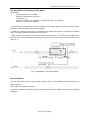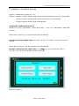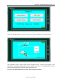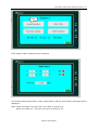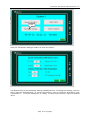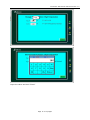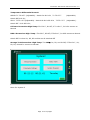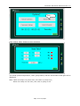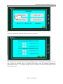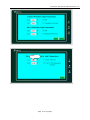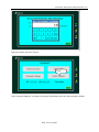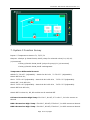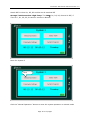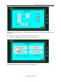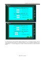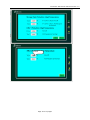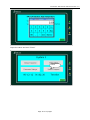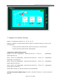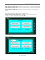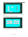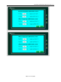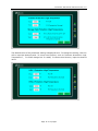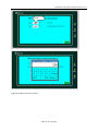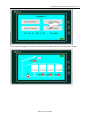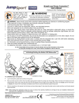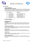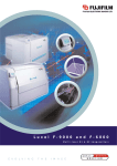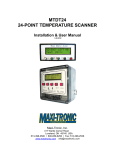
1
Controller Instruction Manual Version 1.0
eco Hybrid Solar
Contoller CA5J
User’s Manual
Page 1 of 34 pages
Controller Instruction Manual Version 1.0
Thank you for purchasing the eco Hybrid Solar Controller CA5-J.
Please read through this manual carefully and completely in order to operate
this controller at its best possible performance.
CONTENTS
1. General Instructions ............................................ 3
2. Technical Data ...................................................... 3 3. Installation and Wiring ........................................ 4 4. Touch Screen ..................................................... 5 5. System Function 1 …………………………………………………… 7 6. System Function 2 .......................................... 613 7. System Function 3 .......................................... 206 8. System Function 4 .......................................... 276
Page 2 of 34 pages
Controller Instruction Manual Version 1.0
1. General Instructions
These Installation and operating instructions contain important information and basic
instructions .Please read the following information carefully before installing and operating
the controller.
- Only qualified technicians are recommended to install and operate this controller. Please
get familiar with all the safety regulations and operating instructions before commissioning
the controller into service.
- This controller shall be operated with the correct power supply.
- This controller shall work within the scope of the technical data provided.
- Do not mount the controller in a location of high humidity or the possibility of water
infiltration.
- Do not mount the controller in the vicinity of hazardous or corrosive material.
- The controller can only be used as per the listed functions; unauthorized modifications or
installing additional components not provided or recommended may cause damage to the
controller.
- The wiring connections need to be followed as per the diagrams in this manual, incorrect
wiring connections may cause damage to the controller and the devices driven by this
controller.
- Any modifications to the unit are not permitted without the written permission from
eco Hybrid Solar, LLC.
2. Technical Data
Power Supply: 24VAC, 60Hz
Self-Consumption: < 20W
Temp. Sensor Precision:±1℉
Temp. Sensor Type:PT100
Total Output Power: 8kW
5 Relays Designated
: 24VAC, 200W
7) 1 Relay Undesignated : 24VAC, 200W
8) Rated Operating Leakage Current: 30mA/0.1S
9) Dimensions: 500×400×155mm
10) Installation Location: Indoors
11) Ambient Temperature: 32~130℉
12) Humidity: <85%
1)
2)
3)
4)
5)
6)
Page 3 of 34 pages
Controller Instruction Manual Version 1.0
3. Installation and Wiring
The controller shall be wall-mounted in a location not
susceptible to water damage and high humidity.
3.1 Mounting
The controller must be located indoors.
1. Locate the controller where it can be safely operated,
drill four holes and attach M8 expansion bolts with a
length of 17.7 inches and a width of 13 inches, see
Fig.1.
2. Attach the controller with the enclosed screws (M6)
and hangers
3.2 Wire Connections
Fig. 2 Wire Connections
Inputs:
- 5 temperature sensors to be connected as Fig. 2.
- use 0.2~0.5mm2 thick 3-wire shielded cable to connect all temperature sensors;
- thermometer power: use 0.5mm2 thick 2-wire armored cable
- Thermometer COM: communication
0.2~0.5mm2 thick 2-wire shielded cable.
between
thermometer
and
controller,
use
Note: attention on the wire color when connecting temp. sensors on terminals, it is White,
Red and White color cable from left to right, do not reverse.
Outputs:
- use 1mm2 2-wire armored cable to connect pump P1 and/or valves R1, R2, R3 and R4 at
24VAC;
- if pump and/or valves are not 24V powered, use a relay between controller and loads;
- make water proof treatment for all cables.
Page 4 of 34 pages
Controller Instruction Manual Version 1.0
3.3 Installation of Ultrasonic Flow Meter
Flow Meter:
- Working pressure <1.0Mpa
- Working temperature:39~203℉
- Connector: 1”
- Flow rate range: 0.3~30gal/min, rated flow rate: 15.4gal/min
- Battery: 3.6V lithium battery
- Remove any contaminants from the surface of the copper pipes where the meter is to be
located in order to avoid inaccurate readings.
- Install the ultrasonic flow meter, including all the components where no exposure to water,
frost, chemicals and EMC interference can occur.
- Ensure the arrow direction on the flow meter is the same as the water flows; make sure
there is 6-12 inches of straight pipe before the flow meter and 4-6inch after the flow meter
see Fig. 3.
Fig. 3 Installation of the Flow Meter
BTU calculation
Use the Flow meter (with 2 extra temp. sensors T6 & T7) to calculate the heat gain of the
whole system.
Flow meter is a DN25 connector;
Controller reads the heat gain from the Flow meter and will display the final accumulative
heat gain.
Page 5 of 34 pages
Controller Instruction Manual Version 1.0
4. Touch Screen
Start Page
Click the button “Enter” to enter the system selection.
System selection: Click the system schematics to choose the system; Only one system can
be selected; The system with a green lamp is the selected one
Page 6 of 34 pages
Controller Instruction Manual Version 1.0
5. System 1 Function Survey
Inputs: 5 Temperature Sensors T1, T2
Outputs: 4 Relays @ 24VAC 200W, 60HZ (relays for solenoid valves) R1, R2 (L, N terminal)
1 Relay @ 24VAC 200W, 60HZ (relays for pump) P1 (L,N terminal)
1 Relay @ 24VAC 200W, 60HZ undesignated
Temperature Differential Control:
SOLAR T1-T2>45℉ (Adjustable),Switch On R1 & P1;T1-T2<37℉ (Adjustable), Switch Off
R1 & P1;
Switch off P1 when R1, R2, R3 and R4 are all switched Off.
Collector Protection:High-Temp.:T1≥230℉, R1 Off; if T1≤210℉, P1 & R1 resume to
Normal
Switch Off P1 when R1, R2, R3 and R4 are all switched Off
Storage Tank Protection: High-Temp. T2≥140℉, R1, R2, R3, R4 and P1 Off; if
T2≤130℉, R1, R2, R3, R4 and P1 resume to Normal
Menu for System 1
Page 7 of 34 pages
Controller Instruction Manual Version 1.0
Click the “Manual Operation” button to enter the system operation in manual mode.
Press
The Controller is now in manual mode once this page is shown. Click the load symbol on the
schematic to activate/deactivate pump or valve. When the device is on, the light displays a green
color, and then changes to a red color when the device is off.
Upon exit of the Manual Mode the controller will activate the Auto Mode.
Page 8 of 34 pages
Controller Instruction Manual Version 1.0
Click
Click “Status Table” button to show as below:
The actual system temperature, valve, pump status, and the accumulative heat gain will be
displayed.
Note: When the lamp is a green color, the valve or pump is on;
When the Lamp is a red color, the valve or pump is off.
Page 9 of 34 pages
Controller Instruction Manual Version 1.0
Click
Click the “Parameter Settings” button to show the status:
The default value of the parameter setting is displayed here. To change the setting, click the
cell to input the desired value. To cancel one function, such as “Collector Protection: High
Temperature”, T1>230F change into T1>999F; To resume this function, input the desired
value.
Page 10 of 34 pages
Controller Instruction Manual Version 1.0
Click
Input the value and click “Enter”
Page 11 of 34 pages
Controller Instruction Manual Version 1.0
Click
Click “System Diagram” to show the system schematics and real-time operation status.
6. System 2 Function Survey
Inputs: 5 Temperature Sensors T1, T2,T3
Outputs: 4 Relays @ 24VAC 200W, 60HZ (relays for solenoid valves) R1, R2,
(L,N terminal)
1 Relay @ 24VAC 200W, 60HZ (relays for pump) P1 (L,N terminal)
1 Relay @ 24VAC 200W, 60HZ undesignated
Page 12 of 34 pages
Controller Instruction Manual Version 1.0
Temperature Differential Control:
SOLAR T1-T2>45℉ (Adjustable),Switch On R1 & P1;T1-T2<37℉
(Adjustable),
Switch Off R1 & P1;
HRU 1 T3-T2>45℉(Adjustable),Switch On R1 & R2 & P1;T3-T2<37℉
(Adjustable),
Switch Off R1 & R2 & P1;
Collector Protection:High-Temp.:T1≥230℉, R1 Off; if T1≤210℉, P1 & R1 resume to
Normal
HRU 1 Protection: High-Temp.: T3≥230℉, R2 Off; if T3≤210℉, P1 & R2 resume to Normal
Switch Off P1 when R1, R2, R3 and R4 are all switched Off
Storage Tank Protection: High-Temp. T2≥140℉, R1, R2, and P1 Off; if T2≤130℉, R1,
R2, R3, R4 and P1 resume to Normal
Menu for System 2
Page 13 of 34 pages
Controller Instruction Manual Version 1.0
Click
Click the “Manual Operation” button to enter the system operation in manual mode
Press
The Controller is now in manual mode once this page is shown. Click the load symbol on the
schematic to activate/deactivate pump or valve. When the device is on, the light displays a green
color, and then changes to a red color when the device is off.
Upon exit of the Manual Mode the controller will activate the Auto Mode.
Page 14 of 34 pages
Controller Instruction Manual Version 1.0
Click
Click “Status Table” button to show as below:
The actual system temperature, valve, pump status, and the accumulative heat gain will be
displayed.
Note: When the lamp is a green color, the valve or pump is on;
When the Lamp is a red color, the valve or pump is off.
Page 15 of 34 pages
Controller Instruction Manual Version 1.0
Click
Click the “Parameter Settings” button to show the status:
The default value of the parameter setting is displayed here. To change the setting, click the
cell to input the desired value. To cancel one function, such as “SOLAR Temperature
Differential Control”, T1-T2>45F change into T1-T2>999F; To resume this function, input
the desired value.
Page 16 of 34 pages
Controller Instruction Manual Version 1.0
Click
Page 17 of 34 pages
Controller Instruction Manual Version 1.0
Input the value and click “Enter”
Click
Click “System Diagram” to show the system schematics and real-time operation status.
Page 18 of 34 pages
Controller Instruction Manual Version 1.0
7. System 3 Function Survey
Inputs: 5 Temperature Sensors T1, T2,T3,T4
Outputs: 4 Relays @ 24VAC 200W, 60HZ (relays for solenoid valves) R1, R2, R3,
(L,N terminal)
1 Relay @ 24VAC 200W, 60HZ (relays for pump) P1 (L,N terminal)
1 Relay @ 24VAC 200W, 60HZ undesignated
Temperature Differential Control:
SOLAR T1-T2>45℉ (Adjustable),Switch On R1 & P1;T1-T2<37℉ (Adjustable),
Switch Off R1 & P1;
HRU 1 T3-T2>45℉(Adjustable),Switch On R1 & R2 & P1;T3-T2<37℉(Adjustable),
Switch Off R1 & R2 & P1;
HRU 2 T4-T2>45℉(Adjustable),Switch On R1 & R3 & P1;T4-T2<37℉(Adjustable),
Switch Off R1 & R3 & P1;
Switch Off P1 when R1, R2, R3 and R4 are all switched Off.
Collector Protection:High-Temp.:T1≥230℉, R1 Off; if T1≤210℉, P1 & R1 resume to
Normal
HRU 1 Protection: High-Temp.: T3≥230℉, R2 Off; if T3≤210℉, P1 & R2 resume to Normal
HRU 2 Protection: High-Temp.: T4≥230℉, R3 Off; if T4≤210℉, P1 & R3 resume to Normal
Page 19 of 34 pages
Controller Instruction Manual Version 1.0
Switch Off P1 when R1, R2, R3 and R4 are all switched Off
Storage Tank Protection: High-Temp. T2≥140℉, R1, R2, R3, R4 and P1 Off; if
T2≤130℉, R1, R2, R3, R4 and P1 resume to Normal
Menu for System 3
Click
Click the “Manual Operation” button to enter the system operation in manual mode
Page 20 of 34 pages
Controller Instruction Manual Version 1.0
Press
The Controller is now in manual mode once this page is shown. Click the load symbol on the
schematic to activate/deactivate pump or valve. When the device is on, the light displays a green
color, and then changes to a red color when the device is off.
Upon exit of the Manual Mode the controller will activate the Auto Mode.
Click
Click “Status Table” button to show as below:
Page 21 of 34 pages
Controller Instruction Manual Version 1.0
The actual system temperature, valve, pump status, and the accumulative heat gain will be
displayed.
Note: When the lamp is a green color, the valve or pump is on;
When the Lamp is a red color, the valve or pump is off.
Click
Click the “Parameter Settings” button to show the status:
Page 22 of 34 pages
Controller Instruction Manual Version 1.0
The default value of the parameter setting is displayed here. To change the setting, click the
cell to input the desired value. To cancel one function, such as “Collector Protection: High
Temperature”, T1>230F change into T1>999F; To resume this function, input the desired
value.
Page 23 of 34 pages
Controller Instruction Manual Version 1.0
Click
Page 24 of 34 pages
Controller Instruction Manual Version 1.0
Input the value and click “Enter”
Click
Page 25 of 34 pages
Controller Instruction Manual Version 1.0
7. System 4 Function Survey
Inputs: 5 Temperature Sensors T1, T2, T3, T4, T5
Outputs: 4 Relays @ 24VAC 200W, 60HZ (relays for solenoid valves) R1, R2, R3, R4
(L,N terminal)
1 Relay @ 24VAC 200W, 60HZ (relays for pump) P1 (L,N terminal)
1 Relay @ 24VAC 200W, 60HZ undesignated
Temperature Differential Control:
SOLAR T1-T2>45℉ (Adjustable),Switch On R1 & P1;T1-T2<37℉
(Adjustable),
Switch Off R1 & P1;
HRU 1 T3-T2>45℉(Adjustable),Switch On R1 & R2 & P1;T3-T2<37℉
(Adjustable),
Switch Off R1 & R2 & P1;
HRU 2 T4-T2>45℉(Adjustable),Switch On R1 & R3 & P1;T4-T2<37℉
(Adjustable),
Switch Off R1 & R3 & P1;
HRU 3 T5-T2>45℉(Adjustable),Switch On R1 & R4 & P1;T5-T2<37℉
(Adjustable),
Switch Off R1 & R4 & P1;
Switch Off P1 when R1, R2, R3 and R4 are all switched Off.
Collector Protection:High-Temp.:T1≥230℉, R1 Off;if T1≤210℉, P1 & R1 resume to
Normal
Page 26 of 34 pages
Controller Instruction Manual Version 1.0
HRU 1 Protection: High-Temp.: T3≥230℉, R2 Off; if T3≤210℉, P1 & R2 resume to Normal
HRU 2 Protection: High-Temp.: T4≥230℉, R3 Off; if T4≤210℉, P1 & R3 resume to Normal
HRU 3 Protection: High-Temp.: T5≥230℉, R4 =Off; if T5≤210℉, P1 & R4 resume to
Normal
Switch Off P1 when R1, R2, R3 and R4 are all switched Off
Storage Tank Protection: High-Temp. T2≥140℉, R1, R2, R3, R4 and P1 Off; if
T2≤130℉, R1, R2, R3, R4 and P1 resume to Normal
Menu for System 4
Click
Page 27 of 34 pages
Controller Instruction Manual Version 1.0
Click the “Manual Operation” button to enter the system operation in manual mode.
Press
The Controller is now in manual mode once this page is shown. Click the load symbol on the
schematic to activate/deactivate pump or valve. When the device is on, the light displays a green
color, and then changes to a red color when the device is off.
Upon exit of the Manual Mode the controller will activate the Auto Mode.
Click
Click “Status Table” button to show as below:
Page 28 of 34 pages
Controller Instruction Manual Version 1.0
The actual system temperature, valve, pump status, and the accumulative heat gain will be
displayed.
Note: When the lamp is a green color, the valve or pump is on;
When the Lamp is a red color, the valve or pump is off.
Click
Click the “Parameter Settings” button to show the status:
Page 29 of 34 pages
Controller Instruction Manual Version 1.0
Page 30 of 34 pages
Controller Instruction Manual Version 1.0
The default value of the parameter setting is displayed here. To change the setting, click the
cell to input the desired value. To cancel one function, such as “Collector Protection: High
Temperature”, T1>230F change into T1>999F; To resume this function, input the desired
value.
Page 31 of 34 pages
Controller Instruction Manual Version 1.0
Click
Input the value and click “Enter”
Page 32 of 34 pages
Controller Instruction Manual Version 1.0
Click
Click “System Diagram” to show the system schematics and real-time operation status.
Page 33 of 34 pages
Controller Instruction Manual Version 1.0
Click
Click Time to calibrate the Time, Date and Operating Hours
Page 34 of 34 pages