1
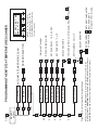
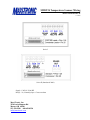
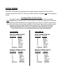
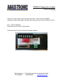
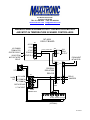
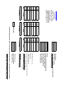
MTDT24
24-POINT TEMPERATURE SCANNER
Installation & User Manual
5-30-2012
Maxi-Tronic, Inc.
:DUGV&RUQHU5RDG
Loveland, OH 45140 USA
513-398-2500 / 800-659-8250 / Fax: 513-398-2536
www.maxitronic.com [email protected]
OVERVIEW:
The MTDT24 is a microprocessor-based temperature controller which will scan, display and
actuate alarms for up to 24 thermocouple sensors. High-Temperature Limit and Rate-of-Rise
alarm set points are easily configured and each can activate the 5A SPST (N/O or N/C) relay. An
RS232 or RS485 option is available for remote operation up to 2000 feet away using wire and
over 2 miles for the wireless connection option. The MTDT24 is fully compatible with the
computerized MaxiTrack remote monitoring system providing data archiving and email and cellphone alarm notifications.
DISPLAY:
The 16 character display shows the sensor number, the sensor ID (if programmed), current
temperature, alarm enabled status, and any activated alarms.
“*” indicates the alarm for this sensor number is enabled
“F” indicates a High-Temperature alarm for the sensor number listed.
“R” indicates a Rate-of-Rise alarm for the sensor number listed.
EX.: In this example sensor #20 is labeled “DRY LEG HD L”, it is reading 83F and its alarm is
enabled(*). Also, both High-Temperature and Rate-of-Rise alarms are tripped on sensor #24:
20:DRY LEG HD L
Temp: 083F* FR24
If a sensor name is not programmed, the sensor’s ID number (1 through 24) is displayed.
SENSOR INPUT:
This unit only accepts ungrounded Type “T” thermocouple (Copper/Constantan) input.
You must use Type “T” thermocouple leadwire (extension wire) when connecting all sensors
to this unit. Do not use plain copper wire when running sensors to the MTDT24 scanner.
Proper polarity must be observed when making thermocouple connections. There are silver
colored Constantan (common) conductors and a copper colored Copper conductors.
The unit will not function correctly if plain copper wire is used
or if proper thermocouple polarity is not observed.
Sensor input connector: 25 Pin D-Sub type socket:
Connect the Copper (-) leads coming from the sensors to inputs #1 through #24.
All Constantan (+) leads should be joined and connected to input #25.
All unused inputs should be jumpered to pin 25.
(female socket view)
13
25
1
14
Type “T” Thermocouples:
Copper leads: #1-24,
All Constantan leads: #25
See the Pigtail Wiring section at the back of this manual for further wiring instructions.
Note: A broken thermocouple will typically read 230F.
INPUT POWER:
Input power should not be applied until all thermocouple sensor inputs have been connected!
Connect 115 VAC* input voltage to terminals #1 and #2. For wall mount units, these will be the
two terminals closest to the internal transformer. Units are factory set up for 115VAC input voltage,
*contact Maxi-Tronic for a 230VAC model.
The RS-485 output is fully compatible with MaxiTrack remote monitoring system providing data
archiving, and email and cell-phone alarm notifications.
Note: If this unit is being used within a Maxi-Tronic multi-monitor control housing the input power
will be pre-wired.
TRIP #1 (F) = High Temperature Alarm
TRIP #2 (R) = Rate-of-Rise Alarm
RELAY OUTPUTS:
Relay contacts are rated at 5 amps @117VAC, SPST, N/O or N/C user selectable. Scanners are
set for N/O relay operation at the factory.
High-Temperature alarm (F) relay output is located on terminals #5 and #6. If this is being used
within a Maxi-Tronic multi-monitor, this will be pre-wired for a common alarm output (typically
through DIN-rail isolation relays) with other Maxi-Tronic controls.
Rate-of-Rise alarm (R) relay output is located on terminals #3 and #4 on the terminal strip.
SYSTEM TESTING:
Disconnect a sensor wire and the scanner should sound the alarm and display the sensor number.
A display of 230F indicates a broken (open) thermocouple sensor wire.
SYSTEM CONFIGURATION
After making any configuration changes to the MTDT24, you should cycle the power (off for a
couple seconds then back on) of the MTDT24 to reset it.
The following options are available through the MTDT24 menu system:
SCAN RATE:
The sensor scan rate is adjustable from 1.0 to 4.0 seconds per sensor.
The Scan option is selectable for Automatic scanning or Manual operation.
ALARM OPERATION:
Each sensor’s alarm can be enabled or disabled. An asterisk will display next to each sensor’s
temperature reading when its alarm is enabled. Ex.: 24: Temp: 073F*
High-Temperature alarm:
The High-Temperature alarm setpoint is the same for all sensors. If you want the High-Temperature
alarm to activate at 140°F, then all sensors will alarm at that point. If the High-Temperature setpoint is reached on a sensor, an “F” will display along with the sensor number that tripped the
alarm. Example: F 24
NOTE: Relay #1 will remain tripped until the temperature falls back below the alarm set-point.
Rate-of-Rise alarm:
The Rate-of-Rise alarm is adjustable from 1° to 99° F (Ex.: 10F) temperature change. If the
temperature increases by this amount from the previous scan then the alarm will trip. This setting
is the same for all sensors. If the Rate-of-Rise limit is reached on a sensor, an “R” will display
along with the sensor number that tripped the alarm. Example: R24
NOTE: Relay #2 will remain tripped only while the rate-of-rise limit is exceeded for a scan cycle.
SILENCING THE ALARM:
PRESS THE “SET” or “CLR” BUTTON TO SILENCE THE ALARM(s).
Note: “SET” will allow the scanner to continue scanning BUT will prevent any new
alarms from tripping until the unit is reset.
Note: “CLR” will silence the alarms and stop the unit from scanning. Placing the
unit back in scan mode will reset the unit and allow new alarms to trip.
The alarm will be silenced as long as any sensor remains tripped. When all sensor(s) gets back
within limit and the alarm condition no longer exists then the silenced alarm will automatically reset
and re-enable itself. You can manually reset and re-enable a silenced alarm by :
- Pressing CLR, then going back into Scan mode.
- Or, by cycling the power (off for a couple seconds then back on) of the MTDT24 unit.
To lock-out a sensor (i.e. a malfunctioning sensor) and prevent it from tripping false alarms,
DISABLE that sensor. Restart (cycle the power) the MTDT24 after making this change.
PROGRAMMING:
The unit is programmed through the 5 pushbutton switches on the front of the control.
• Press SEL to step through the options.
• Press SET to pick an option.
• Use the arrow keys to step through sensors, toggle a setting On /Off, and to enter chracters and
numbers.
• Press SET after using the arrow keys to ‘enter’ and save a change.
• If you make a mistake entering an ID, save it then go back in and re-enter the ID.
Note: You are limited to 12 characters for a sensor ID, entering more will overwite the
following sensor’s ID!
SEL
SEL
SEL
SET LABELS
SET ALARMS
SET SCALE
SET DELAY
SET TRIP #2
SET TRIP #1
SETUP
MANUAL
SCAN
SET
SET
SET
SET
SET
SET
SEL
SET TEMP UNITS: °F or °C
SET SCAN DELAY: 1.0 to 4.0 SEC
CLR
SET
ENTER LABEL,
12 CHAR MAX.
SET= NEXT CHARACTER
SEL= SAVE & EXIT
Do not press CLR on this step.
SELECT SENSOR #
SHOW LABELS: On or Off
TOGGLE ALARM: On or Off (Disable), Press SET then CLR
SELECT SENSOR #
SET
RESET the unit after making
programming changes. Do this
by POWERING DOWN the unit
for a few seconds.
"RATE OF RISE" ALARM
"HIGH LIMIT" ALARM
SENSOR SELECTION
Moving the cursor (with SET) all the way to the right (position 13) will move you
to the next sensor. CAUTION: This will delete any existing label on the next sensor.
Press SEL to save and exit the current sensor without moving to the next sensor.
SET
SET
SET
SET
SET
SET
SET
AUTOMATIC TEMPERATURE SCAN
01:DRY LEG 1 HB
Temp: 079F
PROGRAMMING THE MTDT24 TEMPERATURE SCANNER
Press CLR to exit a step without saving changes.
SEL
SEL
SEL
SEL
SEL
SET
SELECT
MODE
CLR
MTDT24 Temperature Scanner Wiring
Series I and Series II
7-10-2008
Series I
Series II (Introduced 2008)
Supply: 120VAC 50/60 HZ
Relays: 5A, Normally Open. Closes on alarm
Maxi-Tronic, Inc.
3530 Irwin Simpson Rd
Mason, OH 45040
513-398-2500 800-659-8250
[email protected]
PIGTAIL WIRING
The MTDT-24 Scanners are provided with a ‘pigtail’ cable pre-wired to the 25-pin D-Sub
connector on the back of the unit. Crimp your sensor wiring to the pigtail, only use the supplied
crimps.
COLOR CODING FOR THE PIGTAIL
The pigtail consists of two 12TC leadwires soldered to a 25 pin D-Sub connector.
Each leadwire has 2 Commons and 12 sensor inputs for a total of 4 commons and 24 inputs.
The Commons (White and Brown) are wrapped around a “Group” of 6 Sensor Inputs wires.
The Commons have a siver colored conductor and the Sensor Inputs have a copper colored
conductor (pull the insulation back a little to see the color of the conductor inside).
Match the polarity (silver-vs-copper conductor) when attaching sensors.
Note: all the Commons are tied together and can be used interchageably.
LEAD WIRE #1
LEAD WIRE #2
WHITE COMMON GROUP
STATION# COLOR
1.
BLACK
2.
BLUE
3.
GREEN
4.
RED
5.
YELLOW
6.
CLEAR
Common WHITE
WHITE COMMON GROUP
STATION# COLOR
13.
BLACK
14.
BLUE
15.
GREEN
16.
RED
17.
YELLOW
18.
CLEAR
Common WHITE
BROWN COMMON GROUP
STATION#
COLOR
7.
BLACK
8.
BLUE
9.
GREEN
10.
RED
11.
YELLOW
12.
CLEAR
Common
BROWN
BROWN COMMON GROUP
STATION#
COLOR
19.
BLACK
20.
BLUE
21.
GREEN
22.
RED
23.
YELLOW
24.
CLEAR
Common
BROWN
MTDT24 Temperature Scanner
Varistor Installation
10-30-2012
Varistors are used to suppress electrical surges and “noise”. When used on an MTDT24
Temperature Scanner they suppress the spark caused when the relay contacts are opened or closed.
Specs: 130VAC Maximum.
Contact Maxi-Tronic for other voltage options.
Connect the varistors across each of the relay output terminals:
Maxi-Tronic, Inc. 417 Wards Corner Rd. Loveland, OH 45140
513-398-2500
800-659-8250
[email protected]
417 Wards Corner Rd.
Loveland, OH 45140
TEL: 513.398.2500 FAX: 513.398.2536
www.maxitronic.com [email protected]
WIRING A SINGLE ALARM OUTPUT FOR MULTIPLE MOTION
AND MTDT-24 TEMPERATURE SCANNER CONTROLLERS
TB1
MT-400A
CIRCUIT BOARD
ACCOM
EGND
AC COMMON
FROM MOTOR
STARTER CIRCUIT
120VAC FROM
MOTOR STARTER
CIRCUIT
117VAC
Factory Yellow Wire
TB2
COM
STARUP-B
N/O
STARTUP-A
FROM NEXT
MT400 PCB
A1
A1
A2
A2
ALARM
OUT
A1
Coil
A2
DIN RAIL
ISOLATION
RELAYS
117VAC ALARM
117V ALARM
ALM
RELAY
OUTPUT
TS1
14
11(COM) 11
14 (N/O) 14
12
12
11
AC COMMON
AC COMMON
RELAY
JUMPERS
12 NOT
USED
EARTH GROUND
117 VAC INPUT
POWER
TERMINAL STRIP
GND
117 AC
"R"
"F"
HI-Temp Rate-Rise VAC COM
MTDT-24 UNIT
(OPTIONAL)
2/11/2014
EchoTrack Remote Display
Display data for this Page on an EchoTrack?
EchoTrack location:
EchoTrack #:
Y
N
HB RB 16
8
4
HB RB 15
7
°C
HB RB 14
6
2
HB RB 13
5
RB = Belt Misalignment
°F
HB RB 12
4
HB= Bearing
1
HB RB 11
3
Circle sensor type:
Scanner Location:
Scanner # (1-12):
High Temperature Trip:
Rate-of-Rise Trip (°/cycle):
Scan Rate (seconds per sensor):
Units:
HB RB 10
2
Enter sensor name (up to 12 characters and spaces)
9
HB RB
Type
1
Name
Motion #1
Temperature Sensor Names:
MTDT24 Temperature Scanner
MT400 Motion Controllers
Leg Names:
Maxi-Tronic Job #:
Company Name:
Company Location:
Name
Motion #2
Worksheet #
Complete one worksheet per: 1 Temperature Scanner (24 sensors) and up to 3 Motion controllers.
MaxiTrack Programming Worksheet
Name
[email protected]
Maxi-Tronic, Inc
3530 Irwin Simpson Rd
Mason, OH 45040
800-659-8250
HB RB 24
HB RB 23
HB RB 22
HB RB 21
HB RB 20
HB RB 19
HB RB 18
HB RB 17
Type
Motion #3
HB RB
HB RB
HB RB
HB RB
HB RB
HB RB
HB RB
HB RB
Type
![(株式会社フィリップスエレクトロニクスジャパン)[PDF:188KB]](http://vs1.manualzilla.com/store/data/006581515_2-3599d0f396396fa73c9c7845d0f1a152-150x150.png)