1
User Manual
PEX Software
User Manual PEX Software
UM031_01, 30.05.2007
Copyright © CUE, a.s., Praha, Czech Republic 1996 - 2007.
All rights reserved. Specifications are subject to change without prior notice.
Table of Contents
1. Introduction....................................................................................................................................... 4
1.1.
1.2.
Program description............................................................................................................................. 4
System requirements........................................................................................................................... 4
2. Installation and start of the PEX program ..................................................................................... 5
2.1.
2.2.
Program installation ............................................................................................................................. 5
Start of the program............................................................................................................................. 5
3. Program operating ........................................................................................................................... 7
3.1.
3.2.
3.3.
3.4.
3.5.
3.6.
Command menu .................................................................................................................................. 7
Selecting commands ........................................................................................................................... 7
File menu Alt+F ................................................................................................................................... 7
Options menu Alt+O ............................................................................................................................ 7
Tools menu Alt+T ................................................................................................................................ 8
Help menu ........................................................................................................................................... 9
4. Configuration of the Power Express® modules ......................................................................... 10
4.1.
4.2.
4.3.
4.4.
4.5.
4.6.
Configuration of the PER 610 module ................................................................................................11
Configuration of one channel dimming modules PED 108, PET 102 and PET 105 ............................13
Configuration of the PED 202 module ................................................................................................15
Configuration of the PEA 208 module.................................................................................................17
Configuration of the PEF 200 module.................................................................................................19
Configuration of the PEF 150 module.................................................................................................21
5. Software and Firmware License ................................................................................................... 24
User Manual PEX Software
www.cue.cz
Page 3 of 25
1. Introduction
1.1. Program description..........................................................................
The PEX program is designed for an easy configuration of the Power Express® system modules.
The program features:
• configuration of the dual channel analog outputs of the module PEA208
• configuration of the one channel dimmer module PED 108
• configuration of the dual channel dimmer module PED 202
• configuration of the module PEF 150 for control of the fluorescent tubes dimmable ballasts DALI
• configuration of the module PEF 200 for control of the fluorescent tubes dimmable ballasts DSI
• configuration of the 6 relays module PER 610
• configuration of the one channel transistor dimmer PET 102
• configuration of the one channel transistor dimmer PET 105
• channel addresses check
• direct control of the dimmable or switcher channels
1.2. System requirements ........................................................................
•
•
•
•
Computer PC 386 or better, CD ROM drive
OS Windows 98 - XP
500 kB free space on HDD
free serial port
User Manual PEX Software
www.cue.cz
Page 4 of 25
2. Installation and start of the PEX program
2.1. Program installation........................................................................
The program is delivered on CUE Application CD. Insert the CD to your computer, run the file
PEX_setup1605.exe and follow the installation wizard. This file is placed in folder \Software\PEX.
2.2. Start of the program ..........................................................................
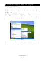
2.2.1. Program start with modules Power Express ® online
Link the Power Express® system through the module PEC25 into the serial port of your computer. All
Power Express® modules must have power supply. Run the PEX program from the Windows Start
menu.
Fig. 1
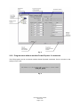
Once you have loaded the program, the main program window will be displayed. There is a list of the
connected modules with their serial numbers on the left side of the main window, and a space for their
parameters on the right side of the window.
User Manual PEX Software
www.cue.cz
Page 5 of 25
Fig. 2
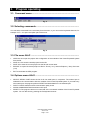
2.2.2. Program start without modules Power Express ® connected
The PEX program can be run without modules Power Express® connected. There is a notice on the
startup in such case:
Fig. 3
User Manual PEX Software
www.cue.cz
Page 6 of 25
3.
Program operating
3.1. Command menu................................................................................
Fig. 4
3.2. Selecting commands .........................................................................
You can select commands in the usual way from the menu, or you can use the keyboard shortcuts, for
example: ALT + O to open the Option part of the menu.
Fig. 5
3.3. File menu Alt+F ..................................................................................
•
•
•
•
•
OPEN Ctr+O to open the project with configuration of the modules of the Power Express® system
from the file.
SAVE Ctr+S to save the actual project into the file.
SAVE AS to save the current project into the file with a new name.
EXPORT to export the actual project as file for: Excel (*.csv), Internet Explorer (*.htm), Plain text
(*.txt)
EXIT to terminate the PEX program.
3.4. Options menu Alt+O ..........................................................................
•
•
•
•
SELECT SERIAL PORT shows the list of all free serial ports in computers. The marked port is
selected for the communication with the modules of the Power Express® system. If you select any
other serial port, the program performs RESET and loads data from new selected port.
PARITY CHECK switches on/off communication parity check
QUICK COMMUNICATIONS switches on/off quick
RESET F5 The program carries out a new load of the connected modules of the Power Express®
system. You can also do it by pressing the F5 keyboard shortcut.
User Manual PEX Software
www.cue.cz
Page 7 of 25
3.5. Tools menu Alt+T...............................................................................
LOCATE F3 By this command you can seek a channel without knowing its address by pressing its
button on the module.
Fig. 6
You can STOP this function by pressing the STOP button. If there is more than one channel with the
same address, the LOCATE command does not run and a warning message is shown:
Fig. 7
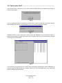
ADRESS CHECK F4 This command is used to check the addresses of all connected modules. A
special window opens to display the results of this command. There is a list of all connected channels
on the right side of the window.
Fig. 8
In the left part of the screen there is a chart clearly showing the positioning of channel addresses of
the given type. By selecting the type of output in the list (A or D in the Bank column) you choose the
chart for analog or digital channels.
User Manual PEX Software
www.cue.cz
Page 8 of 25
Fig. 9
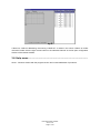
If there is a conflict in addressing, the warning “CONFLICT“ is shown in the column “Status“ at conflict
channels. Double click the right mouse button on the selected channels in the list open configuration
window of the relevant module.
3.6. Help menu ..........................................................................................
About... Shows a window with the program version and contact addresses of producers.
User Manual PEX Software
www.cue.cz
Page 9 of 25
4.
Configuration of the Power Express® modules
Double click the module list in the main window to show editable parameters of the module. You can
change parameters by:
type writing,
selecting from a list of options,
increasing or decreasing numerical values, or
dragging scroll bars.
If the value of any parameter is changed, its background flashes red to indicate change. If you move
the mouse cursor to ten given parameter, its previous value is shown. Before the transmission of new
parameters, the original values from the module can be recovered by pressing UPLOAD (or Alt+U).
Pressing DOWNLOAD (or Alt+D) transfers the current parameters into the configured module.
User Manual PEX Software
www.cue.cz
Page 10 of 25
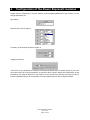
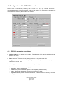
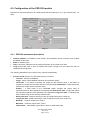
4.1. Configuration of the PER 610 module
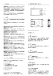
PER610 is a six-channel relay switching unit for loads up to 10 A per channel. There are all
changeable parameters in the configuration window of the module. The parameters in the upper part
of the window are shared by all channels of the module.
Fig. 10
4.1.1. PER 610 parameters description
•
•
•
•
Interface address 0-15 address of the module. The addresses of all channels of this module are
based on this value.
Bank 0-9 module group
Filter 0-180 msec. minimum time of pressing the button for the press to be valid.
Long press 0-900 msec. If the time of pressing the button is longer than this value, the press is
interpreted as a long press.
The following parameters can be set for each channel independently:
•
Function mode selection for control relay by its buttons
− no action - buttons are disabled.
− coded - Each press causes the negation of the relay state (switched on/off)
− relay - When button is pressed, the output is on, otherwise it is off.
− system on - When pressed, the relay switches on; it can be switched off only by a command
through serial line.
User Manual PEX Software
www.cue.cz
Page 11 of 25
−
−
−
−
−
−
run – a short press switches the relay on for the period of time entered in its parameter. Long
time press do the relay on only for button is holding. It is useful in couple with other channel
with direction mode for controlling of AC motors.
direction - it is useful for selecting direction of controlled AC motors. After 200 ms the couple
relay with mode run is switched on too.
delayed off - the relay is switched on at once, but it is switched off after delay time.
delayed on - the relay is switched off at once but it is switched on after delay time.
run DC (firmware 1.09 or higher) - short press switch relay on for parameter time. Long time
press do the relay on only for button is holding. It is useful in couple with other channel with
same mode for controlling DC motors.
pulse (firmware 1.10 or later) – the relay is switched on for a short time impulse entered in the
parameter.
•
Time parameter in seconds for modes working with time. There are the following time formats
available for units with firmware 1.11 or higher:
− seconds 0,1 – 999,9 s
− minutes - seconds: 00:01 – 59:59
− hours - minutes: 00:01 – 12:59 (longest avilable time is 12 hours 59 minutes)
•
•
Label - Channel legend which can consist of up to 22 characters.
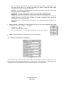
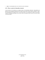
4.1.2. Direct control of the channels
Fig. 11
If you check off the On-line box, the current state of the on- and off- outputs is shown next to the
channel names, being constantly updated. An output that is off is indicated by an activated button.
Clicking the button of the desired channel causes the negation of the output state.
User Manual PEX Software
www.cue.cz
Page 12 of 25
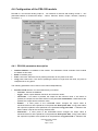
4.2. Configuration of one channel dimming modules PED 108, PET
102 and PET 105
PED108 is a one-channel dimmer for resistive and inductive loads up to 8 A. PET102 is a one-channel
dimmer for resistive and capacitive loads up to 2 A suitable for dimmable electronic transformers.
PET105 is a one-channel dimmer for resistive and capacitive loads up to 5 A suitable for dimmable
electronic transformers.
Fig. 12
4.2.1. PED 108, PET 102, PET 105 parameters description
•
•
•
•
Interface address 0-31 address of the module. The addresses of both channels of this module
are based on this value.
Bank 0-9 module group
Filter 0-180 msec. minimum time of pressing the button for the press to be valid.
Long press 0-900 msec. If time of pressing the button is longer than this value, the press is
interpreted as a long press.
The following parameters can be set for each channel independently:
•
Function mode selection for control dimmer by it’s buttons
− no action - buttons are disabled.
− toggle - switch outputs between maximum and minimum values.
− solid state - if no button is pressed, the output value has the minimum value. If one button is
pressed, the output has the value entered in the parameter Intermediate. If both buttons are
pressed, the output has the maximum value.
− dimmer – a short press of the UP/DOWN button changes the output value to
maximum/minimum at the speed set in the parameter Short press fade. A long press makes
the output dim up/down at the speed set in the parameter Long press fade. A release of the
button makes it stop at the currently reached value.
− Short press fade - speed of dimming in case of normal button press, 0-99.9 sec.
− Long press fade - speed of dimming in case of long time button press, 0-99.9 sec.
− Minimum - minimum output value, 0-99 %.
− Maximum - maximum output value, 0-99 %.
− Intermediate - intermediate output value, 0-99 % for solid state mode.
User Manual PEX Software
www.cue.cz
Page 13 of 25
•
Label - Channel legend which can consist of up to 22 characters.
4.2.2. Direct control of dimmable channels
If the On-line box is checked, any changes made to the parameters Minimum, Intermediate and
Maximum are immediately transferred to the output of the module, which makes it possible to control
the real brightness of the light source. If the On-line switch is not activated, the output of the module
remains unchanged during setting. The current value of the output is shown next to the On-line, being
constantly updated.
User Manual PEX Software
www.cue.cz
Page 14 of 25
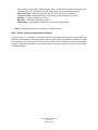
4.3. Configuration of the PED 202 module
PED202 is a two-channel dimmer for resistive and inductive loads up to 2.7 A per channel (max. 4 A
total).
Fig. 13
4.3.1. PED 202 parameters description
•
•
•
•
Interface address 0-15 address of the module. The addresses of both channels of this module
are based on this value.
Bank 0-9 module group
Filter 0-180 msec. Minimum time of pressing the button for the press to be valid.
Long press 0-900 msec. If time of pressing the button is longer than this value, the press is
interpreted as a long press.
The following parameters can be set for every channel independently:
•
Function mode selection for control dimmers by it’s buttons
− no action - buttons are disabled.
− toggle - switch outputs between maximum and minimum values.
− solid state - if no button is pressed, the output has the minimum value. If one button is
pressed, the output has the value entered in the parameter Intermediate. If both buttons are
pressed, the output has the maximum value.
− dimmer – a short press of the UP/DOWN button changes the output value to
maximum/minimum at the speed set in the parameter Short press fade. A long press makes
the output dim up/down at the speed set in the parameter Long press fade. A release of the
button makes it stop at the currently reached value.
− Short press fade - speed of dimming in case of normal button press, 0-99.9 sec.
− Long press fade - speed of dimming in case of long time button press, 0-99.9 sec.
− Minimum - minimum output value, 0-99 %.
− Maximum - maximum output value, 0-99 %.
− Intermediate - intermediate output value, 0-99 % for solid state mode.
User Manual PEX Software
www.cue.cz
Page 15 of 25
•
Label - Channel legend which can consist of up to 22 characters.
4.3.2. Direct control of dimmable channels
If the On-line box is checked, any changes made to the parameters Minimum, Intermediate and
Maximum are immediately transferred to the output of the module, which makes it possible to control
the real brightness of the light source. If the On-line switch is not activated, the output of the module
remains unchanged during setting. The current value of the output is shown next to the On-line, being
constantly updated.
User Manual PEX Software
www.cue.cz
Page 16 of 25
4.4. Configuration of the PEA 208 module
PEA208 is a two-channel analog output 0 - 10V interface for devices with analog control 0 - 10V
(dimmable ballast for fluorescent lamps – Osram, Siemens, Helvar, Philips, dimmers, frequency
converters ...).
Fig. 14
4.4.1. PEA 208 parameters description
•
•
•
•
Interface address 0-15 address of the module. The addresses of both channels of this module
are based on this value.
Bank 0-9 module group
Filter 0-180 msec. Minimum time of pressing the button for the press to be valid.
Long press 0-900 msec. If the time of pressing the button is longer than this value, the press is
interpreted as a long press.
The following parameters can be set for each channel independently:
•
Function mode selection for control dimmers by it’s buttons
− no action - buttons are disabled.
− toggle - switch outputs between maximum and minimum values.
− solid state - if no button is pressed, the output has the minimum value. If one button is
pressed, the output has the value entered in the parameter Intermediate. If both buttons are
pressed, the output has the maximum value.
− dimmer – a short press of the UP/DOWN button changes the output value to
maximum/minimum at the speed set in the parameter Short press fade. A long press makes
the output dim up/down at the speed set in the parameter Long press fade. A release of the
button makes it stop at the currently reached value.
− fluorescent – a short press of the UP/DOWN button changes the output value to
maximum/minimum at the speed set in the parameter Short press fade. A long press makes
the output dim up/down at the speed set in the parameter Long press fade. A release of the
User Manual PEX Software
www.cue.cz
Page 17 of 25
−
−
−
−
−
•
button makes it stop at the currently reached value. If button down is held, the value does not
go all the way to 0%, but stops at 5 %. For a total switch-off use repeated quick press.
Short press fade - speed of dimming in case of normal button press, 0-99.9 sec.
Long press fade - speed of dimming in case of long time button press, 0-99.9 sec.
Minimum - minimum output value, 0-99 %.
Maximum - maximum output value, 0-99 %.
Intermediate - intermediate output value, 0-99 % for solid state mode.
Label - Channel legend which can consist of up to 22 characters.
4.4.2. Direct control of dimmable channels
If the On-line box is checked, any changes made to the parameters Minimum, Intermediate and
Maximum are immediately transferred to the output of the module, which makes it possible to control
the real brightness of the light source. If the On-line switch is not activated, the output of the module
remains unchanged during setting. The current value of the output is shown next to the On-line, being
constantly updated.
User Manual PEX Software
www.cue.cz
Page 18 of 25
4.5. Configuration of the PEF 200 module
PEF200 is a two-channel interface for fluorescent lamp dimming ballasts with DSI control signal
(TRIDONIC, ZUMTOBEL).
Fig. 15
4.5.1. PEF 200 parameters description
•
•
•
•
Interface address 0-15 address of the module. The addresses of both channels of this module
are based on this value.
Bank 0-9 module group
Filter 0-180 msec. Minimum time of pressing the button for the press to be valid.
Long press 0-900 msec. If the time of pressing the button is longer than this value, the press is
interpreted as a long press.
The following parameters can be set for each channel independently:
•
Function mode selection for control dimmers by it’s buttons
− no action - buttons are disabled.
− toggle - switch outputs between maximum and minimum values.
− solid state - if no button is pressed, the output has the minimum value. If one button is
pressed, the output has the value entered in the parameter Intermediate. If both buttons are
pressed, the output has the maximum value.
− dimmer – a short press of the UP/DOWN button changes the output value to
maximum/minimum at the speed set in the parameter Short press fade. A long press makes
the output dim up/down at the speed set in the parameter Long press fade. A release of the
button makes it stop at the currently reached value. If button down is held, the value does not
go all the way to 0%, but stops at 1 %. For a total switch-off use repeated quick press.
− Short press fade - speed of dimming in case of normal button press, 0-99.9 sec.
− Long press fade - speed of dimming in case of long time button press, 0-99.9 sec.
− Minimum - minimum output value, 0-99 %.
− Maximum - maximum output value, 0-99 %.
− Intermediate - intermediate output value, 0-99 % for solid state mode.
User Manual PEX Software
www.cue.cz
Page 19 of 25
•
Label - Channel legend which can consist of up to 22 characters.
4.5.2. Direct control of dimmable channels
If the On-line box is checked, any changes made to the parameters Minimum, Intermediate and
Maximum are immediately transferred to the output of the module, which makes it possible to control
the real brightness of the light source. If the On-line switch is not activated, the output of the module
remains unchanged during setting. The current value of the output is shown next to the On-line, being
constantly updated.
User Manual PEX Software
www.cue.cz
Page 20 of 25
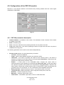
4.6. Configuration of the PEF 150 module
PEF150 is interface for control up to 64 dimmable ballasts for fluorescent lamps on one bus divided up
to 15 independent groups.
Fig. 16
4.6.1. PEF 150 parameters description
•
•
•
•
Interface address address of the module. The addresses of both channels of this module are
based on this value.
Bank 0-9 module group
Filter 0-180 msec. Minimum time of pressing the button for the press to be valid.
Long press 0-900 msec. If the time of pressing the button is longer than this value, the press is
interpreted as a long press.
The followingparameters can be set for the first and second channel independently. These channels
can be controlled by buttons. The number of channels equals the number of controlled DALI groups.
•
Function mode selection for control dimmers by its buttons
− no action - buttons are disabled.
− toggle - switch outputs between maximum and minimum values.
− solid state - if no button is pressed, the output has the minimum value. If one button is
pressed, the output has the value entered in the parameter Intermediate. If both buttons are
pressed, the output has the maximum value.
− dimmer – a short press of the UP/DOWN button changes the output value to
maximum/minimum at the speed set in the parameter Short press fade. A long press makes
the output dim up/down at the speed set in the parameter Long press fade. A release of the
User Manual PEX Software
www.cue.cz
Page 21 of 25
−
−
−
−
−
•
button makes it stop at the currently reached value. If button down is held, the value does not
go all the way to 0%, but stops at 1 %. For a total switch-off use repeated quick press.
Short press fade - speed of dimming in case of normal button press, 0-99.9 sec.
Long press fade - speed of dimming in case of long time button press, 0-99.9 sec.
Minimum - minimum output value, 0-99 %.
Maximum - maximum output value, 0-99 %.
Intermediate - intermediate output value, 0-99 % for solid state mode.
Label - Channel legend which can consist of up to 22 characters.
4.6.2. Direct control of dimmable channels
If the On-line box is checked, any changes made to the parameters Minimum, Intermediate and
Maximum are immediately transferred to the output of the module, which makes it possible to control
the real brightness of the light source. If the On-line switch is not activated, the output of the module
remains unchanged during setting. The current value of the output is shown next to the On-line, being
constantly updated.
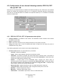
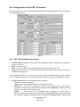
4.6.3. DALI ballasts configuration by PEF 150 module
After connecting PEF150 to the DALI bus, which is connected to max. 63 ballasts, it is necessary to
set the addresses in DALI ballasts and assign them into groups. These can be controlled from the PEF
150 control module. You can start this configuration by pressing the Configure DALI button. That
starts an initialization and a test of the ballast’s addresses.
If the addresses of ballasts do not come in a continuous sequence (configuration has not yet been
carried out), the following message is shown:
Fig. 17
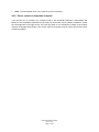
If you select Yes, the control of addresses runs again. Otherwise the program asks you when you
want to start setting addresses.
User Manual PEX Software
www.cue.cz
Page 22 of 25
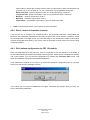
Fig. 18
Once you have confirmed by pressing Yes, ally adresses of ballasts are deleted (information about
groups remain saved) and a new assigning of addresses for a given set of ballasts is carried out.
Once everyvery founded ballast has its short address, a form for assigning ballasts into channels
(groups) is shown.
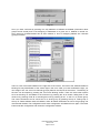
Fig. 19
There is a list of all found ballasts on the right side of the screen. The tube of the sellected ballast is
blinking for easy identification of the chosen light in the room. After you have locallised the light, you
can assign it into one ore more channels (groups) listed in the left part of the screen.. The blinking of
the tube can be stoped by pressing the “Fluor tube blinking” button. There are some other options
such as switching on all ballasts to the maximum by pressing the All on button, fading them to the
minimum by pressing Fade all or switching them off by pressing All off. to the m in a chosen group.
The same commands can be carried out for a whole group by pressing Group on, Fade group or
Group off. Reset ballasts resets all ballasts, while all ballast addresses as well as all grouping into
channels ale deleted. The Configurate button starts configuration of ballasts all over again. The Close
button ends the configuration and closes the configuration window.
User Manual PEX Software
www.cue.cz
Page 23 of 25
5.
Software and Firmware License
END-USER NOTICE AND LICENSE AGREEMENT FROM CUE, a.s.
NOTICE TO END-USER: CAREFULLY READ THE FOLLOWING LEGAL AGREEMENT (THIS "LICENSE").
INSTALLATION OR USE OF THE ENCLOSED CUE, a.s. SOFTWARE PROGRAMS (COLLECTIVELY,
"SOFTWARE") ON YOUR COMPUTER SYSTEMS OR HARDWARE DEVICES CONSTITUTES YOUR
ACCEPTANCE OF THESE TERMS. IF YOU DO NOT AGREE TO THE TERMS OF THIS LICENSE, PROMPTLY
DELETE THE SOFTWARE FROM YOUR COMPUTER SYSTEMS AND HARDWARE DEVICES, DESTROY
ANY COPIES YOU MADE OF THE SOFTWARE OR ANY INSTALLATION MEDIA OF THE SOFTWARE
INCLUDED WITH YOUR SYSTEM, AND DISPOSE OF ALL WRITTEN MATERIALS IN YOUR POSSESSION
REGARDING THE SOFTWARE.
License Grant: CUE grants to You, as an individual, a license to install and use one (1) copy of the Software on
a single computer at a time; provided, however, that You may make copies of the Software solely for Your
development of applications for CUE hardware and demonstration versions of such applications. Any applications
created with the Software may only be used with Cue hardware. Your license to use the Software is conditioned
upon Your compliance with the terms of this License. A License is required for each end-user of the Software. A
license is required for each installation of the Software. You may make one (1) copy of the Software for archival
purposes only. You may use this Software only in connection with CUE hardware. You must have acquired the
Software directly in connection with the purchase of CUE hardware from CUE or from a CUE approved reseller
for this license to be effective. If You have purchased a Site License, You may complete only the number of
installations specified in the License Agreement accompanying the Software.
Copyright: The Software and software built into CUE hardware ("Firmware") are protected by copyright law and
international treaty provisions. You acknowledge that no title to the intellectual property in the Software and
Firmware is transferred to You. You further acknowledge that title and full ownership rights to the Software and
Firmware will remain the exclusive property of CUE, and You will not acquire any rights to the Software and
Firmware except as expressly set forth in this License. You agree that any copies of the Software will contain the
same proprietary notices which appear on and in the Software.
Prohibited Uses: Without obtaining prior written permission from CUE, You may not (a.) use, copy, modify, alter,
or transfer the Software or documentation except as expressly provided in this License; (b.) translate,
disassemble, decompile, reverse program or otherwise reverse engineer the Software and Firmware; (c.)
sublicense or lease the Software or its documentation (d.) use this Software with any hardware other than
products produced by CUE or in connection with applications being developed for CUE hardware; or (e.) use the
Software in a multi-user, network, or multiple computer environment or in a rental, time sharing or computer
service business. Without prejudice to any other rights, CUE may terminate this License if You fail to comply with
its terms and conditions. In such event, You must immediately destroy all copies of the Software.
No Other Warranties: CUE DOES NOT WARRANT THAT THE SOFTWARE AND FIRMWARE IS ERROR
FREE. CUE DISCLAIMS ALL WARRANTIES WITH RESPECT TO THE SOFTWARE AND FIRMWARE, EITHER
EXPRESS OR IMPLIED, INCLUDING BUT NOT LIMITED TO IMPLIED WARRANTIES OF MERCHANTABILITY,
FITNESS FOR A PARTICULAR PURPOSE AND NONINFRINGEMENT OF THIRD PARTY RIGHTS. SOME
JURISDICTIONS DO NOT ALLOW THE EXCLUSION OF IMPLIED WARRANTIES OR LIMITATIONS OF HOW
LONG AN IMPLIED WARRANTY MAY LAST, OR THE EXCLUSION OF LIMITATION OF INCIDENTAL
DAMAGES, SO THE ABOVE LIMITATIONS OR EXCLUSIONS MAY NOT APPLY TO YOU. THIS WARRANTY
GIVES YOU SPECIFIC LEGAL RIGHTS AND YOU MAY ALSO HAVE OTHER RIGHTS WHICH VARY FROM
JURISDICTION TO JURISDICTION.
No Liability for Consequential Damages: IN NO EVENT SHALL CUE BE LIABLE TO YOU FOR ANY
CONSEQUENTIAL, SPECIAL, INCIDENTAL, OR INDIRECT DAMAGES OF ANY KIND ARISING OUT OF THE
PERFORMANCE OR USE OF THE SOFTWARE, EVEN IF CUE HAS BEEN ADVISED OF THE POSSIBILITY
OF SUCH DAMAGES.
Label on Hardware: Use of this hardware and the software programs controlling this hardware is subject to the
terms of the Software and Hardware License Agreements (the “License Agreements”). You should not use the
software and hardware until you have read the License Agreements. By using the software and hardware, you
signify that you have read the Licenses Agreements and accept their terms. The “License Agreement” is available
at www.cuesystem.com.
Trademark Notice: CUE and the CUE logo are trademarks of CUE, a.s. in the United States and in other
countries.
User Manual PEX Software
www.cue.cz
Page 24 of 25
Notes
User Manual PEX Software
www.cue.cz
Page 25 of 25