1
USER MANUAL
TILTIX MEMS INCLI NO METER W ITH CANOPEN IN TERFACE
AMERICAS
FRABA Inc.
1800 East State Street, Suite 148
Hamilton, NJ 08609-2020, USA
T +1 609 750-8705, F +1 609 750-8703
www.posital.com, [email protected]
EUROPE
FRABA AG
Carlswerkstrasse 13c
51063 Cologne, GERMANY
T +49 221 96213-0, F +49 221 96213-20
www.posital.com, [email protected]
ASIA
FRABA Pte. Ltd.
20 Kallang Avenue
Singapore 339411, SINGAPORE
T +65 6514 8880, F +65 6271 1792
www.posital.com, [email protected]
USER MANUAL
TILTIX MEMS INCLI NO METER W ITH CANOPEN IN TERFACE
1
Inhaltsverzeichnis
1
2
Inhaltsverzeichnis ......................................... 2
General Safety Advice.................................. 4
2.1
Important Information ........................... 4
3
About this Manual ........................................ 5
3.1
Background .......................................... 5
7.9
Object 1801h: 2nd Transmit PDO
Communication Parameter ................. 18
7.10
Transmission Mode ............................ 19
7.11
Inhibit Time ......................................... 19
7.12
Event Timer ........................................ 19
7.13
Cyclic Timer........................................ 19
7.14
Object 1A00h: 1st Transmit PDO
Mapping Parameter ............................ 20
Version Management ........................... 5
3.3
Imprint .................................................. 5
3.4
Copyright.............................................. 5
3.5
User Annotation ................................... 5
3.6
Document History ................................ 5
Introduction .................................................. 6
TILTIX .. Error! Bookmark not defined.
7.15
4.1
Object 1A01h: 2nd Transmit PDO
Mapping Parameter ............................ 20
4.2
CANopen Interface .............................. 6
7.16
Types of SDO ..................................... 20
4.3
TILTIX CANopen .................................. 6
8
8.1
Working with Schneider PLC ...................... 22
Types of SDO ..................................... 22
4.4
Typical Applications of TILTIX.............. 7
TILTIX – Modes and Parameter ................... 8
Pre-Operational Mode .......................... 9
8.2
Types of SDO ..................................... 22
5.1
8.4
Software Project Information .............. 23
5.2
Operational Mode ................................ 9
8.5
Controller Description ......................... 23
5.3
Stopped Mode .................................... 10
8.6
CANopen Master Configuration ......... 23
5.4
Re-Initialization of the Inclinometer .... 10
8.7
Connection Network Setup ................. 24
5.5
Boot-up Procedur ............................... 11
9.1
Configuration .............................................. 25
TILTIX Process Data Objects (PDO)
Mapping ............................................. 25
9.2
TILTIX CANopen Node Configuration 25
9.3
CANopen bus network configuratio .... 25
9.4
Linking of CANOpen Master and TILTIX
Transmit-PDOs................................... 26
9.5
TILTIX & Controller Memory
Configuration ...................................... 26
9.6
Debugging .......................................... 26
9.7
Run..................................................... 28
9.8
Resetting CANOpen Communication . 28
9.9
Resetting CANOpen Nodes ............... 28
9.10
Position Readout ................................ 29
9.11
Readout Using Animation Table ......... 29
5
5.6
7
Object 1800h: 1st Transmit PDO
Communication Parameter ................. 18
3.2
4
6
7.8
Usage of Layer Settings Service (LSS)
11
Installation .................................................. 12
6.1
Accessories........................................ 12
6.2
Pin Assignement ................................ 12
6.3
Installation Precautions ...................... 12
6.4
Mounting Instructions ......................... 13
6.5
Bus Termination ................................. 13
6.6
Measurement Axes ............................ 14
TILTIX Software Configuration ................... 15
7.1
Default Factory Settings ..................... 15
7.2
Active Programming Objects .............. 15
7.3
Programmable Parameters ................ 16
7.4
Command Description........................ 16
7.5
Data Length of Commands ................ 16
7.6
Frequently Used Commands ............. 17
7.7
PDO Transmission ............................. 18
9
10
Frequently Asked Question ................... 31
............................................................................ 35
11
Appendix A: TILTIX CANopen Objects . 36
11.1
Object 1000h: Device Type ................ 36
11.2
AMERICAS
FRABA Inc.
1800 East State Street, Suite 148
Hamilton, NJ 08609-2020, USA
T +1 609 750-8705, F +1 609 750-8703
www.posital.com, [email protected]
Object 1001h: Error Register .............. 36
EUROPE
FRABA AG
Carlswerkstrasse 13c
51063 Cologne, GERMANY
T +49 221 96213-0, F +49 221 96213-20
www.posital.com, [email protected]
ASIA
FRABA Pte. Ltd.
20 Kallang Avenue
Singapore 339411, SINGAPORE
T +65 6514 8880, F +65 6271 1792
www.posital.com, [email protected]
USER MANUAL
TILTIX MEMS INCLI NO METER W ITH CANOPEN IN TERFACE
11.3
Object 1003h: Pre-Defined Error Field36
11.34
Object 6023h: Slope Lateral16 Offset 49
11.4
Object 1005h: COB-ID Sync .............. 37
11.35
11.5
Object 1008h: Mfr Device Name ........ 37
Object 6024h: Differential Slope
Lateral16 Offset .................................. 49
11.6
Object 1009h: Mfr Hardware Version . 37
11.36
Object 6114h: Differential Slope Long32
Offset (TILTIX360).............................. 50
11.7
Object 100Ah: Mfr Software Version .. 37
11.8
Object 100Ch: Guard Time ................ 37
12
12.1
Appendix B: Ordering Code .................. 54
TILTIX – Industrial .............................. 54
11.9
Object 100Dh: Life Time Factor ......... 38
12.2
TILTIX – Heavy-Duty .......................... 54
11.10
Object 1010h: Store Parameters ........ 38
11.11
Object 1011h: Restore Parameters .... 39
13
13.1
Appendix C: Output Graphs .................. 55
TILTIX 360: CANopen Output Values 55
11.12
Object 1014h: COB-ID Emergency .... 39
13.2
TILTIX 080 : CANopen Output Values 55
11.13
Object 1016h: Consumer Heartbeat
Time ................................................... 40
11.14
Object 1017h: Producer Heartbeat Time
40
11.15
Object 1018: Identity Object ............... 40
11.16
Object 2200h: Cyclic Timer ................ 41
11.17
Object 2300h: Save Parameter with
Reset.................................................. 41
11.18
Object 2600h: Preset X-Axis (80º
Version) / Preset (360º Version)......... 41
11.19
Object 2601h: Preset Y-Axis (80º
Version).............................................. 42
11.20
Object 3000h: Node Number ............. 42
11.21
Object 3001h: Baud rate .................... 43
11.22
Object 3002h: Termination Resistor ... 43
11.23
Object 3022h: Digital Recursive Filter 44
11.24
Object 3100h: Moving Average Filter . 44
11.25
Object 6000h: Resolution ................... 44
11.26
Object 6010h: Slope Long16.............. 45
11.27
Object 6011h: Slope Long16 Operating
Parameter .......................................... 45
11.28
Object 6012h: Slope Long16 Preset
Value .................................................. 46
11.29
Object 6013h: Slope Long16 Offset ... 46
11.30
Object 6014h: Differential Slope Long16
Offset ................................................. 47
11.31
Object 6020h: Slope Lateral16 ........... 47
11.32
Object 6021h: Slope Lateral16
Operating Parameter.......................... 48
11.33
Object 6022h: Slope Lateral16 Preset
Value .................................................. 49
14
Glossary ................................................ 57
15
Check Out Some of the Other POSITAL
Products 59
16
Disclaimer ............................................. 60
USER MANUAL
TILTIX MEMS INCLI NO METER W ITH CANOPEN IN TERFACE
2
General Safety Advice
2.1
Important Information
The addition of this symbol to a
Read these instructions carefully, and have a look
Danger or Warning safety label
at the equipment to become familiar with the
indicates that an electrical hazard
device before trying to install, operate, or maintain
exists, which will result in personal
it.
injury if the instructions are not
followed.
The following special messages may appear
throughout this documentation or on the equipment
This is the safety alert symbol. It is
to warn of potential hazards or to call attention
used to alert you to potential
towards
personal injury hazards. Obey all
information
that
clarifies/simplifies
a
procedure.
safety messages that follow this
symbol to avoid possible injury or
Please Note: Electrical equipment should be
serviced
only
by
qualified
personnel.
death.
No
responsibility is assumed by POSITAL for any
consequences arising out of the use of this
material. This document is not intended as an
instruction manual for untrained personnel.
Page 4
ACS CANopen User Manual
Version: 20111031
USER MANUAL
TILTIX MEMS INCLI NO METER W ITH CANOPEN IN TERFACE
3
About this Manual
3.1
Background
This user manual explains how to install and
interface
configure the TILTIX inclinometer with a CANopen
®
TWIDO PLC.
3.2
3.3
Version Management
with
illustrations from
a
Schneider
Imprint
-
Updated On: 201110031
FRABA NV
-
Document Name:
Jan Campertstraat 5,
Manual_TILTIX_CANopen_General.pdf
NL-6416 SG Heerlen
T +49 221-96213-0
[email protected], www.fraba.com
3.4
Copyright
CANopen® and CiA® are registered community
to
trademarks of CAN in Automation e.V.
approval by FRABA N.V. Nor is any liability
copy
this
documentation
without
written
assumed for damages resulting from the use of the
© FRABA N.V., all rights reserved – Claims
information
copyright on this documentation. It is not allowed
publication and features described herein are
to modify, extend, or hand over to a third party and
subject to change without notice.
3.5
contained
herein.
Further,
this
User Annotation
All readers are highly welcome to send us
e-mail at the following e-mail addresses. For
feedback and comments about this document.
America [email protected], for Asia [email protected],
Depending on your region you can reach us by
for Europe [email protected].
3.6
Document History
Document
Manual_TILTIX_CANopen_General.pdf
Created
2011/10/31
Author
ANA
Reviewers
MMO / DPR
Versions
First Release – 20111031
Page 5
ACS CANopen User Manual
Version: 20111031
USER MANUAL
TILTIX MEMS INCLI NO METER W ITH CANOPEN IN TERFACE
4
Introduction
This manual explains how to install and configure
and heavy duty applications. The TILTIX CANopen
the TILTIX gravity referenced inclinometers with a
is based on the DS410 standard.
CANopen interface, suitable for industrial, military
4.1
TILTIX Inclinomter
ACCELENS inclinometers sense and measure the
The TILTIX series of inclinometers, both industrial
angle of tilt (inclination/slope/elevation) of an object
and heavy-duty lines, are available in two variants.
with respect to the force of gravity.
First, a single axis measurement variant with a
range of 360° and the other variant, a dual axis
The basic principle behind this TILTIX inclinometer
measurement capable TILTIX model with a range
is a Micro-Electro-Mechanical Systems (MEMS)
of ±80°.
sensor cell that is embedded to a fully molded
ASIC. The angle is measured with the relative
change in electrical capacitance in the MEMS cell.
4.2
CANopen Interface
CANopen is based on the Controller Area Network
In simple terms, CANopen works as a client-server
(CAN)
automotive
model. Each device checks whether the bus is
industries in the 80s. The application protocol
free, and if it is free the device can send
CANopen was introduced by the multi vendor
messages. If two devices try to access the bus at
association CAN in Automation (CiA) to ensure a
the same time, the device with the higher priority
full compatibility of industrial automation products.
level has permission to send its message first.
It is a multiple access system (maximum: 127
Devices with the lowest priority level must cancel
devices), which means that all devices can access
their data transfer and wait before re-trying to send
the bus. These devices are the components of the
their message.
that
was
developed
by
CANopen bus.
4.3
TILTIX CANopen
The TILTIX CANopen inclinometer corresponds to
capable TILTIX model with a range of ±80°. In
the
CANopen
addition to high resolution, accuracy and protection
standards. It is available in industrial and heavy-
class of IP69K, it has built-in active linearization
duty
and
inclinometer
housings,
profile
and
two
DS
410
measurement
axes
variants. The single axis measurement variant with
temperature
compensation.
This
makes
TILTIX suitable for rugged environments and
a range of 360° and a dual axis measurement
Page 6
ACS CANopen User Manual
Version: 20111031
USER MANUAL
TILTIX MEMS INCLI NO METER W ITH CANOPEN IN TERFACE
versatile applications in industrial, heavy duty and
is received. The position value is sent
military applications.
every n SYNCs (n ≥ 1).
-
State change mode: The position value is
The inclinometer supports the following operating
transmitted whenever the position of the
modes:
inclinometerchanges (minimum time
-
interval settable).
Polled mode: The position value is
transmitted only on request.
-
-
Cyclic mode: The position value is sent
Various software tools for configuration and
cyclically (regular, adjustable intervals) on
parameter-setting are available from different
the bus.
suppliers. It is easy to align and program the
SYNC mode: The position value is sent
inclinometers using the EDS (electronic data
after a synchronization message (SYNC)
sheet) configuration file provided. (Refer to section
3.1)
4.4
Typical Applications of TILTIX
-
Cranes and Construction Machinery
-
Automated Guided Vehivles (AGV)
-
Medical Systems
-
Automatic Assembling Machinery
-
Elevated Platforms
-
Boring and Drilling Applications
-
Mobile Lifts and Fire Engines
-
Levelling and Flattening
Page 7
ACS CANopen User Manual
Version: 20111031
USER MANUAL
TILTIX MEMS INCLI NO METER W ITH CANOPEN IN TERFACE
5
TILTIX – Modes and Parameter
The purpose of this chapter is to describe the
going
available configuration parameters of the TILTIX
describes useful technical terms and acronyms for
inclinometers with CANopen interface. Before
CANopen network communication.
Node-ID
into
details
the
following
information
In the CAN network each device has a Node-ID that is used to
address the device in the network and to define it’s priority of
EDS (Electronic Data Sheet)
An EDS file describes the communication properties of a device
on the CAN network (baud rates, transmission types, I/O features,
etc.). It is provided by the device manufacturer and is used in the
configuration tool to configure a node (like a driver in an operating
system).
PDO (Process Data Object)
CANopen frame containing I/O data. We distinguish between:
Transmit-PDO (TPDO): data provided by a node
Receive-PDO (RPDO): data to be consumed by a node
The transmission direction is always seen from a node's point of
view.
SDO (Service Data Object)
SDOs are typically used to read or write parameters while the
application is running.
COB-ID (Communication Object
Each CANopen frame starts with a COB-ID working as the
Identifier)
Identifier. During the configuration phase, each node receives the
COB-ID(s) for which it is the provider (or consumer).
NMT (Network Management
The NMT protocols are used to issue state machine change
Transition)
commands (i.e. to start and stop the devices), detect remote
device boot ups and error conditions.
Page 8
ACS CANopen User Manual
Version: 20111031
USER MANUAL
TILTIX MEMS INCLI NO METER W ITH CANOPEN IN TERFACE
5.1
Pre-Operational Mode
If the device is in this state, its configuration can be
If configuration is complete, the device goes into
modified. However, only SDOs can be used to
one of the following states on receiving the
read or write device-related data. The device goes
corresponding indication:
into Pre-Operational Mode:
-
-
After the power up
-
On receiving the Enter Pre-Operational
"Stopped" on receiving the
"Stop Remote Node" NMT indication
-
"Operational" on receiving the
NMT indication, if it was in Operational
"Start Remote Node" NMT indication
Mode before
To set a node to pre-operational mode, the master
must send the following message:
Identifier
Byte 0
Byte 1
Description
0h
80 h
00
NMT-PreOp, All Nodes
0h
80 h
NN
NMT-PreOp, NN
NN: Node Number
5.2
Operational Mode
The device goes into the "Operational" state if it
Note:
was in the "Pre-Operational" state on receiving the
"Operational"
"Start Remote Node" indication. If the CANopen
consequences and should therefore only be made
network is started using the "Node Start" NMT
in "Pre-Operational" mode.
services
in
"Operational"
state,
all
Modifications
mode
to
the
may
configuration
have
in
unexpected
device
functionalities can be used. Communication can
To put one or all nodes in “Operational” mode, the
use PDOs or SDOs.
master has to send the following message:
Identifier
Byte 0
Byte 1
Description
0h
01h
00h
NMT-Start, all nodes
0h
01h
NN (in hex)
NMT-Start, NN
NN: Node Number
Page 9
ACS CANopen User Manual
Version: 20111031
USER MANUAL
TILTIX MEMS INCLI NO METER W ITH CANOPEN IN TERFACE
5.3
Stopped Mode
The device goes into the "Stopped" mode on
write device-related data (SDO). Only the slave
receiving the "Node Stop" indication (NMT service)
monitoring function "Node Guarding" remains
if it was in "Pre-Operational" or "Operational"
active. To put one or all nodes in the ”Stopped”
mode. In this mode, the device cannot be
mode, the master has to send the following
configured. No service is available to read and
message:
Identifier
Byte 0
Byte 1
Description
0h
02 h
00h
NMT-Stop, all nodes
0h
02 h
NN (in hex)
NMT-Stop, NN
NN: Node Number
5.4
Re-Initialization of the Inclinometer
If a node is not operating correctly, it is advisable
the
inclinometer
to carry out a re-initialization. After re-initialization,
operational mode.
accesses
the
bus
in
pre-
Identifier
Byte 0
Byte 1
Description
0h
82 h
00h
Reset Communication
0h
81 h
NN (in hex)
Reset Node
Polled Mode
By a Remote Transmission Request Telegram, the connected host calls for
the current process value. The inclinometer uses the current position value,
calculates eventually set-parameters and sends back the obtained process
value by the same identifier.
Cyclic Mode
The inclinometer transmits cyclically the current process value, without being
called by the host. The cycle time can be programmed in milliseconds for
values between 1 ms and 65536 ms.
Sync Mode
The inclinometer answers with current process value after receiving a sync
telegram. The parameter sync counter can be programmed to skip a certain
number of sync telegrams before answering again.
Heartbeat Function
A node signals its communication status by cyclically transmitting a heartbeat
message. This message is received by one or any number of members
(Heartbeat Consumers) in the bus and so they can control the dedicated
node (Heartbeat Producer).
Page 10
ACS CANopen User Manual
Version: 20111031
USER MANUAL
TILTIX MEMS INCLI NO METER W ITH CANOPEN IN TERFACE
5.5
Boot-up Procedur
The general boot-up procedure for the TILTIX
illustrated below:
CANopen and the mapping of various modes are
Number
Description
1
Module Power up
2
After initialization, the module automatically goes into pre-operational mode
3
NMT: Start Remote Node
4
NMT: Pre-operational Mode
5
NMT: Stop Remote Node
6
NMT: Reset Node
7
NMT: Reset Communication
5.6
Usage of Layer Settings Service (LSS)
The integrated Layer Setting Services (LSS)
namely node number and baud rate. The LSS
functionality is designed according to the CiA
master
normative DS305V200 CANopen Layer Setting
performed by the inclinometer (LSS slave devices).
Services. These services and protocols can be
The LSS master device requests the LSS address
used to enquire or to change settings of several
from the LSS slave device. The LSS address is
parameters (of the physical, data link, and
defined in object 1018h Identity Object; it consists
application layer) on a CANopen device with LSS
of vendor-id, product-code, revision-number and
slave capability by a CANopen device with LSS
serial-number as shown in the table below. After
master capability via the CAN network. In case of
receiving this information the control can identify
TILTIX, the TILTIX inclinometer will be the LSS
the inclinometer, the node-number and baud rate
slave device and the PLC (control) has to support
can then be set. The exact procedure varies in
LSS
LSS-
detail, dependent on the utilized PLC tool. This
functionality of the TILTIX series is limited to the
object provides the general identification of the
following parameters of the application layer,
inclinometer.
master
device
functionality.
The
device
requests
services
Subindex
Description
Data Type
Default Value
0
Number of entries
Unsigned 8
0x4
1
Vendor Id
Unsigned 32
0x42
2
Product Code
Unsigned 32
0x43415032
3
Revision Number
Unsigned 32
0x00010500
4
Serial Number
Unsigned 32
–
that
are
1
1) Prone to change with every revision.
Page 11
ACS CANopen User Manual
Version: 20111031
USER MANUAL
TILTIX MEMS INCLI NO METER W ITH CANOPEN IN TERFACE
6
Installation
6.1
Accessories
Article No
Article
TILTIX360/080
Inclinometer
Download
Description
Datasheet
Download
TILTIX series of Inclinometers (Industrial / Heavy-Duty)
1
User Manual
TILTIX Data Sheet, Specifications and Drawings
1
1
Download
EDS-File
10001978
Connector
Installation and Configuration User Manual (English)
Electronic Datasheet (EDS) File for Configuration
Female M12, 5pin A-coded Connector, w/ 2m PUR Shielded
Cable
10012182
Connector
Female M12, 5pin A-coded Connector, w/ 5m PUR Shielded
Cable
10005631
Termination Res
External terminal resistors for higher baud rate transmissions
1) The latest documentation and the EDS file can also be downloaded from our website.
6.2
Pin Assignement
The inclinometer is connected via a 5-pin round
sensor, Female at connector counterpart or
M12 connector. (Standard M12, Male side at
connection cable).
Signal
5 pin round connector
Cable Exit
CAN Ground
1
Green
VS Supply Voltage
2
Red
0 V Supply Voltage
3
Yellow
CAN High
4
White
CAN Low
5
Brown
6.3
Pin Assignment
Installation Precautions
Warning: Do not remove or mount
Prior to installation, please check for all
while the inclinometer is under
connections and mounting instructions to be
power!
complied with. Please also observe the general
rules and regulations on operating low voltage
technical devices, for safety and sustainability of
Avert any modifications to the
TILTIX Inclinometers over long period of time.
housing!
Please read the installation leaflet for detailed
Avoid mechanical load!
Page 12
instructions and precautions during mounting
and installation.
ACS CANopen User Manual
Version: 20111031
USER MANUAL
TILTIX MEMS INCLI NO METER W ITH CANOPEN IN TERFACE
6.4
Mounting Instructions
TILTIX is a pre-calibrated device which can be put
the screws. The M12 connectors are to be
into immediate operation, upon simple and easy
perfectly aligned and screwed till the end with a
installation with a three point mount. The mounting
tightening torque in the range of 0.4 – 0.6 Nm. Use
surface must be plane and free of dust and grease.
all three screws for mounting and also note to use
We recommend hex-head screws with M4 or UNC
the same tightening torque for all the screws.
bolts #6 (TILTIX Industrial) and M6 or UNC bolts
¼ (TILTIX Heavy-Duty) for the best possible and
Prior to installation, please check for all connection
secure mounting.
and mounting instructions to be complied with.
Please do also observe the general rules and
Use all three screws for mounting but restrict the
regulations on low voltage technical devices.
tightening torque in the range of 1.5 – 2.5 Nm for
6.5
Bus Termination
If the inclinometer is connected at the end or
The bus wires can be routed in parallel or twisted,
beginning of the bus or is used at transmission
with or without shielding in accordance with the
≥ 50 kBaud a termination resistor of 120 Ohm must
electromagnetic
be used in order to prevent reflection of information
single line structure minimizes reflection.
back into the CAN bus. TILTIX sensors have builtin termination resistors that can be activated (1) or
deactivated (0) if required by setting object 3002h
compatibility
requirements.
A
The following diagram shows the components for
the physical layer of a two-wire CAN bus:
accordingly. Please refer to the Appendix A to
learn more about the objects.
ACS
Inclinometer
PLC
120Ω
Other CAN
Nodes
ACS
Inclinometer
CAN High Wire
CANopen
120 Ω
Master
Can Low Wire
Page 13
ACS CANopen User Manual
Version: 20111031
USER MANUAL
TILTIX MEMS INCLI NO METER W ITH CANOPEN IN TERFACE
6.6
Measurement Axes
TILTIX 80 – Dual Axis Inclinometer
X=Y=0°
Mid Angle Position
TOP
(With Factory Settings)
X=0°
+Y
-X
Y=0°
+X
-Y
X-Axis Inclination
Y-Axis Inclination
TILTIX360 – Single Axis Inclinometer
Z=0°
Initial Starting Point (Factory Settings)
Page 14
ACS CANopen User Manual
Version: 20111031
USER MANUAL
TILTIX MEMS INCLI NO METER W ITH CANOPEN IN TERFACE
7
TILTIX Software Configuration
This chapter succeeds the hardware configuration
This chapter is divided into two major parts - one
as in real time. TILTIX is a very flexible device and
describing the methodology for putting the TILTIX
hence all the parameters are programmable via
into operation and the other for PDO/SDO
CAN bus. This enables remote configuration.
programming of TILTIX.
7.1
Default Factory Settings
Description
Object
Value
Device Type
1000h
0x4019A (2-Axis) / 0x3019A
0 x 3019A (1 Axis)
Cyclic Timer
2200h
00h (0 ms)
Resolution
6000h
0Ah (0.01°)
Node Number
3000h
00h (Node number: 1)
Baud Rate
3001h
03h (125 kB)
Note: The factory settings can be restored at any
inclinometers compatible with the controller or the
time. Few of the parameters have to be re-
already existing CAN bus to which it is going to be
programmed
installed on.
7.2
in
order
to
make
the
TILTIX
Active Programming Objects
Active CANopenobjects depending on the state
which CANopen objects are active in each state.
of TILTIX: The crosses in the table below
.
indicate
Initialization
Pre-Operational
Operational
PDO Object
x
SDO Object
Boot-Up
NMT
Page 15
Stopped
x
x
x
x
x
ACS CANopen User Manual
x
x
Version: 20111031
USER MANUAL
TILTIX MEMS INCLI NO METER W ITH CANOPEN IN TERFACE
7.3
Programmable Parameters
Objects are based on the CiA-DS410 CANopen
communication
profile for inclinometer (www.can-cia.org). The
master and slave in a CAN bus. It is quite useful
following table gives a list of the command
for the analysis of communication logs between
identifiers sent and received by the inclinometer.
the master and slave and for better understanding
These are the standard commands used for
of the system under observation.
7.4
and
transmission
between
a
Command Description
Command
Function
Telegram
Description
22h
Domain Download
Request
Parameter to TILTIX
60h
Domain Download
Confirmation
Parameter Received
40h
Domain Upload
Request
Parameter Request
43h, 4Bh, 4Fh 1
Domain Upload
Reply
Parameter to Master
80 h
Warning
Reply
Transmission Error
1) The value of the command byte depends on the data length of the called parameter.
7.5
Data Length of Commands
Command
Data length
Data Length
43h
4 Byte
Unsigned 32
4Bh
2 Byte
Unsigned 16
4Fh
1 Byte
Unsigned 8
Page 16
ACS CANopen User Manual
Version: 20111031
USER MANUAL
TILTIX MEMS INCLI NO METER W ITH CANOPEN IN TERFACE
7.6
Frequently Used Commands
The following list shows the most frequently used
in
objects
programming tips and FAQ which are necessary
while
programming
the
TILTIX
inclinometer. The whole list of objects is provided
for
Appendix
the
A.
proper
Section
use
of
6
offers
the
important
inclinometer.
Position Value
The objects 6010h and 6020h are used to get the scaled
(Objects 6010h, 6020h)
inclination positions (integer 16 variables) of TILTIX080 in the
range of ±80° and the object 6010h is used to get the scaled
inclination position of TILTIX360 in the range of 0 – 359.99°.
Store Parameters
Object 1010h is used to store either all parameters or only parts of
(Objects 1010h, 2300h)
the object dictionary if necessary. Whereas, object 2300h stores
and saves all current parameters with an additional NMT reset of
the TILTIX.
Resolution in Degree (°)
This parameter is used to program the desired resolution based
(Object 6000h)
on 0.001°. The resolution can be set to 1º (1000d), 0.1º (100d) or
0.01º (10d). (Default 10d – 0.01º)
Preset Value
The Preset Value is the desired position value (for example 0°),
(Objects 6012h/6022h)
which should be reached at a certain physical position of the
measurement axis. The position value is set to the desired
process value by the parameter Preset. TILTIX080 uses Object
6012h for X-Axis and Object 6013h for Y-Axis. TILTIX360 uses
Object 6012h for the Z-Axis.
Baud Rate (Object 3001h)
The Baud rate can be programmed via SDO. (Default 125 kBaud)
Node Number (Object 3000h)
The setting of the Node Number can be achieved via SDO-Object.
Valid addresses range from 1 to 127, each address can only be
used once. The value set in this object is incremented by one to
prevent setting the Node Number 0. For inclinometers
programmed via SDO, the default is 0h = Node Number 1
Filters
(Objects 3100h/3022h)
The filter is a routine to process the data stream of the base
sensor. It can be used to adjust the averaging or weighting of
measurements and calculation of position values.
−
Object 3100h corresponds to moving average filter
−
Object 3022h is for the digital recursive filter
Default: Object 3100h: 100, Object 3022h: 0.
Page 17
ACS CANopen User Manual
Version: 20111031
USER MANUAL
TILTIX MEMS INCLI NO METER W ITH CANOPEN IN TERFACE
7.7
PDO Transmission
Process Data Objects (PDOs) communicate
Note: The PDOs can be directly mapped into
process information/data and enable them to be
memory locations on the controller and can be
exchanged in real time.
viewed upon reading those memory locations.
A CANopen device's
PDO set describes the implicit exchanges
An
example
with
a
SCHNEIDER-TWIDO
between this device and its communication
controller is provided in the next section.
partners on the network. The exchange of PDOs
is only authorized if the device is in "Operational"
mode.
7.8
Object 1800h: 1st Transmit PDO Communication Parameter
This object contains the communication parameter of the 1st transmit PDO.
Restore
Subindex1
Description
Data Type
Default Value
Access
00h
Number of sub
Unsigned 8
5
ro
yes
Unsigned 32
180h +
rw
yes
after BootUp
indices
01h
COB-ID
Node ID
02h
Transmission
Unsigned 8
1
rw
yes
Unsigned 32
0
rw
yes
Unsigned 32
0
rw
yes
Mode
03h
Inhibit Time
04h
Not Available
05h
Event Timer
1) Subindex: Second degree identifier used in combination with the object. (Follows the object number)
7.9
Object 1801h: 2nd Transmit PDO Communication Parameter
This object contains the communication parameter of the 2nd transmit PDO.
Restore
Subindex1
Description
Data Type
Default Value
Access
00h
Number of sub
Unsigned 8
5
ro
Unsigned 3
280h +
rw
2
Node ID
Unsigned 8
254
rw
Unsigned 32
0
rw
yes
Unsigned 32
0
rw
yes
indices
01h
02h
COB-ID
Transmission
Mode
03h
Inhibit Time
04h
Not Available
05h
Event Timer
after BootUp
yes
yes
yes
1) Subindex: Second degree identifier used in combination with the object. (Follows the object number)
Page 18
ACS CANopen User Manual
Version: 20111031
USER MANUAL
TILTIX MEMS INCLI NO METER W ITH CANOPEN IN TERFACE
7.10
Transmission Mode
The transmission mode (Sub index 2) for Objects 1800 and 1801 can be configured as described below:
Transfer
Transmission Mode
Value
Cyclic
Note
Acyclic
(Dec)
0
X
Synchro-
Asynchro-
nous
nous
RTR Only
X
Send PDO on first sync
message following an event
1 – 240
X
x
Send PDO every x sync
messages
241 –
Reserved
251
252
X
X
Receive Sync and send
PDO on remote request
253
X
Update data and send PDO
on remote request
254
x
Send PDO on event
255
x
Send PDO on Event
7.11
Inhibit Time
The inhibit time is the minimum interval for PDO
multiple of 100 µs. The Inhibit Time cannot be
transmission if the transmission type is set to 254d
changed while the respective PDO is in operation.
(FEh) and 255d (FFh). The value is defined as
7.12
Event Timer
The Event Timer only works in asynchronous
(for values > 0). The range is 1 – 65536 ms. The
transmission mode (transmission mode 254d and
Event
255d). The value is defined as multiple of 1 ms. A
hardwired, i.e. if one timer is changed, the other
transmit PDO is sent after the Event Timer expires
one is adjusted accordingly.
7.13
Timers
of
TPDO1
and
TPDO2
are
Cyclic Timer
The Cyclic Timer is hardwired with both Event
hold different values after a power off/on cycle.
Timers of TPDO1 and TPDO2. Due to the fact that
The inclinometer prevents this mismatch by
it is possible to save either communication
checking these values during startup. The event
parameters
timer value is copied to the Cyclic Time if they do
(Event
Timers)
or
manufacturer
parameter (Cyclic Time), the parameters could
Page 19
not match.
ACS CANopen User Manual
Version: 20111031
USER MANUAL
TILTIX MEMS INCLI NO METER W ITH CANOPEN IN TERFACE
7.14
Object 1A00h: 1st Transmit PDO Mapping Parameter
This object contains the mapping parameter of the 1st transmit PDO.
Subindex
Description
Data Type
Default Value
Access
Restore after
BootUp
0
Number of sub
Unsigned 8
indices
80º-2 (± 80°)
ro
yes
360º-1 (360°)
1
Mapped object
Unsigned 32
0x60100010
rw
yes
2
Mapped object
Unsigned 32
0x60200010
rw
yes
7.15
Object 1A01h: 2nd Transmit PDO Mapping Parameter
This object contains the mapping parameter of the 2nd transmit PDO.
Restore after
Subindex
Description
Data Type
Default Value
Access
0
Number of sub
Unsigned 8
80º- 2,
ro
yes
indices
BootUp
360º-1
1
Mapped object
Unsigned 32
0x60100010
rw
yes
2
Mapped object
Unsigned 32
0x60200010
rw
yes
7.16
Types of SDO
Service Data Objects (SDOs) allow a device's data
-
Read SDOs (Download SDOs)
to be accessed by using explicit requests. The
-
Write SDOs (Upload SDOs).
SDO service is available if the device is in the
"Operational" or "Pre-Operational" state. There are
The SDO protocol is based on a 'Client/Server'
two types of SDOs:
model:
Download SDO
The client sends a request indicating the object to be read. The
server returns the data contained within the object.
Upload SDO
The client sends a request indicating the object to be written to with
the desired value. After the object has been updated, the server
returns a confirmation message.
Unprocessed SDO
Page 20
The server returns an error code (80) in both cases if an SDO could
not be processed.
ACS CANopen User Manual
Version: 20111031
USER MANUAL
TILTIX MEMS INCLI NO METER W ITH CANOPEN IN TERFACE
Atypical illustration of an SDO for explicitly reading
the current baud rate value is given below:
Received Message from the Device
So, SDOs can be used to explicitly read or write
data in TILTIX CANopen inclinometers. All the
relevant objects that can be configured are
described in Appendix A.
SDO passed as a new message to the device
In the above example, 701h is the boot up
message received.
Then once we transmit the
We used a PEAK™ CAN master for this
SDO command as shown above, we receive a
illustration. The PCAN®-USB adapter enables
reply. The received message 581h, consists of the
simple connection to CAN networks.
domain downloaded. In this case it is the baud rate
(01h – 50 kB) as indicated in the above figure.
The PCAN®-USB’s compact plastic casing makes
it suitable for mobile applications. It works as a
master on the CAN bus connection via D-Sub,
9-pin and is in accordance with CiA102 standards.
(To learn more about Peak CAN click here)
-
Object 3001h allows to read the baud rate
value from the inclinometer.
-
Transmit Message
-
ID: 601- Message to NN1
-
Length: 8bit word
-
Data 0: Read (40) / Write (22)
-
Data 1 & 2 : Object in Big Endian (3001s
is 0130 in Big Endian format)
-
Data 3: Sub-Index (NA)
-
Data 4-7: Data to be written (NA in read
command)
-
The Received message 581h
-
reads out the data
Page 21
ACS CANopen User Manual
Version: 20111031
USER MANUAL
TILTIX MEMS INCLI NO METER W ITH CANOPEN IN TERFACE
8
Working with Schneider PLC
8.1
Types of SDO
An TILTIX360, single axis inclinometer was con-
that, the programming in other control systems
nected to a TWIDO programmable logic controller
may vary individually. Please have this section as
with a CANopen communication interface. The
a reference for TILTIX’ working with programmable
step-by-step
logic controllers.
connection
procedure
and
the
working of the inclinometer in a CAN bus is
illustrated in the following sections. Please note
8.2
Types of SDO
An TILTIX360, single axis inclinometer was con-
that, the programming in other control systems
nected to a TWIDO programmable logic controller
may vary individually. Please have this section as
with a CANopen communication interface.
a reference for TILTIX’ working with programmable
logic controllers.
The step-by-step connection procedure and the
working of the inclinometer in a CAN bus is
illustrated in the following sections. Please note
120Ω Termination Resistor
8.3
Controller
CAN High to Pin 7
CAN Low to Pin 2
CANOpen
D9 (M) Connector
Page 22
ACS CANopen User Manual
Version: 20111031
USER MANUAL
TILTIX MEMS INCLI NO METER W ITH CANOPEN IN TERFACE
8.4
Software Project Information
Once the hardware setup is done the TILTIX
compatible to the already existing setup and gives
should be configured in such a way that it is
a proper position output.
8.5
Controller Description
8.6
CANopen Master Configuration
Page 23
ACS CANopen User Manual
Version: 20111031
USER MANUAL
TILTIX MEMS INCLI NO METER W ITH CANOPEN IN TERFACE
Once the TILTIX EDS file is being uploaded all
identifies the PDOs and maps them on to the slave
objects – including the PDOs – are added to the
device.
controller. The Schneider system automatically
8.7
Connection Network Setup
The illustration below, describes the connection of
controller. Then the inclinometer is connected to
the elements in the CAN bus. At first, the CANopen
the CANopen communication interface.
communication interface is connected to the main
PLC
CANopen Master
Linking of Master and Slave
The next step after the setup of the network is the
description
configuration of all the parameters and settings, to
TWDLMDA20DTK
facilitate the communication between the master,
CANopen communication expansion module and
slave and the controller. This picture is the overall
the TILTIX360 EDS file.
Page 24
ACS CANopen User Manual
of
the
setup,
with
controller,
the
TWIDO
TWDNCO1M
Version: 20111031
USER MANUAL
TILTIX MEMS INCLI NO METER W ITH CANOPEN IN TERFACE
9
Configuration
9.1
TILTIX Process Data Objects (PDO)
Mapping
A list of all available objects is pre-programmed in
the EDS file. Select the TILTIX inclinometer on the
bus and click on Configuration. A list of all the
mapped PDOs appears.
Then, according to need, the objects are mapped
on to the Transmit-PDO’s of the TILTIX.
9.2
TILTIX CANopen Node Configuration
Click on the TILTIX inclinometer on the bus and
select the CANopen configuration option. It is used
to define the name, type, address and supervision
of the node. Make sure the node number and the
address coincide for the inclinometer selected.
9.3
CANopen bus network configuratio
Click
on
inclinometer
the
and
bus
connecting
the
PLC.
the
Select
TILTIX
the
bus
configuration option to define the name of the bus,
the transmission speed and supervision time.
Make sure that the TILTIX is configured with the
appropriate baud. (All devices on the bus must
have the same baud rate)
Page 25
ACS CANopen User Manual
Version: 20111031
USER MANUAL
TILTIX MEMS INCLI NO METER W ITH CANOPEN IN TERFACE
9.4
Linking of CANOpen Master and TILTIX
Transmit-PDOs
Select the CANopen link on the controller. Click on
the configuration option. The PDOs of the slave
are mapped on to the CANOpen master so that the
information contained in the objects of the slave
are transmitted and saved on to the controller’s
memory
9.5
TILTIX & Controller Memory Configuration
The current and updated position values from the
will always contain the slope values obtained from
TILTIX encoder are mapped on to an EEPROM
the object 6010h of the TILTIX when the controller
memory location in the controller. This memory
is
online.
location, in this case %IWC1.0.0 and %IWC1.1.0
9.6
Debugging
The debugging stage is done on completing the configuration of the PDO’s. It involves the following steps:
Page 26
ACS CANopen User Manual
Version: 20111031
USER MANUAL
TILTIX MEMS INCLI NO METER W ITH CANOPEN IN TERFACE
The serial communication port is selected and PC
transferred
to
the
controller
for
real
time
→ controller transfer is initiated. Once the transfer
application. The following illustrations are the
is initiated the configured parameters and the
intermediate tasks during debugging.
programming done on the PC is debugged and
Converting all the configured parameters to binary formats.
Page 27
ACS CANopen User Manual
Version: 20111031
USER MANUAL
TILTIX MEMS INCLI NO METER W ITH CANOPEN IN TERFACE
Once the controller goes into the online mode, the
PDOs cannot be changed. However, SDOs still
can be configured if necessary.
9.7
Run
Once debugged, the controller goes into online
mode. SDOs then can be configured if needed
before running the controller.
Upon start up, we can create an animation table to
monitor the necessary controller parameters and
the system variables which contain the position
value. Now, we will program the PLC in order to
obtain the position values.
9.8
Resetting CANOpen Communication
9.9
Resetting CANOpen Nodes
Page 28
ACS CANopen User Manual
Version: 20111031
USER MANUAL
TILTIX MEMS INCLI NO METER W ITH CANOPEN IN TERFACE
9.10
Position Readout
Position Value
9.11
Readout Using Animation Table
The position Readout is 18422 through the
to 0.01°. TILTIX Position Value = 18422 x 0.01° =
memory
184.22°
location
%MW4
(Shown
in
the
programming). We know that the resolution is set
Page 29
ACS CANopen User Manual
Version: 20111031
USER MANUAL
TILTIX MEMS INCLI NO METER W ITH CANOPEN IN TERFACE
Illustration of measurement over full range: At initial position (approximately 0°):
TILTIX Position Value = 32 * 0.01° = 0.32°
At approximately 90°:
TILTIX Position Value = 9138 * 0.01° = 91.38°
At approximately 180°:
TILTIX Position Value = 18052 * 0.01° = 180.52°
At approximately 270°:
TILTIX Position Value = 27256 * 0.01° =272.56°
All the above position values where obtained by
through PDO mapping done in the earlier steps.
programming the position value output explicitly.
The steps for the mapping have been illustrated in
The other method is very simple and direct.
above parts so that, in real time application, end
users can directly follow the above steps to read
Just run the controller and the same position
out the position values from the mapped memory
values are obtained. The position is mapped with
locations.
the memory location %IWC1.0.0 or %IWC1.1.0
Page 30
ACS CANopen User Manual
Version: 20111031
USER MANUAL
TILTIX MEMS INCLI NO METER W ITH CANOPEN IN TERFACE
10 Frequently Asked Question
What if the inclinometer doesn’t respond after
What does Unexpected module / Module
power on?
missing / Wrong Module errors refer to?
If the bus is active, then, the installed inclinometer
Improper definition of node address or improper
is transmitting a false node number. If the bus is
loading of EDS file generally leads to such errors.
inactive, then, it was connected with an incorrect
It is best to reinitialize the CAN bus or re-install the
baud rate.??
EDS file.
Possible solution may include addressing the node
The node state stopped upon loading and
in
initialization!
pre-operational
mode,
addressing
the
inclinometer via SDO, trying to reset or power off
or reprogramming the baud rate.
It occurs mostly because the bus transmission
timeout is defined shorter than the
TILTIX
How to avoid malfunction of the position value
transmission time. So it is best to increase the bus
during transmission?
timeout period (Approximately 2 – 3 seconds).
During the transmission of the position value
occasional malfunctions can occur. The CAN bus
Unable to change to another node number?
can be temporarily in the bus off state, too.
If all nodes are found to be in operational mode,
then follow the next few steps to set the required
In order to avoid this problem, please check if the
node number to a selected device.
last bus nodes have the terminal resistor. The
termination resistors at the ends of the CAN bus
Calculate
are generally used to avoid the reflection of
hexadecimal. (TILTIX is internally programmed to
information back into the bus. If the last bus node
add 1 to any node number change fed to it, in
is an TILTIX Inclinometer the terminal resistor is to
order to avoid the node number 0; Range of Node
be activated through object 3002h.
Numbers: 1 – 127). For example if we want a
the
required
node
number
in
NN=28 decimal, we need to feed 27 decimal
When can too many ERROR-Frames appear?
(27+1=28). So the NN 1B hex has to be fed in
The bus load maybe too high in case of too many
order to set the selected device to node number
error frames. So in this case check if all bus nodes
28.
have the same baud rate. Even if one node has a
different baud rate, error frames are produced
Send a write telegram to the particular node, with
automatically.
1B as data on the object 3000h.
Always ensure that the baud rate is set according
Use 2300h to save the parameters with the reset.
to the defined TILTIX Baud rate table and once the
baud rate has been changed the can bus has to be
A boot up message with the new node number
restarted with the communication changed to the
pops us.
recently set baud rate??.
Page 31
ACS CANopen User Manual
Version: 20111031
USER MANUAL
TILTIX MEMS INCLI NO METER W ITH CANOPEN IN TERFACE
What is the significance of boot-up message?
ease and flexibility for storing only particular
objects.
The boot up message signifies that the node is
active and can communicate. The node number
How to send sync message?
can be identified from the boot-up message.
A sync message can be sent using COB-ID Sync
NN = 701h – 700h = 1h = 1
object – 1005h. The default COB-Id value is 0 x
80. Upon receiving a message with the COB-ID
What is the difference between operational and
and sync object, the TILTIX TPDO replies with the
pre-operational mode?
current position value. A general sync telegram will
The main difference between the modes is that in
have the following parameters:
pre-operational mode only service data objects
-
COB-ID
080 (Default)
(SDOs)
in
-
Data Bits
8
operational mode all device functionalities SDOs,
-
Read/Write
Read (40)
PDOs can be programmed.
-
Object
1005
-
Sub-Index
0
-
Data Bits
None
can
be
programmed
whereas
Modification of parameters in the operational mode
may sometimes have unexpected consequences
How to set the cyclic timer?
and should therefore be avoided.
The cyclic timer can be set with the object 2200h.
How to read position value?
Write the required cycle time in ms (0 -65536) to
Send a message to the TILTIX to read out the
the object and save the parameters.
position data object (6010h/6020h). The current
position is calculated and is given out as a reply to
The cyclic timer is hardwired to the TPDO event
the above message.
timers to avoid conflicts. The TPDO timers are
given higher priority. Hence, upon boot up, if the
For example, the position data is given out as
cyclic timer and event timers have different values,
0EF8 hex, this is 3832 in decimal. If the resolution
the TILTIX immediately writes the value of the
is 0Ahex (0.01°) then the position value is (position
event timers to the cyclic timer to make it uniform.
output in decimal X Resolution), 3832 X 0.01° =
How to configure PDO Transmission?
38.32º.
The position value can be transmitted in various
Why are there different types of storing and re-
modes using PDO objects. The modes can be
storing?
configured according to the user’s requirement.
Object 2300h can be used to save all the
-
Sync Mode
parameters in the non-volatile memory at once. But
This mode allows the user to receive the
when we use object 1010h for storing and object
position value only if requested. Change
1011h for re-storing there are a lot of options
the transmission type of the
available
–
Communication,
Application,
corresponding TPDO communication
Manufacturer or all parameters. It enables the user
object (1800h/1801h) to sync mode by
to store specific types of objects without disturbing
writing 1HEX to sub-index 2.
the other configurations. Hence, this gives the user
Once back in operational mode, the user
Page 32
ACS CANopen User Manual
Version: 20111031
USER MANUAL
TILTIX MEMS INCLI NO METER W ITH CANOPEN IN TERFACE
-
needs to transmit a sync message when a
Unable to set preset?
position value is required. The TILTIX
While setting preset there are a few considerations
replies with current position value through
like resolution and range that have to be taken into
the TPDO COB-ID (Default: 0x181 for
consideration. The resolution of the TILTIX set by
TPDO 1 & 0x281 for TPDO 2).
the user defines the range of the values that can
Cyclic Mode
be set. Hence, while setting the preset the user
This mode allows the user to receive the
has to be careful to be within range.
position values at a constant interval.
Change the transmission type of the
What is a moving average filter?
corresponding TPDO communication
The moving average filter is a kind of simple low
object (1800h/1801h) to cyclic mode by
pass filter. In TILTIX the moving average is used to
writing 254
dampen the effects due to external influences like
(FE Hex) to sub-index 2. Make sure that
vibrations. 0 means that the filter is deactivated.
the cyclic timer is set to the value of the
The user can define the array size in the range of
required interval.
1-250 (decimal). Once the array size is defined the
Once in operational mode, the TILTIX
TILTIX takes an average of the position data array
shall start transmitting the position output
for the final position output.
at a constant interval, with the TPDO
-
COB-ID (Default: 0x181 for TPDO 1 &
Why use digital recursive filter?
0x281 for TPDO 2).
The digital recursive filter is an impulse response
State Change Mode
filter. In TILTIX the digital recursive filter is used to
This mode enables the user to receive
smoothen the position output in case of highly
position data only when there is a change
varying position data. This is achieved using the
in its value.
proper weighting (0 – 999d). If weighting is set as
Change the transmission type of the
0 the filter is disabled.
corresponding TPDO communication
weighting factor for the slope values obtained
object (1800h/1801h) to state change
earlier, divided by 1000. Therefore, mathematically
mode by writing 255 (FF Hex) to sub-
the weighting factor ranges from 0 to 1.
The value specifies the
index 2. Make sure that the inhibit timer is
also set as required.
How is the position value filtered in TILTIX?
Once in operational mode the TILTIX
outputs the position only if there is a
change in its value.
How to calculate the inhibit time?
The inhibit time sets the minimum time between
two process values.
The value is defined as
multiples of 100µs. For example, assume we set
the inhibit timer (Object 1800h/1801h) sub-index 3
to 1000d (03E8hex). The inhibit time is set to
100ms (1000 x 100µsIt is not allowed to change
The above flow diagram explains the filter
processing in
TILTIX. Basically, the moving
average filter is very effective in slow moving
applications and the digital recursive filters are very
effective in agile applications. A proper balance of
the inhibit time while the PDO exists.
Page 33
ACS CANopen User Manual
Version: 20111031
USER MANUAL
TILTIX MEMS INCLI NO METER W ITH CANOPEN IN TERFACE
both the filters enables a smooth position output
What is scaling and inversion? Explain with
without any oscillations due to vibrations and
example?
similar disturbances. If the weighting factor is set
Scaling and inversion are functionalities which are
very high and the moving average is also set to the
included in TILTIX to make the user handle and
maximum the position output experiences a very
process the position output according to his need.
slow step response.
This is generally controlled by the operation
parameter objects (6011h / 6021h).
What are the considerations while setting the
resolution of TILTIX?
For example: Assume that the slope offset value is
The resolution can be set with the object 6000h. If
A8 and differential offset value is 0.
attribute “resolution” is changed, side effects will
occur while the sensor is adapting the set
Scaling
Inversion
parameters to the configured resolution. This is
because many other objects/parameters are set
based on the resolution. Rounding effects have to
be taken into account. Attributes affected:
Write/Read: Preset Slope Long16, Preset Slope
Lateral16,
Differential
Slope
Long16
Position Value
(in hex)
0
0
1043
0
1
EFBD
1
0
10EB
1
1
F065
Offset,
Differential Slope Lateral16 Offset, Preset Slope
-
Long32, Preset Slope Lateral32, Differential Slope
Long32 Offset, Differential Slope Lateral32 Offset;
If 00, then position value is the actual
position 1043 hex.
-
If 01, then the position value is just
inverted (-1043). This is (10000h – 1043)
Read Only: Slope Long16, Slope Lateral16, Slope
Long16 Offset, Slope Lateral16 Offset, Slope
= EFBD hex.
-
Long32, Slope Lateral32, Slope Lateral32 Offset,
Slope Lateral32 Offset.
If 10, then the position is just scaled.
(1043 + A8) is 10EB hex.
-
If 11, then the position is inverted and
scaled. Therefore, the new position value
is (EFBD + A8) F065 hex.
Page 34
ACS CANopen User Manual
Version: 20111031
USER MANUAL
TILTIX MEMS INCLI NO METER W ITH CANOPEN IN TERFACE
If saving or restoring not all but only part of the parameters (communication, application or
manufacturer parameters),Cyclic Time (object 2200) and Preset X, Preset Y (80° version,
objects 2600 and 2601) or Preset (360° version, object 2600) show a special behavior:
Cyclic Time is hardwired with the Event Timers of TxPDO1 and TxPDO2. If only the Event
Timers (communication parameters) or Cyclic Time (Manufacturer parameter) is/are saved,
the parameters would hold different values after a power off/on cycle. Therefore if the
values do not match, the value of the event timers is copied to the Cycle Time, too. Preset
parameters work the same way, with the application parameters (objects 6xxx) having the
higher priority.
Slope long16, slope lateral16, slope long32 and slope lateral32 show the sensor output in
the current resolution without any decimal point.
Terminal resistor is only activated, if the device is powered! This could lead under specific
network conditions to problems.
Page 35
ACS CANopen User Manual
Version: 20111031
USER MANUAL
TILTIX MEMS INCLI NO METER W ITH CANOPEN IN TERFACE
11 Appendix A: TILTIX CANopen Objects
(ro- Read Only, wo- Write Only & rw – Read or Write )
11.1
Object 1000h: Device Type
The object at index 1000h describes the type of
additional information about optional functionality
device and its functionality. It is composed of a 16-
of the device. The additional information parameter
bit field which describes the device profile that is
is device profile specific.
used and a second 16-bit field which gives
Subindex
Description
Data Type
–
0
Default Value
Unsigned 32
0X3019A
1
0X4019A
2
Access
ro
1) Dual Axis
2) Single Axis
11.2
Object 1001h: Error Register
This object is used by the device to display
corresponding bit is activated. The following errors
internal
are supported.
faults.
If
a
fault
is
detected,
the
Bit
Description
Comments
0
Generic Error
The generic error is signaled at any error situation
The object description for error register.
Subindex
Description
Data Type
Default Value
Access
0
–
Unsigned 8
N/A
ro
11.3
Object 1003h: Pre-Defined Error Field
The object holds the errors that have occurred on
least significant word and additional information is
the device and have been signaled via the
located in the most significant word. Sub-index 0
Emergency Object. The error code is located in the
contains the number of recorded errors.
Subindex
Description
Data Type
Default Value
Access
0
Number of
Unsigned 8
0
rw
Unsigned 32
–
ro
recorded errors
1
Most recent errors
To clear error Log: Write data 0 into sub-index 0 of object 1003.
Page 36
ACS CANopen User Manual
Version: 20111031
USER MANUAL
TILTIX MEMS INCLI NO METER W ITH CANOPEN IN TERFACE
11.4
Object 1005h: COB-ID Sync
This object indicates the configured COB-ID of the
same COB-ID is received. (Correct setting of
synchronization
transmission
object.
In
operational
mode,
type
of
TxPDO(s)
implied)
sensor sends process data if SYNC message with
Subindex
Description
Data Type
Default Value
Access
0
–
Unsigned 32
0x80
rw
11.5
Object 1008h: Mfr Device Name
This object contains the device name.
Subindex
Description
Data Type
Default Value
Access
0
–
String
–
ro
11.6
Object 1009h: Mfr Hardware Version
This object contains the hardware version of the circuit board.
Subindex
Description
Data Type
Default Value
Access
0
–
String
–
ro
11.7
Object 100Ah: Mfr Software Version
This object contains the manufacturer software version. The CA01 line has a major revision of 2. (02.xx)
Subindex
Description
Data Type
Default Value
Access
0
–
String
–
ro
11.8
Object 100Ch: Guard Time
This object contains the guard time in milliseconds
Subindex
Description
Data Type
Default Value
Access
0
–
Unsigned 16
0
rw
Page 37
ACS CANopen User Manual
Version: 20111031
USER MANUAL
TILTIX MEMS INCLI NO METER W ITH CANOPEN IN TERFACE
11.9
Object 100Dh: Life Time Factor
This object contains the life time factor parameters. The life time factor multiplied with the guard time gives
the life time for the node guarding protocol.
Subindex
Description
Data Type
Default Value
Access
0
–
Unsigned 8
0
rw
11.10 Object 1010h: Store Parameters
This object controls the saving of all writable parameters in non-volatile memory.
Subindex
0
1
2
Description
Data Type
Default Value
Access
Number of sub
Unsigned 8
4
ro
Unsigned 32
–
rw
Unsigned 32
–
rw
Unsigned 32
–
rw
Unsigned 32
–
rw
indices
Save all parameters
Save
communication
parameters
3
4
Save application
parameters
Save manufacturer
parameters
Storing Procedure: To save the parameters to non-volatile memory, the access signature “save”has to be
sent to the corressponding sub-index of the device.
Most Significant Word
Least significant word
ASCII
e
v
ASCII
e
Hex value
65h
76h
Hex value
65h
Page 38
ACS CANopen User Manual
Version: 20111031
USER MANUAL
TILTIX MEMS INCLI NO METER W ITH CANOPEN IN TERFACE
11.11 Object 1011h: Restore Parameters
This object is used to restore device and CANopen related writeable parameters to default factory settings.
Subindex
Description
Data Type
Default Value
Access
0
Number of sub
Unsigned 8
4
ro
Unsigned 32
–
rw
Unsigned 32
–
rw
Unsigned 32
–
rw
Unsigned 32
–
rw
indices
1
Restore all
parameters
2
Restore
communication
parameters
3
Restore application
parameters
4
Restore
manufacturer
parameters
Loading procedure: To load the parameters from non volatile memory the access signature “load” has to
be sent to the corresponding subindex of the device.
Most Significant Word
Least significant word
ASCII
d
a
ASCII
d
Hex value
64h
61h
Hex value
64h
Subindex
Description
Data Type
Default Value
Access
0
–
Unsigned 16
0x80+Node-ID
rw
Note: A power off/on sequence is required for the restoration to take place after the message has been
transmitted.
11.12 Object 1014h: COB-ID Emergency
This object indicates the configured COB-ID for the emergency write service. This has the highest priority
among transmitted messages.
Subindex
Description
Data Type
Default Value
Access
0
–
Unsigned 32
0x81
rw
Page 39
ACS CANopen User Manual
Version: 20111031
USER MANUAL
TILTIX MEMS INCLI NO METER W ITH CANOPEN IN TERFACE
11.13 Object 1016h: Consumer Heartbeat Time
The consumer heartbeat time defines the expected
to 0 the monitoring is not active. The value of this
heartbeat cycle time in ms. The device can only
object must be higher than the corresponding time
monitor one corresponding device. If the time is set
(object 1017) of the monitored device.
Subindex
Description
Data Type
Default Value
Access
0
Number of indices
Unsigned 8
1
ro
1
Consumer
Unsigned 32
0
rw
heartbeat time
The context of subindex 1 is as follows:
Bit
31 to 24
23 to 16
15 to 0
Value
0h (reserved)
Address of monitored device (Node-ID)
Monitoring time
(ms)
11.14 Object 1017h: Producer Heartbeat Time
The
object
contains
the
time
interval
in
milliseconds in which the device has to produce a
heartbeat message. The values are given in
multiples of 1ms.
Subindex
Description
Data Type
Default Value
Access
0
–
Unsigned 16
0
rw
11.15 Object 1018: Identity Object
This object provides the general identification of the inclinometer.
Subindex
Description
Data Type
Default Value
Access
0
Number of entries
Unsigned 8
0x4
ro
1
Vendor Id
Unsigned 32
0x42
ro
2
Product Code
Unsigned 32
0x43415032
3
Revision Number
Unsigned 32
0x00010500
4
Serial Number
Unsigned 32
–
ro
1
ro
ro
1) Prone to change with every revision.
Page 40
ACS CANopen User Manual
Version: 20111031
USER MANUAL
TILTIX MEMS INCLI NO METER W ITH CANOPEN IN TERFACE
11.16 Object 2200h: Cyclic Timer
This object is used to determine the transmission
timers of TxPDOs hold different values after power
interval during cyclic transmission mode. This
off/on cycle, the value of the event timers is copied
object is hardwired with the event timers of
to the cycle time.
TxPDO1 and TxPDO2. If cyclic timer and event
Subindex
Description
Data Type
Default Value
Access
0
–
Unsigned 16
0
rw
11.17 Object 2300h: Save Parameter with Reset
With this object all parameters can be stored in the non volatile memory. All parameters are saved with an
additional reset executed afterwards.
Subindex
Description
Data Type
Default Value
Access
0
Access code
Unsigned 32
55AAAA55h
wo
11.18 Object 2600h: Preset X-Axis (80º Version) / Preset (360º Version)
In TILTIX080 inclinometers, this object sets the X-
desired value. It is hard-wired with objects 6012
axis
and 6112.
to
the
desired
value.
In
TILTIX360
inclinometers, this object sets the Z-axis to the
Subindex
Description
Data Type
Default Value
Access
0
–
Integer 16
–
rw
The valid preset value ranges depend on the current resolution of the TILTIX. An error message will
appear if the Preset value is out of range.
Resolution
Preset Range (in decimal)
Type
TILTIX080
Type
1º
± 80
1º
0.1º
± 800
0.1º
0.01º
± 8000
0.01º
Page 41
ACS CANopen User Manual
Version: 20111031
USER MANUAL
TILTIX MEMS INCLI NO METER W ITH CANOPEN IN TERFACE
11.19 Object 2601h: Preset Y-Axis (80º Version)
In TILTIX080 inclinometers, this object sets the Y-axis to a desired value. It is hard-wired with objects 6022
and 6122.
Subindex
Description
Data Type
Default Value
Access
0
–
Integer 16
–
rw
The valid preset value ranges depend on the current resolution of the TILTIX. An error message will
appear if the preset value is out of range.
Resolution
Preset Range (in decimal)
Type
TILTIX080
Type
1º
± 80
1º
0.1º
± 800
0.1º
0.01º
± 8000
0.01º
After setting the Preset value a save command has to be given in order to set the Preset value
permanently.
11.20 Object 3000h: Node Number
This object contains the node number of the
decimal. The valid node numbers range from 01 to
device. The POSITAL standard node number is 01
127.
Subindex
Description
Data Type
Default Value
Access
0
Node Number
Unsigned 8
0
Rw
NOTE: To avoid the node number zero (0), one (1)
finally be set as the node number. The new node
will be added to the value of this object. E.g.: To
number is only adopted after the device is
set node number 32 decimal – Write 1F hex to the
reset, i.e. the node number needs to be saved
object and save. 1Fh+1h = 20h = 32 (dec) will
prior to the reset to have an effect.
Page 42
ACS CANopen User Manual
Version: 20111031
USER MANUAL
TILTIX MEMS INCLI NO METER W ITH CANOPEN IN TERFACE
11.21 Object 3001h: Baud rate
This object contains the baud rate of the device. Valid value ranges from 0 to 7.
Subindex
Description
Data Type
Default Value
Access
0
Baud rate
Unsigned 8
–
rw*
Eight different baud rates are provided. To adjust the baud rate only one byte is used. The default baud
rate is 125 kB (03h).
Baud rate in kB
Stored Value in Object
20
00h
50
01h
100
02h
125
03h
250
04h
500
05h
800
06h
1000
07h
The new baud rate is only adopted after the device is reset, i.e. the baud rate needs to be saved
prior to the reset to have an effect.
11.22 Object 3002h: Termination Resistor
This object is used to activate the termination resistor in case the TILTIX is used at the edges of the
transmission line (to avoid reflection of data back into the line) and/or high transmission rates (>50kB).
Subindex
Description
Data Type
Default Value
Access
0
Activate
Unsigned8
0
rw
Termination
Resistor
1
For Activation – Write I decimal to the sub index 0 of the object
For De-activation – Write 0 decimal to the sub index 0 of the object
1) Note: If activated, the termination resistor is only enabled while the device is powered.
Page 43
ACS CANopen User Manual
Version: 20111031
USER MANUAL
TILTIX MEMS INCLI NO METER W ITH CANOPEN IN TERFACE
11.23 Object 3022h: Digital Recursive Filter
This particular object controls the weighting factor of the recursive filter. If set to 0, the filter is deactivated.
Valid values range from 0 to 999. The value specifies the weighting factor for the slope values obtained
earlier, divided by 1000. Therefore, mathematically the weighting factor ranges from 0 to 1.
Subindex
Description
Data Type
Default Value
Access
0
Digital Recursive
Unsigned16
0
rw
Filter
For calculation of the position values with the recursive filter activated:
New_Sensor_Value = {[Weighting_Factor x Old_Sensor_Value] + [(1 – Weighting_Factor)
x New_Sensor_Value]}
11.24 Object 3100h: Moving Average Filter
This object contains the number of values which are averaged. If set to 0 then the filter is deactivated. The
valid range of filter values accepted is from 0 to 250d.
Subindex
Description
Data Type
Default Value
Access
0
Moving Average
Unsigned 16
100
rw
Filter
Internal Calculation of position values when MAF is activated with value N:
New_Sensor_Valuex = [Sensor_Valuex + Sensor_Valuex-1 + …..+ Sensor_Valuex-N] / N
11.25 Object 6000h: Resolution
It is used to set the resolution i.e the minimum angle difference displayed by the TILTIX sensor. The
default value is 10d (0A h).
Subindex
Description
Data Type
Default Value
Access
0
Resolution
Unsigned 16
–
rw
Three possible resolutions can be used:
Angular Resolution
Value decimal
Byte hex
0.01º
10
0A
Page 44
ACS CANopen User Manual
Version: 20111031
USER MANUAL
TILTIX MEMS INCLI NO METER W ITH CANOPEN IN TERFACE
11.26 Object 6010h: Slope Long16
Position Value X-Axis (TILTIX080 – Longitudinal Axis) / Z-Axis (TILTIX360)
In TILTIX080 inclinometers, this object provides the X-axis position value and in TILTIX360 inclinometers,
this object provides the Z-axis value. This a read only object and the position values are limited depending
on the resolution set.
Subindex
Description
Data Type
Default Value
Access
0
–
Integer 16
–
ro
Angular
Range of Position Values
Resolution
TILTIX080
TILTIX360
1º
± 80
1º
0.1º
± 800
0.1º
0.01º
± 8000
0.01º
Calculation of position / slope value from CANopen readout:
Inclination (Degree) = Slope Long 16[Object 6010] x Resolution [Object 6000]
If attribute “resolution” is changed, side effects will occur, as the sensor is adapting the
already set parameters to the configured resolution. Rounding effects have to be taken into
account. Attributes affected: write/read: preset slope long16, preset slope lateral16,
differential slope long16 offset, differential slope lateral16 offset, preset slope long32, preset
slope lateral32, differential slope long32 offset, differential slope lateral32 offset; read only:
slope long16, slope lateral16, slope long16 offset, slope lateral16 offset, slope long32, slope
lateral32, slope lateral32 offset, slope lateral32 offset.
11.27 Object 6011h: Slope Long16 Operating Parameter
This object controls the scaling and inversion of the slope long16 values. If bit 0 is set, inversion of slope
long16 is enabled. If bit 1 is set, slope long16 offset and differential slope long16 offset are added to the
slope long16. Both bits can be set at the same time.
Subindex
Description
Data Type
Default Value
Access
0
Position Scaling
Unsigned 8
00
rw
and Inversion
Calculation of position value based on the operating parameter:
Slope Long16 = [(Physical inclination of slope long16 * Multiplier) + Slope long16 Offset + Differential
Slope long16 Offset]. With:
-
Physical inclination of slope long16 (X)
-
Multiplier: if inversion is disabled: 1, if inversion is enabled: -1
Page 45
ACS CANopen User Manual
Version: 20111031
USER MANUAL
TILTIX MEMS INCLI NO METER W ITH CANOPEN IN TERFACE
-
Slope Long16 Offset (6013) = Slope Long16 Preset (6012) – (Physical inclination of slope long16
(X) at tacc * Multiplier), with tacc = preset acquisition time
-
Differential slope long16 offset (6014): Adds an absolute value (positive or negative) to the sensor
Bit 1
Bit 0
Position Calculation
0
0
X
0
1
-X (10000h – X for 16bit objects, 100000000h – X for
32bit objects)
1
0
(X + Object 6013h + Object 6014h)
1
1
(-X + Object 6013h + Object 6014h)
For detailed explanation please see the corresponding objects.
11.28 Object 6012h: Slope Long16 Preset Value
This object is used to define a new, desired longitudinal slope value. The values will be set only according
to the current resolution, so extreme care should be taken in order to be within the range of the position
value limits.
Subindex
Description
Data Type
Default Value
Access
0
Preset Value
Integer 16
00
rw
Resolution
Preset Range (in decimal)
Type
TILTIX080
Type
1º
± 80
1º
0.1º
± 800
0.1º
11.29 Object 6013h: Slope Long16 Offset
This is a read only parameter. The parameter is recalculated everytime Slope Long16 preset (6012h),
Slope Long32 Preset (6112) or Preset X (2600) objects are changed. This object does not exist for
TILTIX360.
Subindex
Description
Data Type
Default Value
Access
0
Offset Value
Integer 16
–
ro
Calculation of Slope Long16 Offset:
Offset Value = Preset Value – (Physical Value * Inversion)
[Inversion is -1 if activated; 1 if deactivated]
Page 46
ACS CANopen User Manual
Version: 20111031
USER MANUAL
TILTIX MEMS INCLI NO METER W ITH CANOPEN IN TERFACE
11.30 Object 6014h: Differential Slope Long16 Offset
This parameter adds an additional, independent offset to slope long16, but only if scaling of slope long16
is enabled. Please note that the values should be within the range of position attribute according to the
resolution already set.
Subindex
Description
Data Type
Default Value
Access
0
Offset Value
Integer 16
–
rw
The main difference between the objects 6013h and 6014h is that, 6013 is calculated automatically
depending on the preset value whereas object 6014h is user defined.
11.31 Object 6020h: Slope Lateral16
Position Value Y-Axis (ACS080 – Lateral Axis)
In ACS080 inclinometers, this object provides the Y-axis position value. This a read only object and the
position values are limited depending on the resolution set.
Subindex
Description
Data Type
Default Value
Access
0
–
Integer 16
–
ro
Resolution
Preset Range (in decimal)
Type
ACS080
1º
± 80
0.1º
± 800
0.01º
± 8000
Calculation of position / slope value from CANopen readout:
Inclination (Degree) = Slope Lateral 16[Object 6020] x Resolution [Object 6000]
Page 47
ACS CANopen User Manual
Version: 20111031
USER MANUAL
TILTIX MEMS INCLI NO METER W ITH CANOPEN IN TERFACE
11.32 Object 6021h: Slope Lateral16 Operating Parameter
This object controls the scaling and inversion of the slope lateral16 values. If bit 0 is set, inversion of slope
lateral16 is enabled. If bit 1 is set, slope lateral16 offset and differential slope lateral16 offset are added to
the slope lateral16. Both bits can be set at the same time.
Subindex
Description
Data Type
Default Value
Access
0
Position Scaling
Unsigned 8
00
rw
and Inversion
Calculation of position value based on the operating parameter:
Slope Lateral16 = [(Physical inclination of slope lateral16 * Multiplier) + Slope lateral16 Offset + Differential
Slope lateral16 Offset]
With:
-
Physical inclination of slope lateral16 (X)
-
Multiplier: if inversion is disabled: 1, if inversion is enabled: -1
-
Slope Lateral16 Offset (6023) = Slope Lateral16 Preset (6022) – (Physical inclination of slope
lateral16 (X) at tacc * Multiplier), with tacc = preset acquisition time
-
Differential slope lateral16 offset (6024): Adds an absolute value (positive or negative) to the
sensor output.
Bit 1
Bit 0
Position Calculation
0
0
X
0
1
1
0
(X + Object 6023h + Object 6024h)
1
1
(-X + Object 6023h + Object 6024h)
-X (10000h – X for 16bit objects, 100000000h – X for
32bit objects)
For detailed explanation please see the corresponding objects.
Page 48
ACS CANopen User Manual
Version: 20111031
USER MANUAL
TILTIX MEMS INCLI NO METER W ITH CANOPEN IN TERFACE
11.33 Object 6022h: Slope Lateral16 Preset Value
This object is used to define a new, desired lateral slope value. The values will be set only according to the
current resolution, so extreme care should be taken in order to be within the range of the position value
limits.
Subindex
Description
Data Type
Default Value
Access
0
Preset Value
Integer 16
00
rw
Resolution
Preset Range (in decimal)
Type
ACS080
1º
± 80
0.1º
± 800
0.01º
± 8000
11.34 Object 6023h: Slope Lateral16 Offset
This is a read only parameter. The parameter is
(6022h), Slope Lateral32 Preset (6122) or Preset Y
recalculated everytime Slope Lateral16 preset
(2601) objects are changed.
Subindex
Description
Data Type
Default Value
Access
0
Offset Value
Integer 16
–
ro
Calculation of Slope Lateral16 Offset:
Offset Value = Preset Value – (Physical Value * Inversion) [Inversion is -1 if activated; 1 if deactivated]
11.35 Object 6024h: Differential Slope Lateral16 Offset
This parameter adds an additional, independent
should be within the range of position attribute
offset to slope lateral16, but only if scaling of slope
according to the resolution already set.
lateral16 is enabled. Please note that the values
Subindex
Description
Data Type
Default Value
Access
0
Offset Value
Integer 16
–
rw
The main difference between the objects 6023h and 6024h is that, 6023 is calculated automatically
depending on the preset value whereas object 6024h is user defined.
32-Bit Objects (61XX)
Object 6110 – 6114: Hardwired with 16-bit slope long16 objects.
Objects 6120 – 6124: Hardwired with 16-bit slope lateral16 objects.
Page 49
ACS CANopen User Manual
Version: 20111031
USER MANUAL
TILTIX MEMS INCLI NO METER W ITH CANOPEN IN TERFACE
11.36 Object 6114h: Differential Slope Long32 Offset (ACS360)
This parameter adds an additional, independent offset to the slope long32, but only if scaling of slope
long32 is enabled. The values will be set only according to the current resolution, so extreme care should
be taken in order to be within the range of the position value limits.
Subindex
Description
Data Type
Default Value
Access
0
Offset Value
Integer 32
–
rw
Resolution
Differental Offset Range (in decimal)
Type
ACS0360
1º
-179 to +180
0.1º
-1799 to +1800
0.01º
-17999 to +18000
Page 50
ACS CANopen User Manual
Version: 20111031
USER MANUAL
TILTIX MEMS INCLI NO METER W ITH CANOPEN IN TERFACE
Overview of Objects
Object Name
Object No. ID
Access
Data Type
hex
Device type
1000
Read-only
UNSIGNED32
Error Register
1001
Read-only
UNSIGNED8
Predefined Error Field
1003
–
ARRAY
Sub 0: Number of errors
1003.0
Read/write
UNSIGNED8
Sub 1: New error
1003.1
Read-only
UNSIGNED32
COB-ID SYNC
1005
Read/write
UNSIGNED32
Device Name
1008
Read-only
VISIBLE_STRING
Hardware Version
1009
Read-only
VISIBLE_STRING
Software Version
100a
Read-only
VISIBLE_STRING
Guard Time
100c
Read/write
UNSIGNED16
Life Time Factor
100d
Read/write
UNSIGNED8
Store Parameters
1010
–
ARRAY
Highest sub-index supported
1010.0
Read-only
UNSIGNED8
Save all parameters
1010.1
Read/write
UNSIGNED32
Save communication parameters
1010.2
Read/write
UNSIGNED32
Save Application parameters
1010.3
Read/write
UNSIGNED32
Save Manufacturer parameters
1010.4
Read/write
UNSIGNED32
Restore Default Parameters
1011
–
ARRAY
Highest sub-index supported
1011.0
Read-only
UNSIGNED8
Restore all parameters
1011.1
Read/write
UNSIGNED32
Restore communication parameters
1011.2
Read/write
UNSIGNED32
Restore application parameters
1011.3
Read/write
UNSIGNED32
Restore manufacturer parameters
1011.4
Read/write
UNSIGNED32
COB-ID Emergency
1014
Read-only
UNSIGNED32
Consumer Heartbeat Time
1016
–
ARRAY
Sub 0: No. of Entries
1016.0
Read-only
UNSIGNED8
Sub 1: Consumer Heartbeat Time
1016.1
Read/write
UNSIGNED32
Producer Heartbeat Time
1017
Read/write
UNSIGNED16
Identity Object
1018
–
RECORD
Number of Entries
1018.0
Read-only
UNSIGNED8
Vendor ID
1018.1
Read-only
UNSIGNED32
Product Code
1018.2
Read-only
UNSIGNED32
Revision Number
1018.3
Read-only
UNSIGNED32
Serial Number
1018.4
Read-only
UNSIGNED32
TxPDO1 Comm Parameter
1800
–
RECORD
Sub 0: No. of Entries
1800.0
Read-only
UNSIGNED8
Page 51
ACS CANopen User Manual
Version: 20111031
USER MANUAL
TILTIX MEMS INCLI NO METER W ITH CANOPEN IN TERFACE
Sub 1: COB-ID
1800.1
Read/write
UNSIGNED32
Sub 2: Transmission Type
1800.2
Read/write
UNSIGNED8
Sub 3: Inhibit Time
1800.3
Read/write
UNSIGNED16
Sub 5: Event Timer
1800.5
Read/write
UNSIGNED16
TxPDO2 Comm Parameter
1801
–
RECORD
Sub 0: No. of Entries
1801.0
Read-only
UNSIGNED8
Sub 1: COB-ID
1801.1
Read/write
UNSIGNED32
Sub 2: Transmission Type
1801.2
Read/write
UNSIGNED8
Sub 3: Inhibit Time
1801.3
Read/write
UNSIGNED16
Sub 5: Event Timer
1801.5
Read/write
UNSIGNED16
TxPDO1 Mapping
1a00
–
RECORD
Sub 0: Number of entries
1a00.0
Read-only
UNSIGNED8
1a00.1
Read/write
UNSIGNED32
1a00.2
Read/write
UNSIGNED32
TxPDO2 Mapping
1a01
–
RECORD
Sub 0: Number of entries
1a01.0
Read-only
UNSIGNED8
1a01.1
Read/write
UNSIGNED32
1a01.2
Read/write
UNSIGNED32
Cyclic Time
2200
Read/write
UNSIGNED16
Store Parameters
2300
Write-only
UNSIGNED32
Preset X-Axis (80° version), Preset
2600
Read/write
Preset Y-Axis (only 80° version)
2601
Read/write
INTEGER16
Node Number
3000
Read/write
UNSIGNED8
Baud rate
3001
Read/write
UNSIGNED8
Termination Resistor
3002
Read/write
UNSIGNED8
Digital Recursive Filter
3022
Read/write
UNSIGNED16
Moving Average Filter
3100
Read/write
UNSIGNED16
Resolution
6000
Read/write
UNSIGNED16
Slope long16
6010
Read-only
INTEGER16
Slope long16 operating parameter
6011
Read/write
UNSIGNED8
Slope long16 preset value
6012
Read/write
INTERGER16
Slope long16 offset
6013
Read-only
INTEGER16
Differential slope long16 offset
6014
Read/write
INTEGER16
Slope lateral16 (only 80° version)
6020
Read-only
INTEGER16
Slope lateral16 operating parameter
6021
Read/write
6022
Read/write
6023
Read-only
st
Sub 1: 1 mapped object
Sub 2: 2
nd
mapped object
st
Sub 1: 1 mapped object
Sub 2: 2
nd
mapped object
(360°version)
(only 80° version)
Slope lateral16 preset value (only 80°
version)
Slope lateral16 offset (only 80° version)
Page 52
ACS CANopen User Manual
INTEGER16
UNSIGNED8
INTEGER16
INTEGER16
Version: 20111031
USER MANUAL
TILTIX MEMS INCLI NO METER W ITH CANOPEN IN TERFACE
Differential slope lateral16 offset (only
6024
Read/write
61XX
–
80° version)
All 32-bit objects
INTEGER16
-
If saving or restoring not all but only part of the parameters (communication, application or
manufacturer parameters),.Cyclic Time (object 2200) and Preset X, Preset Y (80° version,
objects 2600 and 2601) or Preset (360° version, object 2600) show a special behave
ior: Cyclic Time is hardwired with the Event Timers of TxPDO1 and TxPDO2. If only the
Event Timers (communication parameters) or Cyclic Time (Manufacturer parameter) is/are
saved, the parameters would hold different values after a power off/on cycle. Therefore if the
values do not match, the value of the event timers is copied to the Cycle Time, too. Preset
parameters work the same way, with the application parameters (objects 6xxx) having the
higher priority.
Page 53
ACS CANopen User Manual
Version: 20111031
USER MANUAL
TILTIX MEMS INCLI NO METER W ITH CANOPEN IN TERFACE
12 Appendix B: Ordering Code
12.1
TILTIX – Industrial
Description
Type key
ACS-
Range
Number of axis
XXX-
360° (1 axis)
360
± 80° (2 axis)
080
X-
One for 360° Version
1
Two for ± 80° Version
2
XX
XX-
X
Interface
CANopen
Version
Software Version
Mounting
Vertical for 360° Version
V
Horizontal for ± 80° Version
H
Housing Material
X
12.2
01
Industrial (PBT)
E
2
PM
Connector
TILTIX – Heavy-Duty
Description
Type key
ACS-
Range
Number of axis
XXX-
360° (1 axis)
360
± 80° (2 axis)
080
X-
One for 360° Version
1
Two for ± 80° Version
2
XX
XX-
X
Interface
CANopen
Version
Software Version
Mounting
Vertical for 360° Version
V
Horizontal for ± 80° Version
H
Housing Material
Connection
X
X-
XX
CA
01
Heavy-Duty (Aluminium)
Inclinometer Series ACS II
Page 54
XX
CA
Inclinometer Series ACS II
Connection
X-
H
2
PM
Connector
ACS CANopen User Manual
Version: 20111031
USER MANUAL
TILTIX MEMS INCLI NO METER W ITH CANOPEN IN TERFACE
13 Appendix C: Output Graphs
13.1
TILTIX 360: CANopen Output Values
13.2
TITIX 080 : CANopen Output Values
Page 55
ACS CANopen User Manual
Version: 20111031
USER MANUAL
TILTIX MEMS INCLI NO METER W ITH CANOPEN IN TERFACE
Page 56
ACS CANopen User Manual
Version: 20111031
USER MANUAL
TILTIX MEMS INCLI NO METER W ITH CANOPEN IN TERFACE
14 Glossary
(For more detailed information refer to CiA’s CAN Dictionary)
A
Address
Number, assigned to each node, irrespective of whether it is a master or slave. The
inclinometer address (non-volatile) is configured in the base with rotary switches.
APV
Absolute Position Value.
B
Bandwidth
Bandwidth is the value, which denominates the size of information in a defined time
transmitted
unit.
Baud rate
Bit Rate
Bus
Byte
Transmission speed formulated in number of bits per second. Bus node Device that
can send and/or receive or amplify data by means of the bus.
Number of bits per time during transmission, independent of bit representation. The bit
rate in CAN networks is limited to 1 Mbit/s.
Topology of a communication network, where all nodes are reached by passive links.
This allows transmission in both directions.
8-bit unit of data = 1 byte.
C
CAL
CAN application layer. Application layer developed by CiA (CAN in Automation)
members providing several communication services and corresponding protocols.
CAN
Controller Area Network or CAN multiplexing network.
CANopen
Application layer of an industrial network based on the CAN bus.
CCW
Counter-clockwise
CiA
CAN In Automation, organization of manufacturers and users of devices that operate
on the CAN bus.
CiA 410
The CANopen device profile for inclinometer supports 16-bit as well as 32-bit sensors
COB
Elementary communication object on the CAN network. All data is transferred using a
COB.
COB-ID
COB-Identifier. Identifies an object in a network. The ID determines the transmission
priority of this object. The COB-ID consists of a function code and a node number.
CW
Clockwise
E
Event Timer
The event timer is assigned in CANopen to one PDO. It defines the frequency of PDO
transmission.
Page 57
ACS CANopen User Manual
Version: 20111031
USER MANUAL
TILTIX MEMS INCLI NO METER W ITH CANOPEN IN TERFACE
F
FC
Determines the type of message sent via the CAN network.
Function Code
H
Heartbeat
CANopen and DeviceNet use the heartbeat message to indicate that a node is still
alive. This message is transmitted periodically.
Heartbeat
The heartbeat consumer time defines time interval required by the monitoring node
Consumer
Time to verify,whether a monitored node is alive or not. In case, the monitored node
transmits no heartbeat message within that time interval, it is regarded as not alive.
L
Line terminator
Resistor terminating the main segments of the bus.
LMT
Network management object. This is used to configure the parameters of each layer in
the CAN. Master "Active" device within the network, that can send data without having
received a request. It controls data exchange and communication management.
N
NMT
Network management object. This is responsible for managing the execution,
configuration and errors in a CAN network.
NN
Node number
P
PCV
Process Value
PDO
Communication object, with a high priority for sending process data.
PV
Preset Value: Configuration value
R
RO
Read Only: Parameter that is only accessible in read mode.
ROMAP
Read Only MAPable: Parameter that can be polled by the PDO.
RW
Read/Write: Parameter that can be accessed in read or write mode.
S
SDO
Communication object, with a low priority for messaging (configuration, error handling,
diagnostics). Slave Bus node that sends data at the request of the master. The
inclinometers are always slaves.
W
WO
Page 58
Write Only: Parameter that is only accessible in write mode.
ACS CANopen User Manual
Version: 20111031
USER MANUAL
TILTIX MEMS INCLI NO METER W ITH CANOPEN IN TERFACE
15 Check Out Some of the Other POSITAL Products
Absolute Magnetic Encoders for Industrial Environment
To measure rotary movements or rotary displacements, an
absolute magnetic rotary encoder can be used. The contact-free
measuring sensor stage of the IXARC magnetic Sensor does not
have any abrasion. The Sensor can be connected directly to digital
control
units via SSI, CANopen or Analog Interface.
More Information
Heavy Duty Stainless steel Magnetic Encoders
for the Toughest Environments
Its stainless steel housing and high protection class of IP69K
makes the IXARC Magnetic Heavy Duty rotary encoder resistant
against active chemical cleaning and corrosion. Combined with the
sturdy ball bearings this sensor is an ideal choice for reliable
measurement under extreme
environmental conditions
and
outdoor applications.
More Information
Tilt Sensors to Measure Inclinations up to 360°`
TILTIX is developed on advanced MEMS technology based
capacitance measurement. The sensor is a pre-calibrated device
which can be put into immediate operation, upon simple and easy
installation with a three point mount and setting of preset. Its
compact design, installation “anywhere” and other versatile
features makes it an ideal choice for very accurate measurement.
More Information
Page 59
ACS CANopen User Manual
Version: 20111031
USER MANUAL
TILTIX MEMS INCLI NO METER W ITH CANOPEN IN TERFACE
16 Disclaimer
© FRABA N.V. all rights reserved. We do not assume responsibility for technical inaccuracies or
omissions. Specifications are subject to change without notice.
Page 60
ACS CANopen User Manual
Version: 20111031


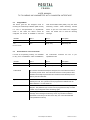
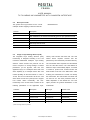
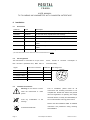

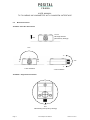
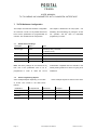

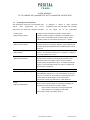
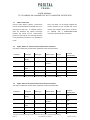
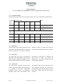

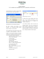


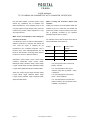

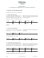
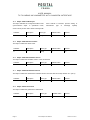

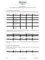


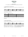
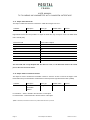


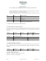
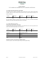


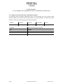
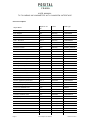
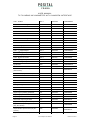

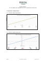
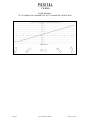


![Final Report - [Almost] Daily Photos](http://vs1.manualzilla.com/store/data/005658230_1-ad9be13b69bd4f2e15f58148160b0f22-150x150.png)