1
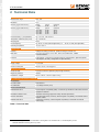
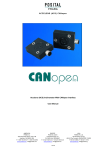
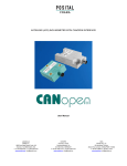
User Manual Inclination Sensors with CANopen Interface Version: 1.1 Date: 2011-07-01 GEMAC - Gesellschaft für Mikroelektronikanwendung Chemnitz mbH Zwickauer Straße 227 09116 Chemnitz Germany Telephone: Telefax: E-mail: Web: +49 371 3377 - 0 +49 371 3377 - 272 [email protected] www.gemac-chemnitz.de Revision History Revision History Date Revision Changes 2010-09-14 0 preliminary 2011-07-01 1 first version © Copyright 2011 GEMAC - Gesellschaft für Mikroelektronikanwendung Chemnitz mbH This document is subject to change without notice. We constantly work to further develop our products. We reserve any changes of the scope of delivery in shape, equipment and technology for ourselves. No claims can be made from the details, illustrations and descriptions in this document. Any kind of duplication, reprocessing and translation of this document as well as excerpts from it require the written permission of GEMAC mbH. All rights according to the copyright remain explicitly reserved for GEMAC mbH. Note: To use the inclination sensor, and for proper understanding of this manual, general knowledge of the field bus systems CAN and CANopen is required. Document: 231xx-HB-1-1-E-ISxDxxP21 I Table of Contents Table of Contents 1 Overview...................................................................................................................................................... 1 1.1 Characteristics..................................................................................................................................... 1 1.2 Applications.......................................................................................................................................... 1 2 Technical Data............................................................................................................................................. 2 3 Mounting...................................................................................................................................................... 4 3.1 Position of Drilling Holes...................................................................................................................... 4 3.2 Definition of the Axes........................................................................................................................... 4 4 Connection................................................................................................................................................... 5 4.1 Connector Pin Out............................................................................................................................... 5 4.2 Bus-Termination Resistor..................................................................................................................... 5 5 Function Description.................................................................................................................................... 6 5.1 Overview of Function........................................................................................................................... 6 6 CANopen Interface...................................................................................................................................... 7 6.1 CANopen Structure.............................................................................................................................. 7 6.2 CANopen Device Model....................................................................................................................... 7 6.3 COB-IDs.............................................................................................................................................. 7 6.4 Network Management: NMT................................................................................................................ 8 6.5 Process Data: PDO (TPDO1).............................................................................................................. 8 6.5.1 PDO Communication Types......................................................................................................... 9 6.5.1.1 Individual Request (Polling).................................................................................................. 9 6.5.1.2 Cyclic Transmission............................................................................................................. 9 6.5.1.3 Synchronous Transmission.................................................................................................. 9 6.5.1.4 Event-controlled transmission on inclination change (manufacturer specific)......................9 6.6 Service Data: SDO............................................................................................................................. 10 6.7 Object Dictionary................................................................................................................................ 10 6.7.1 Communication Parameters (according to CiA DS-301)............................................................11 6.7.1.1 Error Register (1001h)....................................................................................................... 12 6.7.1.2 Manufacturer Status Register (1002h)...............................................................................12 6.7.1.3 Pre-defined Error Field (1003h)......................................................................................... 13 6.7.1.4 Saving (1010h) and Loading (1011h) of Parameters..........................................................13 6.7.1.5 Transmit PDO1 – Transmission Type (1800h )..................................................................13 6.7.2 Manufacturer Specific Part......................................................................................................... 14 6.7.2.1 Automatic Bus-Off Recovery (2002h).................................................................................14 6.7.2.2 Cut-off Frequency of the Digital Filter (3000h)...................................................................14 6.7.2.3 TPDO1 Transmission on Inclination Change (3001h)........................................................14 6.7.3 Device Profile Specific Part (according to CiA DS-410).............................................................15 6.7.3.1 Resolution (6000h)............................................................................................................. 15 6.7.3.2 Inclination values longitudinal and lateral (6010h and 6020h)............................................15 6.7.3.3 Operating Parameters (6011h and 6021h).........................................................................16 Document: 231xx-HB-1-1-E-ISxDxxP21 II Table of Contents 6.7.3.4 Zero Point Adjustment: Preset Value, Offset Value, Differential Offset Value (60x1/2/3h). .16 6.8 Emergency Objects............................................................................................................................ 17 6.9 Failure monitoring.............................................................................................................................. 18 6.9.1 Nodeguarding / Lifeguarding...................................................................................................... 18 6.9.2 Heartbeat................................................................................................................................... 18 6.10 LSS: Layer Setting Service (according to CiA DSP-305)..................................................................19 6.10.1 Setting of Node-ID and Baud Rate........................................................................................... 19 6.11 Automatic Baud Rate Detection (according to CiA AN-801).............................................................19 6.12 Status LED (according to CiA DR-303-3)......................................................................................... 20 7 Sensor configuration.................................................................................................................................. 21 7.1 Inclination sensor programming adapter............................................................................................ 21 7.2 PC software ISDControl..................................................................................................................... 22 8 Ordering Information.................................................................................................................................. 23 Document: 231xx-HB-1-1-E-ISxDxxP21 III List of Tables List of Tables Table 1: Technical Data................................................................................................................................... 2 Table 2: Electromagnetic Compatibility (EMC)................................................................................................ 3 Table 3: Calculation of the COB-IDs for Pre-defined Connection Set..............................................................8 Table 4: TPDO1 Default mapping Type: IS1D 00 P21.....................................................................................9 Table 5: TPDO1 Default mapping Type: IS2D 90 P21.....................................................................................9 Table 6: Communication Parameters in the Object Dictionary......................................................................12 Table 7: Error Register (1001h)..................................................................................................................... 12 Table 8: Manufacturer Status Register (1002h)............................................................................................. 13 Table 9: Error Entry in Pre-defined Error Field (1003h).................................................................................13 Table 10: Transmit PDO1 - Transmission Type (1800h/02h).........................................................................14 Table 11: Manufacturer Specific Part of the Object Dictionary.......................................................................14 Table 12: Device Profile Specific Part of the Object Dictionary.....................................................................15 Table 13: Operating Parameters (6011h and 6021h)....................................................................................16 Table 14: Zero Point Adjustment................................................................................................................... 16 Table 15: Emergency Object......................................................................................................................... 17 Table 16: Emergency Error Codes................................................................................................................ 17 Table 17: Emergency: Manufacturer Specific Error Field..............................................................................17 Table 18: LSS Baud Rate Index according to CiA DSP-305..........................................................................19 Table 19: Status and Error Display through Two-Color LED..........................................................................20 Table 20: Ordering Information...................................................................................................................... 23 Document: 231xx-HB-1-1-E-ISxDxxP21 IV List of Figures List of Figures Figure 1: Dimensioned Sketch of plastic housing........................................................................................... 4 Figure 2: Definition of the Axes (factory default settings)................................................................................4 Figure 3: Connector Pin Out CAN Bus............................................................................................................ 5 Figure 4: CANopen Structure.......................................................................................................................... 7 Figure 5: NMT State diagram.......................................................................................................................... 8 Figure 6: SDO Protocol – Access to Object Dictionary..................................................................................10 Figure 7: Starter kit....................................................................................................................................... 21 Figure 8: PC software................................................................................................................................... 22 Document: 231xx-HB-1-1-E-ISxDxxP21 V Term and Abbreviation Definition Term and Abbreviation Definition Baud rate Speed of data transfer (1 Baud = 1 Bit/s) BOOL Data type BOOLEAN (8 Bit, 0 = FALSE, 1 = TRUE) CAN Controller Area Network CANopen Standardized application layer for CAN devices CiA CAN in Automation e.V. CiA DS CiA Draft Standard (specification published by CiA) CiA DS-301 Specification of the CANopen application layer and the communication parameters in the OD CiA DP CiA Device Profile (device profile published by CiA) CiA DR CiA Draft Recommendation (recommended implementation published by CiA) CiA DR-303-3 Recommended implementation for display of CANopen-device states and errors by LED(s) CiA DSP Draft Standard Proposal (specification draft published by CiA) CiA DSP-410 Specification draft of the device profile 410 for inclination sensors Client CANopen station which claims the service of a server COB CANopen Communication Object COB-ID CAN-Identifier of a COB DOMAIN Data type DOMAIN (arbitrary large block of data, e.g. program code) EDS Electronic Data Sheet (of a CANopen device) EMCY Emergency Object (Object that informs of errors) ...h Hexadecimal value xxxxh/xxh Index/Subindex, position of an OD parameter Heartbeat Surveillance mechanism for CANopen stations ID Identifier of a CAN message INT8 Data type INTEGER8 (8 Bit, complement on two, -128...127) INT16 Data type INTEGER16 (16 Bit, two's complement, -32768...32767) lateral Axis assignment (Y-axis) longitudinal Axis assignment (X-axis) LSS Layer Setting Service NMT Network Management Object (Object to set and check CANopen device states) Node-ID Node number of a CANopen device (1...127) Node- / Lifeguarding Surveillance mechanism for CANopen stations Operational CANopen device state (SDO, PDO, EMCY, NMT possible) OD Object dictionary (virtual directory with device parameters, addressed by index and subindex) PDO Process Data Object (Object for transfer of process data without protocol offset) PDO Mapping Sequence in which process data is arranged in a PDO Pre-Operational CANopen device state (SDO, EMCY, NMT possible) Pre-defined Connec tion Set In CiA DS-301 defined concept how COB IDs of the communication objects have to be calculated in de pendence of the Node ID ro Read only, access right „read only“ of an object in the object dictionary RTR Remote Transmit Request, Bit within a CAN-Frame which induces the recipient to send data rw Write and read, access right „write and read“ of an object in the object dictionary SDO Service Data Object (object for access to the object dictionary) Server CANopen station which offers a service for one/several client(s) Stopped CANopen device state (only NMT possible) UNS8 Data type UNSIGNED8 (8 Bit, without sign, 0...255) UNS16 Data type UNSIGNED16 (16 Bit, without sign, 0...65535) UNS32 Data type UNSIGNED32 (32 Bit, without sign, 0...4294967296) Document: 231xx-HB-1-1-E-ISxDxxP21 VI Term and Abbreviation Definition VSTR Data type VISIBLE STRING (ASCII-string inclusive end identifier 0h) wo write only, access right „write only“ of an object in the object dictionary Document: 231xx-HB-1-1-E-ISxDxxP21 VII 1 Overview 1 Overview 1.1 Characteristics 1-dimensional inclination sensors with measurement range: 360° (±180°) 2-dimensional inclination sensors with measurement range: ±90° (X/Y) High sampling rate and bandwidth High resolution (0.01°) and accuracy (0.05°) Compensated cross sensitivity Programmable vibration suppression Comfortable CANopen interface Meets the CiA DS-301, device profile CiA DSP-410 Baud rates from 10 kBit/s to 1 MBit/s Automatic baud rate detection Setting Node ID and baud rate via LSS service Functions: One TPDO dynamically mappable (RTR, cyclic, event-controlled, synchronized) SYNC Consumer (synchronized transmission of the TPDO after receiving a SYNC message) EMCY Producer Failure monitoring via Heartbeat or Nodeguarding / Lifeguarding Robust, UV resistant, impact strength plastic housing Suitable for industrial use: Temperature range plastic housing: -40 °C to +80 °C Degree of protection: IP65/67 The inclination sensor IS1D 00 P21 is suitable to measure the inclination in the measurement range of 360°. The 2-dimensional inclination sensor IS2D 90 P21 is suitable to measure the inclination in 2 dimensions (X/Y) in the measurement range of 90°. To ensure a high accuracy, the sensors are calibrated at the factory. The compact and robust design makes the sensor a suitable angle measurement device in rough surround ings for different applications in industry and automotive technology. A simple setting of all parameters which are stored in the internal permanent memory is possible via CAN bus interface. 1.2 Applications Solar thermal and photo-voltaic systems Agricultural and forestry machinery Construction machinery Crane and hoisting technology Document: 231xx-HB-1-1-E-ISxDxxP21 1 2 Technical Data 2 Technical Data General Parameters1 Measurement range 360°, ±90° Resolution 0.01° Accuracy (Type: IS1D 00 P21) Range 0...360° typical ±0.04° maximum ±0.10° Accuracy (Type: IS2D 90 P21) Range up to ±60° up to ±70° up to ±80° up to ±85° typical ±0.02° ±0.04° ±0.08° ±0.16° maximum ±0.05° ±0.10° ±0.20° ±0.40° Cross Sensitivity*** (compensated) typ. ±0.10 %, max. ±0.50 % Temperature coefficient (zero point) typ. ±0.008 °/K Sampling rate 80 Hz Cut-off frequency typ. 20 Hz, 2nd order (without digital filter) / 0.1 ... 25 Hz, 8th order (with digital filter) Operating temperature -40 °C to +80 °C Characteristics Interface CANopen according CiA DS-301, profile according to CiA DSP-410 Data rates 10 k, 20 k, 50 k, 62.5 k, 100 k, 125 k, 250 k, 500 k, 800 k Bit/s, 1 MBit/s automatic detection Functions Angle request, cyclical and synchronized outputs, parametrization, digital filter (Butter worth lowpass, 8th order), configuration via object dictionary Electrical Parameters Supply voltage 8 to 48 VDC Current consumption 86 mA to 19 mA, <33 mA @ 24 V Mechanical Parameters Connector CAN 2x sensor connector 5-pole M12 (loop through connector) Degree of protection IP65/67 Dimensions / Weight 66 mm x 90 mm x 36 mm / approx. 215 g CE conformity to EC Directive 2006/42/EC EC Directives RL 2004/108/EC EMC Directive RL 2006/95/EC Low Voltage Directive (LVD) Harmonized standards DIN EN 50498:2010 Electromagnetic compatibility (EMC) - Product family standard for aftermarket electronic equipment in vehicles EN 60950-1:2006/A1:2010 Information technology equipment. Safety. General requirements EN ISO 14982:2009 Agricultural and forestry machinery. Electromagnetic compatibility. Test methods and ac ceptance criteria DIN EN 13309:2010 Construction machinery - Electromagnetic compatibility of machines with internal power supply Table 1: Technical Data 1 All indicated angle accuracies are valid after a running time of 10 minutes at 25 °C, Cut-off frequency 0.3 Hz Absolute calibration accuracy (at 25 °C): ±0.05° Document: 231xx-HB-1-1-E-ISxDxxP21 2 2 Technical Data Electromagnetic Compatibility (EMC) Transient Emissions Radiated disturbance / Radio field strength Limit curves broadband and narrowband EN ISO 14982 (agricultural and forestry machinery) respectively EN ISO 13309 (construction machinery) 30 ... 1000 MHz (vertical and horizontal) Immunity to Radio Frequency Fields (RF fields) Strip line according to ISO 11452-5 Limits according to EN ISO 14982 (agricultural and forestry machinery) respectively EN ISO 13309 (construction machinery) 20 ... 400 MHz 200 V/m (1 KHz AM) Performance criteria A Anechoic chamber according to ISO 11452-2 Limits according to EN ISO 14982 (agricultural and forestry machinery) respectively EN ISO 13309 (construction machinery) 200 ... 1000 MHz vertical / 400 ... 1000 MHz horizontal 100 V/m (1 KHz AM) Performance criteria A Immunity to Conducted Disturbances (on-board power supply 24 VDC) Test pulse according to ISO 7637-2:2004 Test pulse 1 -450 V 2a +37 V 2b +20 V 3a -150 V 3b +150 V 4 -12 V 5a +70 V 5b +36 V Severity level III III III III III III Ri = 1 Ω Ri = 0,5 Ω Performance criteria C B C A A B A A Immunity to Electromagnetic Discharge (ESD) ESD according to ISO 10605:2008 Limits according to EN ISO 14982 (agricultural and forestry machinery) respectively EN ISO 13309 (construction machinery) discharge combination 330 pF / 330 Ω Contact discharge 8 KV bipolar (metallic parts) Air discharge 15 KV bipolar Performance criteria A Table 2: Electromagnetic Compatibility (EMC) Document: 231xx-HB-1-1-E-ISxDxxP21 3 3 Mounting 3 Mounting 3.1 Position of Drilling Holes The four drilling holes to mount the sensor (Figure 1) are situated in the base plate of the inclination sensor. Figure 1: Dimensioned Sketch of plastic housing 3.2 Definition of the Axes Figure 2: Definition of the Axes (factory default settings) Document: 231xx-HB-1-1-E-ISxDxxP21 4 4 Connection 4 Connection 4.1 Connector Pin Out The inclination sensors IS1D 00 P21 and IS2D 90 P21 are equipped with a common 5-pole round plug M12 (A-coded). The pin allocation fulfills CiA DR-303-1 (Figure 3). Pin Signal Allocation 1 CAN_SHLD Shield 2 CAN_V+ Supply voltage (+24 V) 3 CAN_GND GND / 0 V / V- 4 CAN_H CAN_H bus line 5 CAN_L CAN_L bus line Figure 3: Connector Pin Out CAN Bus 4.2 Bus-Termination Resistor The inclination sensors contain no internal termination resistor. Document: 231xx-HB-1-1-E-ISxDxxP21 5 5 Function Description 5 Function Description 5.1 Overview of Function The inclination sensors IS2D xx P06 / P07 contain a standardized CANopen interface according to CiA DS-301 and a device profile according to CiA DSP-410. All measured values and parameters are ac cessible through the object dictionary (OD). The individual configuration can be saved in the internal per manent memory (EEPROM). The following CANopen functions are available: One transmission data object (TPDO1) dynamically mappable in four possible operating modes: Individual request via remote transmit request message frame (RTR) Cyclic transmission at defined intervals Event-controlled transmission on inclination change Synchronous transmission after receiving a SYNC message frame One Service Data Object (Default SDO) Error messages by Emergency Object (EMCY) with support of the General Error Register Manufacturer specific status register (Manufacturer Status) List of errors (Pre-defined Error Field) Heartbeat and Nodeguarding / Lifeguarding monitoring mechanisms Store and load function of all parameters (Store and Load Parameter Field) Condition and error information by two-colored LED (according to CiA DR-303-3) Further manufacturer and profile specific characteristics exist in addition to the CiA DS-301 functionality: Configurable cut-off frequency (digital filter) Configuration of the minimum angle change for TPDO1 transmit event Direction switch of the inclination value Configurable zero point of the inclination value Setting of the Node-ID as well as the baud rate via LSS service according to CiA DSP-305 Automatic baud rate detection according to CiA AN-801 Document: 231xx-HB-1-1-E-ISxDxxP21 6 6 CANopen Interface 6 CANopen Interface 6.1 CANopen Structure CANopen is a CAN-based open protocol standard in automation and was standardized in association with “CAN in Automation” (CiA). Like virtually all field buses CANopen is based also on the ISO/OSI 7-layer mod el. The protocol makes use of the CAN bus as a transmission medium and defines the elements for network management, the use of the CAN identifier (message address), the temporal behavior on the bus, the type of data transfer and application profiles. This is to ensure that CANopen devices from different manufactur ers can be combined. Profile IO Profile Motion Profile Inclinometer Device-, Application Profile CiA DS-4xx other Profiles ISO/OSI Layer 7: Application Layer Communication Profile CiA DS-301 ISO/OSI Layer 2: Data Link Layer CAN ISO/OSI Layer 1: Physical Layer Standard ISO 11898 CAN Figure 4: CANopen Structure CANopen describes the ISO / OSI layer 7 (application layer) as a communication profile that was specified in the CiA standard CiA DS-301. The standard defines the method of communication for all devices consist ently. In addition, more device and application profiles for specific classes of devices and applications in the CiA standard DS-4xx are defined. 6.2 CANopen Device Model The exchange of data between CANopen devices is realized via data objects. The CANopen communica tion profile thus provides for the following types of objects. The process data objects (PDO) are high-priority messages used for the exchange of process data. Access to the object dictionary of a device is done via the service data objects (SDOs). Network management objects are used to control the state machine of the CANopen device and to monitor the nodes. Furthermore, there are special objects for error messages (Emergency), Synchronization (SYNC) and time stamp. Every CANopen device has a CANopen object dic tionary, in which the parameters for all CANopen objects are registered. Document: 231xx-HB-1-1-E-ISxDxxP21 7 6 CANopen Interface 6.3 COB-IDs The CAN identifier of the communication objects is determined according to the Pre-defined connection set at each reset (communication, application and hardware reset), depending on the selected Node-ID. Table 3 shows the calculation base with the default values (Node-ID = 10). Communication object (COB) Calculation of the COB-ID Default value (Node-ID = 10) NMT 0h 0h SYNC 80h 80h EMCY 80h + Node-ID 8Ah TPDO1 180h + Node-ID 18Ah Default SDO (Client > Server) 600h + Node-ID 60Ah Default SDO (Server > Client) 580h + Node-ID 58Ah Heartbeat 700h + Node-ID 70Ah Table 3: Calculation of the COB-IDs for Pre-defined Connection Set 6.4 Network Management: NMT Figure 5 shows the NMT state machine of a CANopen device. After Initialization the device automatically goes into the state Pre-Operational. The device sends a Boot-Up Message. In this state it can be con figured via the object dictionary. The service data objects (SDO) are already active. The process data ob jects, however, are still locked. Initialization Automatic Baud Rate Detection Boot-Up Message Pre-Operational Stopped Operational Figure 5: NMT State diagram By sending the CAN message "Start Remote Node" the unit will go into the state Operational. Now the pro cess data objects are active. In Stopped state, no communication with the exception of Nodeguarding and Heartbeat is possible. Document: 231xx-HB-1-1-E-ISxDxxP21 8 6 CANopen Interface 6.5 Process Data: PDO (TPDO1) Each inclination sensor has exactly one transmit process data object (TPDO). The TPDO contains the cur rent values of inclination (axial or longitudinal and lateral). The PDO mapping of the measured values is dy namically adjusted. The default mapping is shown inTable 4/5. Data part of the CAN Frame of the TPDO1 Byte0 Byte1 Byte2 Byte3 Byte4 Inclination value axial (OV: 6010h) Byte5 Byte6 Byte7 Byte6 Byte7 unused Table 4: TPDO1 Default mapping Type: IS1D 00 P21 Data part of the CAN Frame of the TPDO1 Byte0 Byte1 Inclination value longitudinal (X-Axis, OV: 6010h) Byte2 Byte3 Byte4 Inclination value lateral (Y-Axis, OV: 6020h) Byte5 unused Table 5: TPDO1 Default mapping Type: IS2D 90 P21 6.5.1 6.5.1.1 PDO Communication Types Individual Request (Polling) The TPDO1 can be requested at any time by transmitting a remote-transmit request message frame. 6.5.1.2 Cyclic Transmission The cyclic transmission of the TPDO1 is activated if the entry 1800h/05h (interval time in milliseconds) con tains a value greater than 0. Furthermore, the entry 1800h/02h (transmission type) must contain the value 254 (asynchronous, manufacturer-specific). In this case, the inclination sensor will transmit the TPDO1 cyc lically at the set period interval when in the OPERATIONAL state. 6.5.1.3 Synchronous Transmission The synchronous transmission is used to get inclination values from more then one sensor at the same time. Therefore CANopen provides a SYNC object - a CAN message without user data - transmitted with high priority on the bus. This SYNC object is transmitted from a bus node (usually the master) cyclically at fixed intervals. All inclination sensors read their current value after every n th reception of the SYNC object and then transmit the TPDO1 directly as soon as the bus permits. For this the entry 1800h/02h (Transfer Type) must contain the value n = 1...240. 6.5.1.4 Event-controlled transmission on inclination change (manufacturer specific) The bus load from PDOs can be reduced if the TPDO1 is only transmitted when an appropriate angle change has occurred. This function can only be configured in the manufacturer-specific part of the object directory under index 3001h. To this end, the entry 1800h/02h (transmission type) must contain the value 254 (asynchronous, manufacturer-specific). Document: 231xx-HB-1-1-E-ISxDxxP21 9 6 CANopen Interface 6.6 Service Data: SDO The parameters, listed in the object dictionary, are read and written through Service Data Objects (SDOs). As shown in Table 6, every object can directly be addressed over a 16-bit index. In addition, each index has an 8-bit subindex that allows an additional choice within an index. The 8 bytes of the SDOs are placed in the data area of the CAN message. Byte0 Byte1...3: Addressing Command Specifier - Upload - Download - Data byte count - Request - Response - Abort 16 Bit Index Byte4...7: 1...4 Byte Parameter 8 Bit Subindex O b j Data0 e Data1 c t Data2 D i Data3 c t i o n a Index Subindex Description Parameter 1000h 00h Device Type 2019Ah ... ... ... ... 1018h 00h Identity Object 04h 01h Vendor ID 0159h 02h Product Code 5A72h (23154dec) 03h Revision number 00000001h 04h Serial number 12345678h ... ... Slope Long16 1599 (15,99°) ... ... ... ... 6010h 00h ... ... r y Figure 6: SDO Protocol – Access to Object Dictionary 6.7 Object Dictionary The object directory contains all data objects that are accessible from the outside and affect the behavior of communication, application and status machines. It is divided into three parts: Communication specific Part (Index: 0x1000 – 0x1FFF) Manufacturer specific Part (Index: 0x2000 – 0x5FFF) Profile specific Part (Index: 0x6000 – 0x9FFF) All parameters in the object dictionary can be read and written using the standard SDO via index and su bindex. The following sections describe all the parameters in the object dictionary of the inclination sensor with in dex, subindex, data type, access rights and default (factory setting). The column "Save" indicates whether a parameter in the internal volatile memory ("save" signature in OD-Write Index 1010h/01h) can be saved. Document: 231xx-HB-1-1-E-ISxDxxP21 10 6 CANopen Interface 6.7.1 Index Communication Parameters (according to CiA DS-301) Su Parameter bInd ex Data Type Ac cess Default Value 1000h 0 Device Type (Device profile 410), Type IS1D 00 P21 / IS2D 90 P21 UNS32 1001h 0 Error Register UNS8 ro 0 1002h 0 Manufacturer Status Register UNS32 ro 0 Number of Errors entries UNS32 rw 0 Error Code (oldest error on highest index) UNS32 ro 0 Save const 1019Ah/2019Ah 1003h Pre-defined Error Field 0 1..5 1005h 0 COB-ID Sync Message UNS32 rw 80h 1008h 0 Manufacturer Device Name VSTR const {dep. on type} 100Ah 0 Manufacturer Software Version („Vxx.yy“) VSTR const {dep. on type} 100Ch 0 Guard Time (Multiple of 1 ms) UNS16 rw 0 x 100Dh 0 Life Time Factor UNS8 rw 0 x 1010h Store Parameters (Signature: 's','a','v','e' - 65766173h at SubIndex 1...4) 0 Largest supported SubIndex UNS32 ro 4 1 Save all Parameters (OV: 0x1000-0x9FFF) UNS32 rw 1 2 Save Communication Parameters (OV: 0x1000-0x1FFF) UNS32 rw 1 3 Save Application Parameters (OV: 0x6000-0x9FFF) UNS32 rw 1 4 Save Manufacturer Parameters (OV: 0x2000-0x5FFF) UNS32 rw 1 UNS32 ro 4 1011h Restore Default Parameters (Signature: 'l','o','a','d' - 64616F6Ch at SubIndex 1...4) 0 Largest supported SubIndex 1 Restore all Default Parameters (OV: 0x1000-0x9FFF) UNS32 rw 1 2 Restore Communication Default Parameters (OV: 0x1000-0x1FFF) UNS32 rw 1 3 Restore Application Default Parameters (OV: 0x6000-0x9FFF) UNS32 rw 1 4 Restore Manufacturer Default Parameters (OV: 0x2000-0x5FFF) UNS32 rw 1 1014h 0 COB-ID Emergency Message UNS32 ro 80h + Node-ID 1015h 0 Inhibit Time Emergency (multiple of 100 µs) UNS16 rw 0 x 1017h 0 Producer Heartbeat Time (multiple of 1 ms, 0 inactive) UNS16 rw 0 x 4 1018h Identity Object 0 Largest supported SubIndex UNS8 ro 1 Vendor-ID (Manufacturer ID: GEMAC mbH) UNS32 ro 159h 2 Product Code UNS32 ro {dep. on type} 3 Revision number UNS32 ro {dep. on type} 4 Serial number UNS32 ro {dep. on type} 1200h Server SDO1 Parameter 0 Largest supported SubIndex UNS8 ro 2 1 COB-ID Client > Server UNS32 ro 600h + Node-ID 2 COB-ID Server > Client UNS32 ro 580h + Node-ID UNS8 ro 5 1800h Transmit PDO1 Communication Parameter 0 Largest supported SubIndex 1 COB-ID UNS32 ro 180h + Node-ID 2 Transmission Type (synchronous / asynchronous manufacturer specific) UNS8 rw 1 x 3 Inhibit Time between two TPDO Messages (multiple of 100 µs) UNS16 rw 0 x 4 Compatibility Entry UNS8 rw 0 x Document: 231xx-HB-1-1-E-ISxDxxP21 11 6 CANopen Interface 5 Event Timer (Multiple of 1 ms, 0 inactive) UNS16 rw 0 x {dep. on type} 1A00h Transmit PDO1 Mapping Parameter 0 Largest supported SubIndex UNS8 ro 1 Mapping Entry 1, both types: IS1D 00 P21 / IS2D 90 P21 UNS8 rw 0x60100010 x 2 Mapping Entry 2, Type: IS1D 00 P21 / IS2D 90 P21 UNS8 rw 0 / 0x60200010 x 3 Mapping Entry 3 UNS8 rw 0 x 4 Mapping Entry 4 UNS8 rw 0 x 5 Mapping Entry 5 UNS8 rw 0 x 6 Mapping Entry 6 UNS8 rw 0 x 7 Mapping Entry 7 UNS8 rw 0 x 8 Mapping Entry 8 UNS8 rw 0 x 1F50h Download Program Data 0 Largest supported SubIndex DOMAIN ro 3 1 Area Firmware DOMAIN wo - 2 Area Configuration 1, (Access only to manufacturers) DOMAIN wo - 3 Area Configuration 2, (Access only to manufacturers) DOMAIN wo - 1F50h Download Program Control 0 Largest supported SubIndex UNS8 ro 3 1 Area Firmware UNS8 rw 1 2 Area Configuration 1, (Access only to manufacturers) UNS8 rw 1 3 Area Configuration 2, (Access only to manufacturers) UNS8 rw 1 Table 6: Communication Parameters in the Object Dictionary 6.7.1.1 Error Register (1001h) The error register displays the general error state of the device. Each bit stands for an error group. If one bit is set (= 1), at least one error of that specific group occurs. The content of this register is transmitted in each EMCY object. The following error groups can occur: Error Register (1001h) Bit7 Bit6 Bit5 Bit4 Manufacturer Specific Error Unused Profile Specific Error Communication Error Bit3 Bit2 Unused Bit1 Bit0 At least one active fault Table 7: Error Register (1001h) If the device is in error state (at least one active error) this is shown by the set Bit0 (= 1). In the event of a communication error (overflow of the transmit / receive buffers, guarding errors or CAN controller in the passive mode / Bus-Off) the Bit4 is set. A device profile specific error (sensor error) is shown by Bit5. The Bit7 indicates a vendor-specific error (EEPROM error). 6.7.1.2 Manufacturer Status Register (1002h) This Register shows the recent state of all detectable errors. Here each bit represents a specific error. If a bit is set (= 1), this error is active at that moment. The low ordered 16 bits of this register (Bit15...Bit0) are transmitted in the first two bytes of the manufacturer specific part of each EMCY object and are also re gistered in the additional information field (Bit31-Bit16) of the Pre-defined Error Field 1003h. The definitions of the individual bits in the bit fields "Device Error" and "Communication Error" are shown in Table 17. Document: 231xx-HB-1-1-E-ISxDxxP21 12 6 CANopen Interface Manufacturer Status Register (1002h) Bit31...Bit16 Bit15...Bit8 Bit7...Bit0 Unused Bit field Communication Error Bit field Device Error Table 8: Manufacturer Status Register (1002h) 6.7.1.3 Pre-defined Error Field (1003h) Each inclination sensor has an error list holding the last five errors. The list 1003h/00h contains the number of error entries in the error field. The other subindices contain all occurred error states in chronological or der. The last occurred error is always located at SubIndex 01h. The oldest error can be found in the largest available SubIndex (value of 1003h/00h) and will be the first to be deleted from the list with occurrence of more than five errors. If a new error occurs a new error entry is added in 1003h and is also notified by an EMCY object. An error entry is structured as follows: Error Entry in Pre-defined Error Field (1003h) Additional Information Field (Bit31...Bit16) Bit15...Bit0 of the manufacturer status register 1002h (at the moment of error occurrence) Bit field Communication error Bit field Device Error Error Code (Bit15...Bit0) 0x0000 0x5010 0x5020 0x8110 0x8120 0x8130 0x8140 Error reset or no error present Sensor Error / Sensor Error X Sensor Error Y Overflow of the transmit / receive buffers CAN Warning Limit reached Node Guard Event Recovered from Bus-Off Table 9: Error Entry in Pre-defined Error Field (1003h) The error list can be reset completely by writing 0 to entry 1003h/00h. 6.7.1.4 Saving (1010h) and Loading (1011h) of Parameters If parameters are changed in the object dictionary those changes will take effect immediately. To ensure the changed parameters are still active after Reset they have to be saved in the internal EEPROM. By writing the signature „save“ (65766173h) to the entry 1010h/01h all the current parameters of the object dictionary will be saved in the internal permanent memory. The object dictionary can be reset to its default settings by writing the signature „load“ (64616F6Ch) into the entry 1011h/01h. By doing this the factory parameters are written in the permanent memory. After a „Reset Application“ (NMT command) or a hardware reset the changes will take effect (a „Reset Communication“ (NMT command) effects the communication parameters only). By writing the signature on SubIndex: 02h, 03h or 04h, it is possible to store or load only parts of the object directory. 6.7.1.5 Transmit PDO1 – Transmission Type (1800h ) The entry 1800h/02h can be used to define how the transmission of the PDO is triggered. Document: 231xx-HB-1-1-E-ISxDxxP21 13 6 CANopen Interface Transmit PDO1 - Transmission Type (1800h/02h) Transmission Type Description 1...240 Synchronous (cyclic) Transmission after each 1...240 reception of a SYNC message only „Synchronized Transmission“ via SYNC possible 253 Transmission with RTR only 254 Asynchronous, manufacturer-specific „Cyclic Transmission“ and/or „Transmission on Inclination Change“ activated by appropriate configuration Table 10: Transmit PDO1 - Transmission Type (1800h/02h) 6.7.2 Index Manufacturer Specific Part Su Parameter bInd ex Data type Ac cess Default value Save 2002h 0 Automatic Bus-Off Recovery BOOL rw 0 x 3000h 0 Cut-off frequency digital filter (0 = deactivated or 100...25000, in mHz) UNS16 rw 2000 x 3001h TPDO1 Transmission on Inclination Change, Type IS1D 00 P21 0 Largest supported SubIndex UNS16 ro 2 1 Enable/Disable (1/0) transmission on inclination change UNS16 rw 0 x 2 Minimum inclination change for axial axis (multiple of °/100) UNS16 rw 100 x 3001h TPDO1 Transmission on Inclination Change, Type IS2D 90 P21 0 Largest supported SubIndex UNS16 ro 3 1 Enable/Disable (1/0) transmission on inclination change UNS16 rw 0 x 2 Minimum inclination change for longitudinal (X) axis (multiple of °/100) UNS16 rw 100 x 3 Minimum inclination change for lateral (Y) axis (multiple of °/100) UNS16 rw 100 x 5555h Reserved index (access for manufacturer only) Table 11: Manufacturer Specific Part of the Object Dictionary 6.7.2.1 Automatic Bus-Off Recovery (2002h) This property determines the behavior of the inclination sensor when it is in the state Bus-Off. If enabled, the sensor, which is in Bus-Off state may become error-active (no longer Bus-Off) with its error counters both set to zero after having monitored one hundred and twenty-eight (128) occurrences of eleven (11) consecut ive recessive bits on the bus. If disabled, the inclination sensor remains in Bus-Off state. 6.7.2.2 Cut-off Frequency of the Digital Filter (3000h) The inclination sensor offers the possibility to suppress the influence of external disturbing vibrations. The internal low pass digital filter (Butterworth, 8th order) is programmable down to 0.1 Hz. The cut-off frequency is adjustable between 0.1 and 25 Hz and can be set under 3000h. Values are allowed between 100 (= 0.1 Hz) and 25,000 (= 25 Hz). Cut-off frequency = 0 disables the digital filter. 6.7.2.3 TPDO1 Transmission on Inclination Change (3001h) Through the entry 3001h/01h the event controlled transmission of the TPDO1 on inclination change can be enabled (= 1) or disabled (= 0). For the activation the transmission type of TPDO1 must be set to “Asyn chronous, manufacturer-specific” (1800h/02h = 254). Document: 231xx-HB-1-1-E-ISxDxxP21 14 6 CANopen Interface SubIndices 02h and 03h offer the separated setting of the minimum necessary inclination change for the longitudinal (X) and lateral (Y) axis. These two angle values are mentioned in °/100 (100fold angle value) and can be set freely from 1 = 0.01° to maximum. If this function is enabled the inclination sensor outputs the TPDO1 object in the state OPERATIONAL in case of inclination changes of the longitudinal and/or the lateral axis greater than set under 3001h/02h and 03h. During operation the angle difference between the recent inclination value and the last one sent by the TPDO1 is permanently calculated and checked. With each crossing to the state OPERATIONAL the inclina tion sensor posts the recent position by the TPDO1 object, too (only if 3001h/01h = 1). Remarks: If small inclination differences are set under 3001h/02h and 03h it is recommended to enable the digital filter (index 3000h) to reduce the influence of vibrations and the frequent output of the TPDO1. 6.7.3 Index Device Profile Specific Part (according to CiA DS-410) Su Parameter bInd ex Data type Ac cess Default value Save 6000h 0 Resolution (multiple of 0,001°) UNS16 ro 10 6010h 0 Inclination value longitudinal (X-axis, 100fold angle value in °) INT16 ro - 6011h 0 Operating Parameter longitudinal (Inversion, Zero Point Adjustment) UNS8 rw 0 x 6012h 0 Preset Value longitudinal (X) Axis INT16 rw 0 x 6013h 0 Offset Value longitudinal (X) Axis INT16 rw 0 x 6014h 0 Differential Offset Value longitudinal (X) Axis INT16 rw 0 x 6020h 0 Inclination value lateral (X-axis, 100fold angle value in °) INT16 ro - 6021h 0 Operating Parameter lateral (Inversion, Zero Point Adjustment) UNS8 rw 0 x 6022h 0 Preset Value longitudinal (Y) Axis INT16 rw 0 x 6023h 0 Offset Value longitudinal (Y) Axis INT16 rw 0 x 6024h 0 Differential Offset Value longitudinal (Y) Axis INT16 rw 0 x Table 12: Device Profile Specific Part of the Object Dictionary 6.7.3.1 Resolution (6000h) The resolution of all inclination sensors are set to 0.01° (default: 10 * 0.001°). All angle values in the object dictionary (6010h, 6012h, 6013h, 6014h and 6020h, 6022h, 6023h, 6024h) are to be interpreted as a mul tiple of 0.01 °. Example: Inclination value = -2370 x 0.01° → -23.70° 6.7.3.2 Inclination values longitudinal and lateral (6010h and 6020h) The recent inclination values of the inclination axes are accessible by SDO access to the object dictionary (in each device state) as well as by TPDO. If Zero Point Adjustment is enabled via the operating parameters 6011h and 6021h, the inclination value is calculated as follows: Inclination Value = Physically Measured Inclination Value + Diff. Offset Value + Offset Value Document: 231xx-HB-1-1-E-ISxDxxP21 15 6 CANopen Interface On disabled Zero Point Adjustment: Inclination Value = Physically Measured Inclination Value The conversion of the 100fold, signed 16-Bit inclination value (complement on two) is described in chapter 6.7.3.3 . Example: Value Range Type IS1D 00 P21: -18000 ... +17999 → -180,00° ... +179,99° = 0 ...359,99° Value Range Type IS2D 90 P21: 6.7.3.3 -9000 ... +9000 → - 90,00° ... + 90,00° Operating Parameters (6011h and 6021h) The operating parameters settings of an inclination sensor (6011h and 6021h) allow the changing of the mathematical sign of the inclination value and a Zero Point Adjustment. On Factory Default Settings, these options are disabled, i.e. the direction of the inclination value (polarity of the axis) corresponds to the one shown on the nameplate of the inclination sensor. Operating Parameters (6011h and 6021h) Bit7 Bit6 Bit5 Bit4 Bit3 Bit2 Bit1 Bit0 Zero Point Adjustment Inversion Unused 0 = /inactive 1 = active 0 = /inactive 1 = active Table 13: Operating Parameters (6011h and 6021h) 6.7.3.4 Zero Point Adjustment: Preset Value, Offset Value, Differential Offset Value (60x1/2/3h) Using the values “Preset Value”, “Offset Value” and “Differential Offset Value” the adjustment of the Zero Point is possible. The Zero Point Adjustment is only active if the Bit1 in the operating parameters (6011h/6021h) is set. Value Object Description Preset Value 6012h 6022h Preset Value for Zero Point Adjustment, value range depends on settings in object 6000h Offset Value 6013h 6023h Calculated Offset Value when writing to object 6012h or 6021 Calculated Offset Value = Preset Value at tacc – physically measured Inclination Value at tacc – Dif ferential Offset Value tacc: time when accessing object (6012h,6022h) Differential Offset Value 6014h 6024h Additional Offset, regardless of object 6012h and 6013h / 6022h and 6023h The value you enter here will be added up directly to the inclination value. Table 14: Zero Point Adjustment Document: 231xx-HB-1-1-E-ISxDxxP21 16 6 CANopen Interface 6.8 Emergency Objects Each inclination sensor supports EMCY objects which are transmitted in case of sensor and hardware er rors. If such an error occurs the OD entries 1001h (Error Register), 1002h (Manufacturer Status Register) and 1003h (Pre-defined Error Field) are updated. After abolishment of an error, the device transmits an emergency message with the Error Reset Code 0x0000. Yet current errors are signaled in Byte2 (Error Re gister) and Bytes 3,4 in the Manufacturer specific error field. Once the device is error-free, it sends an emer gency message which contains only zeros. The current state of the device (Pre-Operational, Operational or Stopped) is not influenced by the error states, except in case of a guarding error. Emergency messages are sent with high priority on the bus and are always 8 bytes long. The structure of the telegram is presented in Table 15: Emergency Object Byte0 Byte1 Emergency Error Code Byte2 Error Register (1001h) Byte3 Byte4 Byte5 Byte6 Byte7 Manufacturer Specific Error Field Bit field Communica tion Error Bit field Device Error 0x00 0x00 0x00 Table 15: Emergency Object Emergency Error Codes 0x0000 Error Reset or no Error (Error Register = 0) 0x5010 Sensor Error / Sensor Error X, Inclination value out of range 0x5020 Sensor Error Y, Inclination value out of range 0x8110 Overflow of the transmit / receive buffers, CAN messages were lost 0x8120 CAN Warning Limit reached 0x8130 Node Guard Event (The loss of the Guarding-Master has been detected) 0x8140 Recovered from Bus-Off Table 16: Emergency Error Codes Bit field Device Errors 0x01 Sensor Error type only: IS1D 00 P21 0x01 Sensor Error X-Axis type only: IS2D 90 P21 0x02 Sensor Error Y- Axis type only: IS2D 90 P21 0x80 EEPROM Error: An error occurred while saving the configuration. Bit field Communication Errors 0x01 CAN Warning Limit reached (too many Error Frames) 0x02 CAN Bus-Off State reached (An Emergency message will be transmitted after the device has recovered from Bus-Off) 0x04 Receive Queue Overrun, CAN messages were lost 0x08 Transmit Queue Overrun, CAN messages were lost 0x80 Guarding Error, The loss of the Guarding-Master has been detected. (Node Guard Event) Table 17: Emergency: Manufacturer Specific Error Field Document: 231xx-HB-1-1-E-ISxDxxP21 17 6 CANopen Interface 6.9 Failure monitoring Since the nodes do not respond at regular intervals with the event-controlled transmission in a CANopen network, Heartbeat and Nodeguarding / Lifeguarding failure monitoring mechanisms are provided. Only one of the two monitoring methods can be active. 6.9.1 Nodeguarding / Lifeguarding Nodeguarding is the monitoring of one or several nodes by the NMT master. The NMT master periodically issues an RTR message frame to the slave to be monitored, which responds with its status and with a toggle bit. If the status or the toggle bit do not comply with the status or toggle bit expected by the guarding master or if no response is provided, the master assumes a slave error. The node to be monitored can also use this mechanism to detect a failure of the guarding master. To this end, two parameters are used. The interval time after which the guarding master polls the inclination sensor to be monitored is the Guard Time (100Ch). Another parameter, the Life Time Factor (100Dh) defines a mul tiplier after which the connection is deemed to be interrupted. This time is designated as the node life time. „Node Life Time“ = „Guard Time“ x „Life Time Factor“ If the inclination sensor does not receive a guarding request from the master within the parametrized time, it also assumes a master failure, sends an emergency message frame and returns to the "Pre-Operational" state. If either of the two parameters is "0" (default setting), the master is not monitored (no Lifeguarding). 6.9.2 Heartbeat Heartbeat is a failure monitoring mechanism which can operate without using RTR message frames. In this case, the inclination sensor cyclically transmits a heartbeat message which contains the state of the device. The master can monitor these message frames. Heartbeat is activated once a value greater than "0" is entered in the heartbeat interval time register (1017h). Remarks: Heartbeat has a significant influence on the bus load of the CANopen network, but produces only half the high bus load of Nodeguarding / Lifeguarding. Document: 231xx-HB-1-1-E-ISxDxxP21 18 6 CANopen Interface 6.10 LSS: Layer Setting Service (according to CiA DSP-305) 6.10.1 Setting of Node-ID and Baud Rate The setting of the node address (Node-ID) and the Baud Rate is realized by the LSS (Layer Setting Service). For communication between LSS Master and LSS Slave (inclination sensor) two CAN identifiers (7E5h and 7E4h) are used. Each inclination sensor has a unique 128-bit LSS address, at which he can be addressed in the CAN network. This address is composed of the three 32-bit parameters of the Identity ob ject 1018h and the serial number: Vendor-ID 0000 0159h (Manufacturer ID: GEMAC mbH) Product Code 0000 5A72h (5A72h = 23154dec = PR-23154-30) Revision Number 0000 001Eh (1Eh = PR-23154-30) Serial Number xxxx xxxxh (respective serial number of the incl. sensor → nameplate) = 30dec The default values for Node-ID and Baud Rate at delivery (factory settings) are: Node-ID 10 Baud Rate Automatic Baud Rate Detection Index Baud Rate 0 1 MBit/s 1 800 kBit/s 2 500 kBit/s 3 250 kBit/s 4 125 kBit/s 5 unused 6 50 kBit/s 7 20 kBit/s 8 10 kBit/s 9 Automatic Baud Rate Detection Table 18: LSS Baud Rate Index according to CiA DSP-305 6.11 Automatic Baud Rate Detection (according to CiA AN-801) The automatic baud rate detection is used to automatically adjust the baud rate of the inclination sensor on the existing baud rate in the network. After power-on the inclination sensor only listen to the CAN network without acknowledging the received messages on the bus. This operating condition is characterized by the flickering of the RUN-LED (see also chapter: 6.12 „Status LED (according to CiA DR-303-3)“). The sensor checks all the available baud rates. Upon receipt of a valid CAN telegram, the correct baud rate is adjusted. Then he starts up in the mode Pre-Operational using a boot-up message. (see also Figure 5). Remarks: For proper operation of the automatic baud rate detection it is necessary to receive messages from other can nodes on the bus. Document: 231xx-HB-1-1-E-ISxDxxP21 19 6 CANopen Interface 6.12 Status LED (according to CiA DR-303-3) The integrated two-color Status LED signals the recent device state (Run LED, green) as well as CAN com munication errors that might have occurred (Error LED, red). The color and the flashing frequency of the LED distinguish the different device states as shown below. Status LED RUN LED LED State ERROR LED Legend: Description ... Off The device is in state Reset or no power supply is connected ... Flickering Automatic baud rate detection is currently running (active) ... Blinking The device is in state Pre-Operational ... Single Flash The device is in state Stopped ... On The device is in state Operational LED State LED off Description ... Off The device is in working condition ... Single Flash CAN Warning Limit reached ... Double Flash The loss of the Guarding-Master has been detected. (Node Guard Event) ... On The device is in state Bus-Off LED on LED flickering (50 ms on/off) Duration of / : 200 ms Table 19: Status and Error Display through Two-Color LED Document: 231xx-HB-1-1-E-ISxDxxP21 20 7 Sensor configuration 7 Sensor configuration 7.1 Inclination sensor programming adapter With the optional inclination sensor programming adapter (starter kit) it is possible to adjust all inclination sensors with CAN/CANopen, current or voltage interface. It consists of a programming adapter that is con nected via USB to a PC. The connection with the programming adapter is realized through various, also in cluded adapter cables. The inclination sensor is supplied with power through this. An additional power sup ply is not necessary. Figure 7: Starter kit Document: 231xx-HB-1-1-E-ISxDxxP21 21 7 Sensor configuration 7.2 PC software ISDControl The parametrization of all possible values is done with the PC software ISDControl, which is included in all starter kits. Each configuration can then be stored in a file. Features: Comfortable configuration of all parameters of the inclination sensor 3D imaging and display of the current angle Oscilloscope display of the current angle Firmware Download option Automatic inclination sensor search for unknown communication parameters Figure 8: PC software Document: 231xx-HB-1-1-E-ISxDxxP21 22 8 Ordering Information 8 Ordering Information Article Number Product Type Description/Distinction PR-23150-30 IS1D 00 P21 1-dimensional, 360°, CANopen interface PR-23154-30 IS2D 90 P21 2-dimensional, ±90°, CANopen interface PR-23999-01 ISPA1 Inclination sensor programming adapter (Starter kit including programming adapter, cables and PC software) Table 20: Ordering Information Document: 231xx-HB-1-1-E-ISxDxxP21 23