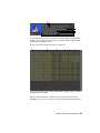
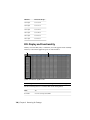
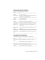
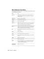
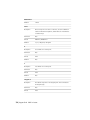
Download User Guide - Autodesk

Transcript
Autodesk
Lustre 2010
®
®
A Discreet systems product
®
User Guide
Autodesk® Lustre® 2010 Software
©
2009 Autodesk, Inc. All rights reserved. Except as otherwise permitted by Autodesk, Inc., this publication, or
parts thereof, may not be reproduced in any form, by any method, for any purpose.
Certain materials included in this publication are reprinted with the permission of the copyright holder.
Trademarks
The following are registered trademarks or trademarks of Autodesk, Inc., and/or its subsidiaries and/or affiliates in the USA and other countries:
3DEC (design/logo), 3December, 3December.com, 3ds Max, Algor, Alias, Alias (swirl design/logo), AliasStudio, Alias|Wavefront (design/logo),
ATC, AUGI, AutoCAD, AutoCAD Learning Assistance, AutoCAD LT, AutoCAD Simulator, AutoCAD SQL Extension, AutoCAD SQL Interface,
Autodesk, Autodesk Envision, Autodesk Intent, Autodesk Inventor, Autodesk Map, Autodesk MapGuide, Autodesk Streamline, AutoLISP, AutoSnap,
AutoSketch, AutoTrack, Backburner, Backdraft, Built with ObjectARX (logo), Burn, Buzzsaw, CAiCE, Civil 3D, Cleaner, Cleaner Central, ClearScale,
Colour Warper, Combustion, Communication Specification, Constructware, Content Explorer, Dancing Baby (image), DesignCenter, Design
Doctor, Designer's Toolkit, DesignKids, DesignProf, DesignServer, DesignStudio, Design Web Format, Discreet, DWF, DWG, DWG (logo), DWG
Extreme, DWG TrueConvert, DWG TrueView, DXF, Ecotect, Exposure, Extending the Design Team, Face Robot, FBX, Fempro, Fire, Flame, Flint,
FMDesktop, Freewheel, GDX Driver, Green Building Studio, Heads-up Design, Heidi, HumanIK, IDEA Server, i-drop, ImageModeler, iMOUT,
Incinerator, Inferno, Inventor, Inventor LT, Kaydara, Kaydara (design/logo), Kynapse, Kynogon, LandXplorer, Lustre, MatchMover, Maya,
Mechanical Desktop, Moldflow, Moonbox, MotionBuilder, Movimento, MPA, MPA (design/logo), Moldflow Plastics Advisers, MPI, Moldflow
Plastics Insight, MPX, MPX (design/logo), Moldflow Plastics Xpert, Mudbox, Multi-Master Editing, Navisworks, ObjectARX, ObjectDBX, Open
Reality, Opticore, Opticore Opus, Pipeplus, PolarSnap, PortfolioWall, Powered with Autodesk Technology, Productstream, ProjectPoint, ProMaterials,
RasterDWG, RealDWG, Real-time Roto, Recognize, Render Queue, Retimer,Reveal, Revit, Showcase, ShowMotion, SketchBook, Smoke, Softimage,
Softimage|XSI (design/logo), Sparks, SteeringWheels, Stitcher, Stone, StudioTools, Topobase, Toxik, TrustedDWG, ViewCube, Visual, Visual LISP,
Volo, Vtour, Wire, Wiretap, WiretapCentral, XSI, and XSI (design/logo).
All other brand names, product names or trademarks belong to their respective holders.
Disclaimer
THIS PUBLICATION AND THE INFORMATION CONTAINED HEREIN IS MADE AVAILABLE BY AUTODESK, INC. “AS IS.” AUTODESK, INC. DISCLAIMS
ALL WARRANTIES, EITHER EXPRESS OR IMPLIED, INCLUDING BUT NOT LIMITED TO ANY IMPLIED WARRANTIES OF MERCHANTABILITY OR
FITNESS FOR A PARTICULAR PURPOSE REGARDING THESE MATERIALS.
Published by: Autodesk, Inc.
111 Mclnnis Parkway
San Rafael, CA 94903, USA
Images Courtesy of:
Hungarian Academy of Film & Theatre, 3rd year, Moviworld / UK File & TV
Company / Videolab, Technicolor (formerly Toybox)
Title:
Autodesk Lustre 2010 User Guide
Document Version:
1
Date:
October 06, 2009
Part Number:
2010-0060
Contents
Chapter 1
Introduction . . . . . . . . . . . . . . . . . . . . . . . . . . . . 1
About the Documentation . . . . . . . . . . .
Lustre Configurations . . . . . . . . . . . . .
Accessing Online Help . . . . . . . . . . . . .
Autodesk Media and Entertainment Training .
Notation Conventions . . . . . . . . . . . . .
Contacting Customer Support . . . . . . . . .
Chapter 2
Lustre
.
.
.
.
.
.
.
.
.
.
.
.
.
.
.
.
.
.
.
.
.
.
.
.
.
.
.
.
.
.
.
.
.
.
.
.
.
.
.
.
.
.
.
.
.
.
.
.
.
.
.
.
.
.
.
.
.
.
.
.
.
.
.
.
.
.
.
.
.
.
.
.
.
.
.
.
.
.
.1
.2
.3
.4
.4
.4
Workflow . . . . . . . . . . . . . . . . . . . . . . . . . . 5
How to Use this Chapter . . . . . . . . . . . . . . . . . . . . . . . . . . 5
Image Processing Pipeline . . . . . . . . . . . . . . . . . . . . . . . . . 6
Setting Up Users and Projects . . . . . . . . . . . . . . . . . . . . . . . 7
Monitor Calibration . . . . . . . . . . . . . . . . . . . . . . . . . . . . 7
Applying Print LUTs . . . . . . . . . . . . . . . . . . . . . . . . . . . . 7
Editing . . . . . . . . . . . . . . . . . . . . . . . . . . . . . . . . . . . 7
Rendering Proxies . . . . . . . . . . . . . . . . . . . . . . . . . . . . . . 8
Removing Dust . . . . . . . . . . . . . . . . . . . . . . . . . . . . . . . 8
Repositioning Shots . . . . . . . . . . . . . . . . . . . . . . . . . . . . 8
Applying Input LUTs . . . . . . . . . . . . . . . . . . . . . . . . . . . . 8
Colour Grading . . . . . . . . . . . . . . . . . . . . . . . . . . . . . . . 9
Using Sparks . . . . . . . . . . . . . . . . . . . . . . . . . . . . . . . . 9
Animating Colour Effects . . . . . . . . . . . . . . . . . . . . . . . . . 10
Outputting the Result . . . . . . . . . . . . . . . . . . . . . . . . . . . 10
iii
Chapter 3
Project Management . . . . . . . . . . . . . . . . . . . . . . . 11
About Project Management . . . . . . . . . . . .
Configuring System Settings . . . . . . . . . . .
Project Configuration . . . . . . . . . . . . . . .
Project Configuration Settings . . . . . . . . . .
User Configuration . . . . . . . . . . . . . . . .
User Configuration Settings . . . . . . . . . . . .
Loading Users and Projects . . . . . . . . . . . .
Working With Scenes . . . . . . . . . . . . . . .
Working With Cuts . . . . . . . . . . . . . . . .
Working With Grades . . . . . . . . . . . . . . .
Setting Up the User Interface . . . . . . . . . . .
Working with Templates . . . . . . . . . . . . .
Recommended Directory Structure for Projects .
Chapter 4
.
.
.
.
.
.
.
.
.
.
.
.
.
.
.
.
.
.
.
.
.
.
.
.
.
.
.
.
.
.
.
.
.
.
.
.
.
.
.
iv | Contents
.
.
.
.
.
.
.
.
.
.
.
.
.
.
.
.
.
.
.
.
.
.
.
.
.
.
.
.
.
.
.
.
.
.
.
.
.
.
.
.
.
.
.
.
.
.
.
.
.
.
.
.
.
.
.
.
.
.
.
.
.
.
.
.
.
.
.
.
.
.
.
.
.
.
.
.
.
.
. 11
. 13
. 14
. 20
. 36
. 42
. 51
. 53
. 55
. 63
. 77
. 80
. 93
.
.
.
.
.
.
.
.
.
.
.
.
.
.
.
.
.
.
.
.
.
.
.
.
.
.
.
.
.
.
.
.
.
.
.
.
.
.
.
.
.
.
.
.
.
.
.
.
.
.
.
.
.
.
.
.
.
.
.
.
.
.
.
.
.
.
.
.
.
.
.
.
.
.
.
.
.
.
.
.
.
.
.
.
.
.
.
.
.
.
.
.
.
.
.
.
.
.
.
.
.
.
.
.
.
.
.
.
.
.
.
.
.
.
.
.
.
.
.
. 102
. 102
. 103
. 105
. 105
. 106
. 107
. 108
. 109
. 110
. 113
. 118
. 121
. 123
. 132
. 144
. 144
Monitor Calibration . . . . . . . . . . . . . . . . . . . . . . . 147
About Monitor Calibration . . . . . . . . .
Adjusting Black Level and Picture Settings .
Selecting the Project Colour Space . . . . . .
Calibrating a Monitor . . . . . . . . . . . .
Calibrating for Dual-Head Mode . . . . . . .
Applying Print LUTs for Viewing . . . . . .
Applying 3D LUTs . . . . . . . . . . . . . .
Chapter 6
.
.
.
.
.
.
.
.
.
.
.
.
.
Basics . . . . . . . . . . . . . . . . . . . . . . . . . . . . . . . 101
Overview of Basic Functionality for Lustre . . . . . . .
Starting and Exiting Lustre . . . . . . . . . . . . . . .
Understanding the Lustre User Interface . . . . . . . .
Working with Control Surfaces . . . . . . . . . . . . .
Resetting Parameters . . . . . . . . . . . . . . . . . . .
Bypassing Menu Parameters . . . . . . . . . . . . . . .
Undoing and Redoing Actions . . . . . . . . . . . . . .
Confirming and Cancelling Actions . . . . . . . . . . .
Assigning Notes to Shots . . . . . . . . . . . . . . . . .
Flagging Shots . . . . . . . . . . . . . . . . . . . . . .
Creating Shot Groups . . . . . . . . . . . . . . . . . .
Copying Parameters with the Selector . . . . . . . . . .
Assigning Values With the Standard Lustre Calculator .
Using Grade Bins . . . . . . . . . . . . . . . . . . . . .
Using the Expanded Grade Bin . . . . . . . . . . . . .
Using Audio . . . . . . . . . . . . . . . . . . . . . . .
Using Text . . . . . . . . . . . . . . . . . . . . . . . .
Chapter 5
.
.
.
.
.
.
.
.
.
.
.
.
.
.
.
.
.
.
.
.
.
.
.
.
.
.
.
.
.
.
.
.
.
.
.
.
.
.
.
.
.
.
.
.
.
.
.
.
.
.
.
.
.
.
.
.
.
.
.
.
.
.
.
.
.
.
.
.
.
.
.
.
.
.
.
.
.
.
.
.
.
.
.
.
.
.
.
.
.
.
.
.
.
.
.
.
.
.
.
.
.
.
.
.
. 147
. 152
. 154
. 155
. 159
. 159
. 161
Browsing for Footage . . . . . . . . . . . . . . . . . . . . . . 165
About Browsing for Footage . . . . . . . .
Accessing the File Browser . . . . . . . . .
Loading Shots into the Shot Bin . . . . . .
Viewing Media File Information . . . . . .
Compressed Media Support . . . . . . . .
Matching Shots . . . . . . . . . . . . . .
Working with EDL, ALE, and Cutlist Files .
Colour Decision List (CDL) . . . . . . . .
Chapter 7
.
.
.
.
.
.
.
.
.
.
.
.
.
.
.
.
.
.
.
.
.
.
.
.
.
.
.
.
.
.
.
.
.
.
.
.
.
.
.
.
.
.
.
.
.
.
.
.
.
.
.
.
.
.
.
.
.
.
.
.
.
.
.
.
.
.
.
.
.
.
.
.
.
.
.
.
.
.
.
.
.
.
.
.
.
.
.
.
.
.
.
.
.
.
.
.
. 165
. 165
. 169
. 174
. 177
. 188
. 189
. 207
.
.
.
.
.
.
.
.
.
.
.
.
.
.
.
.
.
.
.
.
.
.
.
.
.
.
.
.
.
.
.
.
.
.
.
.
.
.
.
.
.
.
.
.
.
.
.
.
.
.
.
.
.
.
.
.
.
.
.
.
.
.
.
.
.
.
.
.
.
.
.
.
.
.
.
.
.
.
.
.
.
.
.
.
.
.
.
.
.
.
.
.
.
.
.
.
.
.
.
.
.
.
.
.
.
.
.
.
.
.
.
.
.
.
.
.
.
.
.
.
.
.
.
.
.
.
.
.
.
.
.
.
.
.
.
.
. 216
. 217
. 219
. 223
. 234
. 235
. 236
. 240
. 241
. 246
. 252
. 256
. 260
. 268
. 268
. 269
. 271
Playing, Viewing and Sorting Shots . . . . . . . . . . . . . . . 275
About Playing, Viewing, and Sorting . . .
Playing Shots . . . . . . . . . . . . . . . .
Panning and Zooming the Image . . . . .
Setting Image View Options . . . . . . . .
Navigating through Shots . . . . . . . . .
Storyboard Viewing Options . . . . . . . .
Viewing Reference Images . . . . . . . . .
Viewing Multiple Shots in the Player . . .
Timeline Sort Mode . . . . . . . . . . . .
Caching Frames to Memory for Real-Time
Player Hotkeys . . . . . . . . . . . . . . .
Chapter 9
.
.
.
.
.
.
.
.
Editing . . . . . . . . . . . . . . . . . . . . . . . . . . . . . . 215
About Editing . . . . . . . . . . . . . . . . . . . . .
Accessing the Edit Menu . . . . . . . . . . . . . . . .
Editing with the Storyboard . . . . . . . . . . . . . .
Trimming from the Edit Menu . . . . . . . . . . . .
Changing Playback Speed . . . . . . . . . . . . . . .
Replacing Shots . . . . . . . . . . . . . . . . . . . .
Creating Dissolves . . . . . . . . . . . . . . . . . . .
Adding a Virtual Black Clip using the Storyboard . . .
Multi-Layer Timeline . . . . . . . . . . . . . . . . . .
Editing in the Timeline . . . . . . . . . . . . . . . .
Trimming Elements . . . . . . . . . . . . . . . . . .
Transitions . . . . . . . . . . . . . . . . . . . . . . .
Displaying the Multi-Layer Timeline . . . . . . . . .
Rendering the Timeline . . . . . . . . . . . . . . . .
Modifying the Timeline's Starting Record Timecode .
Performing a Confidence Check . . . . . . . . . . . .
Using Scene Detection . . . . . . . . . . . . . . . . .
Chapter 8
.
.
.
.
.
.
.
.
. . . . . .
. . . . . .
. . . . . .
. . . . . .
. . . . . .
. . . . . .
. . . . . .
. . . . . .
. . . . . .
Playback .
. . . . . .
.
.
.
.
.
.
.
.
.
.
.
.
.
.
.
.
.
.
.
.
.
.
.
.
.
.
.
.
.
.
.
.
.
.
.
.
.
.
.
.
.
.
.
.
.
.
.
.
.
.
.
.
.
.
.
.
.
.
.
.
.
.
.
.
.
.
.
.
.
.
.
.
.
.
.
.
.
.
.
.
.
.
.
.
.
.
.
.
. 275
. 276
. 278
. 279
. 284
. 290
. 296
. 298
. 302
. 310
. 311
Removing Dust . . . . . . . . . . . . . . . . . . . . . . . . . . 315
About Dust Removal . . . . . . . . . . . . . . . . . . . . . . . . . . . 315
Preparing for Dust Removal . . . . . . . . . . . . . . . . . . . . . . . 316
Contents | v
Removing Dust Manually . . . . . . . . . . . . . . . . . .
Removing Dust Automatically . . . . . . . . . . . . . . . .
Single Frame Dust Removal . . . . . . . . . . . . . . . . .
Working with Boxes . . . . . . . . . . . . . . . . . . . . .
Infrared Channel Dust Detection . . . . . . . . . . . . . .
Options for Saving and Loading Dust Removal Metadata .
Rendering the Result . . . . . . . . . . . . . . . . . . . . .
Chapter 10
.
.
.
.
.
.
.
.
.
.
.
.
.
.
.
.
.
.
.
.
.
.
.
.
.
.
.
.
.
.
.
.
.
.
.
.
.
.
.
.
.
.
.
.
.
.
.
.
.
.
.
.
.
.
.
.
.
.
.
.
.
.
.
.
.
.
.
.
.
.
.
.
.
.
.
.
.
.
.
.
.
.
.
.
.
.
.
.
.
.
.
.
.
.
.
.
.
.
.
.
.
.
.
.
.
.
.
.
.
.
.
.
.
.
.
.
.
.
.
.
.
.
.
.
.
.
.
.
.
.
.
.
.
.
.
. . . .
. . . .
. . . .
LUTs .
.
.
.
.
.
.
.
.
.
.
.
.
.
.
.
.
.
.
.
.
.
.
.
.
.
.
.
. 320
. 320
. 323
. 324
. 326
. 327
. 328
.
.
.
.
.
.
.
.
.
.
.
.
.
.
.
.
.
.
.
.
.
.
.
.
.
.
.
.
.
.
.
.
.
.
.
.
.
.
.
.
.
.
.
.
.
.
.
.
.
.
.
.
.
.
.
.
.
.
.
.
.
.
.
.
.
.
.
.
.
.
.
.
.
.
.
.
.
.
.
.
.
. 331
. 332
. 333
. 334
. 336
. 339
. 342
. 342
. 343
.
.
.
.
.
.
.
.
.
.
.
.
.
.
.
.
.
.
.
.
.
.
.
.
.
.
.
.
.
.
.
.
.
.
.
.
.
.
.
.
.
.
.
.
.
.
.
.
.
.
.
.
.
.
.
.
.
.
.
.
.
.
.
. 345
. 347
. 348
. 350
. 351
. 354
. 356
.
.
.
.
.
.
.
.
.
.
.
.
.
.
.
.
.
.
.
.
.
.
.
.
.
.
.
.
.
.
.
.
.
.
.
.
. 357
. 358
. 359
. 361
Colour Grading: Basics . . . . . . . . . . . . . . . . . . . . . . 371
About Colour Grading . . . . . . . . . . . . . . . .
Accessing Colour Grading Menus . . . . . . . . . .
GPU Acceleration . . . . . . . . . . . . . . . . . .
Colour Grading With the Control Surfaces . . . . .
Viewing Multiple Shots . . . . . . . . . . . . . . .
Reference Images . . . . . . . . . . . . . . . . . . .
Viewing Proxies . . . . . . . . . . . . . . . . . . .
Analysing the Image . . . . . . . . . . . . . . . . .
Saving and Loading Presets Using the Presets Lists .
vi | Contents
.
.
.
.
.
.
.
Input LUTs . . . . . . . . . . . . . . . . . . . . . . . . . . . . 357
About LUTs . . . . . . . . . . . . .
Accessing the Input LUT Menu . .
Applying an Existing Input LUT . .
Linear Mode: Creating Conversion
Chapter 13
.
.
.
.
.
.
.
Repositioning Images . . . . . . . . . . . . . . . . . . . . . . 345
About Repositioning . . . . . . . .
Adjusting the Frame Aspect Ratio .
Reframing an Image . . . . . . . .
Flipping or Flopping a Shot . . . .
Tracking Repositioned Shots . . . .
Animating Reposition Values . . .
Setting Rendering Quality . . . . .
Chapter 12
.
.
.
.
.
.
.
Removing Grain . . . . . . . . . . . . . . . . . . . . . . . . . 331
About Grain Removal . . . . . . . .
Analysing the Frame . . . . . . . . .
Viewing the Result . . . . . . . . . .
Working with Sub-Region Boxes . . .
Post-Analysis Clean-Up . . . . . . .
Caching the Result . . . . . . . . . .
Removing Grain with Secondaries . .
Copying Degrain Information . . . .
Saving and Loading Degrain Presets .
Chapter 11
.
.
.
.
.
.
.
.
.
.
.
.
.
.
.
.
.
.
.
.
.
.
.
.
.
.
.
.
.
.
.
.
.
.
.
.
.
.
.
.
.
.
.
.
.
.
.
.
.
.
.
.
.
.
.
.
.
.
.
.
.
.
.
.
.
.
.
.
.
.
.
.
.
.
.
.
.
.
.
.
.
.
.
.
.
.
.
.
. 371
. 375
. 376
. 380
. 381
. 381
. 381
. 382
. 385
Colour Grade Animation . . . . . . . . . . . . . . . . . . . . . . . . 389
Grade Bin Storage . . . . . . . . . . . . . . . . . . . . . . . . . . . . 389
Colourist Multi-Layer Timeline . . . . . . . . . . . . . . . . . . . . . 389
Chapter 14
Primary Colour Grading . . . . . . . . . . . . . . . . . . . . . 395
About Primary Grading . . . . . . . . . . . . . .
Accessing the Grading Menu . . . . . . . . . . .
Logarithmic Mode: Modifying the Brightness . . .
Logarithmic Mode: Improving Contrast . . . . . .
Linear Mode: Selecting Levels of the Image . . . .
Linear Mode: Modifying Lift . . . . . . . . . . . .
Linear Mode: Modifying Gain . . . . . . . . . . .
Linear Mode: Modifying Gamma . . . . . . . . .
Linear Mode: Modifying Saturation . . . . . . . .
Linear Mode: Modifying Contrast . . . . . . . . .
Linear Mode: Setting Black Clip and White Clip .
Matching Colours . . . . . . . . . . . . . . . . .
Autograding Shots . . . . . . . . . . . . . . . . .
Chapter 15
.
.
.
.
.
.
.
.
.
.
.
.
.
.
.
.
.
.
.
.
.
.
.
.
.
.
.
.
.
.
.
.
.
.
.
.
.
.
.
.
.
.
.
.
.
.
.
.
.
.
.
.
.
.
.
.
.
.
.
.
.
.
.
.
.
.
.
.
.
.
.
.
.
.
.
.
.
.
.
.
.
.
.
.
.
.
.
.
.
.
.
.
.
.
.
.
.
.
.
.
.
.
.
.
.
.
.
.
.
.
.
.
.
.
.
.
.
. 395
. 396
. 397
. 403
. 407
. 408
. 410
. 411
. 412
. 412
. 413
. 414
. 416
Colour Grading: RGB and Hue Curves . . . . . . . . . . . . . . 417
About RGB and Hue Curves . . . . . . . . . . . . . . .
Accessing the Curves Menu . . . . . . . . . . . . . . .
Plotting Colour Values when Adjusting Curves . . . . .
Modifying Red, Green, and Blue Channels . . . . . . .
Modifying Hue, Saturation, Luminance, and Lightness .
Chapter 16
.
.
.
.
.
.
.
.
.
.
.
.
.
.
.
.
.
.
.
.
.
.
.
.
.
.
.
.
.
.
.
.
.
.
.
.
.
.
.
.
.
.
.
.
.
.
.
.
. 417
. 418
. 419
. 420
. 422
Secondary Colour Grading . . . . . . . . . . . . . . . . . . . 431
About Secondary Colour Grading . . . . . . . . . . .
Accessing Secondary Grading Menus . . . . . . . . .
Secondary Layers . . . . . . . . . . . . . . . . . . . .
Colour Grading Secondaries . . . . . . . . . . . . . .
About Geometries . . . . . . . . . . . . . . . . . . .
Accessing the Geometry Controls . . . . . . . . . . .
Drawing Basic Geometries . . . . . . . . . . . . . . .
Drawing Free-Form Geometries . . . . . . . . . . . .
Modifying Geometries . . . . . . . . . . . . . . . . .
Adding a Split Screen . . . . . . . . . . . . . . . . .
Adding and Deleting Axes . . . . . . . . . . . . . . .
Changing the Priority Order of Geometries . . . . . .
Showing and Hiding Geometries . . . . . . . . . . .
Inverting Geometries . . . . . . . . . . . . . . . . .
Deleting Geometries and Resetting Secondaries . . . .
Linking Geometries across Secondary Layers . . . . .
Creating a Secondary by Keying a Range of Colours .
.
.
.
.
.
.
.
.
.
.
.
.
.
.
.
.
.
.
.
.
.
.
.
.
.
.
.
.
.
.
.
.
.
.
.
.
.
.
.
.
.
.
.
.
.
.
.
.
.
.
.
.
.
.
.
.
.
.
.
.
.
.
.
.
.
.
.
.
.
.
.
.
.
.
.
.
.
.
.
.
.
.
.
.
.
.
.
.
.
.
.
.
.
.
.
.
.
.
.
.
.
.
.
.
.
.
.
.
.
.
.
.
.
.
.
.
.
.
.
.
.
.
.
.
.
.
.
.
.
.
.
.
.
.
.
.
. 432
. 433
. 435
. 437
. 442
. 443
. 444
. 445
. 449
. 460
. 462
. 465
. 466
. 466
. 467
. 468
. 470
Contents | vii
Saving and Loading Key Presets . . . . . . . . . . . . . . . . . . .
Importing Mattes . . . . . . . . . . . . . . . . . . . . . . . . . .
Shape Tracker . . . . . . . . . . . . . . . . . . . . . . . . . . . . .
Animating the Point Tracker . . . . . . . . . . . . . . . . . . . . .
Loading Tracker and Stabilizer Data from Autodesk Applications .
Loading Garbage Mask Setups from Autodesk Applications . . . .
Chapter 17
.
.
.
.
.
.
.
.
.
.
.
.
.
.
.
.
.
.
.
.
.
.
.
.
.
.
.
.
.
.
.
.
.
.
.
.
.
.
.
.
.
.
.
.
.
.
.
.
.
.
.
.
.
.
.
.
.
.
.
.
.
.
.
.
.
.
.
.
.
.
.
.
.
.
.
.
.
.
.
.
.
.
.
.
.
.
.
.
.
.
.
.
.
.
.
.
.
.
.
.
.
.
.
.
.
.
.
.
. 521
. 522
. 522
. 533
. 536
. 537
.
.
.
.
.
.
.
.
.
.
.
.
.
.
.
.
.
.
.
.
.
.
.
.
.
.
.
.
.
.
.
.
.
.
.
.
.
.
.
.
.
.
.
.
.
.
.
.
.
.
.
.
.
.
.
.
.
.
.
.
.
.
.
.
.
.
.
.
.
.
.
.
.
.
.
.
.
.
.
.
.
.
.
.
.
.
.
.
.
.
.
.
.
.
.
.
.
.
.
.
.
.
.
.
.
.
.
.
. 539
. 540
. 545
. 555
. 568
. 577
. 581
. 583
. 585
Rendering . . . . . . . . . . . . . . . . . . . . . . . . . . . . 587
About Rendering in Lustre . . . . . . . . . . .
Rendering Shots . . . . . . . . . . . . . . . .
Saving and Loading Colour Mapping Presets .
Generating and Viewing Proxies . . . . . . . .
Locking Colour Grading . . . . . . . . . . . .
Cleaning Up Render Files . . . . . . . . . . .
Rendering Shots as You Work . . . . . . . . .
Rendering with Burn for Lustre . . . . . . . .
Chapter 20
.
.
.
.
.
.
Animation . . . . . . . . . . . . . . . . . . . . . . . . . . . . 539
About Animation . . . . . . . . .
Accessing the Channel Editor . . .
Animating with Keyframes . . . .
Editing Keyframes . . . . . . . . .
Copying and Pasting Keyframes . .
The Track Editor . . . . . . . . . .
Animating in Other Menus . . . .
Specifying Setup Options . . . . .
Undoing and Redoing Operations .
Chapter 19
. 498
. 498
. 499
. 505
. 517
. 518
Creating Lustre Sparks Effects . . . . . . . . . . . . . . . . . . 521
About Lustre Sparks Plugins . . . . . . . . . . . .
Installing Lustre Sparks Plugins . . . . . . . . . .
Lustre Sparks Plugin Descriptions . . . . . . . . .
Creating an Effect with a Lustre Sparks Plugins . .
Disabling and Re-enabling Lustre Sparks Plugins .
Developing Lustre Sparks Plugins . . . . . . . . .
Chapter 18
.
.
.
.
.
.
.
.
.
.
.
.
.
.
.
.
.
.
.
.
.
.
.
.
.
.
.
.
.
.
.
.
.
.
.
.
.
.
.
.
.
.
.
.
.
.
.
.
.
.
.
.
.
.
.
.
.
.
.
.
.
.
.
.
.
.
.
.
.
.
.
.
.
.
.
.
.
.
.
.
.
.
.
.
.
.
.
.
.
.
.
.
.
.
.
.
.
.
.
.
.
.
. 587
. 588
. 606
. 608
. 610
. 611
. 612
. 614
Stereoscopy . . . . . . . . . . . . . . . . . . . . . . . . . . . 625
About Stereoscopy . . . . . . . . . . . .
Creating a Stereoscopic Project . . . . .
Viewing From One Eye to the Other . .
Colour Grading the Left and Right Eye .
Rendering Stereoscopic Footage . . . . .
viii | Contents
.
.
.
.
.
.
.
.
.
.
.
.
.
.
.
.
.
.
.
.
.
.
.
.
.
.
.
.
.
.
.
.
.
.
.
.
.
.
.
.
.
.
.
.
.
.
.
.
.
.
.
.
.
.
.
.
.
.
.
.
.
.
.
.
.
.
.
.
.
.
.
.
.
.
.
. 625
. 626
. 630
. 631
. 631
Chapter 21
Video Capture and Video Playout . . . . . . . . . . . . . . . . 633
About Capture and Playout . . . .
Capture Menu Options . . . . . .
Controlling the VTR . . . . . . . .
Capturing Material . . . . . . . . .
Playout Menu Options . . . . . . .
Playing Out to a VTR . . . . . . . .
Writing Telecine-Style Tape . . . .
Playout and GPU Acceleration . . .
About 3:2 Pulldown . . . . . . . .
Converting Logarithmic to Linear .
Supported Video SDI and GFX SDI
Chapter 22
. . . . .
. . . . .
. . . . .
. . . . .
. . . . .
. . . . .
. . . . .
. . . . .
. . . . .
. . . . .
Rasters .
.
.
.
.
.
.
.
.
.
.
.
.
.
.
.
.
.
.
.
.
.
.
.
.
.
.
.
.
.
.
.
.
.
.
.
.
.
.
.
.
.
.
.
.
.
.
.
.
.
.
.
.
.
.
.
.
.
.
.
.
.
.
.
.
.
.
.
.
.
.
.
.
.
.
.
.
.
.
.
.
.
.
.
.
.
.
.
.
.
.
.
.
.
.
.
.
.
.
.
.
.
.
.
.
.
.
.
.
.
.
.
.
.
.
.
.
.
.
.
.
.
.
.
.
.
.
.
.
.
.
.
.
.
.
.
. 633
. 635
. 640
. 642
. 655
. 660
. 673
. 674
. 681
. 683
. 684
.
.
.
.
.
.
.
.
.
.
.
.
.
.
.
.
.
.
.
.
.
.
.
.
.
.
.
.
.
.
.
.
.
.
.
.
.
.
.
.
.
.
.
.
.
.
.
.
.
.
.
.
.
.
.
.
.
.
.
.
.
.
.
.
.
.
.
.
.
.
.
.
.
.
.
.
.
.
.
.
.
.
.
.
.
.
.
.
.
.
.
. 695
. 696
. 696
. 698
. 700
. 703
. 704
Working with Wiretap . . . . . . . . . . . . . . . . . . . . . . 705
About Lustre and Wiretap . . . . . . . . . .
Before You Begin . . . . . . . . . . . . . . .
Supported Filesystems and Media Types . . .
Sample Workflows . . . . . . . . . . . . . .
Preparing the Wiretap Timeline for Lustre .
Configuring Wiretap and Lustre . . . . . . .
Setting Up the Lustre Wiretap Project . . . .
Browsing for Remote Footage . . . . . . . .
Importing the Wiretap Timeline . . . . . . .
Working with Soft-Imported Media . . . . .
Rendering Shots . . . . . . . . . . . . . . .
Troubleshooting . . . . . . . . . . . . . . .
Chapter 24
.
.
.
.
.
.
.
.
.
.
.
Audio . . . . . . . . . . . . . . . . . . . . . . . . . . . . . . . 695
About Audio . . . . . . . . . . . . . . .
Audio Workflow . . . . . . . . . . . . .
Importing an Audio File . . . . . . . . .
Capturing an Audio File . . . . . . . . .
Playing Back Audio with the Timeline .
Playback Using the LTC Chase Option .
Playout of Audio and Video . . . . . . .
Chapter 23
.
.
.
.
.
.
.
.
.
.
.
.
.
.
.
.
.
.
.
.
.
.
.
.
.
.
.
.
.
.
.
.
.
.
.
.
.
.
.
.
.
.
.
.
.
.
.
.
.
.
.
.
.
.
.
.
.
.
.
.
.
.
.
.
.
.
.
.
.
.
.
.
.
.
.
.
.
.
.
.
.
.
.
.
.
.
.
.
.
.
.
.
.
.
.
.
.
.
.
.
.
.
.
.
.
.
.
.
.
.
.
.
.
.
.
.
.
.
.
.
.
.
.
.
.
.
.
.
.
.
.
.
.
.
.
.
.
.
.
.
.
.
.
.
.
.
.
.
.
.
.
.
.
.
.
.
.
.
.
.
.
.
.
.
.
.
.
. 705
. 706
. 709
. 712
. 714
. 715
. 720
. 722
. 726
. 727
. 729
. 735
Hotkeys . . . . . . . . . . . . . . . . . . . . . . . . . . . . . . 739
Storyboard Navigation .
View Modes . . . . . .
Timeline Sort Modes . .
Notes . . . . . . . . . .
Calculators . . . . . . .
Dust Removal . . . . .
Grain Removal . . . . .
.
.
.
.
.
.
.
.
.
.
.
.
.
.
.
.
.
.
.
.
.
.
.
.
.
.
.
.
.
.
.
.
.
.
.
.
.
.
.
.
.
.
.
.
.
.
.
.
.
.
.
.
.
.
.
.
.
.
.
.
.
.
.
.
.
.
.
.
.
.
.
.
.
.
.
.
.
.
.
.
.
.
.
.
.
.
.
.
.
.
.
.
.
.
.
.
.
.
.
.
.
.
.
.
.
.
.
.
.
.
.
.
.
.
.
.
.
.
.
.
.
.
.
.
.
.
.
.
.
.
.
.
.
.
.
.
.
.
.
.
.
.
.
.
.
.
.
.
.
.
.
.
.
.
.
.
.
.
.
.
.
.
.
.
.
.
.
.
. 739
. 741
. 743
. 744
. 744
. 745
. 746
Contents | ix
Editing . . . . . . . . . .
Colour Grading . . . . .
Numeric Keypad . . . . .
Stereoscopy . . . . . . . .
Animation . . . . . . . .
Miscellaneous Functions .
.
.
.
.
.
.
.
.
.
.
.
.
.
.
.
.
.
.
.
.
.
.
.
.
.
.
.
.
.
.
.
.
.
.
.
.
.
.
.
.
.
.
.
.
.
.
.
.
.
.
.
.
.
.
.
.
.
.
.
.
.
.
.
.
.
.
.
.
.
.
.
.
.
.
.
.
.
.
.
.
.
.
.
.
.
.
.
.
.
.
.
.
.
.
.
.
.
.
.
.
.
.
.
.
.
.
.
.
.
.
.
.
.
.
.
.
.
.
.
.
.
.
.
.
.
.
.
.
.
.
.
.
.
.
.
.
.
.
. 746
. 750
. 756
. 761
. 761
. 762
Appendix A XML in Lustre . . . . . . . . . . . . . . . . . . . . . . . . . . 765
Lustre XML-Based Files .
Limitations . . . . . . .
CUT File Tags . . . . . .
CUT File Data Types . .
CUT File Example . . .
.
.
.
.
.
.
.
.
.
.
.
.
.
.
.
.
.
.
.
.
.
.
.
.
.
.
.
.
.
.
.
.
.
.
.
.
.
.
.
.
.
.
.
.
.
.
.
.
.
.
.
.
.
.
.
.
.
.
.
.
.
.
.
.
.
.
.
.
.
.
.
.
.
.
.
.
.
.
.
.
.
.
.
.
.
.
.
.
.
.
.
.
.
.
.
.
.
.
.
.
.
.
.
.
.
.
.
.
.
.
.
.
.
.
.
.
.
.
.
.
. 765
. 766
. 766
. 780
. 781
Appendix B Wiretap Gateway Supported Ingest File Formats . . . . . . . . 783
Overview . . . . . . . . . . . . . . . . . . . . . . . . . . . . . . . . . 783
Supported Image Sequence Formats . . . . . . . . . . . . . . . . . . . 784
Supported Image Container Formats . . . . . . . . . . . . . . . . . . 785
Index . . . . . . . . . . . . . . . . . . . . . . . . . . . . . . . 793
x | Contents
Introduction
1
Topics in this chapter:
■
■
■
■
■
■
About the Documentation on page 1
Lustre Configurations on page 2
Accessing Online Help on page 3
Autodesk Media and Entertainment Training on page 4
Notation Conventions on page 4
Contacting Customer Support on page 4
About the Documentation
Autodesk® Lustre® includes documentation that helps you install, configure,
and use your product.
For a list of all the documentation available to you, visit
http://www.autodesk.com/lustre-documentation-2010.
Refer to the Release Notes for all late-breaking information.
1
Lustre Configurations
When you purchase Lustre, you can choose from several configurations,
depending on the type of workstation you want and the options you require.
The following table describes each Lustre configuration.
Station
Configuration
Master Station
Default All features are available including the film workflow features, which consists of infrared channel dust removal, input resolutions greater than 2040x1556, output resolutions greater than
1920x1080, and bit depths greater than 10-bit. However, add-ons
may be required to enable certain features. In addition, SD and HD
I/O, as well as dual link and HSDL video formats, are default for the
Master Station.
Add-Ons The following features can be added to the Default configuration: the Slave Renderer, and up to three panels for the Autodesk
control surface. The Slave Renderer requires a separate license.
Lustre Station
Default All features are available except for primary and secondary
colour grading. The film workflow features, explained above, is also
included, along with full dust removal functionality, and the ability
to create geometries and masks.
With Primary Colour Correction Includes all features of the default
option as well as primary colour grading.
Add-Ons The following features are available for either the Default
configuration or the With Primary Colour Correction configuration,
and require an additional license: SD and HD I/O, dual link and HSDL
video formats, up to three panels for the Autodesk control surface,
and the Slave Renderer.
Lustre HD Station
Default Most features are available, although support is not available
for the film workflow features (explained above). Certain features require add-on licensing in order to be enabled.
Add-Ons The following features can be added to the Default configuration: SD and HD I/O, dual link and HSDL video formats, the
Slave Renderer, and up to three panels for the Autodesk control surface. The Slave Renderer requires a separate license.
2 | Chapter 1 Introduction
Accessing Online Help
Autodesk provides complete documentation in an accessible HTML help system
that is displayed in a Web browser. The Help is automatically installed unless
otherwise specified during the software installation.
You can install the Help on another system without installing Lustre. For
Windows®, select Online Help only when prompted to select components in
the Lustre Installer. For Linux®, you can copy the Documentation/help directory
from the CD onto another workstation.
To start the help system from Lustre:
➤
Click the Help button, located in the lower-right corner of all menus, or
press Shift+F1.
To start the help system from the desktop:
1 If using the Windows version of Lustre, select Start | Programs | Autodesk
| lustre | Online Help from the Windows task bar.
The Help appears in a browser window.
2 If using the Linux version of Lustre, open a shell and type:
cd
/usr/autodesk/lustre_<version_number>/help/index.html
To copy the Help to another system:
1 Copy the Documentation/help directory from the software CD-ROM to the
new location on another system.
2 To start the Help after you copy the help directory, open the
help/html/_start_helpsystem.html file.
Accessing Online Help | 3
Autodesk Media and Entertainment
Training
There are several training options available to help you be more creative and
productive with your application, including free self-paced training and
instructor-led training.
For all your training options, see: http://www.autodesk.com/me_training.
Notation Conventions
A number of style conventions are used throughout your documentation.
These conventions and examples of their use are shown as follows.
Convention
Example
Text that you enter in a command line
or shell appears in Courier bold. Press
the Enter key after each command.
install rpm -qa
Variable names appear in Courier, enclosed in angle brackets.
<filename>
Feedback from the command line or
shell appears in Courier.
limit coredumpsize
Directory names, filenames, URLs, and
command line utilities appear in italics.
/usr/discreet
Contacting Customer Support
For Autodesk Media and Entertainment Customer Support, visit
http://www.autodesk.com/support.
Customer support is also available through your Autodesk reseller. To find a
reseller near you, consult the reseller look-up database at
http://www.autodesk.com/resellers.
4 | Chapter 1 Introduction
Lustre Workflow
2
Topics in this chapter:
■
■
■
■
■
■
■
■
■
■
■
■
■
■
How to Use this Chapter on page 5
Image Processing Pipeline on page 6
Setting Up Users and Projects on page 7
Monitor Calibration on page 7
Applying Print LUTs on page 7
Editing on page 7
Rendering Proxies on page 8
Removing Dust on page 8
Repositioning Shots on page 8
Applying Input LUTs on page 8
Colour Grading on page 9
Using Sparks on page 9
Animating Colour Effects on page 10
Outputting the Result on page 10
How to Use this Chapter
It is a good idea to read this chapter thoroughly to understand how the workflow
of a typical colour grading project corresponds to working in Lustre. The first
section in this chapter describes the image processing order—the order in which
modifications are applied to a shot. Each subsequent section summarizes a
5
significant stage in a colour grading project and provides cross-references to
sections containing procedural information.
This workflow is presented as a linear process. However, due to the flexibility
and unpredictability of the creative process, it is unlikely that you will go
through the stages in the order presented—often different stages are worked
on simultaneously and some stages are revisited several times.
Image Processing Pipeline
In Lustre, image processing order is pre-determined—the order in which you
perform image processing tasks does not change the order in which they are
processed. You can perform these tasks on different stations simultaneously
and get the same results. For example, if you apply an input LUT to a shot
from a Lustre Station, it will be processed before the colour grading effects
created on the Master Station are processed, regardless of the order in which
you apply them.
Colour grading may occur at the beginning, the end, or the beginning and
end of the post-production process. In Lustre, the order in which you create
image processing effects parallels the different stages in the post-production
process. Each task corresponds to a menu.
The image processing is as follows:
1 The application of a CDL from the CDL menu.
2 The application of input LUTs from the Input LUT menu.
3 Initial primary colour grading from the Grading menu (with the Input
button enabled).
4 RGB and Hue curves colour grading from the Curves menu.
5 Secondary colour grading from the Secondaries menu.
6 Sparks plugin effects from the Effects menu.
7 RGB curves colour grading from the Curves menu.
8 Final primary colour grading from the Primary menu (with the Output
button enabled).
9 The application of output LUTs from the Render | Output menu.
6 | Chapter 2 Lustre Workflow
NOTE Dust removal operations are processed separately. Shots where artefacts
have been removed are not updated in other menus until you render.
Setting Up Users and Projects
At the beginning of every project, you specify the location of your footage,
set up user profiles, the project, project parameters (such as logarithmic or
linear colour space), and the scenes that contain the reel or scene footage that
you are going to work on. During each session, you then select a user profile
and project so that you can save metadata for your grades. See Project
Management on page 11.
Monitor Calibration
At the beginning of a project, and throughout, you should calibrate the
monitors for all stations to ensure the proper display of your footage. Calibrate
the monitors according to the colour space (logarithmic or linear) and footage
you are using. See Monitor Calibration on page 147.
Applying Print LUTs
For film print simulation, you can apply Print LUTs, which are updated
regularly by your film lab. See Applying Print LUTs for Viewing on page 159.
Editing
Once you store your media and resources into the appropriate directories, you
can edit the footage to the timeline in preparation for colour grading.
Procedures for editing footage may include:
■
Browsing footage and bringing it to the timeline. See Loading Shots into
the Shot Bin on page 169.
■
Assembling EDLs in the timeline. See Working with EDL, ALE, and Cutlist
Files on page 189.
■
Editing shots in a multi-layer Timeline. See Editing in the Timeline on
page 246.
■
Capturing footage from a VTR. See Capturing Material on page 642.
Setting Up Users and Projects | 7
■
Performing basic gestural edits such as trimming, slipping, and sliding
shots, as well as creating dissolves. See Editing on page 215.
Rendering Proxies
For projects that use large files (such as 2K Cineon® files), you should render
half-resolution (1K) proxies of all the shots in the timeline before you begin
colour grading. Proxies are used to reduce processing time when interaction
is slow, such as when you apply several secondaries to a shot. See Generating
and Viewing Proxies on page 608.
Removing Dust
You can remove dust and other artefacts from your shots at any time in the
project workflow. However, it is recommended that you remove dust early in
the project so that the colourist can work with clean shots and you have time
to do more than one dust removal pass on the footage.
Dust removal metadata is saved separately from other colour grading data.
This makes it possible to remove dust on Lustre Stations while developing the
colour grade on the Master Station. The same applies if using more than one
Lustre HD Station. You can then replace dusty shots with clean ones without
affecting the colour grade. See Removing Dust on page 315.
Repositioning Shots
Once your footage is organized in the timeline, you can reposition shots that
need the viewable area adjusted. For example, reposition shots that come from
a wide-screen film format and are going to video. See Repositioning Images
on page 345.
Applying Input LUTs
With your footage organized and prepared for creative work, you are ready to
apply any necessary input LUTs before you begin colour grading. Apply an
8 | Chapter 2 Lustre Workflow
input LUT to a shot when you need to remap colour values in the entire shot.
Procedures for applying input LUTs include:
■
Applying an existing input LUT to create a particular look (such as a
KODAK™ film stock look). See Applying an Existing Input LUT on page
359.
■
Creating an input LUT to convert logarithmic data to linear data when
working with film footage in Linear mode. See Linear Mode: Creating
Conversion LUTs on page 361.
Colour Grading
Lustre is primarily a colour grading application. Project setup, editing, and
basic image processing are all procedures that you perform in preparation for
creating a convincing colour grade.
Colour grading procedures include:
■
Performing primary colour grading to change the overall colour look of
each shot used in a series of shots, scene, or entire project. See Primary
Colour Grading on page 395.
■
Modifying RGB and Hue curves to colour grade specific ranges of colour
without using keys. See Colour Grading Secondaries on page 437.
■
Performing secondary colour grading to specific ranges of colour or areas
in an image through keys and geometries. See Colour Grading Secondaries
on page 437.
■
Generating keys for secondary colour grading. See Creating a Secondary
by Keying a Range of Colours on page 470.
■
Creating and tracking geometries for secondary colour grading. See About
Geometries on page 442and Animating the Point Tracker on page 505.
Using Sparks
While colour grading your shots, you can load Autodesk Sparks® plugins to
create additional image processing effects such as a blur or a glow. Sparks are
applied on a shot-by-shot basis. See Creating Lustre Sparks Effects on page 521.
Colour Grading | 9
Animating Colour Effects
At various times, you may want to animate a colour grading parameter to
enhance the colour look, ambience, or to make a static shot more dynamic.
You can animate most parameters using the Animation controls. See Animation
on page 539.
Outputting the Result
At the end of a project, you output the final version of your grade. You may
also want to output your grade in the middle of a project to preview the colour
grade or show it to your client. Outputting procedures may include:
■
Applying a Log to Lin conversion LUT. See Setting Colour Space Options
on page 602.
■
Rendering a print of the final grade. See Rendering on page 587.
■
Outputting rendered files to a VTR or any other device. See Playing Out
to a VTR on page 660.
10 | Chapter 2 Lustre Workflow
Project Management
3
Topics in this chapter:
■
■
■
■
■
■
■
■
■
■
■
■
■
About Project Management on page 11
Configuring System Settings on page 13
Project Configuration on page 14
Project Configuration Settings on page 20
User Configuration on page 36
User Configuration Settings on page 42
Loading Users and Projects on page 51
Working With Scenes on page 53
Working With Cuts on page 55
Working With Grades on page 63
Setting Up the User Interface on page 77
Working with Templates on page 80
Recommended Directory Structure for Projects on page 93
About Project Management
Project Management is definition of project and user settings to customize the
colour grading environment.
11
In Lustre, a project uses the following hierarchy:
■
Project: Generally speaking, a Lustre project corresponds to a large work
effort such as a film. A project contains all the information regarding the
location of:
- Project data files
- Original footage
- Rendered files
■
Scene: a specific sequence of shots (or a scene) within the project.
■
Cut: a group of shots that get rendered.
■
Grade: the operations performed on a cut.
WARNING In Lustre, you must create a scene before beginning other work
(importing, capturing or creating data), or you may lose important data.
In addition, a project also contains information about the users accessing the
project, and their preferences. Lustre saves the preferences of each user of a
project at the end of every work session. The saved settings are restored when
the user logs back on.
To prepare a project for colour grading:
1 (Optional) Before running Lustre for the first time, configure the init.config
file. See Configuring System Settings on page 13.
2 Create and set up the project. See Project Configuration on page 14.
3 Create and set up the users for the project. See User Configuration on
page 36.
4 Create scenes. See Working With Scenes on page 53.
5 Organize the footage in cuts. See Working With Cuts on page 55.
6 Create grades. See Working With Grades on page 63.
Incinerator-Specific Project Management
Configuration
Lustre with Incinerator® in-line processing uses the same project management
concepts. The only difference is that in order to use Incinerator on the Lustre
12 | Chapter 3 Project Management
workstation, the Scans and Render Home paths must point to the Gigabit
Ethernet (GigE) IP address of the Lustre Media Server. In the Lustre Project
menu, you can set the Project Home path to use the nfs mount of the media
server. For further information on project management configuration in
Incinerator, refer to the Autodesk Incinerator Installation and User Guide.
Configuring System Settings
After Lustre is installed but before launching it for the first time, you must
configure system-level settings in the init.config file.
You only define these system settings once, unless your system workstation
configuration changes. For more information about the init.config file, including
default settings, refer to the “Software, Project, and User Configuration Files”
chapter in the Lustre Software Installation Guide.
To configure the system settings:
1 Open the init.config file in a text editor. The location of the file depends
on the workstation's operating system.
Operating System:
Location:
Windows
C:\Program Files\Autodesk\Lustre 2010
Linux
/usr/autodesk/lustre_2010
2 Edit the init.config file as required to define:
■
BrowseD. See the Configuring BrowseD section in the Lustre installation
guide for your operating system.
■
Wiretap
■
Calibration settings
■
Autodesk Control Panel
■
Slave Render
■
Backburner
■
Internal keywords
■
DPX keycode emulsion list
3 Save your changes and exit the text editor.
Configuring System Settings | 13
Project Configuration
Projects are a means of organizing work performed in Lustre, as well as the
directories where the original footage and rendered files are stored. A project
typically corresponds to an entire creative piece, such as a film or commercial.
All the work you do in Lustre is non-destructive. Operations performed on
the footage are saved as metadata, separate from the original footage. A render
permanently applies operations to a copy of the original footage.
When creating a project, you specify a main project directory—known as
Project Home—in which all metadata files for the project are stored. You can
store footage and render files in sub-directories of the Project Home or in
another location. If you store footage and renders outside the Project Home,
you must specify the location when you define the project.
NOTE Before creating a project, you must have a good idea of how you will
structure your data directories. See Recommended Directory Structure for Projects
on page 93.
You can configure the following default settings for your project:
■
Project
■
Calibration
■
Rendering
■
Engineering
■
Network Rendering
About Project Defaults and Session Settings
When configuring your project settings in Lustre, you can configure some
parameters as project defaults and others as user defaults. The parameters that
are configurable as project defaults become the default settings each time a
project is loaded, regardless of the logged in user. However, if you make
changes in the Lustre application that affect the default settings and then save
these changes to a grade file, the default settings will be overridden the next
time you load the project.
While logged in, the user can override some of the project default settings,
such as Render Mode in the Local menu. However, these overrides only last
14 | Chapter 3 Project Management
for the duration of the session. Restarting the application resets the settings
to the values set at project creation.
Creating a Project
Creating a Lustre project is the first step to prepare Lustre for a new colour
grading project. You can use templates to accelerate project setup. See Working
with Templates on page 80.
NOTE You can create multiple projects with the same Project Home. This allows
you to work on a project with different settings while sharing the same scenes,
cuts, and grades.
To create a new project:
1 Do one of the following:
■
From the Main menu, click Setup, then Settings, and then click New
in the Project group.
■
From the Lustre splash screen, click New in the Project group.
2 Configure the project. Use Reset to reset all settings, from every menu,
to their defaults.
Select:
To configure:
Project
The name and location of the project. See Project Settings on page
20.
Calibration
Default system calibration settings and define the default Print LUTs
for a project. See Calibration Settings on page 23.
Creating a Project | 15
Select:
To configure:
Rendering
Default rendering settings for a project. See Rendering Settings on
page 25.
Engineering
Default video and graphics settings for a project. See Engineering
Settings on page 29.
Network Rendering
Default Backburner/Burn®, Slave Render, and Wiretap directory
paths and settings for a project. See Network Rendering Settings
on page 34.
3 To save the settings of the new project, click Save Project.
4 Click Exit Project.
To create a project based on an existing project:
1 Do one of the following:
■
From the Main menu, click Setup, and then Settings. Select the
baseline project, and then click Edit in the Project group.
■
From the Lustre splash screen, select the baseline project, and then
click Edit in the Project group.
2 In the Project Name field, enter a new name for the new project, or you
will overwrite the original project's settings with the new settings.
16 | Chapter 3 Project Management
3 Configure the project. Use Reset to reset all settings, from every menu,
to their defaults.
Select:
To configure:
Project
The name and location of the project. See Project Settings on page
20.
Calibration
Default system calibration settings and define the default Print LUTs
for a project. See Calibration Settings on page 23.
Rendering
Default rendering settings for a project. See Rendering Settings on
page 25.
Engineering
Default video and graphics settings for a project. See Engineering
Settings on page 29.
Network Rendering
Default Backburner/Burn, Slave Render, and Wiretap directory paths
and settings for a project. See Network Rendering Settings on page
34.
4 To save the settings for the project, click Save Project.
5 Click Exit Project.
To create a new project using a template:
1 Do one of the following:
■
From the Main menu, click Setup, then Settings, and then click New
in the Project group.
■
From the Lustre splash screen, click New in the Project group.
Creating a Project | 17
2 From the Project Template list, select a template. See Creating a Project
Template on page 80.
3 Click Load.
The template's settings are now loaded.
4 Configure the project. Use Reset to reset all settings, from every menu,
to their defaults.
Select:
To configure:
Project
The name and location of the project. See Project Settings on page
20.
Calibration
Default system calibration settings and define the default Print LUTs
for a project. See Calibration Settings on page 23.
Rendering
Default rendering settings for a project. See Rendering Settings on
page 25.
Engineering
Default video and graphics settings for a project. See Engineering
Settings on page 29.
Network Rendering
Default Backburner/Burn, Slave Render, and Wiretap directory paths
and settings for a project. See Network Rendering Settings on page
34.
5 To save the settings for the project, click Save Project.
6 Click Exit Project.
18 | Chapter 3 Project Management
Editing an Existing Project
While working on a project, you can edit some of its default settings.
To edit the settings of a project:
1 Do one of the following:
■
From the Main menu, click Setup, and then Settings. Select the project
to edit, and then click Edit in the Project group.
■
From the Lustre splash screen, select the project to edit, and then click
Edit in the Project group.
2 Configure the project. Use Reset to reset all settings, from every menu,
to their defaults.
Select:
To configure:
Project
The name and location of the project. See Project Settings on page
20.
Calibration
Default system calibration settings and define the default Print LUTs
for a project. See Calibration Settings on page 23.
Rendering
Default rendering settings for a project. See Rendering Settings on
page 25.
Engineering
Default video and graphics settings for a project. See Engineering
Settings on page 29.
Network Rendering
Default Backburner/Burn, Slave Render, and Wiretap directory paths
and settings for a project. See Network Rendering Settings on page
34.
Editing an Existing Project | 19
3 To save the settings for the project, click Save Project.
4 Click Exit Project.
Project Configuration Settings
You have to configure default project settings. Project settings are distributed
among five menus. Navigate through the Project Configuration by clicking
the following buttons.
Project button Select to configure project name and location, scan and
render directories, architecture, scan format, and frame rate settings. See Project
Settings on page 20.
Calibration button Select to configure monitor calibration settings and type,
and define print LUTs. See Calibration Settings on page 23.
Rendering button Select to configure how render files are organized, set the
render output format, configure render options, set the proxy generation size
and configure proxy and reposition filters. See Rendering Settings on page 25.
Engineering button Select to configure video device SDI settings, Graphic
SDI settings, sync mode settings, and video capture and playout settings. See
Engineering Settings on page 29.
Network Rendering button Select to configure Backburner/Burn, Slave
Render, and Wiretap settings. See Network Rendering Settings on page 34.
Project Settings
Use the Project settings to define:
■
The project name
■
The location directory
■
The scan directory
■
The render directory
■
The project Grade bin directory
■
The degrain cache directory
■
The architecture
20 | Chapter 3 Project Management
■
The scan format
■
The frame rate
For the project's directory structure, follow the guidelines described in
Recommended Directory Structure for Projects on page 93. When entering a
directory path, you can use the path browser. See Browsing for Paths on page
98.
a
b
c
d
(a) Percent/Pixel option box (b) Drop Frame button (c) Frame Rate field (d) Pixel Ratio
slider
Project Name field
Project Home field
directory.
Scans Full Home field
directory.
Enter the name of the project.
Enter, or browse to, the location of the main project
Enter, or browse to, the location of the scanned footage
Project Settings | 21
Scans Half Home field
directory.
Enter, or browse to, the location of the proxy footage
Renders Full Home field Enter, or browse to, the location of the render
directory for renders of (full resolution) footage.
Renders Half Home field Enter, or browse to, the location of the render
directory for renders of proxy footage.
Project Grade Bin field
for the current project.
Enter, or browse to, the location of the grade files
Degrain Cache field Enter, or browse to, the location of the user-defined
cache location for degrained frames. When there is no access to the Scan
directories, and the Degrain File Location option box in the Rendering menu
is set to Saved with Scan, cached frames are saved in this location. See
Rendering Settings on page 25.
NOTE Verify that the cache location supports the bandwidth you require for the
project.
Architecture option box Toggle to set the default grading architecture and
colour space while working in Lustre to logarithmic or linear.
Scan Type option box
Frame Rate buttons
and editing tools.
Toggle to set the default scan type.
Enable the default frame rate for the project's timeline
Drop Frame button Enable when your shot contains drop frames. For the
majority, this button is greyed-out since most of the default frame rates do
not support drop frames. This button becomes available when you select a
frame rate that supports drop frames (e.g., you have selected 29.97 or you
have entered a personal frame rate within the frame rate field).
Frame Rate field Displays the selected default frame rate or you can enter
your own frame rate within the field.
Output Colour Space option box Toggle to set the default colour space
architecture when rendering to logarithmic or linear.
Percent/Pixel option box Toggle to set whether Lustre will determine the
proxy width as a percentage of the original footage, or as a fixed number of
pixels.
Proxy Width slider Use to define the default proxy width. Whether it is a
percentage or a number of pixels is defined by the Percent/Pixel option box.
Pixel Ratio button
Enable to configure the default aspect ratio.
22 | Chapter 3 Project Management
Pixel Ratio slider
enabled.
Sets the default aspect ratio. Available if Pixel Ratio is
Stereoscopy button Enable to work on a stereoscopic project without
selecting a stereoscopic raster.
NOTE This button becomes unavailable when a stereo raster has been selected.
RED Timecode option box Select which RED media timecode to transcode.
Note that when conforming an EDL, overiding the timecode data of the clips
with a different timecode track will prevent relinking in the Autodesk Visual
Effects and Finishing applications. For more information about RED media
and transcoding, see Transcode Options on page 178.
Select:
To:
Primary
Select either the Time of Day or Edgecode timecode. Only select this
option if you know which timecode has been set as the primary.
Time of Day
Establish a timecode field that is set by the internal clock from the
RED camera.
Edgecode
Establish a timecode field that is set by the camera operator.
Project Template field Enter the name of a project template you wish to
create in this field before clicking Save.
Save button Click to save the project settings of the current project to the
template named in the Project Template field. Use to create a new template
or to update an existing template.
Load button Click to load a project template after you select a template in
the Template Name list.
Delete button Click to delete a project template after you select a template
in the Template Name list.
Template Name list Select an existing project template from this list before
loading or deleting the selected template. See Working with Templates on
page 80.
Calibration Settings
Use the Calibration settings to configure default system calibration settings
and to define the default print LUTs for a project.
Calibration Settings | 23
a
b
(a) Print LUT list (b) Input LUT list
Off button
Enable to disable all monitor calibration settings.
Measured button
Enable to apply configured monitor calibration settings.
Gamma button Enable to adjust the monitor's gamma level manually
(without the use of an external colourimeter).
Gamma slider
Start button
147.
Revert button
Use to increase or decrease the default gamma.
Click to begin the calibration. See Monitor Calibration on page
Click to revert back to the previous automatic calibration.
24 | Chapter 3 Project Management
Gamma button (Calibration Type)
'Gamma'.
Curves button (Calibration Type)
'Curves'.
Enable to set the calibration type to
Print LUT buttons Enable one of LUT 1, 2, or 3 buttons, then select a
displayed print LUTs to perform a quick comparison among three LUTs. For
example, to designate a LUT as Print LUT 2, enable Print LUT 2 and select one
of the displayed print LUTs. This should be done for Print LUT 1, 2 and 3.
Print LUT lists Select a print LUT from each list after you enable one of the
Print LUT buttons.
Custom button Enable to select a custom input LUT (an input LUT other
than the Log-to-Lin LUT). See Input LUTs on page 357.
NOTE If you enable Custom, make sure you also select a custom LUT in the Input
LUT list.
Log>Lin button Enable to configure Lustre to perform a logarithmic-to-linear
conversion on shots as they are dragged into the timeline or when assembling
an EDL. See Input LUTs on page 357.
Input LUT list Select a custom input LUT from this list to configure Lustre
to use this LUT when:
■
Dragging a shot from the Shot bin or Browser to the timeline, or
■
Assembling an EDL
NOTE To select a custom input LUT, enable the Custom button.
Rendering Settings
Use the Rendering settings to:
■
Organize the render files.
■
Set the render output format.
■
Configure render options.
■
Set the proxy generation size.
■
Configure proxy and reposition filters.
Rendering Settings | 25
a
b
c
d
e
(a) Marry Grade Format option box (b) Marry Grade File Location option box (c) Dust
File Location option box (d) Degrain File Location option box (e) Output LUT list
26 | Chapter 3 Project Management
Render Mode
Set the default render option.
Select:
To have:
Normal
Each shot of a cut rendered to a separate directory, under the render
path specified in the project.
No Shot ID
Each shot in the cut rendered to a separate directory under the render
path specified in the project.
One Sequence
Shots rendered into one directory as a single sequence of renamed images.
Src Grade
Individually-graded shots rendered to their own UID (unique ID) folder
in the Renders Home location.
Heads & Tails button
head and tail frames.
Dust button
metadata.
Enable to set the project's default to render shots with
Enable to set the project's default to render shots with dust
Video Info button
into the render.
Enable to set the project's default to burn in the timecode
Viewing button Select to render viewing LUT; however, it renders 8-bit BMP
files. Use this option when you want to render the image displayed in the
monitor.
Marry Grade Format option box Toggle to specify the default marry grade
format. For more information about the marry grade formats, see Saving and
Loading Grades for Single Shots on page 71.
Select:
To:
Binary
Save marry grade files in a binary format.
Text
Save marry grade files in a text format (primary colour correction only).
UID Aware
Save marry grade files in a binary format and make the file 'Unique IDaware'.
Rendering Settings | 27
Marry Grade File Location option box Toggle to specify the location where
marry grade files are saved. Marry grades are saved in resolution-specific
directories.
Select:
To save marry grade files to a resolution-specific directory:
Saved with Scan Full
Under the Scans Full Home directory.
Saved with Scan
Half
Under the Scans Half Home directory.
Dust File Location option box Toggle to specify the location where Lustre
saves dust files. Dust files are saved in resolution-specific directories.
Select:
To save dust files to a resolution-specific directory:
Saved with Scan Full
Under the Scans Full Home directory.
Saved with Scan
Half
Under the Scans Half Home directory.
Degrain File Location option box
degrained frames.
Toggle to specify the location for caching
Select:
To save cached frames:
Saved with Scan
In the Scans directories.
Saved in Degrain
Cache
In the user-defined Degrain Cache directory.
Clear Cache Click to delete all files in the degrain file cache. This button is
disabled when the Degrain File Location option box is set to Saved with Scan.
Image Format list
this list.
Select the default format of the media to be rendered from
Same Format As Scans button
as the source media.
Output LUT list
rendering.
Enable to render media in the same format
Select a default output LUT from this list to use when
NOTE Lustre only uses a selected output LUT if the Use Custom Output LUT button
is enabled.
28 | Chapter 3 Project Management
Use Custom Output LUT button Enable to configure Lustre to use the selected
output LUT in the Output LUT list when rendering.
Proxy Filter
Select the default filter to use when creating a proxy.
Select:
To use as default:
Normal
An Average filter if the resolution of the proxy is half, and to use a Sync
filter if the resolution of the proxy is full.
CatmullRom
The CatmullRom proxy generation filter when creating proxies.
Lanczos
The Lanczos proxy generation filter when creating proxies.
Sinc
The Sinc proxy generation filter when creating proxies.
Mitchell
The Mitchell proxy generation filter when creating proxies. Use the
sliders below to define the filter settings.
Reposition Filter
proxies.
Select the reposition filter to use by default when creating
Select:
To use as default:
Normal
An Average filter if the resolution of the proxy is half, and to use a Sync
filter if the resolution of the proxy is full.
CatmullRom
The CatmullRom reposition filter.
Lanczos3lobe
The Lanczos3lobe reposition filter.
Mitchell
The Mitchell reposition filter. Use the sliders below to define the filter
settings.
Engineering Settings
Use the Engineering settings to configure:
■
Video device SDI settings
■
Graphic SDI settings
■
Sync mode settings
■
Video capture and playout settings
Engineering Settings | 29
■
Audio capture and playback settings
a
d
c
b
e
f
g
h
j
i
k
(a) Graphic SDI Raster list (b) Graphic SDI Display option box (c) Video Device SDI
Raster list (d) Graphic SDI Format option box (e) Graphic SDI Link Type option box
(f) Video Device SDI Format option box (g) Video Device SDI Link Type option box
30 | Chapter 3 Project Management
(h) Audio File Type option box (i) Audio Sampling Rate/Bit Depth option box (j) Bit
Depth option box (k) Audio Monitoring option box
Graphic SDI Display option box Allows you to select how you would like to
display your video on the Graphic SDI output. Toggle to select one of the
options from this list.
Select:
To:
Fit
Enlarge the image as much as possible while preserving the aspect ratio
at the SDI out (graphics card).
Stretch
Fit the image to the dimensions of the monitor by adjusting the aspect
ratio at the SDI out (graphics card).
Center
Center the image without zooming at the SDI out (graphics card).
Graphic SDI Raster list Select one of the graphics rasters to set the default
format for the graphic card's SDI output.
Graphic SDI Format option box Toggle to display, in the Rasters list, rasters
using the selected resolution format.
Graphic SDI Link Type option box
using the selected link.
Toggle to display, in the Rasters list, rasters
Graphic SDI Pulldown button Enable to configure Lustre to add a pulldown
frame when outputting through the Graphic SDI. See About 3:2 Pulldown on
page 681.
Graphic SDI Full Range button Enable to configure Lustre to use the full
range of YUV and RGB when outputting to the Video device SDI. When this
button is disabled, Lustre uses the Normal mapping matrix for the configured
video raster.
Video Device SDI Raster list Select one of the video rasters to set the default
video resolution for the video device's SDI.
NOTE You must choose a video device SDI raster with the same frame rate as the
graphic SDI output raster. Otherwise, the video raster will not be enabled in the
application.
Video Device SDI Format option box Toggle to display, in the Rasters list,
rasters using the selected footage format.
Video Device SDI Link Type option box
rasters using the selected link.
Toggle to display, in the Rasters list,
Engineering Settings | 31
Video Device SDI Pulldown button Enable to configure Lustre to add a
pulldown frame when outputting through the video device SDI. See About
3:2 Pulldown on page 681.
Video Device SDI Full Range button Enable to configure Lustre to use the
full range of YUV and RGB when outputting to the Video device SDI. When
this button is disabled, Lustre uses the Normal mapping matrix for the
configured video raster.
Sync Mode list
Select one of the sync mode options from this list.
Select:
To:
InternalSync
Set the sync mode to a free running internal sync (SD and HD).
ExternalSync
Genlock to analog sync connected to the sync input (SD only).
TrilevelSync
Genlock to trilevel sync connected to the sync input (HD only).
Horizontal Delay slider Use to define the number of pixels by which the
horizontal sync output is delayed in relation to the incoming sync. The step
interval is half a pixel for SDTV devices and two pixels for HDTV devices. The
maximum delay is one line length.
Vertical Delay slider Use to define the number of pixels by which the vertical
sync output is delayed in relation to the incoming sync. The step interval is
+/- 1 field for SDTV devices and +/- 8 line pixels for HDTV devices. The
maximum delay is one line length.
Video Capture Format list Select a video capture format to define Lustre's
video capture format to a specific file type, colour space, and bit depth.
Select:
To configure Lustre to capture only:
Dpx 10Bit RGB
DPX files with an RGB colour space at a bit depth of 10 bits.
Tiff 8Bit RGB
TIFF files with an RGB colour space at a bit depth of 8 bits.
AVI 8Bit RGB
AVI files with an RGB colour space at a bit depth of 8 bits.
Audio File Type option box Choose whether to save audio captured from a
VTR/ATR, or imported from Wiretap as a Wave (.WAV) or AIFF (.AIF) file.
Audio Sampling Rate/Bit Depth option box Select to capture the audio tracks
at a sampling rate of 48 kilohertz (kHz) and a bit depth of 16-bit, or 48 kHz
and a bit depth of 24-bit.
32 | Chapter 3 Project Management
Single File Capture button When enabled, all the selected audio tracks are
saved in a single file. When disabled, each audio track is saved as an individual
file. This option is not available when you are importing audio from Wiretap.
Video Delay (Play) slider Define the default number of video frames to add
before the start of the shot when capturing from the VTR.
Audio Delay (Play) slider Define the default number of audio frames to add
before the start of the shot when capturing from the VTR.
Video Delay (Record) slider Define the default number of video frames to
add before the start of the shot when recording to the VTR.
Audio Delay (Record) slider Define the default number of audio frames to
add before the start of the shot when recording to the VTR.
Auto-Eject button Enable to set the project's default to automatically eject
the tape during EDL capture.
Playout from Timeline button Enable to set the project's default to play out
from the Output view. If this button is disabled, the playout to tape function
plays out rendered material only.
VTR Preroll slider Define the time (in seconds) allowed for the VTR to run
up to speed and stabilize to perform an edit.
VTR Postroll slider
after an edit.
Define the time (in seconds) allowed for the VTR to roll
VTR Emulator button
Enable to set the project to emulate a VTR.
VTR Emulator Offset in Frames slider Define the default number of frames
you wish to offset the Start Timecode from the timeline.
Offset in Seconds slider Define the default number of seconds you wish to
offset the audio. See Offsetting the Audio File on page 702.
Offset in Frames slider Define the default number of frames you wish to
offset the audio. See Offsetting the Audio File on page 702.
Audio Monitoring option box Toggle to select a monitoring option to make
sure your playback settings correspond to your audio configuration. See Audio
Monitoring Options on page 701.
Select:
Audio Device:
When:
Stereo Downmix
DVS or AJA
There are only two audio tracks that are supported
on the audio monitoring device. All the odd
numbered tracks (e.g., 1, 3, 5, etc.) go through
Engineering Settings | 33
Select:
Audio Device:
When:
port 1 and all the even numbered tracks go
through port 2.
4-Track
Downmix
DVS or AJA
There are only four audio tracks that are supported
on the audio monitoring device.
8 Tracks
DVS only
There are up to eight tracks and each track is supported on the audio monitoring device.
8-Track
Downmix
AJA only
There are only eight tracks that are supported on
the audio monitoring device.
16 Tracks
AJA only
There are up to 16 tracks and each track is supported on the audio monitoring device.
Bit Depth option box Toggle to select the default bit depth of virtual colour
clips in your project. Possible values are 8, 10 (default), and 16 bit.
RGB sliders
Define the default colour of virtual colour clips in this project.
Network Rendering Settings
Use the Network Rendering settings to configure default Backburner/Burn,
Slave Render, and Wiretap directory paths and settings for a project.
34 | Chapter 3 Project Management
a
b
c
(a) Backburner Manager host field (b) Task Size slider (c) Slave Render host field
Backburner button Toggle to display one of the two menus where you can
configure the project paths for Backburner and Slave render.
Slave Render button Enable to set the Slave Render on by default. You must
configure the Slave Render paths to use this function. See Network Rendering
Settings on page 34.
Project Home field
The location of the main project directory.
Scans Full Home field
directory.
The location of the high-resolution (full) scans
Scans Half Home field
The location of the proxy (half) scans directory.
Renders Full Home field
directory.
Renders Half Home field
The location of the high-resolution renders
The location of the half-resolution renders directory.
Backburner Manager Host field The IP address of the Backburner Manager
node. This address is read from the init.config file.
Slave Render Host field The IP address of the Slave Render host. This address
is read from the init.config file.
Network Rendering Settings | 35
Refresh in Seconds slider Use to define the default number of seconds
allowed to elapse before the Slave Renderer progress indicator is updated.
Renders Full Res button Enable to set the default to render high resolution
media when working in Proxy mode and using the Slave Render.
Task Size button Enable to configure the size of the task (in number of
frames) sent to individual Backburner render nodes.
Task Size slider
render nodes.
Use to define the number of frames in each task sent to the
NOTE You must first enable the Task Size button before configuring the size of
the task with the slider.
Priority slider
Use to define the default priority of a Backburner task.
Skip Error button Enable to configure Lustre to skip errors when performing
remote renders with Backburner.
Local Proxy button Enable to generate and view, in the Half Resolution
Player, the proxies Lustre creates for Wiretap media. Disable to see the proxies
located on the Wiretap server.
Proxy Rendering button Enable to automatically generate proxies when
you render a hires timeline to the Wiretap server according to the project’s
Proxy Options. This makes it efficient to load clips in a Visual Effects and
Finishing application as you no longer have to generate proxies first.
Render Library field Set the Wiretap location on a Visual Effects and
Finishing system where Lustre creates soft-import links for the rendered shots.
See Browsing for Paths on page 98.
WARNING For publish metadata to be sent to the Render Library path, the Wiretap
Render button must be enabled in the Render > Local menu before you render
your project.
User Configuration
In Lustre, using user configuration, you can:
■
Create a new user profile.
■
Create a new user from an existing user profile.
■
Create a new user from an existing user template.
36 | Chapter 3 Project Management
■
Edit the settings of an existing user profile.
About User Defaults and Session Settings
When configuring your project settings in Lustre, you can configure some
parameters as project defaults and others as user defaults. The parameters that
are configurable as user defaults become the default settings each time that
user logs in and loads a project. However, if you make changes in the Lustre
application that affect the default settings and then save these changes to a
grade file, the default settings will be overridden the next time you load the
project.
While logged in, the user can override some of the user default settings.
However, these overrides only last for the duration of the session. Restarting
the application resets the settings to the values set at user creation.
Setting Context Parameters
When a user logs into a particular project in Lustre for the first time, Lustre
creates the <user>context.config file, where <user> represents the user name
associated with a user profile. The context file is found in the C:\project\<project
name> folder in Windows and the usr/autodesk/project/<project_name>/ directory
in Linux. The context parameters include some attributes not defined in the
Project or the User Management pages. They are saved and reloaded each time
the context (same user and same project) applies. Contextual settings include:
■
Last scene
■
Last shot
■
Resolution
■
Crop value
■
Assemble frame rate/drop frame mode
■
State of the surface control
■
Audio file
Context parameters are stored in the <user>Context.config file. For information,
see the Autodesk Lustre Software Installation Guide.
About User Defaults and Session Settings | 37
NOTE It is recommended that you verify your user-level and project-level
parameters in the User and Project configuration menus, prior to starting a project.
See User Configuration on page 36and Project Configuration on page 14.
Creating a User Profile
The new user settings menu allows you to customize your settings so they are
used whenever you enter the Lustre application. The settings are broken down
into three groups: Display & Interface, System & Menu, and Tools. When you
create a new user you can set the settings within the three groups to your
preference, or you can choose to keep the default settings.
Use templates to accelerate user creation. See Working with Templates on
page 80.
To create a new user:
1 Do one of the following:
■
From the Main menu, click Setup, then Settings, and then click New
in the User group.
■
From the Lustre splash screen, click New in the User group.
2 Configure the new user. Use Reset to reset all settings, from every menu,
to their defaults.
Select:
To configure:
Display & Interface
The default display and interface settings for this user. See Display
& Interface Settings on page 42.
System & Menu
The system, match grade, assemble, and playout settings for this
user. See System & Menu Settings on page 45.
38 | Chapter 3 Project Management
Select:
To configure:
Tools
Keyframe interpolation, animation, dust, and colour isolation settings for this user. See Tools Settings on page 49.
3 To save the settings for the user, click Save User.
4 Click Exit User.
To create a new user from an existing user:
1 Do one of the following:
■
From the Main menu, click Setup, and then Settings. Select the
baseline user, and then click Edit in the User group.
■
From the Lustre splash screen, select the baseline user, and then click
Edit in the User group.
2 In the Project Name field, enter a name for the new project, or you will
overwrite the original project's settings with the new settings.
3 Configure the new user. Use Reset to reset all settings, from every menu,
to their defaults.
Select:
To configure:
Display & Interface
The default display and interface settings for this user. See Display
& Interface Settings on page 42.
System & Menu
The system, match grade, assemble, and playout settings for this
user. See System & Menu Settings on page 45.
Tools
Keyframe interpolation, animation, dust, and colour isolation settings for this user. See Tools Settings on page 49.
Creating a User Profile | 39
4 To save the settings for the user, click Save User.
5 Click Exit User.
To create a new user using a template:
1 Do one of the following:
■
From the Main menu, click Setup, then Settings, and then click New
in the User group.
■
From the Lustre splash screen, click New in the User group.
2 From the User Template list, select the template to use. See Creating a
User Template on page 87.
3 Click Load.
The template settings are now loaded.
4 Configure the new user. Use Reset to reset all settings, from every menu,
to their defaults.
40 | Chapter 3 Project Management
WARNING Rename the new user, or you will overwrite the template.
Select:
To configure:
Display & Interface
The default display and interface settings for this user. See Display
& Interface Settings on page 42.
System & Menu
The system, match grade, assemble, and playout settings for this
user. See System & Menu Settings on page 45.
Tools
Keyframe interpolation, animation, dust, and colour isolation settings for this user. See Tools Settings on page 49.
5 To save the settings for the user, click Save User.
6 Click Exit User.
Editing an Existing User
As you are working from project to project, one project may require different
settings than the other. The editing feature allows you to change the settings
of an existing user profile.
To edit user settings:
1 Do one of the following:
■
From the Main menu, click Setup, and then Settings. Select the user,
and then click Edit in the User group.
■
From the Lustre splash screen, select the user, and then click Edit in
the User group.
Editing an Existing User | 41
2 Edit the user settings. Use Reset to reset all settings, from every menu, to
their defaults.
Select:
To configure:
Display & Interface
The default display and interface settings for this user. See Display
& Interface Settings on page 42.
System & Menu
The system, match grade, assemble, and playout settings for this
user. See System & Menu Settings on page 45.
Tools
Keyframe interpolation, animation, dust, and colour isolation settings for this user. See Tools Settings on page 49.
3 To save the edits, click Save User.
4 Click Exit User.
User Configuration Settings
For any user, you can configure default settings. User settings are distributed
among three Settings menus. Navigate through the User Configuration by
clicking the following buttons.
Display & Interface button Select to configure the interface and display
settings associated with this user. See Display & Interface Settings on page 42.
System & Menu button Select to configure the system, match options,
assemble menu, and playout menu setting. See System & Menu Settings on
page 45.
Tools button Select to display the settings for the keyframe, animation, dust,
and colour isolation tools. See Tools Settings on page 49.
Display & Interface Settings
Use the Display & Interface Settings page to configure the default display and
interface settings for this user.
42 | Chapter 3 Project Management
a
b
(a) Mask Type option box (b) User Template list
User Name field Enter your user name in this field. This name appears in
the list of users after the user profile is saved.
Gain slider
Gamma slider
interface.
Use to adjust the white point value in the user interface.
Use to increase or decrease the gamma setting in the user
Background slider
Use to increase or decrease the background grey settings
in the user interface.
Colour Circle Angle slider
Use to increase or decrease the colour circle angle
of the grading colour wheels.
Reset button (Interface group) Use to revert the gain, gamma, background,
and colour circle angle back to their default settings.
GPU Auto Switch button Enable to allow Lustre to automatically switch to
CPU processing for all features that are not GPU compatible.
Display & Interface Settings | 43
Keep Image Position button Enable to maintain the image position in the
display when you access the Player. When disabled, the image centres itself
in the Player when you hide the user interface.
Centre Storyboard View button
Storyboard.
Enable to centre the selected shot in the
Centre Big Storyboard button Enable to centre the selected shot when you
are viewing the Storyboard in the large Storyboard view.
Grade Bin Magnifier button Enable to magnify the thumbnail in the Grade
bin when the mouse cursor is over a storage container.
Show Render Flag button
corner of the screen.
Step slider
Enable to display the render flag in the upper-left
Use to set the value for one lab light.
HalfStep slider
Use to Change the value for half a lab light.
Base slider Sets the default value for your printer light settings (i.e., red,
green, blue (RGB) values).
Inverse button Enable this button in the Printer Light group to invert the
printer light density mode.
Reset button (Printer Light group) Click to revert the step, half step, base,
and inverse settings to their default value.
Black slider Defines the values of the lines set in the histogram and waveform
monitor for black.
White slider Defines the values of the lines set in the histrogram and
waveform monitor for white.
Mask Type option box Toggle button to set the default mode for the F11
hotkey and the M button in the View Mode panel. See Setting Image View
Options on page 279. For example, if the Mask Type is set to Overlay, when
you press F11 once, you will see the matte in Secondary view; when you press
F11 again, you will see the matte in Matte view, and vice versa.
Select:
To display mattes:
Greyscale
In Greyscale mode (black and white template) by default. This Mask
Type is referred to as Matte view.
Overlay
In Overlay mode. The matte is displayed in its original colour and
the unselected region of the matte is overlayed with a uniform
colour. This Mask Type is referred to as Secondary view.
44 | Chapter 3 Project Management
GPU Compatibility button Key blurs and geometry blurs are processed
differently depending on whether CPU processing or GPU acceleration is
enabled. To ensure that they are always displayed identically, enable the GPU
Compatibility button before you start work on keys, key blurs, and geometry
blurs.
User Template field Enter the name for the template you are creating. See
Working with Templates on page 80.
Save button Click this button to save the user settings to the template
named in the User Template field.
Load button
Loads the user template selected in the User Template list.
Delete button Deletes the user template you have selected in the User
Template list after you select a template in the Template name list.
User Template list Displays a list of all the user templates which have been
created for Lustre. Select user template from this list before loading or deleting
the selected template.
System & Menu Settings
Use the System & Menu Settings page to configure the system, match grade,
assemble, and playout settings for this user.
a
b
System & Menu Settings | 45
c
(a) Scene Consistency option box (b) Change Shot option box (c) XML Tag Options
list
Autosave slider Use to define, in minutes, the frequency with which Lustre
automatically saves a backup of the grade and cut you are working on.
Scene Consistency option box
metadata when loading.
Toggle to verify inconsistencies in the file
Select:
To:
AutoCheck
Check the cut files when loading to look for inconsistencies in the
metadata. Results are printed out to the console window.
AutoRepair
Perform the same task as above but additionally, to repair all inconsistencies.
None
Disable the Scene Consistency function in Lustre.
Auto Reparse button Enable to force Lustre to reparse the project structure
and source material at start-up.
46 | Chapter 3 Project Management
Print View Reparse button Enable to have Lustre reparse the project structure
and source material in Print View.
History button Enable to create a history file for each grade whenever you
save the grade. Any subsequent grade that you save will also save the cut and
grade files to a unique <grdxx_bak> backup directory, which is automatically
created in the current scene’s sacc_data sub-directory in the Project Home
location. The backup directory name has the same name as the grade.
Backup button Enable to save a copy of the current grade metadata on the
system disk. If you save over your current grade, or save a new grade, a backup
copy of all the grade metadata from your current grade is saved in a folder
named backup that is automatically created in the default location where
Lustre is installed (C:\Program Files\Autodesk\Lustre<version_number> for
Windows or usr/autodesk/lustre_<version_number> for Linux).
NOTE When History is enabled along with Backup, all the cut and grade files from
the history backup will also be saved in the system backup folder.
Change Shot option box
Toggle to define the change operation settings.
Select:
To:
Do
Force a Do operation after changing the shot.
DoAndClearUndo
Force a Do operation and flush the undo buffer after changing the
shot.
None
Not force a Do operation nor flush the undo buffer after changing
the shot.
ClearUndo
Flush the undo buffer after changing the shot.
Keep Current Grade button Enable to configure Lustre not to remove a
current grade from memory when loading a scene.
Editing While Grading button Enable to make editing hotkeys available
when you are in the colour grading menus.
Auto Cleanup button Enable to automatically perform cleanup during an
EDL assembly. When Lustre performs an EDL cleanup, it arranges EDL events
according to record timecode and deletes problematic events. For example, if
an EDL has two events with conflicting timecodes, the event with the lower
number is deleted during cleanup.
Auto Match button Enable to automatically match EDL event timecodes to
available shot timecodes in the Shot bin during assembly.
System & Menu Settings | 47
Match Grade button Enable to apply the current grade settings to a new
assembled timeline without having to create a new cut file and use the Change
Cut option.
To Layer button Enable to assemble a cut to a new layer above the existing
layer(s) in the currently loaded cut. This features is disabled by default.
Dissolve button Enable to include all dissolves in the EDL. If this button is
disabled, dissolves are not part of a timeline after the EDL assembly.
Use DPX Reel button Enable to match the EDL reel name to the reel name
in the DPX header during an EDL assembly.
UID button Enable to configure matching to be based on the shot's unique
ID during EDL assembly.
Source button Enable to configure the matching to be based on the source
data, such as a shot's source timecode, during an EDL assembly.
Record button Enable to configure the matching to be based on the record
data, such as an EDL's record timecode, during an EDL assembly.
Custom button Enable to use one of the cut file's metadata as matching
criteria during EDL assembly.
XML Tag Options list Select one of the cut file's metadata from this list to
use as a matching criteria during an EDL assembly. You must enable the
Custom button before performing this operation.
Bars Length slider Use the slider to define the default minimum colour bars
length when recording in Record mode.
Black Length slider Use the slider to define the default black length time
when recording in Record mode.
Slave Render Online button Enable to connect to the Slave Render server
as it is defined in the init.config file. Once this feature is enabled, you can
enable or disable Slave Renderer from the Render > Slave Render menu.
Slave Render Degrain Only button Enable to set the default state of the
On/Off button in the Degrain Only panel of the Render > Slave Render menu.
Backburner Degrain Only button Enable to set the default state of the
Degrain Only button in the Render > Backburner menu.
Open Home At Start button Enable to set the file browser to display the
contents of your project's Scans Full directory at start-up.
Panel Setup File field Enter, or browse to, the location of the control panel
rules file or browse and enter a new path for this file. The default path for this
48 | Chapter 3 Project Management
file is the User folder of the application. For information about defining paths,
see Browsing for Paths on page 98.
User Grade Bin File field
for the current user.
Enter, or browse to, the location of the grade files
Tools Settings
Use the Tools Settings page to configure keyframe interpolation, animation,
dust, and colour isolation settings for this user.
NOTE The settings in the All Tools sub-group do not affect tools in the Colour >
Grading menu.
All Tools Linear button Enable to use a linear default interpolation for all
tools. The linear interpolation joins keyframes with a straight line. This affects
all parameters (other than the input and output primary grading) in the Colour
menu.
All Tools Bezier button Enable to make the default interpolation for all tools
to be Bezier. The bezier interpolation produces a smooth curve with a smooth
Tools Settings | 49
transition between keyframes and each keyframe on the curve has tangent
handles. This affects all parameters (other than the input and output primary
grading) that are in the Colour menu.
All Tools Constant button Enable to use a constant default interpolation for
all tools. Constant interpolation produces a square curve. This affects all
parameters (other than the input and output primary grading) in the Colour
menu.
Primary Tools Linear button Enable to use a linear default interpolation for
all primary grading tools. The linear interpolation joins keyframes with a
straight line. This affects all parameters within the Colour menu for input and
output primary grading.
Primary Tools Bezier button Enable to make the default interpolation for
primary grading tools to be Bezier. The bezier interpolation produces a smooth
curve with a smooth transition between keyframes and each keyframe on the
curve has tangent handles. This affects all parameters within the Colour menu
for input and output primary grading.
Primary Tools Constant button Enable to use a constant default interpolation
for all tools. Constant interpolation produces a square curve. This affects all
parameters within the Colour menu for input and output primary grading.
ACS Animation System button Enable to configure Lustre to automatically
move the first or last key whenever a keyed parameter is moved. This option
is enabled by default.
Shot Based Auto Key button Enable to set the Auto Key state to On when
moving from shot to shot while grading. Disable this feature so the Auto Key
state is Off. This option is disabled by default.
Hide Inactive Curves button Enable to hide curves that are not in use. Hiding
inactive curves can make it easier for you to manage your keyframes and
modify your animations. This option is disabled by default.
Autoscroll Playback button Enable to configure Lustre's default behaviour
to scroll automatically when the positioner plays off the far right edge of the
Channel Editor (or the far left edge when playing backward). This option is
disabled by default.
Hide Inactive Tangents button Enable to hide tangent handles for keyframes
that are not selected. This option is enabled by default.
Lock Keyframe Move button Enable to allow only vertical movement when
dragging a keyframe. This option is enabled by default.
Contrast slider Use to set the amount of contrast used to find dust during
automatic analysis. Low contrast values cause the algorithm to accept low
50 | Chapter 3 Project Management
colour value differences between corresponding pixels on the current, previous,
and next frames. Therefore, low values result in more complete removal of
the artefact. However, if the contrast is set lower than actually needed, adjacent
pixels are modified more than actually required to remove the dust.
Grow slider
by Lustre.
Use to control the number of pixels around the pixels detected
Soft Edge slider Use to soften the stroke of the pixels specified by the Grow
slider in order to replicate a natural paint stroke. This option is set to 66 by
default.
Load Dust Data button Enable to load the dust removal metadata after you
have already loaded the grade. This option is enabled by default.
Reference Image field Enter, or browse to, the path of the reference image.
Then, after loading the project and launching the application, you can press
Shift+K to load the image into the single file system for reference and then
view the image by pressing L. For information about defining paths, see
Browsing for Paths on page 98.
Log to Lin button Enable to apply colour transformation prior to keyer
input processing. Log to Lin is disabled by default.
Soften slider Use to reduce image grain and noise and to keep edges intact
prior to keyer input processing.
Default keyer option box Toggle to select the Diamond Keyer or the HLS
Keyer. Diamond Keyer is selected by default.
NOTE The default keyer setting only applies to ungraded shots and unused
secondaries. A loaded grade file has priority over this setting. This means that the
keyer that was used to grade a shot or modify a secondary is the keyer that will
be displayed.
Softness Scale slider Use to adjust the scale of the Softness Diamond on the
hue cube for the Diamond Keyer.
Loading Users and Projects
After creating a project and defining users, you can start using it. You do so
by loading a project and selecting a user profile. This can be done from the
Lustre splash screen, or from an already started session.
When you are already in a Lustre session, you can:
■
Keep the current project and load a different user.
Loading Users and Projects | 51
■
Change the current project and keep the current user.
■
Change both the current project and the current user.
To load a project from the Lustre splash screen:
1 Select a project in the Project list.
2 Select a user in the User list.
3 Click Start.
To load a project or a user during a Lustre session:
1 From the Main menu, click Setup, and then Settings.
2 (Optional) To load a project, select a project in the Project list and click
Load in the Project group.
3 (Optional) To load a user, select a user in the User list and click Load in
the User group.
52 | Chapter 3 Project Management
4 Leave the Settings menu to start working on the loaded project using the
loaded user profile.
Working With Scenes
WARNING In Lustre, you must create a scene before starting to do any work
(importing, capturing, or creating data), or you may lose important data.
A scene is a specific sequence of shots (or a scene) within the project. You can
create as many cuts per scene as needed.
When you create a scene in Lustre, a directory with the same name is created
in the Project Home. With the exception of dust removal data and marry
grades, the metadata for all changes made to the cuts associated with the scene
is stored in a sub-directory of the scene directory. This directory is called
sacc_data and includes files containing metadata for the grade, cut, as well as
render, gang, and bin information. The metadata is contained in files— for
example, the grade metadata is stored in a file named grdxx.grade, where xx is
the number of the grade file, and the cut metadata is in a file named
cutname.cut, where cutname is the name of the cut.
To create a scene:
1 In the Main menu, click Setup, and then click Scene.
The Scene menu appears.
(a) Scene list
Working With Scenes | 53
2 Enter a name for the new scene in the Create Scene field. If there is already
a name in the Create Scene field, delete it and then enter the new name.
This does not affect the existing scene.
NOTE You can create a scene with the name of an existing sub-directory of
the Project Home; in this case, Lustre recognizes the directory as a scene and
places the required scene metadata directory inside it.
3 Click Create.
The new scene is added to the Scene list. It is highlighted in grey,
indicating it is the currently selected scene.
Selecting Scenes
When you select a scene, you gain access to the grade files associated with the
scene. Nothing changes in the application or gets loaded when you select a
scene except the contents of the Grade bin, which is associated with the scene.
Once you select a scene, you then select the grade you want to work on from
a list of those associated with the scene. The grade and its associated cut will
then be loaded.
You can select a scene from either the Scene or Grade menu.
To select a scene from the Scene menu:
1 In the Main menu, click Setup, and then click Scene.
The Scene menu appears.
2 In the Scene list, click a scene to select it.
It is highlighted in grey, indicating it is the selected scene.
To select a scene in the Grade menu:
1 In the Main menu, click Setup, and then click Grade.
The Grade menu appears.
54 | Chapter 3 Project Management
a
(a) Scene list
2 Enable Scenes.
A list of scenes created in the current project appears.
3 In the Scene list, click the scene to select it.
It is highlighted in grey, indicating it is the selected scene.
Working With Cuts
WARNING Do not save a cut until you have created at least one scene.
The Browse menu gives you access to all the tools you need to create and
manage cuts and change lists. A cut contains edited shots in a timeline, as
well as any modifications to the shots such as grading, dust removal, or effects.
A change list applies to a specific cut and contains information about how
the contents of a cut has changed. When you apply a change list to its parent
cut, the cut is modified to match the change list. Change lists are described
in Using Change Lists on page 61.
NOTE Spaces are not permitted in naming conventions. It is recommended that
underscores be used instead of spaces when working on either Linux or Windows.
Working With Cuts | 55
a
b
c
(a) Cut/Change List option box (b) Cut name field (c) Cut Name list
Creating a New Cut
Before you begin a new project, you should create a cut. When you create a
cut, the current cut is duplicated and given the name of the new cut.
TIP An empty cut is automatically created when you create a new scene. You can
use this cut as a starting point anytime you need to create a new cut.
To create a new cut:
1 Click Editing, and then click Browse to display the Browse menu.
2 Select the “empty” cut in the Cut Name list, and then click Load.
A cut with no shots is loaded into the timeline.
3 Enter the name for the new cut in the Cut Name field.
4 Click New.
A new cut is created from the current timeline. The name given to the
cut appears in the Cut Name list.
Managing Cuts
Use the tools in the Browse menu to manage your cuts. You can load, save,
change, and delete cuts from this menu.
Loading a Cut
You can load an existing cut to resume work on a previously saved timeline.
56 | Chapter 3 Project Management
To load a cut:
1 Click Editing, and then click Browse to display the Browse menu.
2 Display the Cut Name list by selecting Cut from the Cut/Change List
option box.
3 Select the cut in the Cut Name list, and then click Load.
The selected cut is loaded into the timeline.
Saving a Cut
The most recent changes to a cut are not saved automatically. You explicitly
save your cut in the Browse menu, although you can set up a regular autosave
interval. See System & Menu Settings on page 45.
To save a cut:
1 Click Editing, and then click Browse to display the Browse menu.
2 Click Save.
The cut is saved.
To save a cut with a new name:
1 Click Editing, and then click Browse to display the Browse menu.
2 Display the Cut Name list by selecting Cut from the Cut/Change List
option box.
3 Enter the new name for the cut in the Cut Name field.
4 Click New.
A new cut is created. The name of the new cut is added to the Cut Name
list.
Changing a Cut
A change cut allows you to apply the grade settings from the current cut to
the new cut you are loading.
For example, assume you create a grade with a cut file. You then receive a new
EDL and create a new cut from it. This new cut is similar to the first one
because it uses many of the same shots, so you would like to use the grade
settings that are already done to prevent manually reloading individual grade
Changing a Cut | 57
settings. You load the grade with the original cut, and then change to the new
assembled cut. The grade settings that were in the original cut are transferred
to the shots that correspond to the Match Options (described below).
The grade is applied to the new cut based on the Match Options (i.e., UID,
Source, Record, and Custom). You can base the match on one or multiple
options. By default, UID, Source, and Custom are enabled.
NOTE Though the Custom option is enabled by default, nothing is initially selected
from the Custom list.
Select:
To:
UID
Match the unique ID of the shots in the original cut to the new cut.
Source
Match the tape/reel name, source ID, and source timecode of the
original cut to the new cut.
Record
Match the record timecode of the original cut to the new cut.
Custom
Match the original cut to the new cut based on the keyword that is
selected in the custom list.
If the Custom option is enabled, there is a list of keywords to which you can
associate the custom option.
Select:
To:
EDLReelName
Match the reel name of the EDL.
FolderReelName
Match the folder reel name.
DPXReelName
Match the DPX reel name.
DLEDLClipName
Match the clip name of the shot coming from the Wiretap server.
DLEDLOrigin
Match the image import path and file name of the timeline coming
from the Wiretap server.
58 | Chapter 3 Project Management
Select:
To:
DLEDLSourceId
Match the media source’s unique ID of the timeline coming from
the Wiretap server.
DLEDLSegmentId
Match the segment’s unique ID of the timeline coming from the
Wiretap server.
DLEDLStartTc
Match the start source timecode of the timeline coming from the
Wiretap server.
DPXKeycodeStart
Match the DPX header keycode start.
DPXKeycodeEnd
Match the DPX header keycode end.
EDLComment
Match the unique comment that is applied to the original cut from
another application.
The more match options that are enabled, the easier it is to complete an
accurate change cut. For example, if you enable UID, Source, and Custom,
the same shot can be in the timeline numerous times and the grade will be
matched according to the shot’s unique ID, tape/reel name, source ID, source
timecode, and the custom option you have selected.
Lustre can also apply grading to a new cut on a shot-to-shot (and layer-to-layer)
basis, regardless of any matching criteria. This is similar to a direct transfer of
grading, depending upon the location of the shots within the timeline. To
apply this type of change cut, disable all of the Match Option buttons.
For example, if the original cut is a single layer with two shots, the grade is
applied to the new cut’s first two shots (if there are more than two shots),
even though there is no matching criteria between the shots in the original
and new cut.
On a multi-layered cut, if there are two layers of shots in the original cut, the
grade is applied to the first two layers of the new cut, on a shot-to-shot basis,
even if the new cut has more than two layers. Note that within a multi-layered
timeline, the grading is applied to the bottom layer first.
NOTE An alternative to the procedure below is the Match Grade feature. It allows
you to apply current grade settings to a new assembled timeline without having
to first create a cut file and then apply the Change Cut option. See Match Grade
on page 200.
Changing a Cut | 59
To change a cut:
1 Make sure a graded cut is already loaded into the timeline.
2 Click Editing, and then click Browse to display the Browse menu.
3 Display the Cut Name list by selecting Cut from the Cut/Change List
option box.
4 Select the cut you want to change to in the Cut Name list.
5 Enabled the match options you want applied to the change cut.
6 Click Change Cut.
The new cut is loaded with the grade settings from the old cut.
When working with a multi-layer timeline, and Solo mode is disabled,
the layers are flattened and only the grade settings from the shots that
are visible in the Storyboard are applied to the new cut. When working
with a multi-layer timeline and Solo mode is enabled, only the grade
settings from the active layer are applied to the new cut. If the new cut
has multiple layers, then the grade setting is applied to each layer.
7 Click Setup, and then click Grade to display the Grade menu.
8 Click New Version to save the grade with the newly associated cut.
Deleting a Cut
You can delete a cut when you no longer need it.
To delete a cut:
1 Click Editing, and then click Browse to display the Browse menu.
2 Display the Cut Name list by selecting Cut from the Cut/Change List
option box.
3 In the Cut Name list, select the cut you want to delete.
4 Click Delete.
The cut is deleted.
60 | Chapter 3 Project Management
Using Change Lists
A change list tracks changes to the shots and layers that make up a cut. You
use a change list when you want to save changes to a cut without overwriting
the cut file. Using this process you can review changes in a cut prior to saving
the cut file itself.
The change list tracks the following types of changes:
■
Addition of shots to the cut
■
Removal of shots from the cut
■
Addition of layers to the cut
■
Removal of layers to the cut
■
Rearrangement of shots
■
Replacement of shots
A change list always maintains a relationship with the cut from which it is
created (the parent cut). You can apply a change list only to its parent cut.
Creating a Change List
After making modifications to the shots in a cut, you can create a change list
to save the changes.
To create a change list:
1 After modifying the shots in your cut, click Editing, and then click Browse
to display the Browse menu.
2 Select Change List from the Cut/Change List option box.
The Change List controls appear.
Using Change Lists | 61
a
b
c
d
e
f
g
(a) Cut/Change List option box (b) Save button (c) New button (d) Load button
(e) Change List Name field (f) Delete button (g) Change List Name list
3 Type a name for the change list in the Change List Name field.
4 Click New.
A change list is created. You can see the name of the parent cut in
parentheses next to the change list name.
Loading a Change List
You apply the changes stored in a change list to the cut from which the change
list was created. This cut is the parent cut.
After you have loaded a change list to its cut, you can continue making changes
and save them as a second change list. This second change list contains the
changes in the first change list, so should you need to reload all the changes
to the parent cut, you do not need to reload the first change list.
To load a change list:
1 Load the parent cut to which you want to apply the changes.
2 Select Change List from the Cut/Change List option box.
3 Select the change list in the Change List Name list.
4 Click Load.
The changes stored in the change list are applied to the parent cut.
Deleting a Change List
You can delete a change list when you no longer need it.
62 | Chapter 3 Project Management
To delete a change list:
1 Click Editing, and then click Browse to display the Browse menu.
2 Display the Change List Name list by selecting Change List from the
Cut/Change List option box.
3 In the Change List Name list, select the change list you want to delete.
4 Click Delete.
The change list is deleted.
Working With Grades
WARNING Do not save a grade until you have created at least one scene and one
cut.
In the grade file, grade data for each shot is linked to the shot. You can edit
the cut, for example, reorder the shots or add cross-fades, and the grade will
not be affected. The grade data for a particular shot will still be linked to it
after editing.
Save the grade to save all modifications made to your footage in Lustre. When
you save the grade, any modifications made to the associated cut are saved to
a grade metadata file. This file is named grdxx.grade, where xx is the number
of the grade file. In addition, any changes made in the Dust menu are saved
to a dust metadata file and changes made to the cut (such as trims or dissolves)
are saved to the cut metadata file when the grade is saved.
Usually, you save the grade for an entire cut. In some circumstances, it can
also be useful to save the grade of an individual shot. See Saving and Loading
Grades for Single Shots on page 71.
Setting Logarithmic or Linear Mode
Use the Colour Space Architecture options to select between the two basic
colour grading modes — Linear and Log — for use on the project. These modes
configure the system and set certain user interface options specific to the
mode.
Generally speaking, a project should consist entirely of either log or linear
files. For example, film-based projects are usually graded in Log mode, while
video-based projects are usually graded in Linear mode. You should set the
Working With Grades | 63
architecture to the mode you are planning to work in. If some source files are
different from the mode you want to work in, you can convert them before
using them. For example, if you are working in Linear mode, and you have a
few log files, you can convert them to linear after bringing them into Lustre.
To convert a shot from log to linear and vice versa, use the Input LUT menu.
See Input LUTs on page 357.
The colour space architecture can be set differently per grade, which may be
useful in some circumstances, but typically you should set the architecture
for the entire project before beginning. Once you start working on your shots,
you should not change the architecture as this affects the images and may
create unwanted results.
NOTE The colour space setting for rendering also affects images. See Setting
Colour Space Options on page 602.
Colour Grading Toolset Differences
The colour grading toolset varies depending on if you are in Linear or Log
mode:
■
When the colour space is set to Linear, the controls in the Grading menu
are customized to reflect the workflow typically used on a video-based
project. When set to Log, the controls reflect the workflow of a film-based
project. See Primary Colour Grading on page 395.
■
Printer lights only appear in Log mode. See Adjusting Printer Lights for
Primary Grading on page 399.
■
In the Input LUT menu, the controls for creating a Log to Lin conversion
LUT are only available in Linear mode. See Linear Mode: Creating
Conversion LUTs on page 361.
To set the colour space architecture for the project:
➤
In the Grade menu, enable Log or Linear.
Creating a Grade for a Cut
Save the grade for the cut you are working on to save all your work on the
cut. You can save up to 100 grades per cut. Grades are named using sequential
numbers, but you can optionally add a text name to the number.
64 | Chapter 3 Project Management
NOTE You can also apply a grade to a different cut that contains some or all of
the same shots. The grade will be applied to the common shots in the new cut.
See Changing a Cut on page 57.
To create a grade for a cut:
1 Create or load a cut for which you want to save a grade. See Working
With Cuts on page 55.
2 Work on the grade as needed.
3 In the Main menu, click Setup, and then click Grade.
The Grade menu appears.
4 Indicate the scan type. For film-based projects, enable Progressive. For
video-based projects, enable Interlaced.
NOTE Interlaced support availability depends on the version of the graphics
card installed on your system. See your release notes for details.
5 If working in Interlaced mode, select the dominant field by enabling
either Field 1 or Field 2.
Creating a Grade for a Cut | 65
The dominant field is rendered first, and is the first field to which
animations are applied. By correctly setting the dominant field, you can
avoid introducing noticeable jitter that would result if the field recorded
earlier in time is displayed after the field that was recorded later in time.
NOTE Field-based projects display a half-pixel downshift on the image's
second field when viewed on the data monitor.
6 (Optional) Type a name for the grade in the Grade field and press Enter.
7 Click Save or press S.
The grade appears in the Grade list under the current scene. It is given a
sequential number. If you gave it a name, that name appears in addition
to the number. The name of the associated cut appears in brackets to the
right of the grade name.
To save a new version of a grade:
➤
In the Grade menu, click New Version.
The current settings are saved to a new grade version, which appears in
the list. The new grade is named with a number one above the highest
existing number.
Autosave Grades and Cuts
The Autosave feature ensures that the current grade and cut from the scene
you are working on are backed up at specified time intervals. Only one grade
and one cut per scene can be backed up. To enable the Autosave feature, enter
66 | Chapter 3 Project Management
an interval in the Autosave field of the System & Menu tab. See System &
Menu Settings on page 45.
When you are using Autosave, a snapshot of the current grade and cut appears
in the Grade list. The word 'autosave_' is added to the beginning of the grade
and cut name and a time stamp of the autosave is added to the end.
NOTE The autosave information in the Grade list is not updated according to the
Autosave time interval, therefore, you need to press Ctrl+R to refresh the
information.
A snapshot of the grade, cut, and all their associated files is captured in the
sacc_data folder.
There are certain scenarios where an Autosave is performed before its scheduled
time interval. These scenarios include the following:
■
After you generate proxies
■
When you create a new grade (after performing a change cut or restoring
an autosaved grade or cut)
Autosave is suspended if you perform a change cut. See Changing a Cut on
page 57. If a change cut is performed, you need to load a grade, save a grade,
or create a new grade for the Autosave to reactivate.
To restore an autosaved grade and cut:
1 In the Main menu, click Setup, and then Grade.
Autosave Grades and Cuts | 67
2 Press Ctrl+R to make sure the most current autosave information is
displayed in the Grade list.
3 Select the autosaved grade and cut.
4 Click Load.
NOTE The autosaved version of the cut file appears in the cut name list (e.g.,
autosave_Cut1).
5 Click New Version.
NOTE You cannot click Save because you cannot overwrite a loaded Autosave
cut and grade.
A new grade is saved and associated with the restored cut.
For the cut file, the existing cut file name is used and _restored is added
to the end of the name. This is to differentiate between the original cut
and the one that is restored by using Autosave.
68 | Chapter 3 Project Management
NOTE If you are working with Autosave and multiple grades, you need to use the
Grade History list for a list of all the backup grades.
Loading Grades for a Cut
When you start a work session in Lustre, switch scenes in a project, or want
to revert to an older version of a grade, you can select the required grade and
load it. This loads both the grade and its associated cut.
WARNING You must save the currently loaded grade before switching to another
grade, or you will lose any changes you have made to it.
To load a grade:
1 In the Main menu, click Setup, and then click Grade.
The Grade menu appears.
2 If it is not already selected, select the scene containing the grade you
want to load. See Selecting Scenes on page 54.
3 If needed, in the Grade list, click the arrow next to the scene name to
display the list of grades associated with the scene.
4 Click the grade you want to load.
The grade is highlighted in the list.
5 Click Load.
The grade and associated cut are loaded.
Loading Grades for a Cut | 69
Loading Backup Copies of a Grade
As you save a grade, you can have Lustre save a copy of it each time you click
Save. These copies are then available in case you need to revert to a previous
version. The date and time of the save is provided to help you identify the
version you want to load.
NOTE To save backup copies of grades, you need to first enable the History button
when configuring the user. See System & Menu Settings on page 45.
To revert to a backup copy of a grade:
1 Make sure the grade for which you want a backup copy is loaded. See
Loading Grades for a Cut on page 69.
2 In the Grade menu, click History.
The Grade History list appears. This is a list of backup copies of the
currently loaded grade.
3 Click the backup version you want to load.
The backup grade is loaded.
Deleting Grades
You can delete grades that you no longer need.
To delete a grade:
1 In the Main menu, click Setup, and then click Grade.
The Grade menu appears.
70 | Chapter 3 Project Management
a
(a) Grade list
2 Display and select the grade you want to delete in the Grade list.
It is highlighted in light grey. You do not have to load it.
3 Press left Ctrl, click Delete, and then confirm by clicking Delete a second
time.
Saving and Loading Grades for Single Shots
You can save the grade for a single shot rather than for the entire cut. This is
useful when you want to apply a grade created for a shot in one cut to the
same shot in another cut. The shots in the two cuts do not have to be in the
same order and can have different edits applied to them. One situation where
this could be useful is if you start your project working on a rough cut of a
scene, and later are given the final EDL for the scene. You can save the grades
created for particular shots on the rough cut and apply them to shots on the
final cut.
You can save an individual grade for the current shot or for all the shots in
the timeline at once. Similarly, you can load the grade back to the current
shot or to all shots in the timeline.
Saving and Loading Grades for Single Shots | 71
a
(a) Marry controls
NOTE To use the Marry controls, the shots in the two cuts must point to the same
original footage. If you want to apply the grade of one shot to a different shot,
use the Grade bin. See Using Grade Bins on page 123.
Marry Grade files can be created with content coming from the Wiretap server
(soft-imported and publish timelines only). Content that is located on the
Stone FS or Standard FS is still not supported. The workaround for this is to
publish the content from the Stone FS/Standard FS to a shared location before
creating the Marry Grade file.
When you save a grade using the Marry controls, the colour grading metadata
is saved separately from the regular grade file; it is stored with the Scans Half
Home shot footage or Scans Full Home shot footage in a Marry Grade file.
When configuring a project, you can specify the format of the Marry Grade
file.
■
Binary When you select Binary and save a Marry Grade file, Lustre saves
all grading information (across all channels) to one marry.grade file for
each shot. The marry.grade file is in a binary format.
■
Text When you select Text and save a Marry Grade file, Lustre saves only
primary grading information to a text file (.dsc). This data is saved as offset
in code values for red, green, and blue. The purpose of this option is to be
able to transfer primary grading information for individual shots between
Lustre and other applications. In order to load this text file, its associated
grade file must be loaded already. You can have only one .dsc file per grade.
This file is named as follows:
grd<grade number>.dsc
(for example: grd11.dsc)
72 | Chapter 3 Project Management
■
UID Aware Every shot has a Unique ID. When you use the Scene Detect
function to divide a larger shot into smaller, scene-detected shots, each
scene-detected shot is also assigned a Unique ID. When you select UID
Aware in the Marry Grade group (see Project Settings on page 20) and save
the grade using the Marry Grade function, Lustre saves all grading
information:
■
for a single shot or scene-detected shot to a UID-based Marry Grade
file, or
■
for all shots and scene-detected shots in the cut to their respective
UID-based Marry Grade files
The format of this file is binary and is named as follows:
marry_grade.id<unique ID of the scene>
(for example: marry_grade.id484D72320000B0)
NOTE If you select Binary format instead of UID Aware, you will not be able
to save grading information for individual scene-detected shots through the
Marry Grade function. There is only one marry.grade file allowed per shot
folder. Saving a grade twice on the same shot using Marry controls would
result in only one version of the grade being saved. For more information about
Marry Grade configuration settings, see Rendering Settings on page 25.
NOTE You can find the UID for each shot in the cut file located in your scene's
sacc_data folder.
To save the grade of one or all shots in a cut:
1 In the Main menu, click Setup, and then click Grade to display the Grade
menu.
2 If you are saving the grade for one shot, navigate to that shot. See
Navigating through Shots on page 284.
3 Using the Marry controls, do one of the following:
■
Click Save to save the grade for the current shot.
■
Click Save All to save individual grades for each shot in the cut.
The grade is saved to the marry.grade file in the location defined during
project configuration. See Rendering Settings on page 25. If the MarryType
PrimText keyword was added to the configuration file, then the grade is
saved to a .dsc file with the current grade.
Saving and Loading Grades for Single Shots | 73
To load the grade of one or all shots in a cut:
1 Load any cut containing one or more shots for which individual grades
have been saved.
2 If you are loading the grade of one shot, navigate to the shot.
3 Using the Marry controls, do one of the following:
■
Click Load to load the grade of the current shot.
■
Click Load All to load the grades for all shots in the cut.
The grades are loaded to the shots. If the cut contains shots for which
no individual grades were saved, those shots are unchanged.
Saving Timeline RGB Offsets
You can save the grade for the entire timeline in a file called primary.txt. This
file is similar to the .dsc file, except that the information is timeline-based as
opposed to folder-based and cannot be loaded back into Lustre. The benefit
of saving timeline RGB offsets is that you can exchange primary grading data
with other systems.
The following is an example of what the primary.txt file looks like:
GRAO 2
46928774000050 <HOME>/2k/dpx/2048x1556/008_%05d.dpx
-64.457 80.586 -16.129
46928774000052
<HOME>/2k/dpx/2048x1556/009_%05d.dpx*-52.922 84.429
-31.507
To save the grade for the timeline:
➤
Press Shift+G.
The primary.txt file is generated in the Lustre export directory, e.g.
C:\Program Files\Autodesk\Lustre 2010\export on Windows, and
/usr/autodesk/lustre_2010/export on Linux.
The Shift+G hotkey has another function. In addition to saving the primary
grading data for the timeline, the hotkey automatically runs batch scripts.
This could be used, for example, by a facility to convert the grading data to a
LUT or third-party Color Decision List (CDL).
74 | Chapter 3 Project Management
To automatically run a batch script:
1 Create a batch script called primexport.bat.
2 Place primexport.bat in the C:\Program Files\Autodesk\Lustre 2010\export
directory on Windows, and /usr/autodesk/lustre_20 10/export on Linux.
3 Press Shift+G.
Lustre saves the primary offset RGB values for the timeline in the
primary.txt file, and automatically runs the batch script.
Setting the Resolution
You can work on the full-resolution version of shots or proxies. Using proxies
speeds up interaction and playback of shots containing many effects. Proxies
are also useful for playing to projectors.
You can switch between full and half resolution at any time. Generating and
displaying proxies does not affect your original footage in any way. The
resolution is independent of the grade metadata and is therefore completely
non-destructive to your work. Metadata is applied to footage only when you
render it. You specify the resolution you want for the render files at the time
you render.
To display proxies, you must first generate them within Lustre or create them
outside Lustre and place them in the project directory structure. If you opt to
work on proxies, it is recommended that you generate them as soon as the
cut is created so that they will be immediately available for use. See Generating
and Viewing Proxies on page 608 and Recommended Directory Structure for
Projects on page 93.
To set the resolution:
➤
In the Grade menu, enable Full or Half resolution.
Setting the Resolution | 75
Setting the Aspect Ratio
You can set the display aspect ratio for shots in the project. When you change
the aspect ratio, the shots are stretched accordingly.
To set the project aspect ratio:
1 In the Grade menu, enter the aspect ratio in the Ratio field.
2 Enable Ratio.
The shots are stretched to fit in the specified aspect ratio.
Setting the Filtering
The Filtering option allows you to soften your shot so when you zoom in, the
pixels are not as sharp or obvious.
76 | Chapter 3 Project Management
If the Filtering option is enabled during playout with GPU acceleration, the
filtered image will be played out to tape.
NOTE The Filtering option should be disabled when you want to isolate the colour
of a pixel so it can be used with the HLS and Diamond Keyers.
To enable the filtering option:
➤
In the Grade menu, enable Filtering.
Setting Up the User Interface
Use the controls in the Interface menu to set the appearance of the user
interface to your liking. For example, you can set the user interface to suit the
room lighting conditions as well as control the display of a matte overlay by
adjusting the opacity and RGB parameters of the unselected region of the
matte. From the Interface menu, you can also add an overlay, such as a logo,
to your cut.
To access the Interface menu:
➤
In the Main menu, click Setup, and then click Interface.
The Interface menu appears.
Setting Up the User Interface | 77
a
b
c
d
e
f
(a) Gain slider (b) Matte Overlay (c) Gamma slider (d) Background slider (e) Colour
Circle slider (f) Overlays field
The Interface menu is made up of the following elements.
Background field
window.
Sets the shade of grey of the area surrounding the image
Gamma field Sets the brightness of the midtones of the menu area. The
gamma primarily affects the grey areas of the menu, such as button
backgrounds.
Gain field Sets the overall brightness of the menu area. The gain primarily
affects lighter areas of the menu, such as text.
Colour Circle field Sets the position of colours in the colour wheels found
in the Grading menu. The default rotation degree is 110.
Reset button
Resets all parameters in this menu to the default values.
Overlay list Includes a list of all files that can be applied as an overlay. See
Applying Overlays on page 79.
Matte Overlay Settings
When you perform secondary colour grading, whether with a geometry, a
key, or an external matte, it is important to see what part of the image is being
affected by the matte. The Matte Overlay feature displays the matte in its
original colour, while overlaying the unselected region of the matte with a
uniform colour, allowing you to see the precise area of your image that will
be colour corrected.
78 | Chapter 3 Project Management
Opacity Sets the opacity of the unselected region of the matte between fully
transparent (0) and fully opaque (1).
RGB Set the intensity of the red, blue, and green colours for the unselected
region of the matte.
Reset button
Resets the Matte Overlay parameters to default values.
You can modify the Matte Overlay settings at any time when you are
performing secondary colour grading without affecting the image output. See
Adjusting the Colour and Opacity of a Matte Overlay on page 459.
NOTE Matte Overlay settings are saved per user; therefore, any changes are saved
to the current user profile.
Applying Overlays
Use this feature to apply an overlay to your cut. For example, you can add a
logo to every frame. An overlay consists of a single uncompressed RGBA, TIFF,
or SGI® file containing alpha channel information. The white areas of the file
are viewable in the cut.
To make files available for use as overlays:
1 Exit Lustre.
2 Navigate to the Lustre directory by doing one of the following:
■
■
If using the Windows version of Lustre, in Windows Explorer, go to
C:\Program Files\Autodesk\Lustre 2010, where C is the drive where
Lustre is installed.
If using the Linux version of Lustre, type:
cd /usr/autodesk/lustre_2010
3 Create a directory called overlay. To do this in Linux, type:
mkdir overlay
4 Place any files you want to use as overlays in this directory. To do this
in Linux, type:
cp /
<path>/<filename>/usr/autodesk/lustre_2010/overlay
5 Restart Lustre.
Applying Overlays | 79
To apply an overlay to a cut:
1 Load the cut to which you want to apply an overlay. See Loading a Cut
on page 56.
2 In the Main menu, click Setup, and then click Interface.
The files in the overlay directory appear in the Overlay list.
3 Click the overlay file that you want to apply.
It is highlighted.
4 Enable On/Off.
The overlay is applied to the cut.
Working with Templates
Use templates to define re-usable presets for future projects or users.
Creating a Project Template
When you are choosing your project settings, you can create a template for
your future projects.
From the Project Template group, within the Project settings page, you can
complete the following:
■
Create a new project template.
■
Create a new project template from an existing project.
■
Create a new project template from an existing project template.
80 | Chapter 3 Project Management
To create a new project template:
1 Do one of the following:
■
From the Main menu, click Setup, then Settings, and then click New
in the Project group.
■
From the Lustre splash screen, click New in the Project group.
2 Configure the settings for the template. Use Reset to reset all settings,
from every menu, to their defaults.
Select:
To configure:
Project
The name and location of the project. See Project Settings on page
20.
Calibration
Default system calibration settings and define the default Print LUTs
for a project. See Calibration Settings on page 23.
Rendering
Default rendering settings for a project. See Rendering Settings on
page 25.
Engineering
Default video and graphics settings for a project. See Engineering
Settings on page 29.
Network Rendering
Default Backburner/Burn, Slave Render, and Wiretap directory paths
and settings for a project. See Network Rendering Settings on page
34.
3 When you are done editing the settings, click Project, and enter a project
name in the Project Template field.
Creating a Project Template | 81
4 In the Project Template group, click Save.
5 To exit, click Exit Project.
To create a new project template from an existing project:
1 Do one of the following:
■
From the Main menu, click Setup, and then Settings. In the Project
group, select the baseline project, and then click Edit.
■
From the Lustre splash screen, select the baseline project, and then
click Edit in the Project group.
2 Configure the project. Use Reset to reset all settings, from every menu,
to their defaults.
82 | Chapter 3 Project Management
WARNING Rename the new project, or you will overwrite the original
project's settings with the new settings.
Select:
To configure:
Project
The name and location of the project. See Project Settings on page
20.
Calibration
Default system calibration settings and define the default Print LUTs
for a project. See Calibration Settings on page 23.
Rendering
Default rendering settings for a project. See Rendering Settings on
page 25.
Engineering
Default video and graphics settings for a project. See Engineering
Settings on page 29.
Network Rendering
Default Backburner/Burn, Slave Render, and Wiretap directory paths
and settings for a project. See Network Rendering Settings on page
34.
3 Click Project and enter a name in the Project Template field.
4 To save the template, click Save in the Project Template group.
5 Click Exit Project.
Creating a Project Template | 83
To create a new project template from an existing project template:
1 Do one of the following:
■
From the Main menu, click Setup, and then Settings. Select the project
to edit, and then click Edit in the Project group.
■
From the Lustre splash screen, select the project to edit, and then click
Edit in the Project group.
2 From the Project Template list, select a template.
(a) Project Template list
3 Click Load.
4 In the Project Template field, enter a new template name, and then click
Save.
WARNING Rename the new template, or you will overwrite the original
template with the new settings.
84 | Chapter 3 Project Management
5 Configure the template. Use Reset to reset all settings, from every menu,
to their defaults.
Select:
To configure:
Project
The name and location of the project. See Project Settings on page
20.
Calibration
Default system calibration settings and define the default Print LUTs
for a project. See Calibration Settings on page 23.
Rendering
Default rendering settings for a project. See Rendering Settings on
page 25.
Engineering
Default video and graphics settings for a project. See Engineering
Settings on page 29.
Network Rendering
Default Backburner/Burn, Slave Render, and Wiretap directory paths
and settings for a project. See Network Rendering Settings on page
34.
6 To save the template, click Save in the Project Template group.
7 Click Exit Project.
Editing a Project Template
As you create project after project, there may come a time when you need to
change a few of the settings and you do not want to create an entire new
template. You can accomplish this by using the edit feature.
To edit a project template:
1 Do one of the following:
■
From the Main menu, click Setup, then Settings, and then click New
in the Project group.
■
From the Lustre splash screen, click New in the Project group.
Editing a Project Template | 85
2 From the Project Template list, select the template to edit.
3 Click Load.
4 Configure the template. Use Reset to reset all settings, from every menu,
to their defaults.
Select:
To configure:
Project
The name and location of the project. See Project Settings on page
20.
Calibration
Default system calibration settings and define the default Print LUTs
for a project. See Calibration Settings on page 23.
Rendering
Default rendering settings for a project. See Rendering Settings on
page 25.
Engineering
Default video and graphics settings for a project. See Engineering
Settings on page 29.
86 | Chapter 3 Project Management
Select:
To configure:
Network Rendering
Default Backburner/Burn, Slave Render, and Wiretap directory paths
and settings for a project. See Network Rendering Settings on page
34.
5 To save the template, click Save in the Project Template group.
6 Click Exit Project.
Creating a User Template
When creating a user, you can save the setup as a template for other users.
From the User Template section in the Display & Interface settings, you can
do the following:
■
Create a new user template.
■
Create a new user template from an existing user profile.
■
Create a new user template from an existing user template.
To create a new user template:
1 Do one of the following:
■
From the Main menu, click Setup, then Settings, and then click New
in the User group.
■
From the Lustre splash screen, click New in the User group.
Creating a User Template | 87
2 Configure the new user. Use Reset to reset all settings, from every menu,
to their defaults.
Select:
To configure:
Display & Interface
The default display and interface settings for this user. See Display
& Interface Settings on page 42.
System & Menu
The system, match grade, assemble, and playout settings for this
user. See System & Menu Settings on page 45.
Tools
Keyframe interpolation, animation, dust, and colour isolation settings for this user. See Tools Settings on page 49.
3 Click Display & Interface, and enter a name in the User Template field.
4 To save the template, click Save in the User Template group.
5 Click Exit User.
To create a user template from an existing user profile:
1 Do one of the following:
■
From the Main menu, click Setup, and then Settings. Select the
baseline user, and then click Edit in the User group.
■
From the Lustre splash screen, select the baseline user, and then click
Edit in the User group.
88 | Chapter 3 Project Management
2 Configure the new template. Use Reset to reset all settings, from every
menu, to their defaults.
Select:
To configure:
Display & Interface
The default display and interface settings for this user. See Display
& Interface Settings on page 42.
System & Menu
The system, match grade, assemble, and playout settings for this
user. See System & Menu Settings on page 45.
Tools
Keyframe interpolation, animation, dust, and colour isolation settings for this user. See Tools Settings on page 49.
3 Click Display & Interface and enter a new name in the User Template
field.
4 To save the template, click Save in the User Template group.
5 Click Exit User.
Creating a User Template | 89
To create a new user template from an existing user template:
1 Do one of the following:
■
From the Main menu, click Setup, then Settings, and then click New
in the User group.
■
From the Lustre splash screen, click New in the User group.
2 From the User Template list, select the template to use as baseline.
3 Click Load.
4 In the User Template field, enter a new template name, and then click
Save.
WARNING Rename the new template, or you will overwrite the original
template with the new settings.
90 | Chapter 3 Project Management
5 Configure the template. Use Reset to reset all settings, from every menu,
to their defaults.
Select:
To configure:
Project
The name and location of the project. See Project Settings on page
20.
Calibration
Default system calibration settings and define the default Print LUTs
for a project. See Calibration Settings on page 23.
Rendering
Default rendering settings for a project. See Rendering Settings on
page 25.
Engineering
Default video and graphics settings for a project. See Engineering
Settings on page 29.
Network Rendering
Default Backburner/Burn, Slave Render, and Wiretap directory paths
and settings for a project. See Network Rendering Settings on page
34.
6 From the User Template list, select the new template.
7 To save the template, click Save in the User Template group.
8 Click Exit User.
Editing a User Template
The template editing feature is available for you to make minor changes to
existing templates as they are needed.
To edit a user template:
1 Do one of the following:
■
From the Main menu, click Setup, then Settings, and then click New
in the User group.
■
From the Lustre splash screen, click New in the User group.
Editing a User Template | 91
2 In the User Template group, select the user template to edit.
3 Click Load.
4 Configure the template. Use Reset to reset all settings, from every menu,
to their defaults.
Select:
To configure:
Project
The name and location of the project. See Project Settings on page
20.
Calibration
Default system calibration settings and define the default Print LUTs
for a project. See Calibration Settings on page 23.
Rendering
Default rendering settings for a project. See Rendering Settings on
page 25.
Engineering
Default video and graphics settings for a project. See Engineering
Settings on page 29.
Network Rendering
Default Backburner/Burn, Slave Render, and Wiretap directory paths
and settings for a project. See Network Rendering Settings on page
34.
92 | Chapter 3 Project Management
5 To save the template, click Save in the User Template group.
6 Click Exit User.
Recommended Directory Structure for
Projects
The following files can be stored per scene in the Project Home directory, or
they can be stored in separate directories, as decided within the project settings.
See Project Settings on page 20.
■
Original footage, both full and half resolution
■
Render files, both full and half resolution
■
Grade files
■
Cached degrained frames
Example of file directory structure configuration in the Project menu
When directories are not located in Project Home, they can be located on
another drive, mount point, or even on a remote SAN or file server. Select the
location that best suits your hardware configuration. For example, if you work
on one project at a time, you may have enough space to store all footage on
the Master Station. If you are working on multiple projects, you may not have
the required space on the Master Station; in this case, you could store your
full scans and render files on a large remote server, and store the half-resolution
scans locally.
Recommended Directory Structure for Projects | 93
NOTE If configuring Lustre on an Autodesk Incinerator® high-speed network, see
Incinerator-Specific Project Management Configuration on page 12.
Configuring File Locations in Project Home
When project data is stored in Project Home, the following structure is
recommended during product configuration. In this example, the Project
Home is defined in Windows as the H:\ drive, whereas in the Linux version
it is defined as the /mnt/md0/ mount point.
Directory for:
Windows Folder:
Linux Directory:
Project Home
H:\<project name>
/mnt/md0/<project_name>
Scans
H:\<project name>\
<scene name>\<scans
folder>
/mnt/md0/<project_name>/
<scene_name>/ <scans_directory>
Renders
H:\<project name>\
<scene name>\<renders
folder>
/mnt/md0/<project_name>/
<scene_name>/ <renders_directory>
Grade bin
H:\project name\
<scene name>\<grade bin
folder>\
/mnt/md0/<project_name>/
<scene_name>/
<grade_bin_directory>
Degrain cache
H:\project name\
<scene name>\<degrain
cache folder>
/mnt/md0/<project_name>/
<scene_name>/<degrain_cache_directory>
Configuring Project Sub-directories
Once you configure file locations for your project files, you must create the
sub-directories for your scans manually. Lustre generates many sub-directories
automatically for specific types of file.
When you create a scene in your project, Lustre generates directories for these
scenes in the project directory. Alternatively, you can manually create the
scene's directory and Lustre will recognize it as an existing scene directory if
you later define scenes with the exact names you gave to the directories. See
Working With Scenes on page 53.
94 | Chapter 3 Project Management
Lustre stores all project metadata in sub-directories of the project directory.
The metadata is saved per scene, each scene having its sub-directory. The
sub-directory is created automatically and is named sacc_data.
The render directories related to the scenes are created automatically by Lustre.
The directory structure differs depending on the Render Place option specified
when rendering. See Specifying the Destination for Local Render Files on page
594.
In the following table, the Project Home is defined in Windows as the H:\
drive, whereas in the Linux version it is defined as the /mnt/md0/ mount point.
Directory for:
Windows Folder:
Linux Directory:
Scene
H:\<project name>\
<scene name>
/mnt/md0/<project_name>/<scene_name>
Scene metadata
H:\<project name>\
<scene name>\sacc_data
/mnt/md0/<project_name>/<scene_name>/
sacc_data
Scans sub-directories associated with a shot
H:\<project name\ <scene
name>\<scans
folder>\<shot name>
/mnt/md0/.../<scans_directory>/<shot_name>
Scans at half- and full-resolution footage, which
should both be at this
level, in different directories. The directory name
must include the scan resolution. Example:
2048x1556. If you generate proxies in Lustre, the
proxies directory is created automatically.
H:\<project name\ <scene
name>\<scans
folder>\<shot
name>\<resolution>
/mnt/md0/.../<scans_directory>/<shot_name>/<resolution>
Degrain cache
H:\project name\
<scene name>\<degrain
cache folder>\<resolution>\degrain_cache
/mnt/md0/<project_name>/<scene_name>/<degrain_cache_directory>/<resolution>/degrain_cache
Degrain cache (when
saved with Scans)
H:\<project name\ <scene
name>\<scans
folder>\<shot
/mnt/md0/.../<scans_directory>/<shot_name>/<resolution>/degrain_cache
Configuring Project Sub-directories | 95
Directory for:
Windows Folder:
Linux Directory:
name>\<resolution>\degrain_cache
Renders
H:\<project name>\
<scene name>\grd
/mnt/md0/<project_name>/<scene_name>/grd
Render sub-directories for
when using the Normal or
No Wedge Render Place
option. In the example, xx
is the grade number.
H:\...\grd\
<shot name_grdxx>
/mnt/md0/.../grd/<shot_name_grdxx>
Renders associated with a
shot when using the Normal or No Wedge Render
Place option. The directory name corresponds to
the resolution of the
render files, for example,
1220x1024.
H:\...\grd\
<shot name_grdxx>\
<resolution>
/mnt/md0/.../grd/<shot_name_grdxx>/
<resolution>
Renders when using the
One Sequence Render
Place option. In the example, xx is the grade
number.
H:\...\grd\<grdxx>
/mnt/md0/.../grd/<grdxx>
Configuring File Locations Separately from
Project Home
To have the scanned footage and renders stored on a separate storage location,
the Scans Full Home and the Renders Full Home must be explicitly defined
as a separate location. On Windows, an example of this separate location
could be a shared folder coming from a remote file server, and mapped to the
local drive G:\ under the films\myfilm folder. On Linux, a corresponding
96 | Chapter 3 Project Management
example would be a directory exported from a remote file server, and mounted
on the /mnt/fileserver/ NFS mount point under the films/myfilm directory.
Directory:
Windows Folder:
Linux Directory:
Project Name
H:\<project name>
/mnt/md0/<project_name>
Scene
H:\<project name>\
<scene name>
/mnt/md0/<project_name>/<scene_name>
Scene metadata
H:\<project name>\
<scene name>\sacc_data
/mnt/md0/<project_name>/<scene_name>/
sacc_data
Where you create sub-directories to store original footage
G:\films\myfilm\
<scans folder>
/mnt/fileserver/ films/myfilm/<scans_directory>
Where Lustre creates sub-directories for render files
G:\films\myfilm\grd
/mnt/fileserver/ films/myfilm/grd
NOTE If you decide to store half-resolution scans in a different location from the
originals, the project directory structure must be identical in both locations and
must include the root directory of the project. For example, if the Project Home
is defined as V:\Data\Lustre_project\My_movie, the Scans Full Home could be
defined as W:\mnt\San\Lustre_project\My_movie\ and the Scans Half Home could
be X:\Lustre_project\My_movie.
The following table shows the sub-directory structure that CEV_ProdName_CEV
creates for renders. The structure differs depending on the Render Place option
specified when rendering. See Specifying the Destination for Local Render
Files on page 594. For the sake of simplicity, in this table, G:\...\ represents
G:\films\myfilm\, and /mnt/fileserver/.../ represents /mnt/filesever/films/myfilm
as shown in the first table in this section.
Directory:
Windows Folder:
Linux Directory:
Where sub-directories for different resolutions of the renders are
located when using the Normal
or No Wedge Render Place option. In the example, xx is the
grade number.
G:\...\grd\
<shot name_grdxx>
/mnt/fileserver/.../grd/<shot_name_grdxx>
Configuring File Locations Separately from Project Home | 97
Directory:
Windows Folder:
Linux Directory:
Where the actual renders are
stored when using the Normal
or No Wedge Render Place option. The directory name corresponds to the resolution of the
render files, for example,
1280x1024.
G:\...\grd\
<shot name_grdxx>\
<resolution>
/mnt/fileserver/.../grd/<shot_name_grdxx>/
<resolution>
Where the actual renders are
stored when using the One Sequence Render Place option. In
the example, xx is the grade
number.
H:\...\grd\<grdxx>
/mnt/fileserver/.../grd/<grdxx>
Browsing for Paths
Instead of typing the path, you can browse for paths using the path browser.
To browse for paths:
1 Display the path browser by clicking '...'.
2 Using the path browser, navigate the directory structure to reach the
desired directory.
The selected path is automatically displayed in the path field.
3 To exit the browser, click Enter.
Using Environment Variables
You can use your operating system's environment variables to define all or a
portion of a path. In Lustre, if you choose to use environment variables, enclose
the variable name inside diamond brackets. For example, the Project Home
field might be:
98 | Chapter 3 Project Management
<HOME>\Projects\Zeus
Using the [PROJECT_NAME] and [USER_NAME]
Variables
You can also use [PROJECT_NAME] and [USER_NAME] in your paths. You do
not need to define these variables as they are predefined. The value of
[PROJECT_NAME] is always the value you assign to Project Name in the Project
settings page of Project Management. Likewise, the value of [USER_NAME] is
always the value you assign to User Name in the Display & Interface settings
page of User Management.
NOTE Both the [PROJECT_NAME] and [USER_NAME] variables require opening
and closing square brackets.
The following graphic shows the use of both types of variables.
Using the [PROJECT_NAME] and [USER_NAME] Variables | 99
100
Basics
4
Topics in this chapter:
■
■
■
■
■
■
■
■
■
■
■
■
■
■
■
■
■
Overview of Basic Functionality for Lustre on page 102
Starting and Exiting Lustre on page 102
Understanding the Lustre User Interface on page 103
Working with Control Surfaces on page 105
Resetting Parameters on page 105
Bypassing Menu Parameters on page 106
Undoing and Redoing Actions on page 107
Confirming and Cancelling Actions on page 108
Assigning Notes to Shots on page 109
Flagging Shots on page 110
Creating Shot Groups on page 113
Copying Parameters with the Selector on page 118
Assigning Values With the Standard Lustre Calculator on page 121
Using Grade Bins on page 123
Using the Expanded Grade Bin on page 132
Using Audio on page 144
Using Text on page 144
101
Overview of Basic Functionality for Lustre
This chapter introduces basic functionality for Lustre. It provides an overview
of the user interface and control surfaces, and explains global features such
as undo/redo and the Grade bin. The chapter also explains how to use audio
and text, features that exist outside the colour grading pipeline.
Starting and Exiting Lustre
To start Lustre, use any of the standard methods for opening an application
in Windows or Linux.
To start Lustre:
➤
Start the application by double-clicking the desktop icon, or by doing
one of the following:
■
If using the Windows version of Lustre, select Start | Programs |
Autodesk | lustre from the Windows task bar.
■
If using the Linux version of Lustre, open a shell and navigate to the
Lustre directory. Type:
cd /usr/Autodesk/lustre_2010/
Next, start Lustre. Type:
./lustre to start the Master Station, or ./assistant to start the
Lustre Station.
Lustre starts with all the settings you used when you last exited. For
example, it loads the project, cut, and grade you were working with and
places the positioner on the frame you were on.
NOTE If the Windows version of Lustre cannot find a license, the Flex LM® wizard
appears, requesting the location of the license file. If the Linux version of Lustre
cannot find the license for the application, it will not launch. If plugin licenses are
missing, these will be displayed in the Linux shell.
To exit Lustre:
1 In the Main menu, click Setup.
2 Click Exit and confirm.
102 | Chapter 4 Basics
Understanding the Lustre User Interface
The Lustre user interface is divided into four main sections.
a
b
c
d
(a) Player display controls (b) Player (c) Storyboard (d) Menu
Most sections display different kinds of information, depending on user
preferences and the action being performed.
The Player
This section of the user interface is generally used for viewing the currently
selected shot in the Storyboard. However, you can also use it to:
■
Display the Shot bin and file browser in order to select footage to add to
the Storyboard. See Browsing for Footage on page 165.
■
View and modify EDL details. See Working with EDL, ALE, and Cutlist
Files on page 189.
■
Display Colour menus. See Displaying Colour Menus in the Player on page
283.
■
Monitor capture progress. See Capturing Material on page 642.
Understanding the Lustre User Interface | 103
The Storyboard
Use the Storyboard to select shots, arrange shots, navigate through shots, and
isolate certain types of shots. See Navigating through Shots on page 284 and
Storyboard Viewing Options on page 290.
Player Display Controls
Below the Storyboard, there are controls for:
■
Resetting the current menu. See Resetting Parameters on page 105.
■
Bypassing the current menu. See Bypassing Menu Parameters on page 106.
■
Undoing and redoing actions. See Undoing and Redoing Actions on page
107.
■
Setting play and view options for shots. See Playing, Viewing and Sorting
Shots on page 275.
■
Adjusting printer light settings. These display only when a Colour menu
is active. See Adjusting Printer Lights for Primary Grading on page 399.
■
Setting keyframes automatically. See Animating Reposition Values on page
354 and Animating with Keyframes on page 545.
The Menu Section
The menu section in Lustre is organized from left to right. The first column
of buttons are the main menus. Clicking a main menu displays its sub-menu
buttons in the next column. Clicking a sub-menu displays its functions in the
central part of the menu. Menu functionality is addressed by other chapters
in this guide.
On the right side of the menu are features that, for the most part, are globally
applicable. These features include:
■
The Notes window. See Assigning Notes to Shots on page 109.
■
The Flags system. See Flagging Shots on page 110.
■
Grouping functionality. See Creating Shot Groups on page 113.
■
The Selector. See Copying Parameters with the Selector on page 118.
104 | Chapter 4 Basics
■
The standard Lustre calculator. See Assigning Values With the Standard
Lustre Calculator on page 121.
■
The Grade bin. See Using Grade Bins on page 123.
Working with Control Surfaces
Lustre supports the Tangent CP100 control surface and the Autodesk control
surface. Both types of control surfaces improve interactivity when colour
grading film and video footage, and both allow you to accomplish many of
the tasks you do in the Lustre user interface.
The Tangent CP100 control surface is available for the Master Station only.
You can use it for a wide range of tasks, such as customizing the view,
navigating the Storyboard, and performing primary, curves, and secondary
grading.
The Autodesk control surface divides its functionality among three separate
surfaces. The control surface designed for performing primary colour grading
is available for any Lustre configuration. The Master Station supports all three
control surfaces.
See the Autodesk Control Surface User Guide.
Resetting Parameters
You can reset parameters on a shot-by-shot basis. You can either reset a
parameter, reset all parameters in a menu, or reset a shot to its original state.
You can also reset parameters with the Autodesk control surface or with the
Tangent CP100 control surface. See the Autodesk Control Surface User Guide.
To reset a parameter:
➤
After making a change to a parameter, hold down the Ctrl key and then
click the parameter (field, graph, or option).
The parameter is reset.
To reset all parameters for a menu:
1 Select the shot you want to reset.
2 Access the menu you want to reset.
Working with Control Surfaces | 105
3 Click Reset (or press R), and then confirm.
The menu is reset.
To reset a single shot to its original state:
1 Select the shot that you want to reset.
2 Press the R key twice.
TIP You can also double-click an unused storage container in the Grade bin
to remove any grade or repositioning from the selected shot.
The shot is reset to its original state.
To reset multiple shots to their original state:
1 Right-click to select the shots you want to reset.
2 Double-click an empty grade in the Grade bin.
The selected shots are reset to their original state.
Bypassing Menu Parameters
You can bypass the parameters of a single menu or all menus to view a shot
as if the menu or menus had not been modified. Do this when you want to
compare the original shot to the modified shot. Bypassing differs from resetting
in that you can toggle Bypass on and off, whereas you have to undo a reset
operation to return to the previous state. By toggling Bypass off and on, you
106 | Chapter 4 Basics
can easily compare the original shot to the modified one. You can bypass the
following menus either singly or simultaneously:
■
Grading
■
Curves
■
Secondaries
■
Effects
To bypass menu settings:
1 Load the selected modified shot into the Player.
2 To bypass a single menu's parameters, click Bypass.
3 To bypass all menu parameters, do one of the following:
■
Shift-click Bypass.
■
Press Shift+B.
■
Press F9 on the control panel.
Changes made to the current menu are temporarily turned off.
4 Enable Bypass again to turn the menu back on.
Undoing and Redoing Actions
Each shot in Lustre has its own undo and redo history.
You can undo most operations in Lustre. You can use Redo immediately after
undoing an operation.
Undoing and Redoing Actions | 107
To undo an operation:
➤
After performing an operation that you want to undo, click Undo (or
press U).
To redo an operation:
➤
After undoing an operation, click Redo.
You can also undo and redo operations with the Autodesk control surface or
with the Tangent CP100 control surface. See the Autodesk Control Surface User
Guide.
Confirming and Cancelling Actions
There are several operations in Lustre that must be confirmed before they
begin. For example, when rendering, capturing, playing out, or deleting
material, you must first confirm the action.
108 | Chapter 4 Basics
When you launch an action that must be confirmed, the command button
turns red after you click it. If you click the button again, the action commences.
If you do not want the action to begin (for example, you clicked the button
in error), click anywhere in the grey area of the menu. This cancels the action.
Assigning Notes to Shots
The Notes window is available from almost every menu and allows you to
enter unlimited wrapping text pertaining to the current shot. Notes are retained
as you jump from one shot to another, and saved when you save the grade.
Notes are saved to an .XML file in the scene's sacc_data directory. The file is
identifiable by a .desc.xml extension. You can open the DESC file in a text
editor to view and make changes that will be reflected in Lustre the next time
you load the grade. This could be useful if, for example, you wanted to review
the notes for each shot between grading sessions. You would copy the file to
a laptop, and then copy it back to the scene's sacc_data directory if any changes
were made. See XML in Lustre on page 765.
When editing the DESC file, only the Notes field should be changed. Editing
any other field could produce unexpected results.
To use the Notes window:
1 Enable the Notes button.
This displays the Notes window below the Notes button.
You can use any of the following standard text editor functions when
drafting notes.
Press:
To:
cursor arrows
Move up, down, left or right.
Assigning Notes to Shots | 109
Press:
To:
Backspace, Delete
Delete text.
Home
Jump to the start of the current line.
Ctrl+Home
Jump to the start of the text.
End
Jump to the end of the current line.
Ctrl+End
Jump to the end of the text.
Page Up
Jump one text screen up.
Page Down
Jump one text screen down.
Shift+cursor arrow or
left mouse button-drag
Select text.
Ctrl+A
Select all text.
Enter
Add an empty line.
Esc or click outside the
text editor
Disable the text editor.
NOTE Lustre hot keys are not functional while the Notes text editor is enabled.
2 Save the scene's notes by saving the grade. See Creating a Grade for a Cut
on page 64.
Flagging Shots
The flag system is accessible from almost any menu and allows you to enable
and disable flags, create and delete flags, and copy flag states to one or more
shots.
NOTE When in the timeline or the colourist's timeline, the flag system is always
displayed to the right of the timeline canvas.
System flags are available by default for all shots. There are four types.
Render
Flags the shots to be rendered.
110 | Chapter 4 Basics
Changed Indicates whether or not the current shot has been modified since
the last save.
Locked Locks the current shot to prevent modifications. The shot's locked
status is also indicated by the word Locked that spans the three printer light
fields.
Shot Priority
262.
Assigns priority to the current shot. See Shot Priority on page
Notes Denotes whether notes exist against the current shot. Unlike the other
system flags, the Notes flag cannot be turned on or off. Instead, its state is
automatically updated depending on the contents of the Notes window. The
Notes flag is set only when content is added to the Notes window. See
Assigning Notes to Shots on page 109.
a
b
(a) Flags list (b) Flag controls
To access the Flags window:
➤
Enable the Flags button.
This displays the flags for the current shot.
To enable or disable a flag:
➤
Right-click the flag row.
When the flag is enabled, the flag name is in colour and its circle is filled.
Flagging Shots | 111
a
b
(a) Disabled flag (b) Enabled flag
TIP To select a flag without enabling or disabling it, left-click the flag row.
Custom Flags
Apart from the five system flags, you can also create your own custom flags.
When creating a custom flag, you must adhere to the following:
■
You cannot rename a system flag, nor can you assign the name of a system
flag to a custom flag.
■
Spaces are not permitted in the naming convention. It is recommended
that underscores be used instead of spaces when you are working on either
Linux or Windows.
Custom flags are saved to the custom.flags file in the Lustre version folder.
Consequently, the custom flags are applied globally on all projects. After you
create a custom flag, newly created grades save the custom.flags data to the
grdXX.desc.xml file in the project's sacc_data folder.
To create a custom flag:
1 Click New under the Flags window.
A new flag is added to the bottom of the list.
2 To rename the custom flag, middle-click it and enter a new name.
To delete a custom flag:
➤
Select the flag and click Delete under the Flags window.
112 | Chapter 4 Basics
NOTE System flags cannot be deleted. When deleting custom flags, only
one can be selected at a time.
To copy a custom flag's state to all shots:
1 Select the Custom flag (the selected flag will be highlighted).
2 Click Set All in the Flag controls.
To copy a custom flag's state to one or more shots:
1 Select the Custom flag (the selected flag will be highlighted).
2 Select the shots in the Storyboard or Multi-Layer Timeline by doing one
of the following:
■
Right-click the shots you wish to flag in the Storyboard.
In the Storyboard, the borders of the selected shots will turn aqua in
colour.
■
Select the shots you wish to flag in the Multi-Layer Timeline. See
Selecting Elements on page 247.
In the Multi-Layer Timeline, the selected shots will turn yellow in
colour.
■
Create a shot group, then select the group. See Creating Shot Groups
on page 113.
3 Click Set Sel.
Creating Shot Groups
You can group shots together. This is useful, for example, when you have a
series of exterior shots and a series of interior shots in the Storyboard. You
can define a group for the exterior shots and another group for the interior
shots. When you want to adjust parameters for the exterior shots, you select
that group. Then, when you want to work on the interior shots, you select
the Interior Shots group. Each time you select a different group, the selected
shots in the Storyboard change.
In addition to being able to group shots, you can also define what parameters
are relevant for the group. In the Exterior Shots group example, you may want
to group Primary colour and Effects, but not Secondary colour. This allows
Creating Shot Groups | 113
you to perform primary colour grading on all shots in the group, but secondary
colour grading is applied only to the current shot.
If, at any point, you need to apply changes to a parameter defined as part of
a group, but you want the changes to apply to the current shot only, use Solo.
This function temporarily isolates the shot for modification—your changes
are not applied to other shots in the group.
Grouping Shots
Use the Group tool to select shots to group and the parameters to include
with the grouping. Any change made to one shot in the group propagates to
the other shots in the group, provided that the changes are to parameters that
have been included in the group.
Changes made to grouped shots are relative, not absolute. For example, if a
non-grouped shot's printer light values are 25, 25, 25 and a new setup is loaded
in which the printer light values are 37, 28, 10, then the shot's printer light
values will be changed to 37, 28, 10. On the other hand, if the shot were part
of a group, the new printer light values would be added, resulting in printer
light values of 62, 53, 35. When in group mode, values are added to all the
grouped shots, even those that have already been colour corrected.
To create a shot group:
1 Click Group.
NOTE You can access the Group button from any menu except the Animation
menu.
2 Click New.
114 | Chapter 4 Basics
A new group called gang1 is created.
3 Enable Define.
This allows you to add shots to the shot group and select the parameters
that are applied to the grouping.
4 Right-click shots in the Storyboard to add them to the group.
Grouped shots are highlighted with a yellow border.
5 Select the channels in the list for the parameters that you want to apply
to the group:
■
To select all channels in a directory, select the directory.
■
To select a subset of the channels in a directory, click the arrow to
the left of the directory to expand the directory, and then select the
channels.
■
To deselect a directory or a channel, click it.
a
b
c
(a) Deselected directory (b) Selected expanded directory (c) Selected channel
Grouping Shots | 115
6 When you have finished setting up the group, disable Define.
7 You can name the group by middle-clicking the group and entering a
new name.
NOTE Spaces are not permitted in naming conventions. It is recommended
that underscores be used instead of spaces when working on either Linux or
Windows.
8 You can delete a group by selecting it and pressing Ctrl+Backspace.
9 You can activate split view with grouped shots by right-clicking the group.
Applying Changes to Grouped Shots
After you group shots, changes made to one shot are applied to all other shots
in the group.
To apply changes to all shots in a group:
1 Click Group.
2 Select the group to which you want to make changes.
The grouped shots are selected in the Storyboard.
3 Enable the Solo/Gang button.
116 | Chapter 4 Basics
The Solo button turns to a Gang button and the grouped shots are
outlined in yellow.
4 Select one of the grouped shots and make modifications to it.
NOTE You can also apply a grade to one of the shots.
The changes are applied to all the other grouped shots.
Soloing Shots
Use Solo to temporarily disable grouping for a shot.
To solo shots in a group:
1 Click Group.
2 Select the group with the shot you want to solo.
Soloing Shots | 117
3 In the Storyboard, select the shot to which you want to make changes.
4 Disable the Solo/Gang button.
The Gang button turns to a Solo button.
5 Make the changes to the shot.
The changes affect the soloed shot only.
6 Enable the Solo/Gang button to turn off solo.
Any changes made to the shot are now applied to all grouped shots.
Copying Parameters with the Selector
Use the Selector to copy channel parameters from the current shot to other
selected shots in the cut. This feature is useful when you have a series of shots
that need to have a similar grade applied to them, for example, shots that are
too dark. You can adjust the brightness for the current shot, select all the
shots, and then copy the grade setting to all other selected shots. For more
information about using the Selector to copy grading information in the
Multi-Layer Timeline, see Copying Grading Information in the Colourist
Timeline on page 391.
You can also use this feature to copy keyer information. For example, if you
blurred a shot and adjusted its hue with the HLS Keyer, you can choose to
copy only the hue change to the other selected shots; or, if you modified the
tolerance and softness of a shot with the Diamond Keyer, you can choose to
copy only the tolerance change to another selected shot.
118 | Chapter 4 Basics
You can copy the following channel parameters between shots using the
Selector:
■
Colour grading
■
Input LUT (1D LUTs and 3D LUTs) selections
■
Repositioning values
■
Tracker data
■
Effects
■
Degrain settings
■
Render flag settings
To copy channel parameters from the current shot to selected shots:
1 Click Selector.
2 Select your target shots by completing one of the following:
■
To select your shots one at a time, right-click specific shots in the
Storyboard.
■
To select all the shots in the Storyboard, click SelectAll in the Selector.
The target shots are highlighted in aqua.
Copying Parameters with the Selector | 119
3 Click the shot from which you want to copy parameters.
This shot is the current shot and it is highlighted in red.
4 Specify what parameters to copy by selecting their channels in the Selector
channel list:
■
To select all the channels in a directory, select the directory.
a
b
(a) Collapsed directory (b) Expanded directory
Selected channels are highlighted.
■
To select specific channels in a directory, expand the directory and
select any of its channels.
a
(a) Selected channel
5 Click Copy or press C.
120 | Chapter 4 Basics
The parameters for the selected channel are copied to the selected shots.
Assigning Values With the Standard Lustre
Calculator
Use the standard Lustre calculator to assign values to sliders and certain fields.
You can display the calculator by right-clicking any of the following user
interface elements.
Sliders
Adjust the value of the currently selected slider.
Zoom field
Adjusts the zoom value of the currently selected shot.
Printer Lights Adjust the value of the colour wheel via the printer lights.
The calculator displays only after you have already left-clicked in a printer
light to display colour wheel values instead of the printer lights. Then, when
you right-click a colour wheel value, the calculator appears.
NOTE When you right-click in the timeline Information field, the timecode
calculator is displayed. The timecode calculator is used primarily for navigating
the timeline. See Navigating With the Timecode Calculator on page 288.
a
b
(a) Active slider (b) Calculator
Assigning Values With the Standard Lustre Calculator | 121
NOTE The calculator's default value is always zero.
The calculator features a numeric keypad and buttons for performing standard
operations such as addition, subtraction, multiplication, and division. To enter
numbers, you can click the calculator buttons, or press the keyboard's number
keys or numeric keypad.
It is also possible to assign a negative value to a slider with the calculator.
To assign a negative value to a slider with the calculator:
1 Right-click a slider to display the calculator.
2 Type '-' on the keyboard.
3 Use the calculator to enter the value.
WARNING You must enter the complete number (e.g., 0.654 and not .654).
4 Press Enter.
The following hotkeys can be used with the calculator.
Press:
To:
Backspace
Erase the last digit in the calculator's numeric field.
Delete
Reset the calculator's numeric field to zero.
Page Down
Change the sign of the value in the calculator's numeric field.
Up cursor arrow
Add the current calculator value to the slider or field value.
Down cursor arrow
Subtract the current calculator value from the slider or field
value.
Enter or click the calculator's active numeric field
Calculate the value, apply it, and close the calculator.
Enter or click the calculator's = (equals)
button
Calculate the value and display the result without applying it.
122 | Chapter 4 Basics
Press:
To:
Ctrl+Enter or rightclick the calculator's =
(equals) button
Calculate the value, display the result, and apply it.
Esc or click outside
the calculator
Close the calculator and leave the slider or field value unchanged.
Using Grade Bins
Store shot settings to a Grade bin when you need grades for future reference
or scratch pad memories. Intermediary grades are useful when you want to
experiment with different looks. Grades are saved on a shot-by-shot basis and
contain all shot and animation settings.
The location of grade files determine how they can be shared between users
scenes, and projects.
Grade bin
type:
Contains:
Global
Grades saved for use between all users and projects on the
current workstation.
Project
Grades saved for the current project only.
Scene
Grades saved for the current scene only.
User
Grades saved for the current user only.
Quick
Grades saved in a user-defined folder. See Defining the Quick
Folder on page 137.
TIP Place the cursor anywhere outside the file browser or expanded Grade bin,
and press Shift+- to cycle through the display of different types of Grade bins.
You can also use Grade bin thumbnails as reference images. See Viewing
Reference Images on page 296.
Using Grade Bins | 123
Saving Grades
You can save grades to the Grade bin. When you save grades, all the settings
are saved with a high-resolution image and a thumbnail for identification.
Save your shot settings globally, or limit them to a user, scene, or project—by
saving them to the appropriate Grade bin. You can also save them to a
pre-defined folder.
To save grades to a Grade bin:
1 Using the various options on the menus, modify a shot to your
satisfaction.
2 Select the Grade bin you want to use (for example, the Grade bin for the
current project).
3 (Optional) Scroll to the area of the Grade bin you want to use. To scroll
through a Grade bin, middle-click and drag right or left, or use the
horizontal slider located immediately below the Grade bin. The red line
in the slider indicates the current position.
4 Do one of the following:
■
To create a grade, select an unused storage container.
■
To save a new version of a grade, select the storage container of the
current grade.
124 | Chapter 4 Basics
a
b
(a) Used storage container (b) Unused storage container
NOTE When you add a grade to a container in the last column of the Grade
bin, three new columns are automatically added to the right. You can add
an unlimited number of grades.
5 Click Save.
The settings from the current shot in the timeline are saved to the
intermediary grade and a thumbnail of the current frame appears in the
Grade bin.
TIP You can use the thumbnail as a reference image while you work on
another shot. See Viewing Reference Images on page 296.
6 (Optional) Enter a name or comment in the Note field and press Enter.
Saving Grades | 125
To save grading information from several shots to the Grade bin:
1 From the Storyboard or the Multi-Layer Timeline, select shots whose
grading information you wish to save to the Grade bin. For more
information about selecting elements in the Multi-Layer Timeline, refer
to Selecting Elements on page 247.
NOTE If you do not select any shots, the entire timeline's grading information
is saved.
2 In the Grade bin, select the storage container where you wish to save
your grade.
3 Make sure the positioner is over a shot. If you are in the Storyboard view,
see Navigating Using the Timebar and Storyboard on page 285. If you are
in the Multi-Layer Timeline view, see Timeline Navigation Controls on
page 244.
4 Hold down the Shift key while pressing the Save button.
WARNING If you are saving more than one grade to the Grade bin, each
grade is saved into one storage container starting from the selected container
and proceeding column by column from left to right. Therefore, be aware
of the storage containers whose existing grading information will be
overwritten.
126 | Chapter 4 Basics
If you are saving to storage containers that already have grading
information, Lustre prompts you to confirm you want to overwrite this
grade.
If prompted, confirm or cancel the action, as required. See Confirming
and Cancelling Actions on page 108.
The selected grades (or all grades, if no shots are selected) are saved to
the Grade bin.
Applying Grades to Shots
You can apply grades to one or multiple shots in the Storyboard or timeline.
Apply intermediary grades to your shots when you want to experiment with
different looks. You can control which saved settings you want to apply—all
the settings from the intermediary grade, only those selected in the Selector,
or only those in the current menu.
To load intermediary grades from a Grade bin:
1 In the Storyboard, select the shots to which you want to apply an
intermediary grade.
TIP You can select multiple shots by right-clicking them in the Storyboard.
You can also create groups of shots. See Selecting Shots in the Storyboard
on page 291 and Creating Shot Groups on page 113.
2 Select the Grade bin you want to use.
Applying Grades to Shots | 127
3 (Optional) Scroll through the Grade bin to the thumbnail representing
the grade you want to load. To scroll through a Grade bin, middle-click
and drag right or left, or use the horizontal slider located immediately
below the Grade bin.
TIP To display an enlarged image of the thumbnail, place your mouse cursor
over a thumbnail without clicking.
4 Click a thumbnail to view its name.
The thumbnail is outlined in red and its name appears in the Note field,
which is editable by clicking the field.
128 | Chapter 4 Basics
5 Do one of the following:
■
To load all the settings in the grade to the current shot only,
double-click a thumbnail.
TIP Double-click an unused storage container in the Grade bin to reset
selected shots to their default settings.
■
To load all the settings in the grade to selected shots, press Shift and
double-click a thumbnail.
■
To load the grade settings to the current shot only from the current
menu only, press Ctrl and double-click a thumbnail. For example, if
the Grading menu is displayed, the saved settings from the Grading
menu are applied.
■
To load the grade settings to selected shots from the current menu
only, press Ctrl+Shift and double-click a thumbnail. For example, if
the Grading menu is displayed, the saved settings from the Grading
menu are applied.
■
To load the grade settings that are selected in the Selector to the
current shot only, press Alt and double-click a thumbnail. See Copying
Parameters with the Selector on page 118.
■
To load the grade settings that are chosen in the Selector to a selection
of shots, press Alt+Shift and double-click a thumbnail. See Copying
Parameters with the Selector on page 118.
The grade is applied. In the Player, the image is updated to reflect the
current settings.
TIP To revert to the previous settings, click Undo.
Within the Storyboard view, you can drag and drop the grading from one
shot to another. You can reapply the grading in one or more different shots
without having to drop it in the Grade bin first.
To drag and drop the grade from one shot to another:
➤
Do one of the following:
■
Hold down Ctrl+Shift and drag and drop to copy grades to multiple
destinations.
Applying Grades to Shots | 129
■
Hold down Ctrl+Alt and drag and drop to use the Selector to copy
grades to a single destination.
■
Hold down Ctrl+Shift+Alt and drag and drop to use the Selector to
copy grades to multiple destinations.
Moving Grades
You can reorganize the Grade bin by moving grades from one storage container
to another. You can drag and drop the grade file in a Grade bin storage
container to another storage container that is empty or contains an existing
grade. You can also drag a Grade bin to the file browser or expanded Grade
bin in the Grade view. See Moving Grade Files Between Grade Bins on page
141.
Deleting Grades
You can delete grades one at a time, or delete all grades from the Grade bin
simultaneously. When you delete a grade, the thumbnail is also deleted.
To delete grades from a Grade bin one at a time:
1 Select the Grade bin from which you want to delete grades.
2 (Optional) Scroll through the Grade bin to the thumbnail you want to
delete. To scroll through a Grade bin, middle-click and drag right or left.
130 | Chapter 4 Basics
3 Click the thumbnail you want to delete.
The name of the selected thumbnail appears in the Note field.
4 Click Delete and confirm the action.
The grade and associated thumbnail are deleted.
To delete all grades from the Grade bin simultaneously:
1 Select the Grade bin from which you want to delete grades.
2 Hold down Shift while clicking Delete.
The Delete All button appears as a red confirmation button.
3 Do one of the following:
■
Click Delete All to clear the Grade bin.
■
Click outside the button to cancel the operation.
Deleting Grades | 131
Using the Expanded Grade Bin
Use the expanded Grade bin to locate and display grade files. You can manage
grade files at the global, project, scene, or user level. You can also define a
custom folder and bookmark it for quick access.
In addition to move, copy, and delete operations, you can create new folders,
enable a player to view grades and shots, and work in different views to view
grade files.
Accessing the File Browser
Use the file browser to locate grade data and load it into the Grade bin.
To access the file browser:
➤
In the Grade bin, click the Expand button.
132 | Chapter 4 Basics
The Grade view appears.
a
c
b
(a) File browser (b) Expanded Grade bin (c) Player
When you are in the Grade view, the work area is divided into multiple areas.
File browser Use to locate grade data and display it in the expanded Grade
bin. In the file browser, you can see if there are Grade bin folders at the user,
scene, project, or global level.
Accessing the File Browser | 133
Click:
To:
Global
Display the location of the global Grade bin folder and
its contents.
Project
Display the location of the project Grade bin folder
and its contents.
Scene
Display the location of the scene Grade bin folder and
its contents.
User
Display the location of the user Grade bin folder and
its contents.
Quick
Display the location of a pre-defined Grade bin folder
and its contents.
134 | Chapter 4 Basics
Click:
To:
Set Quick
Folder
Store the file path of the currently selected Grade bin
folder. See Defining the Quick Folder on page 137.
TIP Place the cursor over the file browser or expanded Grade bin, and press Shift+to cycle through the display of different expanded Grade bins.
Expanded Grade bin
Use to display and organize the grade files.
Click:
To:
Details
Display grade files in Thumbnail and Text view. Traditional methods
of multi-selecting (Shift-click, Ctrl-click) are enabled.
Proxies
Display grade files in Thumbnail view. Traditional methods of multiselecting (Shift-click, Ctrl-click) are enabled.
Accessing the File Browser | 135
Click:
To:
List
Display grade files in Text view.
Player
Display the contents of the expanded Grade bin and the Player.
Disable button to display the expanded Grade bin only. Press Q to
alternate the display between a large Storyboard view and the
Player.
Select All
Select all grade files in the expanded Grade bin.
Unselect All
Deselect the selected grade files in the expanded Grade bin.
New Folder
Create a new folder under the currently selected folder. Enter a new
name. Rename the folder at any time by right-clicking it and entering a new name (the global, scene, project, and user directories,
cannot be renamed).
Refresh
Rescan the file systems and update the file browser and expanded
Grade bin with up-to-date information.
Delete Selected
Delete selected grade files.
Delete All
Delete all grade files from the expanded Grade bin.
Player Use to display selected shots and grade files. Enable the Player button
to display the Player.
136 | Chapter 4 Basics
Click:
To:
Grade
Display the current grade selected in the expanded Grade bin.
Timeline
Display the current shot selected in the Timeline or Storyboard.
Defining the Quick Folder
You can use the file browser to select any folder and define it as a location in
which you want to store grade files. Once you have stored the location of this
folder, you can quickly display and select it in the file browser, and use the
Quick buttons to display its contents in the Grade bin and expanded Grade
bin.
To set the Quick folder:
1 Navigate to the folder you want to set as your Quick folder.
2 Click the name of the folder to select it.
3 Click Set Quick Folder.
Defining the Quick Folder | 137
Loading Grade Files from the Expanded Grade
Bin
Once you locate your Grade bin folder in the file browser and display its
contents in the expanded Grade bin, you can move grade files into the Grade
bin storage containers. Grade files in the expanded Grade bin are pointers to
the actual files on the file system. You can view information about the grade
files in expanded Grade bin.
To load grade files from the expanded Grade bin to a Grade bin storage
container:
1 Locate your grade files. Expand a folder by clicking the arrow to the left
of the folder name, and then navigate to the appropriate folder.
138 | Chapter 4 Basics
NOTE You can open all of a folder's sub-directories by Shift-clicking the
arrow to the left of the folder.
The available grade files appear in the expanded Grade bin with
information about their contents.
2 Use the following expanded Grade bin buttons to switch between Grade
bin view modes.
Click:
To:
Details
Display grade files as thumbnails with accompanying detail text.
Proxies
Display grade files as proxy thumbnails.
Loading Grade Files from the Expanded Grade Bin | 139
Click:
To:
List
Display grade files in text format only.
Details
Proxies
List
3 Do one of the following:
■
In the Proxies or Details view, click the grade file.
■
In the List view, click the Name column of the grade file.
NOTE To copy a grade file from one destination to another, press Ctrl
as you drag files from the source Grade bin.
The cursor picks up the grade file.
If you pick up the wrong grade files, click any unused grey area outside
the expanded Grade bin to cancel your selection of grade files.
Each time you click a grade file, the cursor picks it up. If you click more
than one grade file, the cursor picks them all up.
TIP To select all the grade files from a folder, click the Select All button.
4 Drag the selected grade files to the Grade bin storage container, and then
click to release the files.
140 | Chapter 4 Basics
TIP You can drag grade files directly from the expanded Grade bin to a shot
in the Storyboard. See Applying Grade Files to Shots in a Cut on page 141.
Moving Grade Files Between Grade Bins
In addition to moving grade files from the expanded Grade bin to a storage
container, you can use drag-and-drop operations to move and copy between
the expanded Grade bin, Grade bin storage containers, and file browser.
NOTE To copy a grade file from one location to another, hold down Ctrl as you
drag files from the source Grade bin to its destination.
Drag from:
Drop in:
Expanded Grade bin
■
A folder in the file browser
■
A Grade bin storage container
■
Another Grade bin storage container
■
An expanded Grade bin
■
A folder in the file browser
Grade bin storage container
File browser
Illegal operation: Using a drag-and-drop
operation, the file browser can only have
a grade file moved or copied to it.
Applying Grade Files to Shots in a Cut
You can select grade files in the expanded Grade bin and apply them to a shot
in the Storyboard or Timeline to grade the shot.
To apply grade files from the expanded Grade bin to a shot:
1 Do one of the following:
■
In the Proxies or Details view, click the grade file.
■
In the List view, click the grade name.
Moving Grade Files Between Grade Bins | 141
The cursor picks up the grade file. If you click more than one grade file,
only the first grade file will be applied.
2 Move the cursor to the Storyboard or Timeline.
If the shot is moved to the Storyboard, an orange highlight appears around
the selected shot.
3 Click to drop the grade file on the shot.
TIP Double-click an unused storage container in the Grade bin to reset selected
shots to their default settings.
Deleting Grades From the Expanded Grade Bin
You can delete all or selected grade files from the expanded Grade bin.
NOTE Deleting grade files from the expanded Grade bin does not delete grade
data from the Storyboard.
To delete selected grade files from the expanded Grade bin:
1 Select the grade files you want to delete by doing one of the following:
■
Click Select All in the expanded Grade bin.
All the grade files are selected.
■
Press Ctrl and click the name on the thumbnail of the grade file.
Only the grade files you choose are selected.
2 Click Delete Selected, and then confirm the action.
All the selected grade files are deleted.
142 | Chapter 4 Basics
To delete all grade files from the expanded Grade bin:
➤
Click Delete All, and then confirm the action.
All the grade files are deleted.
Viewing Media File Information
When you view grade files in the expanded Grade bin, you can display
information about the media files.
Details view
List view
NOTE Text information is not displayed in Thumbnail view.
Name
Displays the name of the grade file.
Note
Displays any notes saved with the grade. Right-click to edit the note.
Project
Indicates the project in which the grade was created.
Scene
Indicates the original scene in which the grade was created.
Grade
Indicates the original grade in which the grade file was created.
Cut
Indicates the original cut in which the grade was created.
Created by
Indicates the user that created the grade.
Saved on
Displays the date on which the grade was saved.
Shot UId
Displays the shot’s unique ID.
Viewing Media File Information | 143
Shot Name
Displays the name of the shot saved with the grade.
Reel Name
Displays the name of the source reel on which the shot is saved.
Workstation
Displays the workstation on which the grade was created.
To sort List view information:
➤
Do one of the following:
■
Click a column header to sort the list in ascending order by selected
column. Re-click the column to sort the list in descending order.
■
Press Ctrl and click any column header to reset the sort order by name.
Loading Grading Presets
You can select which grading information you load from a grade file in the
expanded Grade bin using preset lists.
See Saving and Loading Presets Using the Presets Lists on page 385.
Using Audio
You can hear audio during timeline playback if you import or capture a WAV
or AIFF file into the system. The imported/captured file is associated with a
cut and begins playback at the same time as the timeline. You can also hear
audio during timeline playback if your system is using an external device
which detects timecode. When you have selected an audio file or audio tracks
to playback with your timeline, all the information (i.e., playback status,
selected audio file or audio track, offset, LTC Chase option, and Sync option)
are saved in the Context file.
NOTE Only one audio file can be associated with the timeline.
For more information on importing/capturing, playing back, and playing out
audio, see Audio on page 695.
Using Text
When you want to add credits to a cut loaded to the timeline, you can
automatically key text files containing an alpha channel over shots in the
144 | Chapter 4 Basics
timeline. To do so, use a text plate EDL that describes how the text files are
arranged in the timeline.
To use a text plate with a cut, the text plate file must use a .cutplate extension,
as well as have the same filename as the .cut file you are using. For example,
a text plate for movie.cut would be named movie.cutplate. Store the cut plate
for the text files in the sacc_data directory—where the loaded cut file is stored.
Store the text files in the same scene's sacc_data\plate directory.
NOTE If using the Linux version of Lustre, the above filename will use forward
slashes.
The following is an example of a text plate EDL.
a
f
b
c
e
d
g
h
i
(a) TCBase (frame rate) (b) Record in timecode (c) TCStart (timecode offset) (d) Record
out timecode (e) Text file name (f) Record in timecode and start of fade-in (g) Fade-in
end timecode (h) Fade-out start timecode (i) Record out timecode and end of fade-out
The text plate EDL contains the following timecode information.
TCBase Set the frame rate. You can set the frame rate to any rate, such as
24, 25, or 30 fps.
TCStart Offset the timecode to slip the entire timeline. For example,
00:00:05:00 would slip the text plate 5 seconds earlier in the timeline.
MaxColor Set the colour intensity from 0-1023, where 0 is black and 1023
is white. If this value does not appear in the EDL, the value defaults to 800.
Timecode List the record timecode for each referenced text file. Set the
record in timecode and record out timecode, as well as durations for fade-ins
and fade-outs.
Use the Text Plate menu to turn text plates on or off.
Using Text | 145
a
b
c
d
e
f
(a) On/Off button (b) Text file name (c) Record in timecode and start of fade-in
(d) Fade-in end timecode (e) Fade-out start timecode (f) Record out timecode and end
of fade-out
To turn a text plate on:
1 Load the cut file with the text plate to the timeline. See Loading a Cut
on page 56.
2 In the Image menu, click Text Plate.
The Text Plate menu appears.
3 In the timeline, go to the timecode where the text plate appears.
4 Set the On/Off button to On.
The Text plate is keyed over the shot in the Player. When the text plate
is on, you can render the cut with the text plate.
To turn a text plate off:
1 In the Image menu, click Text Plate.
The Text Plate menu appears.
2 In the timeline, go to the timecode where the text plate appears.
3 Set the On/Off button to Off.
The text plate is turned off and no longer appears in the Player.
NOTE The On/Off button applies to all text plates in the timeline.
146 | Chapter 4 Basics
Monitor Calibration
5
Topics in this chapter:
■
■
■
■
■
■
■
About Monitor Calibration on page 147
Adjusting Black Level and Picture Settings on page 152
Selecting the Project Colour Space on page 154
Calibrating a Monitor on page 155
Calibrating for Dual-Head Mode on page 159
Applying Print LUTs for Viewing on page 159
Applying 3D LUTs on page 161
About Monitor Calibration
All monitors display colours differently. The colours that you see on your digital
monitor change slightly over time because the back light degrades. This causes
the maximum brightness of the monitor to decrease slightly. To ensure a perfect
colour match between film and monitor, you need to calibrate the monitor. By
regularly calibrating the monitor, you ensure that the image on the screen is
consistent from day to day by creating a uniform environment—the basis for
the accurate display of image colours.
147
WARNING When you set monitor calibration settings in the Setup > Calibrate
menu, you override the monitor calibration settings already configured through
User Management and Project Management. This override only survives for the
session. After exiting Lustre and restarting the application, the monitor calibration
settings will revert to the default settings configured in User and Project
Management.
When you calibrate your monitor in Lustre, the image that you view is an
exact replica of that which is sent to the output buffer—with the monitor
calibration Lookup Table (LUT) applied on top. If you output to a log file, you
will need a log-to-display LUT. If you output to a linear file, you will need a
linear-to-display LUT. The calibration design ensures that any modifications
you make to the image are as accurately displayed as technically possible—thus
reducing the chance of downstream errors.
You can calibrate the monitor automatically or manually. You can also select
and compare up to three Print LUTs (either 1D or 3D) to calibrate your system
display with the output from the printer. This nullifies the need for subsequent
printer light adjustments.
NOTE You can have any number of Print LUTs on your system; however, you can
only select three for quick comparisons.
However, with a 3D LUT, you amalgamate the different stages of calibration
into the LUT including the calibration of the monitor and the application of
the Print LUT measurements.
Lookup Tables
A LUT is an ASCII file (Lustre supports the .lut file extension for 1D LUTs and
the .3dl file extension for 3D LUTs) that describes specific pixel values used
for image data conversion both on input and output. A Print LUT is obtained
from your film lab and is updated on a regular basis. If running the Windows
version of Lustre, save print LUTs in the C:\Program Files\Autodesk\Lustre
2010\lut folder. If running the Linux version of Lustre, save print LUTs in the
/usr/Autodesk/lustre_2010/lut directory. Lustre provides industry-standard 3D
LUTs which are located in C:\Program Files\Autodesk\Lustre Color 2008 SP3\3D
LUTs in the Windows version and/usr/discreet/Lustre_Color in the Linux version.
NOTE If you wish to import LUTs into Lustre, you need to copy them to the lut
folder.
148 | Chapter 5 Monitor Calibration
A monitor calibration LUT is applied to the monitor only and affects the
display of images, not the image data itself. It is generated from one measure
of gamma (white, grey, and black) or a series of progressive measures for each
colour channel. The number of steps in the series is defined in the init.config
file. See the Autodesk Lustre Software Installation Guide.
3D LUTs
Use 3D LUTs for advanced film simulation in Lustre. After you perform basic
monitor calibration and take calibration measurements using the appropriate
calibration device, you can work with your film lab to generate a 3D LUT file
(.3dl) to amalgamate all the stages of calibration into the LUT.
The following is an example of a 3D LUT.
The following format is used for 3D LUTs.
3D LUTs | 149
e
d
c
b
a
3DMESH
Mesh 4 12
0 0 0
85 85 85
...
LUT8
gamma 1.0
(a) Mesh definition with R, G, B triplet values (second output value) (b) Mesh definition
with R, G, B triplet values (first output value) (c) Mesh keyword (case sensitive)
(d) 3DMESH keyword (case sensitive) (e) Input bit depth (f) Output bit depth
In this example, the 3D LUT has an input bit depth of 4 bits and an output
bit depth of 12 bits. You use the input value to calculate the RGB triplet to be
17*17*17 (where 17=(2 to the power of 4)+1, and 4 is the input bit depth).
The first triplet is the output value at (0,0,0);(0,0,1);...;(0,0,16) r,g,b coordinates;
the second triplet is the output value at (0,1,0);(0,1,1);...;(0,1,16) r,g,b
coordinates; and so on. You use the output bit depth to set the output bit
depth range (12 bits or 0-4095).
NOTE Lustre supports an input and output depth of 16 bits for 3D LUTs; however,
in the processing pipeline, the BLACK_LEVEL to WHITE_LEVEL range is only 14
bits. This means that even if the 3D LUT is 16 bits, it is normalized to fit the
BLACK_LEVEL to WHITE_LEVEL range of Lustre.
In Lustre, 3D LUT files can contain grids of 17 cubed, 33 cubed, and 65 cubed;
however, Lustre converts 17 cubed and 65 cubed grids to 33 cubed for internal
processing on the output (for rendering and calibration), but not on the input
3D LUT.
3D LUTs are highly accurate in measuring the characteristics of a specific
monitor—they cannot be used on other monitors. You should update 3D
LUTs as often as necessary to maintain an accurate display environment. No
further monitor calibration is necessary. See Applying 3D LUTs on page 161.
Logarithmic and Linear Colour Spaces
You colour grade all the shots in your project in either logarithmic or linear
colour space. The colour grading toolsets are dependant on the colour space
you select. In Log mode, the toolset is designed for digitized film images
150 | Chapter 5 Monitor Calibration
originating from a datacine conversion process. In Linear mode, the toolset
is designed for images that contain linear data.
If you want to use a logarithmic image in Linear mode, you can linearize it
by creating a Log to Lin conversion LUT with the LUT Editor. See Linear Mode:
Creating Conversion LUTs on page 361.
NOTE In Log mode, no conversion is necessary on input since you are working
on digitized film images in logarithmic colour space.
Monitor Calibration Workflow
Because different facilities may be set up differently, there are many monitor
calibration scenarios, particularly if you are working with film images. The
following workflow scenarios are guidelines for setting up the display
environment that you need.
The recommended steps involved in setting up the proper display environment
are as follows.
Step:
Refer to:
1. Adjust the black level and picture
settings of the graphics monitor.
Adjusting Black Level and Picture Settings on
page 152.
2. Select the colour space you intend
to use for the project—logarithmic or
linear.
Selecting the Project Colour Space on page
154.
3. If you are using a colourimeter,
automatically calibrate the monitor.
Calibrating the Monitor Automatically on page
156.
4. If you do not have a colourimeter,
manually calibrate the monitor.
Calibrating the Monitor Manually on page 158.
5. If your video card is set to Dual-Head
mode, set LUTS for each monitor.
Calibrating for Dual-Head Mode on page 159.
6. Select and compare up to three Print
LUTs obtained from your lab to determine which best calibrates the display
with the printer.
Applying Print LUTs for Viewing on page 159.
If you are applying a 3D LUT, see Applying 3D LUTs on page 161.
Monitor Calibration Workflow | 151
NOTE Before you set up the proper display environment, make sure the graphics
board is set to the supported resolution. See the Autodesk Lustre Software Installation
Guide for your platform.
Adjusting Black Level and Picture Settings
All monitors come with controls to adjust brightness and contrast. Brightness
affects the black level setting of the monitor; contrast controls the picture
setting.
You should adjust these settings when you first unpack and connect the
monitor. When you adjust the monitor, make sure lighting conditions in the
room are what they usually are when you are working. Adjust brightness to
set the black level first, and then adjust contrast to control the picture setting.
You should not have to change these settings provided you always use your
system under consistent lighting conditions. These settings are
perception-based, so do not worry about getting perfect results. In the end,
you are trying to ensure that black looks black and white looks white.
Brightness (black level) offsets the red, green, and blue signals. Adjust the
black level to display black as black without losing the distinction between
black and very dark greys. Note the following:
■
When the black level is too high, true black appears slightly grey.
■
When the black level is too low, dark greys appear black, so you lose subtle
details in shadows.
Contrast (picture setting) applies gain to the red, green, and blue signals.
Adjust the picture setting to display white properly on the monitor. Note the
following:
■
If the picture setting is too low, white appears off-white on your display.
■
If the picture setting is too high, very light grey is the brightest colour the
monitor displays, so you lose subtle detail in highlights.
For more information about adjusting the black level and picture settings of
your monitor, read Charles A. Poynton's monitor adjustment guide at:
http://www.poynton.com/notes/brightness_and_contrast/index.html
152 | Chapter 5 Monitor Calibration
To adjust the black level setting:
1 Start Lustre.
2 Load a black frame (RGB 0, 0, 0) to the Storyboard. See Moving Shots to
the Storyboard on page 174.
The black frame appears in the Player. Use this image to set your black
level.
TIP You can also create a black frame (RGB 0, 0, 0) in the Curves menu by
dragging the RGB curves down.
3 In the Main menu, click Setup, and then click Interface to display the
Interface menu.
4 Set Background to the default value of 30.
A value of 30 creates a subtle contrast between the background colour
and the black frame.
5 On the monitor, set Contrast to the minimum value.
6 On the monitor, set Brightness to the minimum value.
7 Slowly increase Brightness on the monitor to increase the black level.
When the black image appears lighter than the surrounding background,
stop increasing brightness and then decrease it a little.
You should have a good black level value.
To adjust the picture setting:
1 Adjust the black level as described in the previous procedure.
2 Load a white frame (RGB 1023, 1023, 1023 in Log mode) to the
Storyboard. See Moving Shots to the Storyboard on page 174.
The white frame appears in the Player. Use this image to set your picture
settings.
Adjusting Black Level and Picture Settings | 153
TIP You can also create a white frame (RGB 1023, 1023, 1023) in the Curves
menu by dragging the RGB curves up.
3 In the Main menu, click Setup, and then click Interface to display the
Interface menu.
4 Set Background to the default value of 30.
A value of 30 creates a good contrast between the background colour and
the white frame.
5 On the monitor, set Contrast to the maximum value.
6 Slowly decrease Contrast on the monitor to adjust the picture setting.
When you begin to see that the white frame turns light grey, stop
decreasing contrast and then increase it a little.
TIP If anything, err on the side of dark. Sensitivity to monitor flicker increases
with the Contrast value. For the most part, the end result of monitor
adjustment processes should be good blacks and whites on a screen you are
comfortable looking at.
Selecting the Project Colour Space
Select the colour space that you intend to use for the project. The colour space
should correspond to the footage you are using. If you are using film images,
select logarithmic colour space. If you are using images with linear data (or
you prefer the toolset), select linear.
To select the project colour space:
1 In the Main menu, click Setup, and then click Grade.
The Grade menu appears.
154 | Chapter 5 Monitor Calibration
a
b
(a) Logarithmic colour space button (b) Linear colour space button
2 Select a colour space:
■
Click Log to select the logarithmic colour space.
■
Click Linear to select the linear colour space.
Calibrating a Monitor
In Lustre, you can calibrate your monitor automatically or manually. Automatic
monitor calibration is much more accurate than manual monitor calibration
methods because manual methods hinge on perception, and your perception
of the monitor can vary depending on the surrounding environment.
Access the Calibration tools in the Calibrate menu.
To access the Calibrate menu:
➤
In the Main menu, click Setup, and then click Calibrate.
The Calibrate menu appears.
a
b
c
(a) Print LUT buttons (b) Calibration tools (c) Print LUT list
Calibrating a Monitor | 155
Calibrating the Monitor Automatically
Use a colourimeter (an external monitor measurement device) to scan your
monitor's output and automatically correct the display.
You should automatically calibrate the monitor at the beginning of each
project. If the project is long, you may want to recalibrate the monitor from
time to time. Every 200 working hours is a good guideline.
To work with film, using a colourimeter is strongly recommended to get the
best results.
Gamma Calibration
You can calculate a gamma correction LUT using one measure. This creates a
simple gamma curve.
To automatically calibrate the monitor based on a gamma measure:
1 In the Calibrate menu, click Off to disable existing monitor calibration
settings.
2 Set the calibration type to Gamma.
3 Attach the colourimeter to the centre of the screen.
4 Enable Start.
A series of grey patches appears on the screen. After a few moments, a
monitor calibration LUT is generated based on the readings and saved to
the monitor.calib file.
5 Click Measured to apply the monitor calibration settings.
156 | Chapter 5 Monitor Calibration
Curves Calibration
You can calculate the gamma correction LUT using a series of colours, which
appears on the screen.
NOTE You can set the colour steps in the init.config file. See the Autodesk Lustre
Software Installation Guide.
To automatically calibrate the monitor based on a curves measure:
1 In the Calibrate menu, click Off to disable existing monitor calibration
settings.
2 Set the calibration type to Curves.
3 Attach the colourimeter to the centre of the screen.
4 Enable Start.
A series of colour patches appears on the screen. After a few moments, a
monitor calibration LUT is generated based on the readings and saved to
the monitor.calib file.
Calibrating the Monitor Automatically | 157
5 Click Measured to apply the monitor calibration settings.
Reverting to a Previous Calibration Setting
If you are not satisfied with the results from the automatic calibration, you
can revert to the previous automatic calibration.
To revert to a previous calibration setting:
➤
In the Calibrate menu, click Revert.
The LUT that was previously saved to the monitor.calib file is used to
calibrate the monitor. If you click Revert again, you will apply the settings
from the latest LUT.
Calibrating the Monitor Manually
If you do not have access to a colourimeter, you can adjust the monitor gamma
level manually.
To calibrate the monitor manually:
➤
In the Calibrate menu, enable Gamma, and then drag the Gamma slider.
158 | Chapter 5 Monitor Calibration
Calibrating for Dual-Head Mode
If the video card on the Lustre system is set to Dual-Head mode, you can set
different LUTs for each monitor. This is useful when using different display
types, such as a monitor and a plasma screen.
To set different LUTs:
1 In the Calibrate menu, click 1 for the main monitor and select a 3D LUT
for the main LUT.
NOTE A 3D LUT is processed directly on the video card and therefore ensures
better performance in Lustre.
2 Click 2 and select any LUT for the second monitor.
NOTE This setup will not affect playback speed unless a 3D LUT is also chosen
for the second monitor. In this case, the playback rate will be approximately
18 fps.
Applying Print LUTs for Viewing
Use Print LUTs, obtained from your film lab, to apply preset gamma correction.
Print LUTs are specially designed by your lab to ensure an accurate display of
your film stock images by simulating a film print look. Print LUTs may be
updated several times a day to ensure proper calibration with the lab. Save
Calibrating for Dual-Head Mode | 159
the Print LUTs in the C:\Program Files\Autodesk\Lustre 2010\lut folder if
running the Windows version of Lustre, or in the /usr/Autodesk/lustre_2010/lut
directory if running the Linux version of Lustre.
NOTE In Lustre, LUTs used to calibrate the monitor are applied from the 16-bit
result buffer and have a higher quality than those produced on the graphics card.
Selecting Print LUTs
You can select up to three Print LUTs for quick comparison in a project. When
your lab sends you the latest LUT, simply select it from the Calibrate menu.
You can have any number of Print LUTs on the system.
To select Print LUTs for comparison:
1 In the Calibrate menu, click 1.
2 Select a Print LUT from the Print LUT list.
160 | Chapter 5 Monitor Calibration
TIP If you copied or saved a LUT to the lut folder but the LUT is not listed,
press CTRL+R to refresh the Print LUT list.
The Print LUT is assigned to L1.
3 Repeat steps 1 and 2 to assign a Print LUT to L2 and L3.
Switching between Print LUTs
You can switch between Print LUTs to change the display of your images
anytime during a session.
To switch between selected Print LUTs:
➤
Do one of the following:
■
In the Calibrate menu, click 1, 2, or 3.
■
Click the LUT button to toggle through the selected Print LUTs.
The selected Print LUT is applied to the display.
Applying 3D LUTs
When you use 3D LUTs, you apply an interactive viewing LUT that works
through the NVIDIA® graphics card. The 3D LUT displays how the colour
graded images will look on film stock as you work, without impeding
processing speed.
The 3D LUT is a LUT that can also be applied to the video output (such as a
preview monitor). Use the 3D LUT when you want to view your work on a
video monitor—the 3D LUT will simulate one destination medium on another
medium on output. For example, if you want to create a particular film look
Switching between Print LUTs | 161
when you output your colour graded shots to video, you can simulate the film
stock on video by selecting a 3D LUT. Finally, you can apply up to three 3D
LUTs on the same image for viewing in the Input LUT, Calibrate, and Render
Output menus.
TIP To output the colour grade with the 3D LUT to video, render the images with
Render Local Viewing enabled. The 3D LUT will be included in the render without
slowing down playback speed.
To apply a 3D LUT:
1 Save the 3D LUTs in the C:\Program Files\Autodesk\Lustre 2010\lut folder
if running the Windows version of Lustre, or in the
/usr/autodesk/lustre_2010/lut directory if running the Linux version of
Lustre.
2 In the Calibrate menu, click Off to disable existing monitor calibration
settings.
3 Click 1.
4 In the Print LUT list, select a 3D LUT.
162 | Chapter 5 Monitor Calibration
TIP If you copied or saved a 3D LUT to the lut folder but the 3D LUT is not
listed, press CTRL+R to refresh the Print LUT list.
The selected 3D LUT is assigned to L1.
5 Repeat steps 3 and 4 to assign 3D LUTs to L2 and L3.
TIP For real-time playback with a 3D LUT applied, enable GPU acceleration by
clicking the GPU button or pressing Y. Lustre supports trilinear interpolation in
3D LUTs on both CPU and GPU. See GPU Acceleration on page 376.
Applying 3D LUTs | 163
164
Browsing for Footage
6
Topics in this chapter:
■
■
■
■
■
■
■
■
About Browsing for Footage on page 165
Accessing the File Browser on page 165
Loading Shots into the Shot Bin on page 169
Viewing Media File Information on page 174
Compressed Media Support on page 177
Matching Shots on page 188
Working with EDL, ALE, and Cutlist Files on page 189
Colour Decision List (CDL) on page 207
About Browsing for Footage
You use the file browser to locate your captured footage and load it into the
Shot bin or directly onto a Timeline. This is one of the first steps in the colour
grading process. Once your frames are loaded, you can import a CMX3600
format Edit Decision List (EDL), an ALE, or Cutlist file for Keycode assembly,
and then assemble your footage into a cut.
Accessing the File Browser
Use the file browser to locate shots and load them into the Shot bin.
165
To access the file browser:
➤
Click Editing, and then click Browse.
The Browse menu and the file browser appear.
a
b
c
(a) Shot bin (b) File browser (c) Browse menu
When you are in the Browse menu, the work area is divided into three areas.
Shot bin
Use to organize the shots you are using in your cuts.
Click:
To:
Proxies
Display shots in the Shot bin as thumbnails. Traditional methods
of multi-selecting (Shift-click, Ctrl-click) are enabled.
Details
Display shots in Thumbnail and Text view. Traditional methods of
multi-selecting (Shift-click, Ctrl-click) are disabled.
List
Display shots in Text view.
Select All
Select all shots in the Shot bin so that they can be added to the
Storyboard simultaneously.
166 | Chapter 6 Browsing for Footage
Click:
To:
Unselect All
Deselect the selected clips in the Shot bin.
Expand
Display the contents of the selected folder.
Collapse
Hide the contents of the selected folder.
New Folder
Create a new folder. First select the main folder under which the
new one is to be created. Rename the folder by right-clicking it and
entering a new name (the root, Shot bin, cannot be renamed).
Shots already in the Shot bin cannot be moved to the new folder.
Delete Selected
Delete selected shots.
Delete All
Delete all shots from the Shot bin.
File browser Use to locate footage and bring it into the Shot bin. When
copying captured footage into Lustre, always place the files into the Scans-Full
home directory. In the file browser, you can see if the files are correctly located
in the Scans-Full home directory. If they are, the path to the media file starts
with the word <HOME>.
Accessing the File Browser | 167
Click:
To:
Details
Display details about all clips.
Proxies
Display only the clip thumbnails (without details).
List
Display shot information in a tabular Text view.
Include Audio
Downloads audio tracks from the Wiretap server. See
Importing Audio From Wiretap on page 697.
Timelines Only
Display the timelines coming from the Wiretap server.
See Browsing for Remote Footage on page 722.
Refresh
Rescan the file systems and update the file browser
with up-to-date information.
168 | Chapter 6 Browsing for Footage
Browse menu
Use to create and manage the cuts in the project.
Supported File Formats
The following file formats are all valid for use in Lustre:
■
DPX (8-bit, 10-bit, 16-bit)
■
Cineon (8-bit, 10-bit)
■
TGA (8-bit, 16-bit)
■
TIFF (8-bit, 16-bit)
■
SGI (8-bit, 16-bit)
■
BMP (8-bit, 8-bit w/alpha)
The following compressed file formats are valid for use in Lustre:
■
QuickTime® (8-bit, 10-bit)
■
Material exchange format (MXF) (8-bit, 10-bit)
■
RED digital camera (R3D™) (16-bit)
For more information on compressed media and transcoding RED media files,
see Compressed Media Support on page 177.
Loading Shots into the Shot Bin
Once you locate your shots in the file browser, you move them into the Shot
bin and then into the Storyboard so that you can use them in your cuts. Shots
in the Shot bin are pointers to the actual media files on the file system. You
can view information about the shots in both the file browser and the Shot
bin.
To move shots from the file browser to the Shot bin:
1 Locate your shots. Expand the drive by clicking the arrow to the left of
the drive letter, and then navigate to the appropriate folder.
Supported File Formats | 169
NOTE You can open all of a folder's sub-directories by Shift-clicking the
arrow to the left of the folder.
The available shots appear in the browser with information about their
contents.
2 In the file browser, select Details to view detailed shot information, Proxies
to view only the proxy thumbnails, or List to view a tabular text view of
shot information.
170 | Chapter 6 Browsing for Footage
3 Click the shots you want to move to the Shot bin.
Each time you click a shot, the cursor picks it up. If you click more than
one shot, the cursor picks them all up.
TIP To select all the shots from a folder, select the folder.
Loading Shots into the Shot Bin | 171
Image courtesy of Hungarian Academy of Film & Theatre, 3rd year
4 Drag the selected shots to the Shot bin, and then click to release the shots.
TIP You can drag shots directly from the file browser to the Storyboard.
When you do this, the shots are also placed in the Shot bin.
Newly added shots are highlighted. Shots already in the Shot bin are not
duplicated.
5 If you pick up the wrong shots, click the grey area under the Export to
EDL button to cancel your selection of shots.
Image courtesy of Moviworld / UK File & TV Company / Videolab
172 | Chapter 6 Browsing for Footage
6 Use the following Shot bin buttons to switch between Shot bin view
modes.
Click:
To:
Proxies
Display shots as thumbnails.
Details
Display shots as thumbnails with accompanying detail text.
List
Display shots in text format only.
Proxies
Details
List
NOTE You can also press B to switch between view modes in the Shot bin
as well as in the file browser.
Deleting Shots From the Shot Bin
You can delete all or selected shots from the Shot bin.
NOTE Deleting shots from the Shot bin does not delete them from the Storyboard.
To delete selected shots from the Shot bin:
1 Select the shots you want to delete by doing one of the following:
■
Click Select All in the Shot bin.
All the shots are selected.
■
Press Ctrl and click the name of the shot.
Selects only the shots you choose.
2 Click Delete Selected, and then confirm the action.
Deleting Shots From the Shot Bin | 173
All the selected shots are deleted.
To delete all shots from the Shot bin:
➤
Click Delete All, and then confirm the action.
All the shots are deleted.
Moving Shots to the Storyboard
You can select shots in the Shot bin and move them to the Storyboard to
create a cut. You can either move one shot at a time, or you can select multiple
shots and drag them to the Storyboard all at once.
To move shots from the Shot bin to the Storyboard:
1 Click the shots in the Shot bin.
The cursor picks up the shot. If you click more than one shot, the cursor
picks them all up.
2 Move the cursor to the Storyboard.
A yellow insertion marker appears in the Storyboard.
Image courtesy of Hungarian Academy of Film & Theatre, 3rd year
3 Click to drop the shot at the insertion point.
Viewing Media File Information
You can view information pertaining to your shots. When you view shots in
the file browser or the Shot bin, information about the media files that make
up the shot is displayed.
In Details view, the following information is displayed.
174 | Chapter 6 Browsing for Footage
a b c
d
e
f
g
h
(a) Shot name (b) Shot location (c) Reel name (d) Frame range, number of frames,
and frame rate (e) Timecode range (f) Key code (g) Full resolution and file format
(h) Half resolution and file format
In List view, the following information is displayed.
a
b
c
d
e
f
(a) Shot place column (b) Full column (c) Half column (d) Range column (e) Frames
column (f) Timecode column
The following information is displayed in List and Details view modes.
Shot place
Points to the location of the media files that make up the shot.
Viewing Media File Information | 175
Full Indicates the resolution and file format of the full-resolution images
that make up the shot.
Half Indicates the resolution and file format of the half-resolution images
that make up the shot.
Range
shot.
Frames
Displays the range of frames in the shot sequence that make up the
Displays the number of frames that make up the shot.
Timecode
Displays source in and out timecode values that make up the shot.
In the Browse menu, you can also view information about a selected shot in
the Storyboard.
NOTE Text information is not displayed in Thumbnail view.
To view information for shots in the Shot bin or file browser:
1 Click Editing, and then click Browse to display the file browser.
2 Switch the focus to either the Shot bin or file browser by clicking it.
3 Press B to toggle through the view modes. If the focus is on the Shot bin,
you can also use the Proxies, Details, or List button to switch view modes.
To view information for shots in the Storyboard:
1 Click Editing, and then click Browse to display the file browser.
2 Select a shot in the Storyboard.
The following information appears in the Shot Info fields in the Browse
menu for the selected shot: resolution, file format, bit depth, and path
to the media files.
(a) Shot Info fields
176 | Chapter 6 Browsing for Footage
Compressed Media Support
Lustre allows you to import and grade compressed media files (e.g., RED,
QuickTime, and MXF files). Each of these file formats can be imported into
Lustre, and you can work on them natively. The playback performance of
these files varies depending upon the file format, resolution, codecs (see
Wiretap Gateway Supported Ingest File Formats on page 783), and CPU of the
Wiretap Gateway. Since reading native RED media files is CPU intensive, you
can improve the playback of your media by transcoding your RED media into
a DPX file or to a Wiretap server. See Transcode Workflow on page 178.
WARNING Only RED media with firmware 16 and higher is supported in Lustre.
There are some limitations when it comes to assembling an EDL with
compressed media. For example, not all QuickTime files contain a reel name
and timecode data, therefore, only files with this data can be used to assemble
an EDL. As well, only MXF files with timecode data can be used to assemble
an EDL.
There are three common workflows when you are working with compressed
media.
Dailies grading You import the original footage, apply grading, and then
render out (or play out to tape) for an offline editorial or production screening.
Dailies grading would mostly be used for footage captured by a RED ONE
camera.
Final grading You import all the source files needed for finishing a project,
grade them, and then render out (or play out to tape) for finishing.
Confidence check You import QuickTime files to compare the offline editorial
and the conformed version for editorial accuracy.
Browsing for Compressed Media Footage
Within Lustre, you can use the file browser to view footage that is located on
a local or remote file system. The files that are located on the file system can
be displayed along with some of the metadata. Compressed media footage
files can be imported using the Wiretap Gateway, as seen within the file
browser. For more information about the Wiretap Gateway, refer to the
Autodesk WiretapCentral and Wiretap Gateway Installation and Configuration
Guide. To load the compressed media footage, see Loading Shots into the Shot
Bin on page 169.
Compressed Media Support | 177
Transcode Workflow
Once you have imported the RED media and want to improve the playback
of this file, follow the typical workflow to transcode your footage.
Step:
Refer to:
1. Set the initial colour correction.
Transcode Colour Settings on page 183 and
Detail, OLPF Compensation, and Noise Reduction in Transcode Format Settings on
page 180.
2. Set the high-level options.
Transcode Format Settings on page 180.
3. Set the output options and transcode
the RED media.
Transcode Output Settings on page 184.
4. (Optional) Copy the transcode settings
from one shot to another.
Copying Parameters with the Selector on
page 118.
5. (Optional) Save the transcode settings
as a template.
Transcoding Template on page 186.
Transcode Options
RED digital cameras record RAW media that is compressed using a proprietary
codec known as REDCODE™, which is saved as an R3D™ file. The R3D file
contains very high-resolution digital images (2K, 4K, or even higher). Since
working with RED media files is CPU intensive, you can improve playback by
either working with the proxy resolution of the native file, or by transcoding
the high-resolution file.
NOTE Working with the proxy resolution does not guarantee real-time playback.
The transcode settings contain a number of parameters that can be set for the
clips in your RED decoding session. They are defined on a shot-by-shot basis
to improve the playback of your RED media. Some of the settings (e.g., colour
settings) can be applied to the RED media without having to click the
178 | Chapter 6 Browsing for Footage
Transcode button, and the other settings are not applied until you click the
Transcode button. Once you click the Transcode button, the job is sent to the
Backburner Manager where it is transcoded. When you begin transcoding,
the transcoded media immediately replaces the current media. After the
transcoding is complete, the cut is automatically saved and the media paths
and processing options are stored in the cut file.
Once the transcode options are set, you can copy select settings from one shot
to another using the Transcode Settings parameters found within the Selector.
See Copying Parameters with the Selector on page 118.
The Transcode menu is divided into three settings.
NOTE The Settings and Transcode options are available within the Format, Colour,
and Output settings tabs.
Format Sets the high-level options for the media decoding (e.g., debayering,
resizing, filter, etc.). See Transcode Format Settings on page 180.
Colour Sets the colour settings to be transcoded (e.g., colour and curve
settings, etc.). This is useful to set the initial colour correction before grading
your footage. See Transcode Colour Settings on page 183.
Output Sets the file output settings (e.g., folder structure, timecode, and
image format). See Transcode Output Settings on page 184.
Once these values have been set, you can choose to save the settings to a
transcoding template (similar to the project and user settings template option).
See Transcoding Template on page 186.
To enter the Transcode menu, click Image in the Main menu, and then
Transcode.
Transcode Options | 179
Transcode Format Settings
a
b
(a) Fit Method option box (b) Transcode Settings parameters
NOTE The Settings and Transcode panel options are also available in the Colour
and Output settings tab.
Camera button Enable to load the original RED media values as set by the
RED camera. When the RED media is initially imported, this button is
automatically enabled. When you change one of the transcode options, this
button is automatically disabled to show that these settings are no longer the
original RED camera settings.
RSX button Enable to load the values from the latest version of the RSX file.
When a clip is opened in RED ALERT!™, an RSX file is saved alongside the
R3D file, using the same filename. It contains the additional metadata added
to the R3D file within RED ALERT!.
Once you change one of the Lustre transcode options, this button is
automatically disabled to show that these settings are no longer the original
RSX file settings.
Scene button/Shot button Enable Scene or Shot to transcode either the
entire scene or the shot that is selected in the Storyboard.
Heads & Tails button Enable to make sure the heads and tails from the RED
media are kept when it is transcoded.
Handles button and Handles field Enable the Handles button when you
want to transcode fewer heads and tails than what is currently showing in the
footage. Enter a value in the Handles field to determine how many heads and
tails to transcode. This option can only be used if the Heads & Tails option is
enabled.
Transcode button When the format, colour, and output settings have been
established, click this button to send the job to the Backburner Manager and
transcode the RED media to a DPX file.
180 | Chapter 6 Browsing for Footage
Resize button When enabled, the resize settings (i.e., the X and Y fields) are
implemented when the RED media is transcoded.
X/Y field Enter the desired resize setting. Note that a resize setting that is
not directly proportional to the size of the original media takes longer to
process.
Fit Method option box To use a different aspect ratio during a resize, select
one of the following fit method options to be applied to the exported clip.
Select:
To:
Fill
Fit the source, width, and height into the destination frame. If the
source and destination frames do not have the same aspect ratio, the
image can become distorted. This is the default option.
Crop Edges
Fit one edge of the source into the destination frame without
stretching or squashing the frame. Excess parts of the source frame
after resizing are cropped. If the source, after the one edge is resized,
is wider than the destination, its overhanging left and right edges are
cropped. If the source is taller than the destination, the upper and
lower edges are cropped.
Letterbox
Fit the source to the destination frame without squashing or stretching
it, and without cropping the source. If the source is wider than the
destination, black bars fill the top and bottom of the destination
frame. If the source is narrower than the destination, black bars fill
the right and left sides of the frame. If the source is narrower than
the destination, black bars fill the right and left sides of the frame. In
all cases, the entire source frame is contained within the destination
frame.
Centre/Crop
Fit the source image, centred, over the destination frame. If the source
is larger than the destination, it is cropped. If the source is smaller
than the destination, it is surrounded by a black border.
Filter option box Select the filter option to determine the quality of the
interpolated resize result.
Select:
To get:
Bicubic
Very good results for resizing soft-looking images. Use to sharpen the
image. This is the default option.
Mitchell
Best results when resizing a clip to a higher resolution.
Transcode Format Settings | 181
Select:
To get:
Triangle
Moderate results with little processing overhead.
Impulse
Quick, low-quality results.
Lanczos
Best results when resizing a clip containing a variety of patterns and
elements to a lower resolution. It is the most complex, with the
longest processing time.
Shannon
Excellent results when resizing a clip to a lower resolution. Very similar
to Lanczos, but results are a little softer.
Quadratic
Good results for resizing simple images with straight edges. Similar
to Gaussian, but with more blurring. Use to soften the image.
Gaussian
Excellent results when resizing a clip with no patterns and a lot of
straight edges to a lower resolution. Useful for softening some detail.
Debayering Full/Proxy option box Select the level of quality required from
the debayering algorithm. Higher resolutions take more time to process. Select
one of the following options for the full or proxy footage:
■
Full
■
Half Premium
■
Half Good
■
Quarter
■
Eighth
Full/Proxy Transcoded button Enable to view the transcoded media and
disable to view the original RED media. These buttons are automatically
enabled once the footage has been transcoded. Whether the Full, Proxy, or
both buttons are enabled depends on what is selected for the Media Creation
Order option. See Transcode Output Settings on page 184.
Detail option box
are:
■
Low
■
Medium
■
High
Select the level of detail extraction required. Your options
182 | Chapter 6 Browsing for Footage
OLPF Compensation option box Select the level of Optical Low Pass Filter
compensation to use. The OLPF is a type of sharpening used to compensate
for the optical anti-aliasing filter, which can induce softening of the image
during recording.
Noise Reduction option box
the debayered shot.
Select the level of noise reduction applied to
Transcode Settings parameters Select the parameters within the respective
list to copy the settings from one shot to another. See Copying Parameters
with the Selector on page 118.
Transcode Colour Settings
Adjust the values in this Colour settings tab to set the preliminary colour
correction to your RED media.
For information on the Settings and Transcode options, see Transcode Format
Settings on page 180.
Colour Space option box Displays the value of the native colour space of
the images, as set in the camera. Overiding this value may produce unexpected
results.
Gamma Curve option box Displays the value of the output gamma curve
that is applied to the shots.
ISO option box Displays the value of the linear gain operation. RED images
are always shot at 320 ISO.
Kelvin slider
Tint slider
shot.
Displays the perceived colour temperature of the image.
Adjust the level of green or magenta in the shadow areas of the
Exposure slider
f-stops.
Saturation slider
Contrast slider
footage.
Displays the exposure increments, which are equivalent to
Adjust the intensity of the colours in the footage.
Adjust the gradation between the light and dark areas of the
Transcode Colour Settings | 183
Brightness slider
image.
Adjust the red, green, and blue levels across the entire
DRX slider Adjust the setting for the Dynamix Range Extension (DRX), which
sets how much pixel data is copied from non-saturated channels into saturated
channels.
R/G/B Gain slider
Curve Settings
Modifies the red, green, and blue within the shot.
For more information on the curve settings, consult RED.
Transcode Output Settings
Use the Output settings to set an output destination for your transcode job
and to change how the timecode is used.
For information on the Settings and Transcode options, see Transcode Format
Settings on page 180.
Folders Structure option box
on the storage.
Defines how the transcoded media is organized
Select:
To:
Reel/Resolution
Establish a <reel name>/<resolution> folder structure. This is the default option.
Reel/Shot/Resolution
Establish a <reel name>/<file name>/<resolution> folder structure.
Timecode option box Select which RED media timecode to transcode. Note
that when conforming an EDL, overiding the timecode data of the clips with
a different timecode track will prevent relinking in the Autodesk Visual Effects
and Finishing applications.
Select:
To:
Primary
Select either the Time of Day or Edgecode timecode. Only select this
option if you know which timecode has been set as the primary.
184 | Chapter 6 Browsing for Footage
Select:
To:
Time of Day
Establish a timecode field that is set by the internal clock from the
RED camera.
Edgecode
Establish a timecode field that is set by the camera operator.
Media Creation Order option box
media transcoding order.
Defines the high-resolution and proxy
Select:
To:
Proxy/Hires
Transcode the proxy media for all the shots first, and then the highresolution media is transcoded.
Hires/Proxy
Transcode the high-resolution media for all the shots first, and then
transcode the proxy media.
Hires only
Transcode only the high-resolution media. This is the default and recommended media creation option. This allows you to work on the
native proxy as the high resolution is transcoded.
Proxy only
Transcode only the proxy media.
Image Format list
transcoded to.
Select the type of file you want the RED footage to be
NOTE Currently, you can only transcode the RED footage into a DPX file or to a
Stone FS.
Bit Depth option box
Select the bit depth to transcode your RED media to.
Transcoded Media Home field Enter, or browse to, the location of the
transcoded RED media directory. This directory must be an existing directory
that is located on either a Wiretap server or a Wiretap Gateway. For Linux
workstations, use the backward slash.
NOTE The Folders Structure, Media Creation Order, and Image Format options
are not applied if you are transcoding to the Wiretap server.
Transcode to:
Type:
Wiretap Server
<server_name>@wt:/stonefs/Test_transcode/Transcode
Wiretap Gateway
<server_name>@wtg:/mnt/md0/transcode
Transcode Output Settings | 185
Transcoding Template
Once all settings have been established for the RED media, you can choose to
save these settings as a template. In the Transcoding Template, you can create
a new template, load an existing template, or delete a template.
Creating a New Transcoding Template
When you are working on a RED media project, you may want to apply the
same transcoding settings to new footage as you import them. Being able to
apply the settings from a previous session can ease the transcoding process.
There are two ways to create a new template:
■
By setting the RED media options and saving a new template.
■
By loading a previously-saved template, making the necessary changes to
the settings, and saving the new template.
To create a new transcoding template:
1 Set the values for the following three settings:
■
RED media colour settings. See Transcode Colour Settings on page 183.
■
RED media format settings. See Transcode Format Settings on page
180.
■
Output settings. See Transcode Output Settings on page 184.
2 In the Transcoding Template field, enter a name and click Save.
NOTE You should enter a name that will help you distinguish what type of
settings you have selected.
186 | Chapter 6 Browsing for Footage
To create a new transcoding template from an existing template:
1 From the Transcoding Template list, select the template to use as baseline.
2 Click Load.
WARNING Rename the new template, or you will overwrite the original
template with the new settings.
3 Configure the template by editing the values of the following settings:
■
RED media colour settings. See Transcode Colour Settings on page 183.
■
RED media format settings. See Transcode Format Settings on page
180.
■
Output settings. See Transcode Output Settings on page 184
4 Click Save.
Loading a Transcoding Template
When you are working with new RED media that has not been transcoded,
you can select an existing template to apply its settings.
To load a transcoding template:
1 Import the RED media file.
2 From the Transcoding Template list, select the template you want to
apply.
3 Click Load.
Transcoding Template | 187
Deleting a Transcoding Template
For templates that are no longer used, you can delete them from the
Transcoding Template list.
To delete a transcoding template:
1 Select the template you want to remove from the Transcoding Template
list.
2 Click Delete and then confirm the selection to delete the template.
Matching Shots
You can use Matchback to select a shot in the timeline and find it in the Shot
bin, or click a shot in the Shot bin and see where it is used in the timeline.
To match a shot from the Timeline or Storyboard to the Shot bin:
1 Select the shot by completing one of the following:
■
Click a shot in the Storyboard.
■
Place the Timeline positioner on a shot.
2 Press Shift+Q.
The selected shot is highlighted in the Shot bin.
To match a shot from the Shot bin to the timeline:
➤
Alt-click the shot in the Shot bin.
The selected shot is highlighted in the Storyboard and the positioner is
updated in the Timeline.
NOTE If you continue to Alt-click the shot in the Shot bin, successive instances
of the same shot are highlighted in the Storyboard and positioned in the
Timeline.
188 | Chapter 6 Browsing for Footage
Working with EDL, ALE, and Cutlist Files
You can automatically recreate a timeline as it was edited during the offline
editing stage of post-production provided you have all the source footage that
was used, and a CMX3600-formatted EDL, ALE, or Cutlist file that describes
how the source footage is arranged in the timeline. The process of rebuilding
the timeline is called assembling.
When Lustre loads an EDL, ALE, or Cutlist file, it builds the timeline based
on the following information:
■
Source In/Source Out timecode or Record In/Record Out timecode.
■
Tape/reel name. If the Use Reel Name button is enabled, Lustre verifies
that the sources come from the correct tape. The tape name is part of the
file path, and is always located one level above the resolution directory.
For example, if the source files are located in
.../Scans/myclip/001/2058x1556/… , then the tape name is 001.
■
Source table. The source table enables the support of EDL reel names longer
than eight characters.
■
Dissolves. When Lustre finds a dissolve in the EDL, ALE, or Cutlist file, it
places a dissolve of the specified duration at the appropriate transition.
■
Speed changes. When a speed change is encountered in an EDL, ALE, or
Cutlist file, the speed of the appropriate event is adjusted in the timeline
using the Retime option.
To assemble an EDL, ALE, or Cutlist file, the system matches shot timecode
values to source timecode in the EDL, ALE, or Cutlist file. Shot timecode values
can be interpreted using two methods:
■
By reading the timecode from the DPX file header. This method is intended
for file formats (such as DPX files) that can contain embedded timecode
values in the file header.
■
By converting the shot's filename into timecode. The filename is established
during the film scanning process.
The following table illustrates how a filename is converted into timecode.
Filename
Timecode 25 fps
00000.dpx
00:00:00:00
Working with EDL, ALE, and Cutlist Files | 189
Filename
Timecode 25 fps
00024.dpx
00:00:00:24
00025.dpx
00:00:01:00
00060.dpx
00:00:02:10
00600.dpx
00:00:24:00
06000.dpx
00:04:00:00
06001.dpx
00:04:00:01
EDL Display and Functionality
When you load an EDL, ALE, or Cutlist file, its events appear in the Assembly
window, located in the upper-left portion of the interface.
a
b
(a) EDL event buttons (b) EDL events
TIP Clicking a header will sort the EDL according to the selected data type.
Use the following buttons to facilitate EDL event management.
Click:
To:
Show EDL
View the currently loaded EDL.
190 | Chapter 6 Browsing for Footage
Click:
To:
Show TL
View timeline shot information. In order to display shot information
for the currently loaded EDL, you must first assemble it.
Select All
Select everything in the EDL event list.
Unselect All
Deselect all selected events.
Mark For Capture
Flag the currently selected event for capture. See Metadata Maintained for Missing Shots on page 205.
Mark For Match
Flag the currently selected event to be matched to a shot in the
Shot bin.
Delete Selected
Delete selected events.
NOTE This button is only functional when the timeline is not displayed.
Delete All
Delete all events.
NOTE This button is only functional when the timeline is not displayed.
Slip
Offset the shot's Source In/Out or Record In/Out timecodes without
affecting the length of the shot. If you offset the Source In timecode,
the Source Out timecode will be adjusted automatically, and vice
versa. The same applies to Record In and Record Out timecodes.
Ripple Rec
Apply modifications made to a shot's Source In timecode to the
Record Out timecodes for all subsequent events in the EDL.
EDL and Keycode Assembly Workflow
The recommended steps for EDL or Keycode assembly are as follows.
Step:
Refer to:
1. Access the file browser.
Accessing the File Browser on page 165.
2. Load shots into the Shot bin.
Loading Shots into the Shot Bin on page 169.
3. Add CDL data to an EDL file to associate CDL data to individual events (shots).
Adding CDL Data to an EDL File on page 193.
EDL and Keycode Assembly Workflow | 191
Step:
Refer to:
4. Copy the EDL into Lustre.
Copying an EDL, ALE, or Cutlist File into
Lustre on page 195.
5. Assemble the EDL to automatically
build your footage into a timeline.
Assembling an EDL on page 196.
6. Optional: Trim or edit the shots in the
timeline as needed. If you perform this
step, you may have to export the
timeline as an EDL.
Editing on page 215, and Exporting Shots to
an EDL on page 202.
7. Save the assembled EDL as a cut.
Creating a New Cut on page 56.
Example of a Possible CDL Workflow
To facilitate the transfer of colour intent from the production to the
post-production world, many productions do on-set grading. This means that
simple colour grading is done at the same time as production. Here is a
simplified sequence of events explaining the process:
■
Production is shooting content on film or digital.
■
Film is processed.
■
Film is scanned.
■
DPX files are copied to FireWire® drive for production.
■
Colourist on set uses third party application to grade DPX.
■
CDL data is created (as EDL comment or XML files).
■
Post facility receives CDL and starts dailies grading/preview or DI based
on CDL (on-set) intention.
■
Offline editorial receives dailies for editorial.
■
EDL are generated for conform.
■
Colour grading process starts.
192 | Chapter 6 Browsing for Footage
Adding CDL Data to an EDL File
You can add CDL data to an EDL file either inline (CDL slope, offset, and
power data embedded directly in the EDL), or through an XML reference.
An XML reference can be either a .ccc or .cdl file; both have one single XML
file with multiple shot information. However, Lustre will only read the first
SOP grouping (data for a single shot) of colour correction from either of these
files. Therefore, users must have one XML file for each event.
The CDL specification defines CMX EDL comments as the transport
mechanism. CDL data can be expressed as EDL data with the CDL values or
as an XML file.
Storing Inline CDL Parameters as Notes in an EDL File
Add CDL data directly to an EDL file to transport simple primary grading data
to the Lustre colour grading application.
The ASC_SOP note associates all nine ASC CDL colour values with the edit
that precedes the note. The first three numbers are the R, G, and B values of
the slope parameter. The second three numbers are the RGB values for offset.
And, the last three numbers pertain to the RGB values for the power parameter.
Each parameter's three values are grouped by parentheses, and a space will
separate the grouped parameters from each other and the Note ID string
("*ASC_SOP"). This note limits the parameter values to five digits of precision.
This allows all nine parameters to fit into one 80- column note. An example
of the inline CDL data added to the EDL file is as follows.
Each of the numbers that represents a colour value of a parameter should be
in the form of a two to five digit number with a decimal point placed anywhere
between the most and least significant digits (for example, from 0.0 or 0.0001
to 9999.9). This prevents the decimal from being missed or misinterpreted.
The numbers that represent the offset parameters may have an optional leading
minus sign. There is a leading space at the head of each number, except for
the first value of each parameter (the Red value), which has a leading left
parenthesis instead. The last value of each parameter (the Blue value) has a
trailing right parenthesis. There is a space between the NOTE ID String
("*ASC_SOP") and the first left parenthesis.
To manually add CDL data to an EDL file (inline method):
1 Open your EDL file in a text editor.
2 Open the file with raw CDL data.
Adding CDL Data to an EDL File | 193
3 In the CDL data file, copy the SOP information for the first shot.
4 In the EDL file, enter the CDL data in a new line after the line identifying
the clip name.
NOTE Make sure you begin the new line with the *ASC_SOP note ID.
5 Perform this procedure for each shot for which you have CDL data.
Storing CDL Parameter References to ASC CDL XML Files or ASC CCC XML
Files
The ASC_CC _XML note begins with the '*ASC_CC_XML' note ID string and
is followed by the file name that associates that shot with a unique XML file.
This XML file follows the XML implementation of the ASC CDL. An example
of the reference line added to the EDL file is as follows.
NOTE In the previous example, the reference to 'cc1009' is a reference to the
XML file cc1009.cdl (if it's a CDL XML file), or cc1009.ccc (if it's a CCC XML file).
NOTE The reference to the XML file must not include the '.cdl' or '.ccc' suffixes
in the EDL file.
WARNING If you use both CDL and CCC files, make sure you do not assign the
same name for any CDL file to a CCC file. If Lustre finds a CDL file with the name
that is referenced in the EDL file, it will only read the CDL file, even if a CCC file
with the same name exists.
To manually add CDL or CCC file references to an EDL file:
1 Open your EDL file.
2 In the EDL file, find the shot information for the shot corresponding to
the XML file you wish to reference.
3 Enter the XML file reference information corresponding to the shot in a
new line after the line identifying the clip name.
NOTE Make sure you begin the new line with the *ASC_CC_XML note ID.
194 | Chapter 6 Browsing for Footage
4 Perform this procedure for each shot for which you have a corresponding
XML file (either a *.cdl or *.ccc file).
Copying an EDL, ALE, or Cutlist File into Lustre
Before you can assemble an EDL, ALE, or Cutlist file, you have to copy the file
into the current scene's sacc_data directory.
NOTE The file must have a *.edl, *.ale, or *.ctl file extension or it will not appear
in the EDL list.
To copy an EDL, ALE, or Cutlist file into Lustre:
1 If using the Windows version of Lustre, use Windows Explorer to copy
the EDL into the current scene's sacc_data folder. If using the Linux version
of Lustre, do the following:
■
■
Open a shell and navigate to the directory where the EDL was copied
or downloaded. For instance, /usr/tmp.
Copy the EDL to the sacc_data directory of the current scene. Type:
cp <filename>
/usr/autodesk/lustre_2010/projects/<project
name>/sacc_data
2 Click Editing, and then click Assemble.
The Assemble menu appears.
(a) EDL list
3 Press Ctrl+R to refresh the EDL list.
The contents of the sacc_data directory are scanned for EDLs, ALE, or
Cutlist files. The available files are listed in the EDL list.
Copying an EDL, ALE, or Cutlist File into Lustre | 195
4 You are now ready to load and assemble your EDL, ALE, or Cutlist file.
Assembling an EDL
Use an EDL to rebuild a timeline using original source footage that matches
the edited timeline from the offline editing stage of post-production. It is also
possible to add the assembled EDL to a new layer of the current timeline.
To assemble an EDL:
1 Load the shots that you want to assemble into the Shot bin.
2 Click Editing, and then click Assemble.
The Assemble menu appears.
a
d
e
b
c
f
g
(a) Frame Rate buttons (b) Manual options (c) Base of assembly buttons (d) EDL
list (e) Log window (f) Assemble options (g) Timecode buttons
3 Select the EDL you want to load from the EDL list.
4 Determine the base of assembly by enabling one of the following.
Source Recreates a timeline according to how the source footage was
arranged.
Record
clip.
Assembles the timeline using the timecode of the final edited
NOTE If you selected Record as your base of assembly and your shots include
dissolves, enable First-Last Key Anim Type on the Setup page of the Animation
menu. See Synchronizing Keyframe Functionality on page 560.
196 | Chapter 6 Browsing for Footage
5 Click the Frame Rate button that corresponds to your EDL's frame rate.
The following frame rates are supported.
Enable:
To:
24
Load a 23.98 or 24 fps EDL.
25
Load a 25 fps (PAL) EDL.
30
Load a 29.97 or 30 fps (NTSC) EDL.
30 PD
Convert an NTSC EDL to 24 fps and load the converted EDL.
DF
Load a 29.97 fps drop frame mode (NTSC) EDL.
6 Enable Match Name to match the timecode and tape name in the EDL
to your shots.
Lustre tries to detect the Tape name in the EDL to the shots' directory
path. This path is fixed—the correct directory should be one level above
the resolution directory. For example, if the tape name in the EDL is
BTE164, the matching shot is at:
<HOME>\scans\BTE164\2048x1556\0002487.dpx
TIP To match the EDL reelname to the reelname in the DPX header, enable
the Use Reel Name button in the System & Menu page of the user
configuration. See System & Menu Settings on page 45.
7 Enable Dissolve to include any dissolves in the EDL.
NOTE Only dissolve transitions are supported when loading an EDL. Other
transitions are replaced by cuts.
WARNING Continuing this process creates a new cut from the EDL. If you
have not saved your work, it will be lost. Therefore, it is a good idea to start
from an empty cut before loading an EDL.
8 Enable either Frame or Timecode depending on how you want Lustre to
read the shot's timecode when assembling the EDL.
■
Enable Frame to convert the shot filename to a timecode value.
■
Enable Timecode to use the timecode value stored in the file header.
Assembling an EDL | 197
NOTE For information on Keycode assembly, see Keycode Assembly on page
203.
9 Click Load EDL.
The system checks to make sure that the EDL is a valid
CMX3600-formatted EDL. If the EDL is not valid, a message appears in
the Load log and the EDL is not loaded.
NOTE ALE and Cutlist files are also valid. See Keycode Assembly on page 203.
10 To perform an EDL cleanup, do one of the following:
■
Click EDL Cleanup to perform cleanup prior to assembling.
■
Enable Auto Cleanup to automatically perform cleanup during
assembly.
When Lustre performs an EDL cleanup, it arranges EDL events according
to record timecode and deletes problematic events. For example, if an
EDL has two events with conflicting timecodes, the event with the lower
number is deleted during cleanup.
11 To match EDL event timecodes to shot timecodes in the Shot bin, do one
of the following:
■
Click Match Media to match EDL event timecodes to available shot
timecodes in the Shot bin prior to assembling.
■
Enable Auto Match to automatically match EDL event timecodes to
available shot timecodes in the Shot bin during assembly.
The matching process links EDL event timecodes to media timecodes in
the Shot bin. The match status is indicated in the Media column of the
Assembly window. Successful matches are indicated by a Linked status,
whereas unsuccessful matches generate a Need Match status.
198 | Chapter 6 Browsing for Footage
NOTE It is not necessary for all shots to be available prior to conforming. For
example, shots with a Need Match status can be captured after the initial
conform and assembled with the rest of the EDL later. In the meantime,
media metadata will be maintained and black frames will be added where
the shots would have appeared. You can also update shots after conforming.
See Metadata Maintained for Missing Shots on page 205.
12 Enable or disable the To Layer depending on how you want to assemble
the new cut.
■
Enable To Layer to assemble a cut to a new layer above the existing
layer(s) in the currently loaded cut.
■
Disable To Layer to overwrite the currently loaded cut with the newly
assembled cut.
13 Click Assemble to conform the EDL.
NOTE If a timeline has not been loaded, then a cut is automatically created
with the same name as the EDL.
NOTE When a timecode gap occurs between EDL events, black frames are
inserted between the events to fill the gap.
14 (Optional) To manually match shots in the Shot bin to EDL events, use
the Replace Shot tool to add the correct footage into the blank shots. See
Replacing Shots on page 235.
Assembling an EDL | 199
After working on a previously assembled EDL, to ensure the same grading is
applied to the newly assembled EDL, you need to apply the match grade
option. See Match Grade on page 200.
NOTE You can also assemble an EDL with CDL data. See Assembling an EDL with
CDL Data on page 212.
To assemble an EDL to the currently opened Timeline:
1 In the Editing menu, click Assemble.
2 Enable To Layer.
3 Load the EDL.
The EDL is now assembled to a new layer in the current Timeline.
NOTE The record timecode of the EDL is used as the in point when
assembling an EDL to a layer of an existing Timeline.
To load the EDL as a new Timeline:
1 In the Editing menu, disable To Layer.
2 Load the EDL.
The EDL is loaded to a new Timeline. If there is already an existing cut,
it replaces the current cut with the newly assembled EDL.
Match Grade
The Match Grade feature allows you to apply current grade settings to a new
assembled timeline without having to create a new cut file and use the Change
Cut option. For information about the Change Cut option, see Changing a
Cut on page 57.
When you enable Match Grade during a timeline assembly, the function
applies the appropriate grade to any shots that are also included in the current
cut. Match options are also available to allow you to specify the basis of the
match.
To apply the current grade settings to a new assembled timeline:
1 Make sure a graded cut is already loaded into the timeline.
200 | Chapter 6 Browsing for Footage
2 To specify the basis of the match, select one or more Match Options from
the Browse menu.
UID
Performs matching based on the shot's unique ID.
NOTE UIDs are regenerated every time a new cut file is created in Lustre.
Source Performs matching based on source data, such as a shot's source
timecode, ID, and tape/reel name.
Record Performs matching based on record data, such as an EDL's record
timecode.
Custom Performs matching based on the keyword that is selected in
the custom list.
If the Custom option is enabled, there is a list of keywords to which you
can associate the custom option.
Select:
To:
EDLReelName
Match the reel name of the EDL.
FolderReelName
Match the folder reel name.
DPXReelName
Match the DPX reel name.
DLEDLClipName
Match the clip name of the shot coming from the Wiretap server.
DLEDLOrigin
Match the image import path and file name of the timeline coming
from the Wiretap server.
DLEDLSourceId
Match the media source’s unique ID of the timeline coming from
the Wiretap server.
DLEDLSegmentId
Match the segment’s unique ID of the timeline coming from the
Wiretap server.
Match Grade | 201
Select:
To:
DLEDLStartTc
Match the start source timecode of the timeline coming from the
Wiretap server.
DPXKeycodeStart
Match the DPX header keycode start.
DPXKeycodeEnd
Match the DPX header keycode end.
EDLComment
Match the unique comment that is applied to the original cut from
another application.
3 In the Assemble menu, enable Match Grade.
4 Assemble the EDL, ALE, or CTL file.
5 Click Browse to display the Browse menu.
6 Save the new cut file.
7 Click Setup, and then click Grade to display the Grade menu.
8 Click New Version to save the grade with the newly associated cut.
When working with a multi-layer timeline and Solo mode is disabled,
the layers are flattened and only the grade settings from the shots that
are visible in the Storyboard are applied to the newly assembled timeline.
When working with a multi-layer timeline and Solo mode is enabled,
only the grade settings from the active layer are applied to the newly
assembled timeline. If the new timeline has multiple layers, then the
grade setting is applied to each layer.
Exporting Shots to an EDL
You can export your cut file as a CMX3600 EDL. The exported EDL is saved
with the name of the currently loaded cut, plus a *.edl file extension, and is
placed in the scene's sacc_data directory.
When exporting a multi-layer timeline and Solo mode is disabled, the layers
are flattened and only the shots that are visible in the Storyboard are exported.
When exporting a multi-layer timeline with Solo mode enabled, only the
shots in the soloed layer are exported.
202 | Chapter 6 Browsing for Footage
To export a timeline as an EDL:
1 Click Editing, and then click Browse to display the Browse menu.
2 If it is not already loaded, load the cut you want to export. See Loading
a Cut on page 56.
3 Click Export to EDL.
A CMX3600 EDL is created from the shots in the current timeline and
placed in the scene's sacc_data directory.
Keycode Assembly
You can load ALE (*.ale) and Cutlist files (*.ctl) as EDLs in the Assemble menu.
Once loaded, you can use their keycode information for media assembly.
Most keycode types are fully supported in ALE and Cutlist file assembly.
However, if Lustre encounters an unknown keycode type, it cannot parse its
information. In these cases, add the missing keycode type name and value
manually to the init.config file, located in C:\Program Files\Autodesk\<version
number> on the Windows version of Lustre, or in /usr/autodesk/<version number>
on the Linux version of Lustre. For example, if the missing type is FN and the
keycode value is 123456, you would enter the following in the init.config file:
FN 123456
To load and assemble ALE and CTL files:
1 Place the ALE or Cutlist file in the scene's sacc_data directory.
2 Load the shots that you want to assemble into the Shot bin.
3 Click Editing, and then click Assemble.
Keycode Assembly | 203
4 Select the ALE or Cutlist file from the list.
5 Select the appropriate EDL Frame Rate.
6 Click KC to assemble media according to the file's keycode information.
7 Click Load EDL.
The system checks to make sure it is a valid ALE or Cutlist file. If not, the
file is not loaded.
8 To perform a cleanup on the ALE or Cutlist file, do one of the following:
■
Click EDL Cleanup to perform the cleanup prior to assembling.
■
Enable Auto Cleanup to automatically perform cleanup during
assembly.
When Lustre performs a cleanup on an ALE or Cutlist file, it arranges
events according to record timecode and deletes problematic events. For
example, if an ALE file has two events with conflicting timecodes, the
event with the lower number is deleted during cleanup.
204 | Chapter 6 Browsing for Footage
9 To match ALE or CTL event timecode/keycode to shot timecode/keycode
in the Shot bin, do one of the following:
■
Click Match Media to match event timecode/keycode to available
shot timecode/keycode in the Shot bin prior to assembling.
■
Enable Auto Match to automatically match event timecode/keycode
to available shot timecode/keycode in the Shot bin during assembly.
The match status is indicated in the Media column of the Assembly
window. Successful matches are indicated by a Linked status, whereas
unsuccessful matches generate a Need Match status.
NOTE It is not necessary for all shots to be available prior to conforming. See
Metadata Maintained for Missing Shots on page 205.
10 To manually match shots in the Shot bin to ALE or CTL events, use the
Replace Shot tool to add the correct footage into the blank shots. See
Replacing Shots on page 235.
11 Click Assemble to conform the ALE or CTL file and build the cut.
Metadata Maintained for Missing Shots
If certain shots in the EDL, ALE or Cutlist file are not yet available, or if you
would like to update shots that are already linked to events with new shots,
you can mark them for capture. Shots can be individually captured either
before or after the initial conform. Metadata for missing shots will be
maintained for inclusion at a later time, and black frames will be inserted in
the timeline where the shot should be. In the meantime, work can begin on
the available shots.
To mark missing shots for capture:
1 In the Editing menu, click Assemble to display the Assemble menu.
2 In the Assembly window, Ctrl-click each event to be marked for capture.
3 Click Mark For Capture.
Metadata Maintained for Missing Shots | 205
4 In Editing, click Capture to display the Capture menu.
5 In the Capture Format group, select the video file format you want to
create during the capture operation. See Capture Menu Options on page
635.
6 In the Naming group, enter values in the Capture, Tape, and Resolution
fields.
7 Click EDL, and then confirm the action.
206 | Chapter 6 Browsing for Footage
The capturing session begins.
The tape currently loaded in the VTR is ejected. You are prompted to
enter the first tape needed in the EDL. Once you enter the tape, Lustre
begins capturing automatically. The words “Capture from tape...” appear
in the Player. There is no video displayed in the Player during capture.
In the Log window, information is displayed about the capture process.
If more than one tape is required, you are prompted when it is time to
enter the next tape.
8 In Editing, click Match Media.
9 To assemble the EDL to include the newly-captured shots, click Assemble.
Colour Decision List (CDL)
The American Society of Cinematographers Colour Decision List (ASC CDL)
colour correction specification defines a common language format for primary
colour correction. It is becoming a standard defined by the ASC and has been
adopted by most major manufacturers.
CDL is expressed by nine numbers (three RGB triplets) representing predefined
colour functions: offset, slope, and power. The format of CDL is standardized
so results in one colour corrector can be duplicated in another corrector, so
long as they both support the ASC CDL format. Currently, ASC CDL only
supports primary colour correction, with the exception of chrominance
(saturation change).
Colour Decision List (CDL) | 207
CDL Menu
The CDL menu allows you to:
■
Change the four basic transfer functions (slope, offset, power, and
saturation).
■
Select whether you would like the transfer functions to be applied before,
or after, an Input LUT is applied.
■
Enable or disable the transfer functions you have set.
To access the CDL menu:
1 In the main menu, click Image.
2 Click CDL.
The CDL menu is displayed.
NOTE The CDL panel is not accessible from the ACS or the CP-100.
TIP You can increase or decrease the value quickly by holding Shift and dragging
the slider, or slowly by holding Alt and dragging the slider.
Slope
When you change the slope transfer function, it allows you to change the lift
and gain of the image without shifting the black level that is established by
the offset. The following is a graph displaying how the slope value affects your
image.
The following are the values to set the slope:
■
Default value is 1.00 (i.e., no change).
■
Minimum value is 0.00.
208 | Chapter 6 Browsing for Footage
■
Maximum value is 5.00.
Offset
The offset transfer function either raises or lowers the overall brightness of
the component, while keeping the slope constant.
The following are the values to set the offset:
■
Default value is 0.00 (i.e., no change).
■
Minimum value is -5.00.
■
Maximum value is 5.00.
Power
The power transfer function changes the intermediate shape and is the only
non-linear function.
The following are the values to set the power:
■
Default value is 1.00 (i.e., no change).
■
Minimum value is 0.00.
■
Maximum value is 5.00.
Saturation
The saturation transfer function adjusts the intensity of the colours.
The following are the values to set the saturation:
■
Default value is 1.00 (i.e., no change).
■
Minimum value is 0.00.
■
Maximum value is 5.00.
Pre/Post Input LUT
You can decide to apply the CDL data either before (Pre) or after (Post) applying
an Input LUT.
NOTE Applying CDL data after applying an Input LUT will work only if the Input
LUT is enabled within the Input LUT module.
CDL Menu | 209
CDL On/Off
The CDL On/Off toggle allows you to either enable or disable CDL data. Since
the Bypass All function does not bypass both the Input LUT and CDL, you
would use the CDL On/Off button to 'mute' the effect of the CDL.
CDL Parameter in the Selector
The Selector contains the following CDL parameters:
■
Slope (RGB sliders)
■
Offset (RGB sliders)
■
Power (RGB sliders)
■
Pre/Post Input LUT
■
CDL On/Off
You can use the Selector to:
■
Select the CDL section you want to copy/paste from shot to shot.
■
Selectively load CDL data saved in the individual grades that are saved in
the Grade bin.
Copying Parameters with the Selector
Lustre allows you to copy CDL parameters with the Selector in the same way
as they would copy grading parameters. The parameters the Selector can copy
are as follows:
■
Colour grading parameters
210 | Chapter 6 Browsing for Footage
■
Input LUT selections
■
CDL parameters
■
Repositioning values
■
Tracker data
■
Effects
■
Render flag settings
Loading CDL Data in the EDL Panel
The EDL panel contains a new interface to support loading CDL data.
When you load an EDL into Lustre, the CDL data is not converted at that
time. You can conform and assemble the EDL as you normally would do.
However, if you want to use the CDL data part of the currently loaded EDL,
you need to use the CDL Load options to apply the CDL data to the currently
opened cut file.
CDL Load Options
When you are ready to use CDL data, you can select one of two actions listed
in the CDL Load list:
■
All: Clicking All reads all CDL data from all the EDL events in the EDL
Editor and applies the converted data to the events on the timeline by
matching the record timecode (REC TC) value.
■
Selected: Based on the selected events in the EDL Editor, the Selected action
reads the CDL data of the selected events, then converts and applies each
one of them to the events on the timeline by matching the REC TC value.
Loading CDL Data in the EDL Panel | 211
a
(a) CDL Load options
NOTE Loading CDL data does not erase the current grade applied to the shots.
Loading CDL data only loads the data into the CDL panel. If the CDL data is already
loaded, it will be overwritten with the newly loaded CDL data.
NOTE It is possible to use a different EDL to conform and a different EDL to import
CDL data.
Assembling an EDL with CDL Data
The following procedure assembles an EDL with CDL data.
To assemble an EDL with CDL data:
1 Drag the shots that you want to assemble into the Shot bin.
2 Click Editing, and then click Assemble.
The Assemble menu appears.
a
(a) EDL list
212 | Chapter 6 Browsing for Footage
3 Select the EDL that contains the CDL data that you want to load from
the EDL list.
4 Click Load EDL.
The selected EDL loads.
NOTE For more information on assembling an EDL, see Assembling an EDL
on page 196.
5 Click Match Media to match the EDL event timecodes to the available
shot timecodes in the Shot bin prior to assembling.
6 Click Assemble to conform the EDL and build the cut.
The EDL events in the Assembly window are cleared.
7 Select the same EDL and click Load EDL.
8 Click CDL Load All or CDL Load Selected. See CDL Load Options on page
211.
The CDL data is now part of the current cut.
CDL EDL Comment
CDL data for a given shot is represented as a comment in the EDL file.
There is one CDL comment line per event. See Adding CDL Data to an EDL
File on page 193.
CDL XML File
CDL data for a given shot is represented as a reference in the EDL file to an
XML file.
Loading CDL Data in the EDL Panel | 213
NOTE The ASC CDL specification allows more than one colour correction data
set per XML file. Lustre only supports a single colour correction data set per CDL
and XML file. See ACS CDL specifications for more detail.
See Adding CDL Data to an EDL File on page 193.
CDL XML Files Location
To be able to use XML files, place them in an import sub-folder located in the
project's sacc_data folder:
<my project>/<scene 1>/<sacc_data>/<import>
214 | Chapter 6 Browsing for Footage
Editing
7
Topics in this chapter:
■
■
■
■
■
■
■
■
■
■
■
■
■
■
■
■
■
About Editing on page 216
Accessing the Edit Menu on page 217
Editing with the Storyboard on page 219
Trimming from the Edit Menu on page 223
Changing Playback Speed on page 234
Replacing Shots on page 235
Creating Dissolves on page 236
Adding a Virtual Black Clip using the Storyboard on page 240
Multi-Layer Timeline on page 241
Editing in the Timeline on page 246
Trimming Elements on page 252
Transitions on page 256
Displaying the Multi-Layer Timeline on page 260
Rendering the Timeline on page 268
Modifying the Timeline's Starting Record Timecode on page 268
Performing a Confidence Check on page 269
Using Scene Detection on page 271
215
About Editing
Use the Editing tools in Lustre to make modifications to your cuts, for example,
to move, trim, cut, delete or replace shots. You can also add dissolves between
shots, perform a confidence check, or use scene detection. Typically, you
perform editing operations before colour grading. In this way, the colourist
works on only the frames that are destined for the final master.
Perform a confidence check to detect changes in scenes. A confidence check
is a process in which you manually compare the frames in an assembled EDL
to frames captured from an offline digital cut. With a confidence check, you
ensure that the scanned film frames match the frames that were edited together
during the offline edit. This is an important step in guaranteeing that the final
colour-graded timeline is in sync with the audio that appears in the final
edited master.
With scene detection, you can take a long captured shot that spans multiple
scenes and automatically introduce splices each time the scene changes. You
can then grade the new shots separately. Do this, for example, when you are
capturing a final edited HD master into Lustre for colour grading.
Representing the Timeline
The sequence of shots in a cut file is referred to as the timeline. Lustre has two
visual ways of representing the timeline: the Storyboard and the multi-layer
timeline.
When there is only one layer in the timeline, the Storyboard is simply the
thumbnail view of the sequence of shots in the cut. When there are multiple
layers in the timeline, the Storyboard is the thumbnail view of the flattened
timeline, taking into consideration shots in a cut that represents a single-layer
view of the timeline (see Top Vertical Priority on page 260). This single layer
corresponds with one of the following, depending on the soloing and muting
status:
■
The active layer of the multi-layer timeline, where either the active layer
is soloed or the remaining layers are muted
■
The default (flattened) view of the multi-layer timeline, where soloing is
disabled
The multi-layer timeline organizes the cut into a multiple layer format. The
elements appear as a series of rectangles on a time-proportional grid, with a
positioner at the location of the current frame. Multiple layers are useful for
216 | Chapter 7 Editing
grade versioning, roughing out edit sequences, and for multi-layer editing.
This allows you to try various edits and colour grading versions on your shots
before choosing the one which is used in the final master.
For more information about:
■
The Storyboard, see Editing with the Storyboard on page 219.
■
The multi-layer timeline, see Multi-Layer Timeline on page 241.
■
Solo mode, see Solo Mode on page 266.
■
Mute mode, see Muted Layers on page 261.
Accessing the Edit Menu
To modify shots in the timeline, you use the Edit menu.
NOTE If a layer is soloed, the Edit tools (Trash, Delete, Trim In/Trim Out, and Mark
In/Out) default to 'Ripple End' behaviour, regardless of the Ripple Mode setting.
If no layer is soloed, however, the Edit tools behave according to the individual
Ripple Mode selected (Ripple Off, Ripple Start, or Ripple End) and apply to the
active or visible layer that contains the focus point. For more information about
Ripple Modes, see Trimming Ripple Mode on page 253.
To access the Edit menu:
1 In the Main menu, click Editing.
2 Click Edit.
The Edit menu appears.
a
f
b
g
h
d
c
i
j
k
e
l
(a) Trim In/Out buttons (b) Slip button (c) Mark In/Out buttons (d) Confidence
Check button (e) Start TC field (f) Trim button (g) Slide button (h) Cut button
(i) Join button (j) Delete Shot button (k) Scene Detect button (l) Trash button
Accessing the Edit Menu | 217
The Edit menu is made up of the following buttons.
Trim In/Trim Out Allows you to enter the number of frames to trim at the
in or out point for the current shot. See Trimming the Head and Tail of a Shot
on page 224.
Slip Moves the source frames within a shot without adjusting the shot's
position in the timeline. See Slipping a Shot on page 228.
Mark In/Mark Out Sets the in or out point of the current shot at the Current
Frame positioner in the Shot timebar. See Changing In and Out Points for a
Shot on page 230.
Start TC Sets the frame number or timecode at which you would like the
timeline to begin. If you enter a frame number, it is converted into the
corresponding timecode value and vice versa. See Modifying the Timeline's
Starting Record Timecode on page 268.
Trim Interactively sets the shot's in and out points when you drag left and
right in the viewers. Use the left viewer to trim the in point and the right
viewer to trim the out point. See Trimming Interactively on page 229.
Slide Slides a cut point forward or backward. See Sliding the Cut Point
between Shots on page 231.
Cut Cuts one shot into two at the Current Frame positioner. See Inserting
Cuts on page 232.
Join Joins two shots coming from the same source clip with consecutive
source timecode. See Joining Shots on page 233.
Delete Shot
Deletes a shot from the timeline.
Scene Detect Starts a scene detection process. When changes in your footage
are above a threshold, a cut is introduced. See Using Scene Detection on page
271.
Confidence Check Allows you to compare your current timeline with a clip
coming from a digital cut of your offline edit. See Performing a Confidence
Check on page 269.
Trash Deletes shots from the Shot bin or Storyboard when you drag them
to the Trash button.
218 | Chapter 7 Editing
Global Access to Editing Hotkeys
When you enable the Editing While Grading button in the User settings, you
can access the following editing hotkeys from any Lustre menu except the
colourist multi-layer timeline.
Press:
To:
Shift+C
Cut the shot in two at the current frame.
Shift+J
Join the shot that was cut in two.
Shift+T
Start interactive visual trimming.
Shift+R
Start interactive visual sliding between the current and the
previous shot.
Shift+S
Start a scene detection.
For more information about the Editing While Grading button, see System &
Menu Settings on page 45.
Editing with the Storyboard
The Storyboard is a thumbnail representation of the shots in a cut and provides
a Storyboard view of the active timeline layer. For a timeline with multiple
layers, if Solo mode is disabled (this is the default), the Storyboard always
displays the topmost layer. If Solo mode is enabled, the Storyboard displays
the layer according to the location of the focus point. Lustre includes an
assortment of tools for adding shots to, and rearranging shots in, your
Storyboard. Once you place a shot in the Storyboard, you can modify it.
Adding Shots to the Storyboard
You can add shots to the Storyboard by dragging them from the Shot bin.
TIP To add shots to the Storyboard where the insertion marker is positioned,
enable Solo mode in the Timeline menu. If you do not do this, added shots are
automatically appended to the end of the timeline. See Multi-Layer Timeline on
page 241.
Global Access to Editing Hotkeys | 219
To add shots to the Storyboard:
1 Select shots in the Shot bin.
The order in which you click shots in the Shot bin determines their order
in the Storyboard.
TIP If you select the wrong shots, click the grey area to the left of the Trash
button. This releases the selected shots from the cursor.
2 Drag the shots to the Storyboard.
A yellow insertion marker appears on the Storyboard.
Image courtesy of Hungarian Academy of Film & Theatre, 3rd year
As you move the cursor back and forth along the Storyboard, the insertion
marker moves.
3 Click to add the shots to the Storyboard.
The shots are added to the end of the Storyboard if Solo mode is disabled
or to the location of the insertion marker if Solo mode is enabled.
NOTE You can also drag shots directly from the file browser and drop them
into the Storyboard. In this case, the shots are also placed into the Shot bin
(if they are not already there).
220 | Chapter 7 Editing
Reordering Shots in the Storyboard
You can reorder the shots in the Storyboard.
NOTE Solo mode in the Timeline menu must be enabled.
To reorder a shot in the Storyboard:
1 In the main menu, click Editing.
2 Click Timeline.
The Timeline menu appears.
3 Enable Solo.
4 Drag the shot you want to move.
The shot becomes partially transparent.
5 Drag the shot elsewhere in the Storyboard.
A yellow insertion marker shows where the shot will be placed.
6 Release the mouse, then click it again, to complete the edit.
TIP If you select the wrong shots, click the grey area to the left of the Trash
button. This releases the selected shots from the cursor.
Duplicating Shots in the Storyboard
You can duplicate shots in the Storyboard.
NOTE Solo mode in the Timeline menu must be enabled.
To duplicate shots in the Storyboard:
➤
After adding a shot to the Storyboard, drag the shot from the Shot bin a
second time to create a duplicate.
TIP If you select the wrong shots, click the grey area to the left of the Trash
button. This releases the selected shots from the cursor.
Reordering Shots in the Storyboard | 221
TIP To insert a duplicated shot to the insertion marker location of the
Storyboard, you must enable Solo mode in the Timeline menu. See Multi-Layer
Timeline on page 241. Otherwise, the duplicated shot is inserted at the end
of the Storyboard.
Deleting Shots
You can delete shots from the Shot bin, Storyboard, or multi-layer timeline
(see Deleting Elements on page 250). Deleting shots from the Shot bin does
not delete them from the Storyboard or multi-layer timeline, and vice versa.
Be aware that Timeline Solo and Ripple mode affects how the shots are deleted
in the Edit menu. If Solo is enabled, the Trash and Delete tools default to
Ripple End behaviour. If Solo is disabled, the Trash and Delete tools behave
according to the Timeline Ripple mode (see Trimming Ripple Mode on page
253) and apply to the layer that the focus point is on.
a
b
(a) Delete Shot button (b) Trash button
To delete a shot from the Storyboard:
1 Click Editing, and then click Edit to display the Edit menu.
2 Select the shot, and then do one of the following:
■
Click Delete Shot and then confirm the deletion.
■
Click and drag the shot to the Trash button, and then confirm the
deletion.
■
Press Shift+D.
The selected shot is deleted.
222 | Chapter 7 Editing
Trimming from the Edit Menu
Use the Trimming tools to adjust the frames used in your edits. When you
trim, you are either adding frames to or removing frames from the head or
tail of the shots in your cut.
Be aware that timeline Solo and Ripple mode affects how the shots are trimmed
in the Edit menu. If Solo is enabled, the Trim In/Trim Out and Mark In/Out
tools default to Ripple End behaviour. If Solo is disabled, the Trim In/Trim
Out and Mark In/Out tools behave according to the Timeline Ripple mode
(see Trimming Ripple Mode on page 253 and Slip & Slide Ripple Mode on page
256) and apply to the layer that the focus point is on.
You can trim by entering exact frame values, by dragging frames interactively,
or by marking in and out points. You can also trim by sliding the cut point
between shots or slipping the frames used in a shot.
Viewing Shot Information
When trimming, you will occasionally need information about the frames
and timecode in your shots and cuts.
You can find shot information in the Edit menu.
For example, refer to the Src In field to determine if you can add a few frames
to the start of the shot, or check whether you changed the length of the
timeline by checking the value in the Length field.
You cannot enter values directly in these fields. They are updated when you
scrub through the shot or Storyboard. For each field, the actual frame number
is displayed, as well as the corresponding timecode value.
a
b
c
e
f
g
d
(a) Src In field (b) Src Out field (c) Src Act field (d) Length field (e) Prg In field (f) Prg
Out field (g) Prg Act field
Trimming from the Edit Menu | 223
Use the following fields to view shot information.
Src In
Src Out
Displays the selected shot's Mark In frame number and timecode.
Displays the selected shot's Mark Out frame number and timecode.
Src Act Displays the absolute frame number of the current frame in the
source material.
Length Displays the total length of the current shot in the timeline in frames
and timecode.
Prg In
Displays the program in point for the selected shot.
Prg Out
Displays the program out point for the selected shot.
Prg Act
Displays the current program frame number of the timeline.
NOTE The appropriate fields are highlighted when you enter an editing mode,
indicating where editing operations affect your frames.
Trimming the Head and Tail of a Shot
You can trim frames from the head or tail of one or more shots. The head is
the first source frame that you specify to use in the shot. The tail is the last
source frame that you use in the shot.
You specify the number of frames to trim from either the head or tail. If you
do not want to change the overall length of your timeline, when you add
frames to, or subtract frames from, one end of a shot, you should subtract
from or add the same number of frames to the other end.
Remember that you cannot add more frames to a shot than the available
number of handles. Also, you cannot trim a shot completely out of existence.
If you want to delete a shot, use the Delete Shot button. See Deleting Shots
on page 222.
To trim frames at the in point for one or more selected shots:
1 Select the shot you want to trim in the Storyboard. The selected shot's
border turns red. To select multiple shots on the Storyboard, right-click
each shot. The borders turn aqua.
NOTE You can only add frames if your shots have available handles.
2 Click Editing in the main menu, and then click Edit.
224 | Chapter 7 Editing
The Edit menu appears.
a
b
c
(a) Src In field (b) Prg Out field (c) Trim In button
3 Click Trim In to go into Trim In mode.
Src In and Prg Out are highlighted because these values are changed by
the Trim In operation.
4 Add frames to or remove frames from the mark in (or head):
■
Click + to add frames.
■
Click - to subtract frames.
a
b
c
d
e
(a) - (minus) button (b) + (plus) button (c) Frame field (d) Do field (e) Do button
NOTE If you do not click either + or -, the trim operation removes an absolute
number of frames.
Trimming the Head and Tail of a Shot | 225
5 Do one of the following:
■
Click the Do field, then click the frame field and enter the number
of frames to add or subtract by using the numeric keypad. The frame
number is converted into the corresponding timecode value.
■
Click the Do field and enter the timecode for the number of frames
to add or subtract. The timecode is converted into the corresponding
frame number.
NOTE Ctrl-click the field to clear it.
6 Click Do.
The specified number of frames is added to or subtracted from the shot(s).
The Length field is updated to display the number of frames now used.
To trim frames at the out point for one or more selected shots:
1 Select the shot you want to trim in the Storyboard. The selected shot's
border turns red. To select multiple shots on the Storyboard, right-click
each shot. The borders turn aqua.
NOTE You can only add frames if your shots have available handles.
2 Click Editing in the main menu, and then click Edit.
The Edit menu appears.
b
c
(a) Src Out field (b) Trim Out button (c) Prg Out field
3 Click Trim Out to go into Trim Out mode.
226 | Chapter 7 Editing
Src Out and Prg Out are highlighted because these values are changed by
the Trim Out operation.
4 Add frames to or remove frames from the mark out (or tail):
■
Click + to add frames.
■
Click - to subtract frames.
a
b
c
d
e
(a) - (minus) button (b) + (plus) button (c) Frame field (d) Do field (e) Do button
NOTE If you do not click either + or -, the trim operation removes an absolute
number of frames.
5 Do one of the following:
■
Click the Do field, then click the frame field and enter the number
of frames to add or subtract by using the numeric keypad. The frame
number is converted into the corresponding timecode value.
■
Click the Do field and enter the timecode for the number of frames
to add or subtract. The timecode is converted into the corresponding
frame number.
NOTE Ctrl-click the field to clear it.
6 Click Do.
The specified number of frames are added to or subtracted from the
shot(s). The Length field is updated to display the number of frames now
used in the shot.
Trimming the Head and Tail of a Shot | 227
Slipping a Shot
You can slip the frames used in one shot without adjusting the shot's position
in the timeline. You may need to slip your shot to synchronize action in the
picture to the audio or because unwanted frames are appearing at either the
head or tail.
To slip one or more shots:
1 Select the shot you want to slip in the Storyboard. The selected shot's
border turns red. To select multiple shots on the Storyboard, right-click
each shot. The borders turn aqua.
NOTE You must have available handles to slip a shot.
2 Click Editing in the main menu, and then click Edit.
The Edit menu appears.
a
b
c
d
e
f
(a) Slip button (b) - (minus) button (c) + (plus) button (d) Frame field (e) Do field
(f) Do button
3 Click Slip to go into Slip mode.
Src In and Src Out are highlighted.
4 Slip forward or backward:
■
Click + to slip forward.
■
Click - to slip backward.
228 | Chapter 7 Editing
5 Do one of the following:
■
Click the Do field, then click the frame field and enter the number
of frames you want to offset the shot by. The frame number is
converted into the corresponding timecode value.
■
Click the Do field and enter the timecode for the number of frames
to offset the shot by. The timecode is converted into the corresponding
frame number.
NOTE Ctrl-click the field to clear it.
6 Click Do.
The shot or shots are offset by the specified number of frames. The Src
In and Src Out fields are updated to display the frames used.
Trimming Interactively
You can trim frames interactively. When you trim interactively, you scrub the
Player to add frames to, or remove frames from, the in or out point.
To trim interactively:
1 In the Storyboard, select the shot you want to trim.
2 Click Editing in the main menu, and then click Edit to display the Edit
menu.
3 Enable Trim.
TIP If the Editing While Grading button is enabled in the User settings, you
can start interactively trimming shots from any menu by pressing Shift+T.
For more information about the Editing While Grading button, see System
& Menu Settings on page 45.
Trimming Interactively | 229
In Trim mode, you see the first frame of the shot in the left viewer, and
the last frame in the right viewer.
4 Do one of the following:
■
To trim frames at the head, click the left viewer and then drag the
cursor left to add frames or right to subtract frames.
■
To trim frames at the tail, click the right viewer and then drag the
cursor right to add frames or left to subtract frames.
5 For greater control of the trim operation, middle-click as you drag to
decrease the start frame by one frame or right-click to increase the offset
by one frame.
6 To exit the Interactive Trim mode, do one of the following:
■
Click Trim.
■
Press the Esc key.
Changing In and Out Points for a Shot
You can change the in and out points for a shot. This is like trimming, except
you can only shorten a shot by changing the in or out points.
The in point is the first frame used in a shot. The out point is the last frame.
Setting a new in or out point shortens the total length of a shot. The frames
that you remove by changing the in or out point become available handles
that you can use in later trimming operations.
To change the in or out point for a shot:
1 In the Storyboard, select the shot you want to modify, and then scrub to
the frame you want to mark as the in point.
2 Click Editing, and then click Edit.
The Edit menu appears.
230 | Chapter 7 Editing
a
b
(a) Mark In button (b) Mark Out button
3 Click Mark In.
The extra frames are trimmed from the head of the shot.
4 Scrub to the frame you want to mark as the out point.
5 Click Mark Out.
Extra frames are trimmed from the tail of the shot.
NOTE You must go into one of the Trim modes to add frames back to the
head or tail of the shot.
Sliding the Cut Point between Shots
You can interactively move the cut point between two shots forward or
backward, if handles are available. Using Slide does not adjust the overall
length of your timeline. By removing frames from one side of the cut, you
automatically add frames to the other side.
You may want to slide the cut point to synchronize the cut to audio or simply
to use different frames in your shot.
To slide a cut point:
1 In the Storyboard, select the shot to the right of a cut point.
2 Click Editing, and then click Edit to display the Edit menu.
3 Click Slide.
Sliding the Cut Point between Shots | 231
TIP If the Editing While Grading button is enabled in the User settings, you
can start interactive visual sliding between the current and the previous shot
from any menu by pressing Shift+R. For more information about the Editing
While Grading button, see System & Menu Settings on page 45.
In Slide mode, you see the outgoing frame before the cut in the left viewer
and the incoming frame after the cut in the right viewer.
4 Drag in either viewer to move the cut point.
If both clips have available handles, drag to the left or right to move the
cut point.
Frames are added to one side of the cut and subtracted from the other to
keep the total timeline duration the same. When you run out of handles,
you can no longer continue sliding in the same direction.
5 For greater control of the slide operation, middle-click the mouse to
decrease the cut point by one frame or right-click to increase the cut point
by one frame.
6 To exit the Interactive Slide mode, do one of the following:
■
Click Slide.
■
Press the Esc key.
The timeline is updated when you exit Slide mode.
Inserting Cuts
You can cut a shot into two shots. This is useful when you want to insert cuts
between scenes, or if you need to apply separate grades within a shot.
NOTE If working on field-based material, you cannot apply a cut between two
fields of an image.
232 | Chapter 7 Editing
To insert a cut in a shot:
1 In the Storyboard, scrub to the position where you want to introduce the
cut.
2 Click Editing, and then click Edit to display the Edit menu.
3 Click Cut.
The shot is cut into two separate shots.
TIP If the Editing While Grading button is enabled in the User settings, you
can insert a cut from any menu by pressing Shift+C. For more information
about the Editing While Grading button, see System & Menu Settings on
page 45.
Joining Shots
You can rejoin a shot that is cut. The shots have to come from the same
original source, must be adjacent in the Storyboard, and must be incrementing
timecode. Join recreates the original sequence, even if there is material missing
from the current Storyboard. For example, if you create a cut and trim out
something in the middle of the original shot, you can join the shots back
together and the missing frames are put back.
To join shots together:
1 In the Storyboard, select the right-most (also known as the B-side) of the
previously cut shots.
2 Click Editing, and then click Edit to display the Edit menu.
3 Click Join.
Joining Shots | 233
The shots are joined together.
TIP If the Editing While Grading button is enabled in the User settings, you
can join shots from any menu (except the colourist multi-layer timeline) by
pressing Shift+J. For more information about the Editing While Grading
button, see System & Menu Settings on page 45.
Changing Playback Speed
Use the Retime option to change the playback speed of your shots. When you
change the playback speed of a shot, Lustre duplicates or removes frames as
needed so that the shot plays at the specified constant frame rate. Changing
the speed changes the length of the shot, so you may need to trim the shot
after you change the speed.
To change a shot's playback speed:
1 Select the shot in the Storyboard that you want to adjust.
2 Click Editing, and then click Edit.
a
b
(a) Retrim button (b) Retime slider (c) Retime field
234 | Chapter 7 Editing
c
3 Enable Retrim to trim the shot so that the same source in and out points
are used. You can also trim the shot using the tools in the Edit menu.
If you do not enable Retrim, the source out point changes shots. This is
especially noticeable when you speed up a shot, since you may end up
with black frames at the end of the adjusted shot. You can remove the
black frames using the trimming tools. See Trimming from the Edit Menu
on page 223.
4 Drag the Retime slider to the new playback speed or right-click on the
Retime slider to enter a retime value in the Retime field.
5 Play back the shot to see the effect of the speed change.
Replacing Shots
You can take a shot from the Shot bin (the source shot) and swap it with
another shot in the Storyboard (the destination shot). You can replace the
destination shot with a source shot starting at the first frame of the source,
or you can replace the destination shot with a source for which you have
offset the starting frame.
NOTE You can also replace a shot in the Timeline menu using the Shot bin view,
but the swap can only be done in the Storyboard area.
When replacing shots, you do not modify the overall duration of the timeline.
To replace a shot in the Storyboard without offsetting the source shot:
1 Shift-click the shot in the Shot bin (the source shot) that you want to use
to replace the shot in the Storyboard (the destination shot).
2 Move the source shot over the destination shot in the Storyboard.
The destination shot is highlighted with an orange box.
3 Click the destination shot.
The destination shot is replaced by the source shot.
To replace a shot in the Storyboard with an offset source shot:
1 Shift-click the shot in the Shot bin (the source shot) that you want to use
to replace the shot in the Storyboard (the destination shot).
2 Move the source shot over the destination shot in the Storyboard.
Replacing Shots | 235
The destination shot is highlighted with an orange box.
3 Shift-click the destination shot.
A split view appears. In the left viewer, you see the original shot and in
the right viewer you see the new shot.
4 Drag in the right viewer.
The start frame of the first shot begins to change. You can see by how
much you are offsetting the start frame by referring to the numbers in
the upper-left corner of the screen.
5 For greater granularity, middle-click and drag to decrease the start frame
by one frame and right-click and drag to increase the offset by one frame.
You can also use the numeric keypad to change the offset. Specify a
negative number and then press Enter to decrease the offset or specify a
positive number and then press Enter to increase the offset.
6 Press Enter on the numeric keypad to complete the replace shot operation.
NOTE If the source shot is shorter than the destination shot, or if you offset the
source starting point too much, part of the destination shot will not contain any
images. Instead, an X appears in the viewer for these frames.
Creating Dissolves
Use dissolves to create a gradual blend between two shots. A dissolve is a
transition that causes the outgoing shot to gradually disappear at the same
time as the incoming clip gradually appears. Depending on the number of
available handles, you can use dissolves to create long, gradual changes, or
you can create dissolves with short durations (called soft cuts).
NOTE Centre dissolves are created automatically if you import an EDL that contains
dissolves. However, other transitions, like wipes, are replaced by straight cuts.
Adding a Dissolve
You can add a dissolve between two shots provided that there are a sufficient
number of underlying handles.
NOTE All dissolves in Lustre are centre aligned.
236 | Chapter 7 Editing
To add a dissolve between two shots:
1 Click Editing, and then click Edit.
The Edit menu appears.
b
c
(a) Dissolve menu button (b) Dissolve button (c) Duration slider
2 Select the shot to the left of the cut to which you want to add a dissolve.
NOTE You must have sufficient handles to add a dissolve. If you do not, use
the Retrim tool. For more information, see Creating Additional Handles for
Dissolves on page 238.
3 Enable Dissolve, and then drag the Dissolve slider to set the dissolve
duration.
4 To edit the shape of the Dissolve curve, see Editing Dissolves on page 238.
Changing Dissolve Duration
You can change the duration of a dissolve at any time.
To change dissolve duration:
1 Select the shot to the left of the dissolve.
2 In the Edit menu, drag the Dissolve slider to adjust the dissolve duration
or right-click the slider for the pop-up entry.
Changing Dissolve Duration | 237
Creating Additional Handles for Dissolves
You can trim handles from outgoing and incoming shots and use them to
add a dissolve.
To create handles for a dissolve:
1 In the Storyboard, select the shot to the left of the cut point to which
you want to add a dissolve.
2 In the Edit menu, enable Retrim.
3 Enable Dissolve, and then drag the Dissolve slider to set the duration or
right-click the slider for the pop-up entry.
Frames are automatically trimmed from the tail of the outgoing clip and
the head of the incoming clip.
Editing Dissolves
Use the Dissolve Curves window in the Dissolve menu to edit the rate at which
the dissolve changes. There are two curves: one represents the outgoing shot
and the other represents the incoming shot. These curves are plotted on a
graph that shows Time vs. Percent Visible. When curves are at the top of the
238 | Chapter 7 Editing
window, the frames at that point in time are 100% visible. Curves near the
bottom correspond to 0% visible frames.
By default, each curve progresses in a linear fashion from one corner of the
window to the opposite corner.
To modify the dissolve curve:
1 In the Edit menu, click Dissolve to display the Dissolve menu.
2 Enable Interact In or Out to specify whether you are modifying the
outgoing or incoming frames of the dissolve. You can also work on both
curves simultaneously.
a
b
(a) Interact In/Out buttons (b) Adjusting the Bezier handle
3 Click one of the keyframes and drag the Bezier handle to adjust the rate
at which the dissolve takes place.
You can change the start or end visibility to any value between 0-100%;
however, you cannot adjust the time at which a dissolve starts or ends
in the Dissolve Curves window. To do this, return to the Edit menu and
use the Dissolve slider.
Turning Dissolves Off
Use the Dissolve button in the Edit menu to toggle a dissolve on and off.
Turning Dissolves Off | 239
Adding a Virtual Black Clip using the
Storyboard
Virtual black clips can be added anywhere on the timeline. The default duration
of each clip is one second, according to the current project frame rate. See
Adding Black Media to the Multi-Layer Timeline on page 250.
To add a virtual black clip using the Storyboard:
1 In the Main menu, click Editing, and then Edit.
NOTE Solo mode must be enabled if you want to add the black clip to a
specified position. See Multi-Layer Timeline on page 241. If Solo mode is
disabled, the black clip is inserted at the end of the timeline.
2 Click Black.
3 Move the clip to the Storyboard.
A yellow insertion marker appears at the cut where the black clip is
entered.
NOTE The status of Ripple and Snap modes is taken into account when
adding black media.
4 Insert the clip on the Storyboard.
NOTE You can change the virtual clip's colour in the Virtual Black Clip Colour
group in the Project settings. See Engineering Settings on page 29.
240 | Chapter 7 Editing
Multi-Layer Timeline
The multi-layer timeline view organizes footage or elements into a multi-layer
format. You can scroll, pan, and zoom the multi-layer timeline, as well as
rearrange elements on the timeline by dragging and dropping.
Multi-layer timeline editing is useful for roughing out edit sequences and
grade versioning. In addition, shot selections are now linked between the
timeline and the Storyboard.
You can also copy the grading information in the multi-layer timeline or
colourist multi-layer timeline. See Copying Grading Information in the
Colourist Timeline on page 391.
The multi-layer timeline allows you to display footage, play out to tape, and
render in accordance with rules that prioritize some shots or layers over others.
See Displaying the Multi-Layer Timeline on page 260.
Timeline Menu
There are various areas to work with when you access the Timeline menu:
■
Storyboard. See Storyboard Viewing Options on page 290.
■
File browser. See Accessing the File Browser on page 165.
■
Shot bin. See Accessing the File Browser on page 165.
■
Player and full-screen Player. See The Player on page 103.
NOTE From the Timeline menu, you can press Enter to toggle through these
different views.
To access the Timeline menu and multi-layer timeline:
1 In the Main menu, click Editing.
2 Click Timeline.
The Timeline menu and the multi-layer timeline canvas appear.
Multi-Layer Timeline | 241
The multi-layer timeline is made up of the following components.
a bc
i
d
e f g
j
k
h
l
(a) Positioner (b) Layer name (c) Layer selector (d) Focus point (e) Element Head
(f) Element (g) Element Tail (h) Shot Priority indicator (i) Timeline scale (j) Starting
timecode (k) Gap (l) Canvas
Positioner The play head for the Player. The frame directly beneath the
positioner is displayed in the Player and is the current location for an edit.
The positioner's location is reflected in the Source Timecode or Timeline
Information field. See Monitoring the Location of the Current Frame on page
287.
Layer name The name of the layer, where V stands for Video and L for Layer.
Adding a layer generates V1L2, V1L3, etc.
Layer selector
Selects the entire layer in preparation for an operation.
Focus point When Solo mode is enabled, the focus point indicates the current
layer and which layer is displayed in the Storyboard. When Solo mode is
disabled, the top layer acts as the primary layer and is displayed in the Player
and Storyboard. The focus point also determines to which layer a cut or dissolve
is added. Together, the position of the focus point and the positioner is
reflected in the Source Timecode or Timeline Information field. See Monitoring
the Location of the Current Frame on page 287.
242 | Chapter 7 Editing
Element Head
transition.
Element
Number of available frames for trimming, succeeding a
The media in the timeline.
Element Tail
Number of available frames for trimming, preceding a transition.
Shot Priority indicator Graphical representation of a shot with priority. See
Shot Priority on page 262.
Timeline scale The scale of the timeline. Zooming in or out of the timeline
allows you to view more or less detail.
Gap The absence of media. In a multi-layer context and when Solo mode is
disabled, gaps are also transparent.
Canvas
Click the canvas to zoom in/out and move the timeline.
For the hotkeys to these functions, see Hotkeys on page 739.
The Timeline menu is made up of the following buttons.
Solo When Solo mode is enabled, Lustre displays, plays out to tape, or renders
only the layer on which the focus point is positioned.
NOTE The Solo state is not saved in the grade file.
Cut
Black
Adds a splice at the positioner location on the focused layer.
Generates one second of black media that can be added to the timeline.
Copy Copies the current selected elements to the clip board. Copied elements
are displayed in red. Drag and drop the copied elements to the destination
timecode or layer.
Trim
Trims the head and/or tail of an element.
Ripple mode Determines whether the length of the edit sequence is affected
when new material is inserted into or removed from the timeline.
Timeline Menu | 243
Snap mode Affects how elements are placed when gesturally moved or
copied to the Timeline.
L+
Adds a new layer above the current layer(s).
Join Removes the splice on selected elements coming from the same source
clip with consecutive source timecode.
Diss
Adds a dissolve at the positioner location on the focused layer.
New Copies the current element to the next available top layer with grade
data.
Del
Deletes the current selection.
Timeline Navigation Controls
The following is a list of hotkeys and mouse gestures commonly used to
navigate within the Timeline menu. See Hotkeys on page 739.
Press:
To:
Right Alt
Go to the previous frame.
Right Ctrl
Go to the next frame.
Left arrow
Go to the previous element.
Right arrow
Go to the next element.
Up arrow
Move the focus point to the layer above.
Down arrow
Move the focus point to the layer below.
Middle mouse button and drag
Move the multi-layer timeline.
Right mouse button and drag
Zoom into or out of the multi-layer timeline.
Left mouse button and drag the
positioner
Move the positioner.
Additional multi-layer timeline navigation controls are shown below.
244 | Chapter 7 Editing
a
b
c
d
e
f
(a) Scroll timeline canvas up (b) Vertical scroll bar (c) Scroll timeline canvas down
(d) Vertical zoom control (e) Home/selected Focus view (f) Scrub area
Scroll timeline canvas up
view.
Vertical scroll bar
Displays the top layers located outside of the canvas
Quickly moves the multi-layer timeline view up or down.
Scroll timeline canvas down
the canvas view.
Vertical zoom control
Displays the bottom layers located outside of
Enlarges or reduces the size of the layers.
Home/selected Focus view Click this button to reset the vertical/horizontal
zoom and position of the canvas view to display the entire timeline. Alt +
press this button to zoom into the selected shot(s).
Scrub area
timeline.
Click or drag in this area to quickly move to any point in the
Viewing Element Information
It is possible to vertically expand the size of a layer to see more information
about the element.
To vertically expand the layer:
➤
Click +.
More information about the element is revealed.
NOTE Each time you press +, more information is revealed.
Viewing Element Information | 245
To minimize the layer:
➤
Click -.
Other layers become visible.
The following information is displayed about an element.
a b c
d
e
f
g h
i
(a) Head (b) Start record timecode (c) Start source timecode (d) Shot location (e) Length
of element (f) Name of element (g) End source timecode (h) End record timecode
(i) Tail
Editing in the Timeline
The following sections describe how to perform various basic timeline
operations.
Creating a Timeline
When you add shots to the Storyboard view or assemble an EDL, Lustre creates
a timeline. You can then perform editing operations or colour grade the
sequence. A timeline can also be called a cut file.
Adding Shots to the Timeline
You can add shots by dragging and dropping from the Shot bin or Browser to
the multi-layer timeline or to the Storyboard. See Adding Shots to the
Storyboard on page 219.
NOTE Snap and Ripple mode affects how shots are added to the timeline.
246 | Chapter 7 Editing
Selecting Elements
You can select multiple elements to move, copy, or delete. Use the following
modifier keys to create a selection.
To select elements in a continuous selection:
1 Click the first element in the selection.
2 Press Shift and click the last element.
All elements between the first element and the last element you clicked
are selected.
NOTE This function only works within the same layer.
To select elements in a broken selection:
1 Press Ctrl.
2 Click the elements you want to select.
Various elements in broken sequence are now selected.
NOTE To remove elements from a multiple selection, press Ctrl and select
the elements you want to remove from the selection.
TIP You can use Shift to define a selection on a layer and then hold Ctrl and start
a new selection on another layer (with Shift or Ctrl).
Moving Elements
You can move an element or a selection of elements within the same layer or
to another layer.
To move an element or a selection of elements within the same layer or to
another layer:
1 In the multi-layer timeline, select the element you want to move.
The selected element becomes yellow.
2 Drag the element and drop it at the destination.
Selecting Elements | 247
NOTE The status of Ripple and Snap modes are taken into account when
dropping elements.
Snap mode
Snap mode affects how elements are placed when gesturally moved or copied
to the timeline. Snap mode consists of the following three options.
Snap Off
Drops the element at the location that you choose.
NOTE An element can be overwritten if you drop one element over another.
Snap Trn
Snaps the element to the closest transition
Snap Pos
Snaps the element to the positioner.
Copying Elements
You can copy one or more elements within the same layer, or from one layer
to another. In addition, when copying across layers, you can maintain a vertical
lock on the shots you are copying to preserve their 'horizontal' place in the
timeline.
To copy elements within a layer:
1 In the multi-layer timeline, select the element(s) you want to copy.
2 Click Copy.
The copied element(s) become red.
3 Drag the elements to a new position in the timeline.
4 Click the mouse button to complete the copy.
248 | Chapter 7 Editing
To copy a single element from one layer to another layer:
1 In the multi-layer timeline, select the element you want to copy.
2 Click Copy.
The copied element becomes red.
3 Position the cursor over the element you wish to copy and click and hold
the left mouse button.
4 To maintain a vertical lock on the copied element, hold down the Shift
key.
NOTE If you wish to copy the element to a different horizontal position, do
not use the vertical lock.
5 Drag the element to the desired layer and horizontal time position.
6 Release the mouse button (and the Shift key, if required) to complete the
copy.
To copy multiple elements from one layer to another layer:
1 In the multi-layer timeline, click once on the far-left element you want
to copy in the layer.
2 Select the remaining elements you want to copy either by:
■
Holding down the Shift key and selecting the far-right element you
want to copy, or
■
Holding down the Ctrl key and individually selecting the remaining
elements you want to copy
NOTE Use the Shift key if you want to select all the elements in between
the far-left and far-right elements. Use the Ctrl key if you want to select
only the individually selected elements.
3 Click Copy.
The copied elements become red.
4 Position the cursor over any of the elements you wish to copy and click
and hold the left mouse button.
5 To maintain a vertical lock on the copied elements, hold down the Shift
key.
Copying Elements | 249
NOTE If you wish to copy the elements to a different horizontal position, do
not use the vertical lock.
6 Drag the elements to the desired layer and horizontal time position on
the Timeline.
7 Release the mouse button (and the Shift key, if required) to complete the
copy.
NOTE How copied elements are inserted depends upon the Snap mode. See Snap
mode on page 248.
Adding Black Media to the Multi-Layer Timeline
You can add black media to the timeline to create a space (or fades) between
elements. By default, a black clip is one second in duration, based on the
project's frame rate.
To add black media to the timeline using the Storyboard, see Adding a Virtual
Black Clip using the Storyboard on page 240.
To create black media:
1 In the Timeline menu, click Black.
A black shot appears attached to the mouse cursor.
2 In the timeline, position the cursor of the black shot where you want the
black media to appear.
NOTE The status of Ripple and Snap modes is taken into account when
adding black media.
3 Click the mouse button to drop the shot.
The black media is now in place.
Deleting Elements
You can delete selected elements in the timeline in numerous ways.
250 | Chapter 7 Editing
NOTE Deleting an element is affected by the Ripple mode. For example, if Ripple
Off is enabled, deleting a shot leaves a gap.
To delete the element(s) from the timeline:
➤
Do one of the following:
■
Select the element(s) (see Selecting Elements on page 247), click Del,
and then confirm the deletion.
■
Select the element(s) (see Selecting Elements on page 247), and press
Shift+D.
■
Click Del and confirm the deletion, or press Shift+D to delete the
element with focus (no selection required).
■
Select the element(s) (see Selecting Elements on page 247), and drag it
outside the red border of the Timeline. When the recycle symbol
appears, drop the element(s) to delete it.
NOTE You can also delete shots in the Storyboard view. See Deleting Shots
on page 222. The Timeline immediately reflects the changes.
Gaps in the Timeline
A gap is an empty space in the timeline. On a single layer, a gap is displayed
as a hole in the multi-layer timeline. A red X is displayed in the Player when
the positioner is located on a gap. Gaps are also displayed as 'GAP' in the
Source Timecode field.
When working with a multi-layer timeline, a gap located on the top layer
shows the elements located below (Solo mode disabled only).
Gaps can be modified like other clips. They can be trimmed by using Ripple
Start and Ripple End mode (see Trimming Ripple Mode on page 253). Their
Gaps in the Timeline | 251
length can also be increased or decreased by modifying the clips around them.
Gaps can be selected, copied, or deleted.
Trimming Elements
Trimming adds head or tail frames to the element or subtracts head or tail
frames from the element. You can trim using the trim cursors in the timeline
canvas. For a specific trim cursor to appear, you must place the cursor over
the required position within the element (i.e., head, tail, or middle section of
the element). For example, when you place the cursor over the start of the
element (the head), the trim head cursor appears.
The following editing changes are automatically updated in the Player:
■
trimming
■
slipping
■
sliding
NOTE You can also access some of the multi-layer timeline features through the
Colourist's Timeline. See Colour Grading: Basics on page 371.
Trimming Cursors
The following cursors are used when trimming or slipping and sliding an
element.
Cursor
Cursor name
Trim head cursor
Trim tail cursor
Slip cursor
Slide cursor
Slip & slide cursor
252 | Chapter 7 Editing
Trimming With Ripple Mode
Whether Ripple mode is enabled or disabled it determines how the elements
are trimmed. When Ripple mode is disabled, the overall duration of the
sequence does not change when trimming. When you remove frames from
the head or tail, it creates a gap (see Gaps in the Timeline on page 251). If there
is an element located before of after the trimmed element, only a head or tail
trim is possible. To slip & slide an element with Ripple mode disabled can
only be done if there are handles at the head and/or tail of the shot. See Slip
& Slide on page 255.
When Ripple mode is enabled, the overall duration of the sequence changes
when trimming. Removing frames from the head or tail does not create a gap
and the elements located before or after the trimmed element move in time
(based upon the Ripple Start or Ripple End mode). You can slip & slide an
element with Ripple mode enabled on any element when there are available
handles.
NOTE If a layer is soloed, the Edit tools (Trash, Delete, Trim In/Trim Out, and Mark
In/Out) default to 'Ripple End' behaviour, regardless of the Ripple Mode setting.
If no layer is soloed, however, the Edit tools behave according to the individual
Ripple Mode selected (Ripple Off, Ripple Start, or Ripple End) and apply to the
active or visible layer that contains the focus point. For more information about
Ripple Modes, see Trimming Ripple Mode on page 253.
To trim an element:
1 Enable Trim.
2 Select a Ripple mode (i.e., Ripple Off, Ripple Start, or Ripple End). See
Trimming Ripple Mode on page 253.
3 Set the cursor on either the head or the tail of the element and the
corresponding head or tail cursor appears.
4 Click and drag the element.
■
Dragging the element in the same direction of the head or tail cursor
adds frames to the element.
■
Dragging the element in the opposite direction of the head or tail
cursor removes frames from the element.
Trimming Ripple Mode
There are three types of Ripple mode when trimming.
Trimming With Ripple Mode | 253
Ripple Off
Trimming does not affect the duration of the timeline.
Ripple Start Trimming moves in time the element located before the
trimmed element.
Ripple End
element.
Trimming moves in time the element located after the trimmed
Slipping an Element
Slipping simultaneously trims the head and tail of the element without
changing its position in the sequence. The duration of the shot is not altered.
Other elements in the edit sequence are not affected and the total duration
of the sequence does not change. You can slip a single element or a selection.
NOTE Slipping is a non-rippling action.
To slip an element:
1 Enable Trim.
2 Position the cursor on the middle of the element that you want to slip.
The slip & slide cursor appears.
3 Press the , (comma) key.
The slip & slide cursor changes to a slip cursor.
4 Click and drag the element right or left.
Sliding an Element
Sliding changes a shot's position in the edit sequence without changing the
head or the tail frames. It simultaneously slides the shot under the cursor and
trims the head and tail of the surrounding gaps.
254 | Chapter 7 Editing
NOTE Sliding can only occur if there is a gap before and/or after the element.
You can slide an element or a transition. See Transitions on page 256.
NOTE When you slide the first or last segment of the element, it changes the total
length of the sequence. When you slide the middle of the element, the sequence
does not ripple.
To slide an element:
1 Disable Trim.
2 Position the cursor on the middle of the element that you want to slide.
3 Click the element.
The slide cursor appears.
4 Drag the element right or left.
Slip & Slide
Slip and slide changes a shot's position in the edit sequence, as well as the
head and tail frames. The media of the element stays at the same position in
the sequence, but the location of the element changes.
NOTE Slipping and sliding can only occur if the element has available handles.
To slip and slide an element:
1 Click Trim.
This enables the Trim mode.
2 Position the cursor on the middle of the element that you want to slip
& slide.
Slip & Slide | 255
The slip & slide cursor appears.
3 Click and drag the element right or left.
Slip & Slide Ripple Mode
There are three types of Ripple mode when you slip and slide.
Ripple Off With Ripple Off, only the first and last shot of the Timeline and
any shot surrounded by a gap, can slip and slide. The slip & slide operation
adds a gap and changes the length of the edit sequence.
Ripple Start The slip & slide operation moves in time the element located
before the trimmed element and inserts a gap after the slip & slide element.
Ripple End The slip and slide operation moves in time the element located
after the trimmed element and inserts a gap before the slip & slide element.
Transitions
A transition is a way to go from one element to another. There are two types
of transitions:
■
Splices
■
Dissolves
Splices
When you add a shot to the Timeline, it automatically creates a splice. A splice
is where one element ends and the following element begins, creating a hard
256 | Chapter 7 Editing
transition. It is also possible to add a splice to an element in the Timeline to
divide the element into two sections. You can remove a splice from an element,
creating a continuous element.
To add a splice:
1 Click and drag the focus point to the layer you want to splice.
2 Move the positioner to the exact location of the element you want to
splice.
3 Click Cut (or press Shift+C).
A splice is added.
To remove a splice:
1 Place the positioner on the right-most (also known as the B) side of the
previously cut shot.
2 Click Join (or press Shift+J).
NOTE You cannot join elements coming from two different shots. You can
join two shots coming from the same source clip with consecutive source
timecode.
Dissolves
A dissolve is the blending of two elements over a defined period of time. By
default, Lustre adds a dissolve centred over the transition. You can slide the
dissolve to make it start before or after the transition.
Also by default, a dissolve is set to be one second, based upon the project's
frame rate (e.g., 24, 25, or 30 frames per second). You can change the duration
by trimming the dissolve or by using the dissolve duration field in the Edit
menu.
Dissolves | 257
When you are working with multiple layers, elements located on the top layer
can dissolve to a gap that reveals the content located on the bottom layer,
therefore creating the equivalent of a dissolve between two shots.
Adding a Dissolve
There are two ways to add a dissolve to the upcoming transition of the layer
under Focus.
To add a dissolve:
1 Place the focus point and positioner on top of the A-side of the transition
where you would like to create your dissolve.
2 Do one of the following:
■
Click Diss.
■
Press D.
A dissolve is centred over the transition.
WARNING When building Timelines with multiple layers and transitions from
layer to layer, avoid dissolving from a shot to a dissolve located on another layer.
Dissolve only from a shot to a shot, otherwise, Lustre displays a red 'X'.
Removing a Dissolve
You can remove a dissolve from the Timeline.
To remove a dissolve:
1 Select the dissolve, or multiple dissolves.
The dissolve turns yellow.
2 Do one of the following:
■
Press Shift +D.
■
Click Del.
Editing a Dissolve
There are a couple of ways to change the duration of a dissolve.
258 | Chapter 7 Editing
To change the duration of the dissolve:
1 Right-click and drag the timeline to make sure the right dissolve is
showing.
2 Place the positioner on the dissolve you want to modify.
NOTE The positioner needs to be located before the dissolve.
3 Click Edit.
The Edit menu appears.
4 Drag the Dissolve slider to set the dissolve duration. See Changing Dissolve
Duration on page 237.
To change the duration of the dissolve using Trim mode:
1 Enable Trim.
2 Click and drag the dissolve using the Trim Head or Trim Tail cursor.
Changing the Orientation of a Dissolve
By default, Lustre adds a dissolve centred over the transition, but you can
change the orientation of the dissolve. See Editing a Dissolve on page 258.
To change the start/end point of the dissolve:
1 Enable Trim.
2 Move the cursor over the dissolve you want to modify. The slip & slide
cursor appears.
3 Click and drag the dissolve to its new position.
NOTE When you add a dissolve, make sure there are enough handles for the
duration of the transition. If you add a dissolve over a transition between two
elements that do not have head/tail frames, the dissolve goes from the
outgoing element to black and from black to the upcoming element.
Trimming or slipping the elements may help solve the problem.
Dissolves | 259
Displaying the Multi-Layer Timeline
When there are multiple layers and you display footage in the Player, or play
out to tape, or render, Lustre's default behaviour (called Top Vertical Priority)
is to display the visible shots from a top-down view of the flattened timeline.
This behaviour is further customized by muting layers and prioritizing
individual shots. It is also possible to override Top Vertical Priority by soloing
a single layer, which forces Lustre to display, play out to tape, and render only
that layer.
When selecting segments in the multi-layer timeline, the Storyboard view
shows the same selection. See Selecting Shots in the Storyboard on page 291.
Top Vertical Priority
With exceptions, at any given point in a timeline with multiple layers, the
top shot in a vertical stack of layers is the shot that is displayed, rendered, or
played out to tape. This is the Top Vertical Priority rule and it is the default
behaviour of the multi-layer timeline when Solo mode is disabled (See Solo
Mode on page 266).
When there is a gap in the top layer, this gap is transparent when looking
down on the timeline; Lustre looks in progressively deeper layers (going from
top to bottom in a vertical stack) until it finds the top vertical shot to display.
To visualize this, it may help to imagine looking down on the multi-layer
timeline so that you would have to see through the top layers in order to see
the bottom layers. Your view from the top is a 'flattened' view of the timeline.
The only exception to the Top Vertical Priority rule is layer soloing (see Solo
Mode on page 266). There are a couple of features which alter the way the Top
Vertical Priority rule works; layer muting (see Muted Layers on page 261), and
shot priority (see Shot Priority on page 262).
The following example illustrates how top vertical priority determines which
shots are displayed, played out to tape, and rendered. It also illustrates how
the displayed shots come from various layers throughout the course of the
timeline. For simplicity's sake, in this example, there are no muted layers and
no shots assigned with shot priority.
260 | Chapter 7 Editing
a
b
c
d
e
(a) Shot 1 (L3) (b) Shot 2 (L2) (c) Shot 3 (L3) (d) Shot 4 (L2) (e) Shot 5 (L3)
You can use the timeline information field to verify the layer and shot being
displayed at any given point in the timeline. See Monitoring the Location of
the Current Frame on page 287. For example, in the following screen capture,
the shot being displayed is shot 3 on Layer 2, and the current frame is frame
183.
Muted Layers
When a layer is muted, Lustre ignores this layer when applying Top Vertical
Priority. That is, at a given point in the timeline, if a muted layer has Top
Vertical Priority, Lustre looks at progressively lower layers in the vertical stack
until it finds a shot in an unmuted layer, and then displays that shot.
WARNING If you are using the mute function as a method to create editorial or
grade versioning, please keep in mind that the status is not part of the grade file
data structure. Therefore, this state is not saved upon exiting Lustre.
The following example illustrates how a muted layer is used within a
multi-layer timeline to determine what shots are displayed in the Storyboard
and Player when the Top Vertical Priority rule is applied.
Top Vertical Priority | 261
a
b
c
d
e
f
(a) Muted layer (b) Shot 1 (L3) (c) Shot 2 (L1) (d) Shot 3 (L3) (e) Shot 4 (L1) (f) Shot
5 (L3)
In this example, Layer 2 is muted. Therefore, only the shots in Layer 1 and
Layer 3 are active.
To mute a layer:
➤
Do one of the following:
■
Ctrl-click the name of the layer you want to mute (e.g., V1.L1).
■
Shift+M to mute the layer with focus.
The layer name indicator turns yellow.
To unmute a layer:
➤
Do one of the following:
■
Ctrl-click the name of the layer you want to unmute (e.g., V1.L1).
■
Shift+M to unmute the layer with focus.
Shot Priority
When you work in the Top Vertical Priority mode (Solo is disabled), you can
assign priority on a shot-by-shot basis. A 'priority shot' in a given layer is
displayed even if there are shots in the layers above it in the timeline. In the
case where there are multiple priority shots in a vertical stack, the priority
shot with Top Vertical Priority is displayed or updated accordingly in the
Player. Furthermore, the Storyboard thumbnails are updated according to
priority after an initial refresh. Lustre represents a priority shot in the
multi-layer timeline as a shot with a red dot.
262 | Chapter 7 Editing
The following behaviours are expected when using the shot priority function:
■
Shot priority information is saved to the cut file.
■
A priority shot survives trimming, slipping, and sliding operations.
■
When using the New button to create a new layer, the reproduced shot in
the new layer preserves shot priority.
■
When using the Copy button to copy a shot, the reproduced shot does
not preserve shot priority.
■
You can assign shot priority to a virtual black clip.
■
You cannot assign shot priority to a gap.
■
When performing a change cut operation with a cut that contains multiple
versions of the same shot but with different grades, the shot priority feature
allows you to designate the version of grading you would like to be
transferred to the same shot in the new cut. However, if a muted layer has
a priority shot, the grading metadata for this shot is not transferred to the
new cut.
■
In the case where a shot dissolves into another priority shot on a different
layer within the vertical stack of shots, then the first shot does not dissolve
seamlessly into the priority shot. For a seamless dissolve into a priority
shot, you must create a dissolve on the layer of the priority shot.
In the following example, there is a dissolve on Layer 3 between shot 1
and shot 2. The dissolve begins near the end of shot 1, but once shot 2 on
Layer 1 begins, the dissolve does not continue. Instead, shot 2 begins
without showing the second half of the dissolve effect.
In the following example, the dissolve works as expected because the
dissolve is on the same layer as the priority shot.
Top Vertical Priority | 263
■
When one priority shot overlaps another in a different layer, the priority
shot with Top Vertical Priority is displayed. In overlap situations, this
means that one or more shots are displayed that begin part way through
or end part way through the shot.
In the following example, the first Layer 3 shot is displayed completely
and then the Layer 2 shot is displayed starting somewhere in the middle
of the shot.
WARNING If you mute a layer that has a priority shot, that shot is not displayed,
played out to tape, nor rendered.
The following example illustrates shot priority in the multi-layer timeline.
a
b
c
d
e
f
(a) Muted layer (b) Shot 1 (L3) (c) Shot 2 (L1) (d) Shot 3 (L1) (e) Shot 4 (L1) (f) Shot
5 (L3)
In this example, Layer 2 is muted and Shot 3 in Layer 1 is a priority shot.
To assign shot priority to a shot:
➤
In the multi-layer timeline, Shift+right-click the shot (in the desired layer)
to which you would like to assign priority.
A red dot appears on the shot.
264 | Chapter 7 Editing
To assign shot priority to the shot in focus:
1 In the multi-layer timeline, make sure the positioner and its focus point
are focused on the shot to which you apply priority.
2 Press Shift+\.
A red dot appears on the shot in focus.
To assign shot priority to several selected shots with the Shot Priority flag:
1 In the multi-layer timeline, select all the shots to which you wish to
assign shot priority. See Selecting Elements on page 247.
2 Shift+right-click one of the selected shots to assign shot priority to that
shot.
The Shot Priority flag is enabled.
3 In the Flags menu, left-click the Shot Priority flag.
The Shot Priority flag is highlighted.
NOTE The indicator is enabled only if the positioner and focus point is over
a priority shot.
Top Vertical Priority | 265
4 Click Set Sel.
All the selected shots are assigned shot priority.
To assign shot priority to the current shot of the currently active layer:
1 In the Timeline menu, enable the Flags button.
2 Right-click the Shot Priority flag.
A red dot appears on the current shot of the currently active layer.
To remove shot priority from a shot:
➤
In the multi-layer timeline, Shift+right-click the shot with priority.
The red dot is removed from the shot.
To select all shots that are assigned shot priority:
1 In the Timeline menu, enable the Flags button.
2 In the Flags menu, left-click the Shot Priority flag.
The Shot Priority flag is highlighted.
3 Click Select.
All priority shots are selected.
Solo Mode
When you enable Solo mode in the multi-layer timeline and place the focus
point over a layer, Lustre displays only this layer (including its gaps) in the
Storyboard and Player. In addition, this is the only layer that is played out to
tape and rendered locally.
A soloed layer in Lustre overrides the effects of layer muting and shot priority
(see Muted Layers on page 261 and Shot Priority on page 262). That is, even
when a layer is muted, if you subsequently solo this layer, this layer alone is
displayed. Likewise, when there are shots with shot priority in several layers,
a soloed layer is still the only layer displayed.
NOTE If you are using the solo function as a method to create editorial or grade
versioning, please keep in mind that the status is not part of the grade file data
structure. Therefore, this state is not saved upon exiting Lustre.
266 | Chapter 7 Editing
The following example illustrates how a soloed layer overrides other layer and
shot prioritizing factors.
When Solo mode is enabled, the Storyboard is updated to display shots from
only the soloed layer. When Solo mode is disabled, what Lustre displays is
governed by what layers are muted, the presence of shots assigned with
priority, and typical Top Vertical Priority behaviour.
In the following example, Layer 2 is soloed. In this case, only Layer 2 is
displayed in the Player and Storyboard, played out to tape, and rendered. It
should be noted that although there is a shot assigned with shot priority in
Layer 1, only Layer 2 shots are displayed because Solo mode takes priority.
WARNING If a layer is soloed, the Edit tools (Trash, Delete, Trim In/Trim Out, and
Mark In/Out) default to 'Ripple End' behaviour, regardless of the Ripple Mode
setting. If no layer is soloed, however, the Edit tools behave according to the
individual Ripple Mode selected (Ripple Off, Ripple Start, or Ripple End) and apply
to the active or visible layer that contains the focus point. For more information
about Ripple Modes, see Trimming With Ripple Mode on page 253.
(a) Soloed layer
To solo a layer:
1 Move the focus point of the positioner to the layer you wish to solo.
2 Enable the Solo button.
To un-solo a layer:
➤
Disable the Solo button.
Solo Mode | 267
NOTE This operation un-solos the layer regardless of where the focus point
is.
Rendering the Timeline
There are numerous scenarios when you render a timeline. See Rendering on
page 587.
Modifying the Timeline's Starting Record
Timecode
You can change the timeline's start timecode by entering either a start timecode
or the number of frames you want to start from. Modifying the start timecode
does not delete frames that precede the new start frame.
To modify a shot's starting timecode:
1 Click Editing in the main menu, and then click Edit to display the Edit
menu.
2 Do one of the following:
■
To enter a timecode, click in the Start TC field and use the numeric
keypad to enter the timecode at which you would like the timeline
to begin. This value is converted into the corresponding frame number
(as shown in the frame field).
■
To enter a frame number, click the Start TC field, then click the frame
field and use the numeric keypad to enter the frame number at which
you would like the timeline to begin. The frame number is converted
into the corresponding timecode value.
NOTE Ctrl-click either the frame or Start TC field to clear it.
268 | Chapter 7 Editing
a
b
(a) Frame field (b) Start TC field
3 Press Enter on the numeric keypad.
Performing a Confidence Check
A confidence check is a process in which you manually check the contents of
your timeline (which you created by assembling shots from the scanned film
frames) against a digital reference cut captured directly from an offline edit
video tape. This is an important step in ensuring that the assembled timeline
contains the frames specified by the offline editor. If, for any reason, there is
an offset between your current timeline and the digital cut, your picture could
end up out of sync with the sound.
NOTE The confidence checking function allows you to synchronize the start frames
of the timeline and digital reference cuts and does not involve a synchronization
of timecodes.
To perform a confidence check:
1 Load or create the timeline by doing one of the following:
■
Loading a current timeline. See Loading a Cut on page 56.
■
Creating a newly assembled timeline from an EDL. See Working with
EDL, ALE, and Cutlist Files on page 189.
2 Save the current cut, create a new cut, and load it.
3 Capture the footage you want to use as a point of comparison (this is the
offline digital cut). See Capturing Material on page 642.
4 Click Editing, and then click Edit to display the Edit menu.
Performing a Confidence Check | 269
5 Drag the digital reference cut from the Shot bin to the Confidence Check
button.
A split screen display appears. The current first frame is loaded in the left
viewer and the digital cut is loaded in the right viewer with the first frame
displayed.
6 Navigate between shots to make sure each timeline shot starts on the
exact same frame as in the reference cut. You must check the two versions
by eye in search of discrepancies. If, for any shot, you determine the two
start frames (timeline and reference) do not start on the same frame,
synchronize the start frames.
Synchronize the reference cut to the timeline by offsetting the reference
cut in the right viewer:
■
Left-click the reference image (right-side image) and drag left to scrub
in reverse.
■
Left-click the reference image and drag right to scrub forward.
■
Middle-click the reference image to go one frame forward.
■
Right-click the reference image to go one frame backward.
7 Navigate within each shot by stepping through the cut points
frame-by-frame to make sure there are no shots that are offset.
If you determine there are shots that are offset, you can use the Editing
tools (trim, slip, and slide) to adjust the shots to the correct frames. This
is usually performed in the timeline cut and not the reference cut.
To trim from the Edit menu, see Trimming from the Edit Menu on page
223.
To trim from the Timeline menu, see Trimming Elements on page 252.
270 | Chapter 7 Editing
It is important to note that when matching your timeline to a reference clip,
several editing changes are automatically updated in the Player without the
need to release the mouse button:
■
trimming
■
slipping
■
sliding
Using Scene Detection
Use scene detection when you are working on a single shot made up of multiple
scenes. Scene detection locates the frames when scenes change and splices
the shot at those points. When you apply scene detection to a shot in the
Storyboard, it is broken up into numerous smaller pieces that you can then
colour grade independently.
For example, you may have a finished edited HD master tape that needs to
be colour graded before it is ready for broadcasting. You can capture the entire
tape as one shot, and then use scene detection to cut it into separate shots.
You can then colour grade each shot one-by-one.
NOTE Lustre uses the scene's Src In number to assign unique ID numbers during
scene detection. This ensures that any scene captured more than once has the
same number assigned to it, which is useful when scenes are transferred from
Lustre to other effects applications, and back again. By using the Src In number
as the basis for assigning numbers, the grading metadata applied to a scene that
has been captured and put through scene detection more than once, is maintained.
To use scene detection:
1 Capture from an edited video tape. See Capturing Material on page 642.
2 Create a new empty cut. See Working With Cuts on page 55.
3 Drag the digitized shot from the Shot bin to the Storyboard.
4 Click Editing, and then click Edit to display the Edit menu.
5 Enable Scene Detect.
Using Scene Detection | 271
TIP If the Editing While Grading button is enabled in the User settings, you
can start a scene detection from any menu by pressing Shift+S. For more
information about the Editing While Grading button, see System & Menu
Settings on page 45.
A threshold indicator bar appears to the right of the Shot bin. When a
scene change is detected, the indicator jumps and turns red, and a splice
is introduced into the Storyboard, Timeline, and timebar at that frame.
When the process is completed, a series of shots is created in the
Storyboard.
6 You can change the threshold by dragging the thin black horizontal line
in the threshold indicator up or down. When you lower the threshold
value, a small amount of change is enough to trigger a splice. If the value
is too low, splices appear in the middle of a scene. If the value is too high,
some changes may not be detected. Generally, the default threshold value
gives a good result.
272 | Chapter 7 Editing
Images courtesy of Hungarian Academy of Film & Theatre, 3rd year
7 Press Spacebar to pause the scene detection process.
NOTE To continue a paused scene detection, press Spacebar again. To stop
scene detection, hold down your left mouse button.
8 If, for any reason, a scene change is not detected, you can add a cut
manually by clicking Cut. See Inserting Cuts on page 232.
Using Scene Detection | 273
274
Playing, Viewing and
Sorting Shots
8
Topics in this chapter:
■
■
■
■
■
■
■
■
■
■
■
About Playing, Viewing, and Sorting on page 275
Playing Shots on page 276
Panning and Zooming the Image on page 278
Setting Image View Options on page 279
Navigating through Shots on page 284
Storyboard Viewing Options on page 290
Viewing Reference Images on page 296
Viewing Multiple Shots in the Player on page 298
Timeline Sort Mode on page 302
Caching Frames to Memory for Real-Time Playback on page 310
Player Hotkeys on page 311
About Playing, Viewing, and Sorting
Lustre offers multiple options for playing, viewing, and sorting shots during
the creative process. Use the Player to play one or more shots with your choice
of view options, such as proxy resolution with the red colour channel displayed.
Move through shots on the timeline using one of several navigation methods.
Sort the shots in the timeline so grading can be completed with more ease. Use
275
a reference shot to facilitate tasks such as colour matching. View the reference
shot in a separate window or in split-screen with the current shot. If the
addition of multiple effects are slowing down playback time, you can cache
frames to bring the playback speed closer to real-time.
Playing Shots
You can play shots in the Player from any menu in Lustre using either playback
controls or hotkeys. To play shots, you must first load them into the
Storyboard. See Moving Shots to the Storyboard on page 174.
You can also use a full-screen Player to view shots without the clutter of menus.
This Player is particularly useful for viewing 2K footage at full resolution.
When you play shots in the Player, you can do the following:
■
Loop the entire Storyboard.
■
Loop the current shot in the Storyboard.
■
Loop between in and out points.
NOTE For information on playing shots with audio, see Using Audio on page 144.
To play shots in a cut:
1 Load your shots into the timeline. See Loading a Cut on page 56.
2 Click the Play Mode button or press the . key (the decimal point on the
numeric keypad) to cycle through playback range options.
a
b
(a) Playback controls (b) Play Mode button
Select:
To specify a looped playback range:
Of the entire timeline.
Of the current shot.
276 | Chapter 8 Playing, Viewing and Sorting Shots
Select:
To specify a looped playback range:
Between in and out points.
NOTE For control surface mappings, see the Autodesk Control Surface User
Guide.
3 To set in and out points, go to the start and end frame and mark the in
and out points.
Press:
To:
Shift+I
Mark an in point.
Shift+O
Mark an out point.
Shift+L
Clear in and out points.
4 Use the following playback controls or hotkeys to play your shot forward
or backward.
Click:
N/A
Or press:
To:
Up Arrow
Play the cut forward.
Down Arrow
Play the cut backward.
N/A
Stop playback.
Spacebar
Start or stop playback in the direction last played.
NOTE For information on navigating to a particular frame, see Navigating
through Shots on page 284.
Using the Full-Screen Player
The full-screen Player allocates the entire screen to the image. Use it when
you want to maximize screen space for viewing shots, for example, while
colour grading.
Using the Full-Screen Player | 277
There are no playback controls available in the full-screen Player. Instead, you
use hotkeys and mouse gestures to play shots, access both playheads, display
split view and multi-view, and pan and zoom the image. You can also display
the Storyboard, vectorscope, histogram, and waveform monitor. See Viewing
Colour Distribution on page 383.
NOTE The histogram, vectorscope, and waveform monitors do not dynamically
update when GPU is enabled. They retain the colour distribution of the image
prior to GPU being enabled.
The full-screen Player is available from all menus except the Editing menus.
To use the full-screen Player:
1 From any menu in Lustre except the Editing menus, press Enter.
The full-screen Player appears.
2 Use hotkeys or mouse gestures to play the shot, zoom in or out, pan the
image, change the view, or switch playheads. You can also display the
Storyboard, vectorscope, histogram, and waveform monitor. See Player
Hotkeys on page 311 for a list of the hotkeys and mouse gestures commonly
used in the full-screen Player.
3 To exit the full-screen Player, press Enter again.
Panning and Zooming the Image
You can pan and zoom the image from any menu in Lustre except the Editing
menus. You can pan and zoom in both the Player and the full-screen Player.
To pan the image:
➤
Place the cursor over the image, press and hold the middle mouse button,
and drag in the direction you want to pan.
To zoom the image:
➤
Do one of the following:
■
Place the cursor over the image, press and hold the middle and right
mouse buttons, and drag right to zoom in or left to zoom out.
278 | Chapter 8 Playing, Viewing and Sorting Shots
■
Press and hold the mouse button in the Zoom field and drag right to
zoom in or left to zoom out. Click once in the field to reset it to 1.00
(Player only).
■
Right-click in the Zoom field to display the calculator, and then use
it to enter a zoom value.
TIP Zooming normally occurs in increments of 0.1. However, to quickly jump
between a zoom factor of 1.00 and 2.00, press F10.
Setting Image View Options
Lustre has several view options. As you work on a grade, you can:
■
Display various versions of the image (for example, before or after secondary
colour grading).
■
Toggle between full resolution and proxy resolution.
■
Display a specific channel of the image.
■
Switch between fields when working with interlaced footage.
■
Switch between viewing LUTs.
■
Display colour menus in the Player alongside the image.
For control surface mappings, see the Autodesk Control Surface User Guide.
Setting the View Mode
Use the View Mode buttons to view different versions of the image as you
work on your grade.
To set the view mode:
➤
Click one of the View Mode buttons.
Setting Image View Options | 279
Click: Or
press:
To view:
I
The image with colour corrections made in the Grading and
Curves menus only.
I
NOTE You cannot select this mode if no corrections
have been made in the Secondaries menu.
O
O
The output image, which contains the result of all corrections
applied. This is the default viewing mode.
P
P
The printed, or rendered image. See Rendering on page 587.
If the frame has not been rendered, a red X appears in the
image window.
NOTE If you rendered a shot and still see a red X in the
image window, press Shift+P to force Lustre to re-detect
all rendered files.
M
F11
The matte on a secondary correction. Press F11 to toggle
between Secondary (Overlay) and Matte (Greyscale) view
modes for the matte. See Creating a Secondary by Keying a
Range of Colours on page 470.
S
L
The stored reference image. See Viewing Reference Images on
page 296.
The image changes to the selected view mode.
Selecting the Resolution
While working, you can display the full-resolution version of shots or
half-resolution proxies in both the Player and full-screen Player. Displaying
proxies speeds up interaction and playback on shots with many effects added
to them. Half-resolution proxies are also useful for playing to projectors and
for saving disk space—they take up only 1/4 of the space of the original footage.
280 | Chapter 8 Playing, Viewing and Sorting Shots
For example, you can store proxies on the server and full-resolution footage
on the main storage device.
You can switch between full and half resolution any time. Generating and
displaying proxies does not affect your original footage in any way. The
resolution is independent of the grade file data.
To display proxies, you must first generate them. See Generating and Viewing
Proxies on page 608.
To set the resolution:
➤
In any menu, click the Full/Half Resolution button or press F9.
The resolution toggles between full and half (proxy) resolution. An
ungenerated proxy appears as a red X with a black background.
NOTE Buttons for switching between full and half resolution are also found
in the Grade and Render menus.
Setting the Colour View Mode
You can display all colour channels of an image, or individual channels in
grayscale. The grayscale versions of colour channels represent in values of gray
the amount of that colour channel found in each part of the image. The darker
the gray, the greater the amount of colour present.
To set the colour view mode:
➤
Click the Colour Mode button one or more times.
Setting the Colour View Mode | 281
The button cycles through the different channels and the image is
updated.
Button Label
Channel Displayed
C
Colour (all channels)
R
Red
G
Green
B
Blue
L
Luminance
Setting the Active Field for Display in the Player
Interlaced video formats divide frames into two line-based fields. One field
consists of the first and subsequent odd lines in the frame, and the other field
consists of the second and subsequent even lines in the frame. During the
recording process, the images that make up each field are recorded at slightly
different moments. For example, when recording NTSC, field 1 is recorded
1/60th of a second before field 2.
While in Output view mode, Lustre can only display one field at a time. The
field that is displayed is the active field. When you render the footage, both
fields are processed.
NOTE Setting the active field affects preview display only and does not impact
the final output. Rendering is performed according to field dominance grade
settings selected during project creation.
To set the active field:
➤
Toggle the F1/F2 button.
NOTE You need to select Interlaced in the Setup > Grade menu in order to
enable this button.
This switches the view in the Player between field 1 and field 2.
282 | Chapter 8 Playing, Viewing and Sorting Shots
Setting the Viewing LUT
Use the LUT button to display the image using one of three Print LUTs selected
for viewing purposes. See Selecting Print LUTs on page 160.
To cycle between LUTs:
➤
Click the LUT button one or more times.
The button label changes to L1, L2 or L3, indicating the currently loaded
LUT.
Displaying Colour Menus in the Player
You can display the Colour menus in the Player next to the image in the
currently active playhead. This allows you to:
■
Keep the Colour menus available even if you are accessing another menu.
■
Display viewing options such as split-screen view on the second head of
the graphics card.
■
Use the mouse cursor to access the HDSDI head and draw shapes that will
appear on the broadcast monitor.
For details on assigning shots to playheads, see Viewing Reference Images on
page 296.
To display Colour menus in the Player:
➤
Press F7.
Setting the Viewing LUT | 283
The Colour menus appear alongside the image, and are disabled in the
main user interface.
NOTE The Hue cube of the Diamond Keyer does not appear in this view
mode.
Navigating through Shots
Various methods are available for navigating through the shots in your cut.
You can navigate using:
■
Storyboard and the shot and scene timebars.
284 | Chapter 8 Playing, Viewing and Sorting Shots
■
Playback controls and hotkeys.
■
Timecode field.
■
Timecode calculator.
You can also navigate through shots with the control surface. See the Autodesk
Control Surface User Guide.
Navigating Using the Timebar and Storyboard
Lustre has two timebars to help you navigate through your cut. The Shot
timebar represents the current shot, and the Scene timebar represents all the
shots in the cut. Use either timebar to move to another frame.
a
b
c
d
(a) Storyboard position arrow (b) Shot positioner (c) Shot timebar (d) Scene timebar
In the Scene timebar, shots are represented by grey bars in alternating shades
of grey, which makes them more visible. The length of each bar is proportional
to the length of the shot. Each timebar has a positioner that indicates the
location of the current frame. In the Storyboard, the position arrow also
indicates the position of the current frame.
To move to a new location in the cut:
➤
Click either the Scene or Shot timebar.
The positioner moves to the frame corresponding to the location you
clicked.
To scrub through one or more shots:
➤
Drag the positioner of either timebar to the left or right.
Navigating Using the Timebar and Storyboard | 285
To pan the Storyboard:
➤
Place the cursor over any thumbnail, press the middle mouse button,
and drag to the left or right.
To go to the first frame in a shot:
➤
Click the shot thumbnail in the Storyboard.
Navigating with the Playback Controls and
Hotkeys
You can use playback controls to navigate through shots. There are hotkey
equivalents for several of these controls.
a
(a) Playback controls
Playback
Control
Hotkey
Description
N/A
Goes to the first frame in the cut. To step one
frame back, right-click the button or press Alt
on the right-hand side of the keyboard.
Left Arrow
Goes to the first frame in the shot. Click or press
repeatedly to move backward from shot to shot.
Down Arrow
Plays the cut backward.
Spacebar
Stops playback.
286 | Chapter 8 Playing, Viewing and Sorting Shots
Playback
Control
Hotkey
Description
Up Arrow
Plays the cut forward.
Right Arrow
The playback control goes to the last frame in
the shot. The hotkey goes to the first frame in
the next shot. Click or press repeatedly to move
forward from shot to shot.
N/A
Goes to the last frame in the cut. To step one
frame forward, right-click the button or press
Ctrl on the right-hand side of the keyboard.
Monitoring the Location of the Current Frame
The Source Timecode field indicates the source timecode for the current frame.
The timeline information field indicates the location of the current frame, as
well as other information pertaining to the shot.
a
b
(a) Source Timecode field (b) Timeline Information field
You can click the timeline information field one or more times to display
other information, as described in the following table.
Information:
Indicates:
Frame number of the current frame.
Frame rate (when playing shots).
Timecode of the current frame.
Frame number in film feet/frames.
Monitoring the Location of the Current Frame | 287
Information:
Indicates:
Layer, Shot, and Frame numbers of current frame in
the following format: #LL.SS.FF (LL-Layer, SS-Shot, FFFrame)
Navigating With the Timecode Calculator
The timecode calculator is displayed when you right-click in the timeline
information field with either the frame number or timecode of the current
frame displayed.
a
b
(a) Timeline Information field (b) Timecode calculator
You can use the timecode calculator to do the following:
■
Jump to a specific frame on the Storyboard.
■
Calculate timecodes from frame count and vice versa.
■
Switch between drop frame and non-drop frame timecodes (NTSC only).
■
Convert drop frame timecodes to non-drop frame timecodes and vice versa.
288 | Chapter 8 Playing, Viewing and Sorting Shots
The timecode calculator operates much like the standard Lustre calculator,
but with some differences.
Click:
To:
The calculator's
numeric field (or
press Enter)
Jump to the frame number that corresponds with the value
entered in the calculator's numeric field.
Add
Jump ahead the number of frames entered in the calculator's
numeric field.
Sub
Jump back the number of frames entered in the calculator's
numeric field.
. (period)
Insert two zeroes in the calculator's numeric field.
TC/FRM
Switch between the timecode and frame number. This button
indicates the current state. TC indicates timecode, and FRM
indicates frame.
DF/NDF
Switch between drop frame and non-drop frame timecodes.
This button indicates the current state. DF indicates Drop
Frame mode. NDF indicates Non-Drop Frame mode. This
button is only enabled if 30 or DF is set as the project frame
rate in the Setup Project menu.
NOTE If you enter a timecode or frame number that exceeds the shot or
Storyboard limit, nothing will happen.
To calculate timecodes from frame counts:
1 Click the timeline information field until the frame number is displayed.
2 Right-click the timeline information field to display the timecode
calculator.
3 Using the timecode calculator's numeric keypad, enter a frame number.
4 Click FRM. The corresponding timecode is displayed.
Navigating With the Timecode Calculator | 289
Storyboard Viewing Options
The Storyboard is a thumbnail representation of your timeline. Each individual
thumbnail represents a single shot. The Storyboard has multiple viewing
options. You can:
■
Show or hide the Storyboard.
■
Display the Storyboard in regular or large view.
■
Select one or more shots.
■
Identify selected shots by means of their selection colours.
■
Refresh Storyboard thumbnails.
■
Collapse the Storyboard thumbnails.
Showing and Hiding the Storyboard
You can hide the Storyboard to increase the space available for the image you
are working on. You can do this from all menus except the Editing menus —
the Storyboard is always visible from the Editing menus.
To show or hide the Storyboard:
➤
Press Tab.
Setting the Storyboard View
You can display the Storyboard in regular or large Storyboard view. In regular
Storyboard view, it appears below the image window. In large Storyboard view,
it appears to the left of the browser, where the Shot bin is usually displayed.
Large Storyboard view displays more shots at once in the Storyboard.
You can do all operations, such as selecting or deleting shots, from either
Storyboard view. You can display the large Storyboard view from all menus
except the Editing menus, in which case, the Shot bin always appears to the
left of the browser.
To toggle between regular and large Storyboard view:
➤
Press Q.
290 | Chapter 8 Playing, Viewing and Sorting Shots
The Storyboard switches views. When you switch to large Storyboard
view and are viewing 2K images, the image changes to half resolution to
accommodate the Storyboard.
Selecting Shots in the Storyboard
You can select a single shot or multiple shots in the Storyboard. Multi-select
shots to copy parameters, delete multiple shots, and create groups.
When selecting Storyboard thumbnails, the Multi-Layer Timeline shows the
same selection. Likewise, when selecting Multi-Layer Timeline segments, the
Storyboard shows the same selection. It should be noted that:
■
The Storyboard view shows segments as being selected provided these
segments are the topmost shot or have shot priority.
■
The Storyboard view shows all segments in the Multi-Layer Timeline if
Solo mode is enabled.
Image courtesy of Moviworld / UK File & TV Company / Videolab
In the above example, all the selected shots in the Multi-Layer Timeline are
displayed and selected in the Storyboard view except for the far-right Layer 1
shot. The Layer 1 shot on the far right is neither displayed nor selected in the
Selecting Shots in the Storyboard | 291
Storyboard. For more information about top vertical priority and shot priority,
see Top Vertical Priority on page 260.
To select a single shot:
➤
Click the thumbnail.
The border changes to red, indicating it is the current shot.
To select multiple shots:
1 Click the first shot you want to select.
The border changes to red, indicating it is the current shot.
2 Right-click the subsequent shots you want to select.
The border of each subsequent selected shot changes to aqua.
To select a range of shots:
➤
Right-click the first shot you want to select and drag across the range of
shots while holding down the mouse button.
To deselect multiple selected shots:
➤
Right-click the selected shots.
Storyboard Selection Colours
As you work with shots in the Storyboard, the border colours indicate the
selection state, as described in the following table.
Colour:
Indicates:
Red
The current shot on Playhead A.
Pink
The source shot picked up in the Shot bin for a Shot Replace operation.
Aqua
Multiple selected shots (except for the current shot).
Yellow
Shots included in a group (in Gang mode).
Purple
The current shot on Playhead B.
292 | Chapter 8 Playing, Viewing and Sorting Shots
Colour:
Indicates:
Orange
A target shot in a Shot Replace operation.
Blue
A shot picked up from the Shot bin.
Green
A shot picked up from the file browser.
Refreshing Storyboard Thumbnails
As you work on your material, you must refresh the Storyboard thumbnails
so that they will reflect the changes made to the image. You can refresh them
anytime. You can refresh the current shot, or refresh multiple thumbnails at
once.
To refresh a single Storyboard thumbnail:
1 Select the thumbnail you want to refresh. You can be on Playhead A or
B.
The thumbnail border turns red if you are on Playhead A, or purple if
you are on Playhead B.
2 Press . (period).
To update multiple Storyboard thumbnails simultaneously:
1 Press Shift+. (period).
The thumbnails from the current shot onwards are updated.
2 To stop the update process, click any mouse button or press Spacebar.
Displaying Only Selected Shots in the
Storyboard
In the Multi-Layer Timeline you can select shots on multiple layers and collapse
the Storyboard so that only selected shots are visible. This is useful to isolate
certain types of shots for grading, such as outdoor scenes. In addition, in the
Multi-Layer Timeline, you can select all the shots on all layers and use the
collapse function to align all layers sequentially in the Storyboard.
Refreshing Storyboard Thumbnails | 293
NOTE Another way to present a Multi-Layer Timeline selection in the Storyboard
for grading purposes is to select either A-Mode or C-Mode for sorting the timeline.
For more information about the Timeline Sort feature, see Timeline Sort Mode on
page 302.
When you enable the collapse function, Lustre disables the Edit, Dissolve,
Editing > Timeline, and Colour > Timeline menus. If you are in one of these
menus when you enable the collapse function, Lustre takes you to the Colour
> Grading menu. This behaviour guards against accidentally modifying the
editorial structure on footage not being displayed while in the collapsed view.
The viewing order of shots in the collapsed view of the Storyboard starts from
shot 1 in Layer 1 and goes to the last shot in Layer 1 before starting on the
first shot of Layer 2.
In the following example, all shots on all layers are selected. The order in
which shots are displayed in the Storyboard when the collapsed view is enabled
is from a to g.
f
e
a
b
c
g
d
In the following example, several shots are selected and some are not. The
order in which shots are displayed in the Storyboard when the collapsed view
is enabled is from a to e.
294 | Chapter 8 Playing, Viewing and Sorting Shots
d
e
a
b
c
To align all shots on all layers into a single Storyboard sequence:
1 In the Multi-Layer Timeline, select all shots on all layers. See Selecting
Elements on page 247.
2 Press F on the keyboard, or enable the C button.
All shots on all layers are displayed in the Storyboard.
NOTE To disable the collapse function, press F on the keyboard again, or
click the C button again.
To align a selection of shots from one or more layers into a single Storyboard
sequence:
1 In the Multi-Layer Timeline, select the desired shots. See Selecting
Elements on page 247.
2 Press F on the keyboard, or enable the C button.
All selected shots are displayed in the Storyboard.
NOTE To disable the collapse function, press F on the keyboard again, or
click the C button again.
Displaying Only Selected Shots in the Storyboard | 295
Viewing Reference Images
The Player has two playheads, A and B, which allow you to quickly access two
different areas of your cut. Lustre keeps track of the location of the current
frame on each playhead as you navigate through the cut, so you can instantly
return to that location by switching playheads.
You can use the playheads to view reference images while you work. Reference
images are useful when you want to create continuity grades, apply input
LUTs, or create effects with Sparks. You can also switch between the current
shot and a reference shot if you do not need to view them simultaneously.
It is recommended that you work on your shot in Playhead A and load the
reference images into Playhead B. For example, in Playhead B, you can view
a reference image from the shot adjacent to the one you are currently working
on in Playhead A. Visually compare the two images to match the saturation,
whites and blacks, and the colours of the shot you are working on to the image
in the reference buffer. The Playhead button indicates which playhead is
active.
You can also navigate through shots with the control surface. See the Autodesk
Control Surface User Guide.
TIP After you have assigned shots to the playheads, you can view them together
in split view. See Viewing Multiple Shots in the Player on page 298.
To view a reference image loaded from a cut:
1 Press F1 or select A from the Playhead button and then select the shot in
the Storyboard.
The shot you are working on is assigned to Playhead A.
2 In the Storyboard, go to the frame you want to use for the reference
image.
3 Press K to store the frame in the reference buffer.
The current frame overwrites the last frame loaded into the reference
buffer.
4 Press F2 or select B from the Playhead button.
296 | Chapter 8 Playing, Viewing and Sorting Shots
The shot is assigned to Playhead B.
5 Press L or click the S button to display the reference image in Playhead
B.
The reference image appears in the Player.
TIP At any time, press L to toggle between the original shot (O button) and
the reference image (S button).
The current shot on each playhead is indicated by the border colour in
the Storyboard.
Border colour:
Indicates the current shot on:
Bright red
Playhead A (active).
Bright purple
Playhead B (active).
Dimmed red
Playhead A (inactive).
Dimmed purple
Playhead B (inactive).
6 To work on the shot you assigned to Playhead A, press F1 or select A from
the Playhead button.
The shot you are working on is selected. You can move back and forth
between the shots in Playhead A and Playhead B by pressing F1 and F2,
respectively.
To view a reference image loaded from a Grade bin:
1 Press F1 or select A from the Playhead button and then select the shot in
the Storyboard.
The shot you are working on is assigned to Playhead A.
2 In the Grade bin, right-click the frame you want to use for the reference
image.
The frame from the Grade bin overwrites the last frame you loaded into
the frame buffer.
Viewing Reference Images | 297
3 Press F2 or select B from the Playhead button.
The shot is assigned to Playhead B.
4 Press L or click the S button to display the reference image in Playhead
B.
The reference image appears in the Player.
TIP At any time, press L to toggle between the original shot (O button) and
the reference image (S button).
5 To work on the shot you assigned to Playhead A, press F1 or select A from
the Playhead button.
The shot you are working on is selected. You can move back and forth
between the shots in Playhead A and Playhead B by pressing F1 and F2,
respectively.
To switch between a reference image and the shot you are working on:
1 Load the reference image to the frame buffer. Do one of the following:
■
Press K to load the current frame in the Storyboard to the frame buffer.
■
Right-click a Grade bin thumbnail.
2 In the Storyboard, select the shot you are working on.
The shot appears in the Player.
3 To toggle between the reference image and the shot you are working on,
press L.
Viewing Multiple Shots in the Player
Lustre has several viewing modes that allow you to view and work with
multiple shots in the Player, full-screen Player, and the SDI monitor.
You can view two frames simultaneously from the same shot or from a
reference shot using split view. You can view up to 16 shots at the same time
with multi-view.
298 | Chapter 8 Playing, Viewing and Sorting Shots
Using Split View
Split view is useful for matching two shots or for copying colour correction
parameters from one shot to another. With split view, you see half of each
image; however, you can pan the images. The split can be horizontal or vertical.
The two frames displayed in split view are the current frames on Playheads A
and B.
To view a reference image loaded from a cut:
1 Press F5.
The last used view is displayed—either split view or multi-view. Split view
displays two frames split in half while multi-view displays the entire
frame of one or more shots.
2 If multi-view is displayed, press F4 to activate split view.
The current frames on Playheads A and B are displayed either horizontally
or vertically, depending on the last displayed orientation.
Image courtesy of Moviworld / UK File & TV Company / Videolab
3 Press F4 to toggle horizontal and vertical split view.
The images assigned to Playheads A and B appear.
Using Split View | 299
Image courtesy of Moviworld / UK File & TV Company / Videolab
TIP Press F3 to view the reference image (Playhead B) and the shot you are
working on (Playhead A) in separate viewers.
4 If needed, pan either frame by clicking the right mouse button and
dragging in the image. Pan both frames simultaneously by dragging in
either image with the middle mouse button.
Viewing Multiple Shots
Multi-view is useful for viewing your sequence in a Storyboard format while
developing continuity between shots. With multi-view, you see the entire
image, and you can toggle between viewing 2, 4, 9, or 16 shots.
To view multiple shots simultaneously in the Player:
1 Select up to 16 shots. See Selecting Shots in the Storyboard on page 291.
300 | Chapter 8 Playing, Viewing and Sorting Shots
NOTE If you do not select any shots, you will see the first shots in the
sequence in multi-view.
2 Press F5.
The last used view is displayed—either split view or multi-view. Split view
displays two frames split in half while multi-view displays the entire
frame of one or more shots.
3 If split view is displayed, press F3 to activate multi-view.
The last used multi-view mode is displayed. Either 2, 4, 9, or 16 shots are
displayed.
4 If needed, press F3 one or more times to change the number of shots
displayed.
The first two shots displayed are the current frames on Playheads A and
B. The rest of the shots displayed are the selected shots, displayed
sequentially from left to right in the order of selection.
NOTE If no shots are selected, after the first two shots, shots starting at the
third shot in the cut are displayed sequentially from left to right.
5 If needed, pan the displayed shots by clicking the middle mouse button
and dragging in any image.
6 If needed, switch playheads and navigate to another frame on either
playhead.
7 If needed, make a new selection of shots while in multi-view, and then
press F6 to update multi-view with the new selection.
8 To turn off multi-view, do one of the following:
■
Press F5 to return to a single image.
■
Press F4 to return to split view.
Viewing Multiple Shots on the SDI Monitor
You can use split view and multi-view in the SDI monitor.
To view two frames with split view, or multiple shots on the SDI monitor:
1 Click Editing, and then click PlayOut.
Viewing Multiple Shots on the SDI Monitor | 301
The PlayOut menu appears.
2 Make sure GFX SDI is enabled.
3 From the Video Type list, select the video resolution and scan mode that
corresponds with your footage.
4 Press F7 to activate SDI output mode.
5 To view two frames with split view on the SDI monitor, perform the
procedure for viewing two frames with split view in the Player.
6 To view multiple shots on the SDI monitor, perform the procedure for
viewing multiple shots in the Player.
Timeline Sort Mode
Sometimes it may be easier for you to grade a timeline if the shots are in a
different order than the final sequence. You can rearrange the order of the
shots so common shots are grouped together, graded, and then returned to
their original order. The timeline sort mode allows you to do this. You can
modify the order of the shots in your assembled EDL and then apply grading
to those shots. Once you have finished grading the sorted shots, you can
output the shots to a VTR (via the write telecine tape feature), save the shots
as a new cut, or return the shots to their original order. You can sort the shots
either by the record timecode or by the reel name and source timecode.
By default, all the shots are sorted into a single layer when you use the timeline
sort mode (whether you are sorting a single-layered timeline or a multi-layered
timeline). You can also choose to sort only the selected shots within the
timeline. If you are working with a multi-layered timeline, be aware of layers
that are muted or if a layer is soloed. If a layer is soloed, then only the shots
302 | Chapter 8 Playing, Viewing and Sorting Shots
in that layer can be sorted. If any layers are muted, the shots within those
layers cannot be sorted. As well, the same shot can appear in numerous layers.
These shots are sorted from the bottom to top layer.
When the timeline is sorted, only the source media is shown, therefore, you
cannot modify or collapse the timeline and dissolves and retimes are not
visible. The Edit and Dissolve menus are greyed out and all the options within
the Timeline menu and the Colourist Timeline menu are also greyed out. You
also cannot add or delete shots while the shots are sorted.
Accessing the Timeline Sort Feature
To sort the shots within your timeline, you can access the Timeline Sort section
in the Assemble menu.
To access the Timeline Sort feature:
1 In the Main menu, click Editing.
2 Click Assemble.
The Timeline Sort section appears.
(a) Timeline Sort mode buttons
The Timeline Sort section is made up of the following buttons.
Accessing the Timeline Sort Feature | 303
a
b
c
d
e
(a) Sort mode options (b) Reel options (c) Heads & Tails button (d) Sort button
(e) Unsort button
A-Mode button When enabled, this sorts either the entire timeline or
selected shots by the order of the shots in the sequence. If you have a
multi-layer timeline, the shots are organized by their time location in the
sequence. See Sorting with A-Mode on page 305.
C-Mode button This mode sorts either the entire timeline or the selected
shots by the reel name and the source timecode. The Reel options (e.g., EDL,
Folder, and digital picture exchange (DPX)) are only available for a C-mode
sort. See Sorting with C-Mode on page 307.
EDL button The EDL option sorts the shots by the EDL reel name (in
ascending alphanumerical order) and by source timecode.
Folder button This option sorts the shots according to the folder name (or
directory if you are using Linux) your scans or footage are saved into and by
source timecode.
DPX button
Shots are sorted by DPX reel name and source timecode.
Include Heads & Tails button When enabled, the sorted shots' heads and
tails portions are expanded to let you see and work on the entire shot. It also
allows you to work on other parameters (e.g., animation, tracking feature,
etc.) without disturbing the initial edits (such as dissolves). This option is
available for both A-mode and C-mode and is disabled by default.
Sort button Once a sort mode, a reel option (if applicable), and the heads
and tails option have been selected, click Sort to organize your shots according
to those criteria. The editing tools are disabled and a green border appears
around the timeline canvas.
Unsort button Click Unsort to return the timeline back to its original
sequence. The editing tools are enabled.
304 | Chapter 8 Playing, Viewing and Sorting Shots
Sorting with A-Mode
When you use A-mode to sort your timeline, your shots are organized according
to their time location within the sequence (i.e., the record timecode). The
shots are displayed one after another on a single layer and any dissolves and
retimes are not displayed.
To sort the shots using A-mode sort:
1 Click Editing and then click Assemble to display the Timeline Sort section.
2 Select the shots you want to sort. If you want to sort the entire timeline,
you do not need to select any shots.
3 Enable the A-Mode button and choose whether you want the head and
tail frames to be exposed.
NOTE If any of your shots have a retime value with heads and tails, the Retrim
button (in the Edit menu) must be enabled so the sort function can calculate
the handles properly.
4 Click Sort.
The shots are now sorted by the record timecode. A green border appears
around the timeline canvas to indicate that you are working in a sorted
timeline.
Sorting with A-Mode | 305
NOTE You cannot do any editorial work or delete and add shots while you
are in the sorting mode. As well, undo actions are disabled.
Once you have completed grading the shots, you can do one of the following:
■
Create a new cut list with the sorted shots. See Creating a New Cut on page
56.
■
Render the sorted shots. See Rendering Shots on page 588.
■
Play out the sorted shots to a VTR. See Playing Out to a VTR on page 660
and Writing Telecine-Style Tape on page 673.
■
Return the sorted shots to their original order.
To return the sorted shots to their original order:
➤
Do one of the following:
■
Click Unsort.
■
Press Alt+F8.
A-Mode Sort Using Hotkeys
You can also sort the shots, without accessing the Assemble menu, by using
hotkeys. Press Alt+F9 to sort the shots in A-mode and enable the heads and
tails. The heads and tails are showing 0 (zero) so you can work on every single
frame within the shot.
Press Alt+F10 to sort the shots in A-mode and for head and tail frames to
remain unexposed (disabled).
306 | Chapter 8 Playing, Viewing and Sorting Shots
Sorting with C-Mode
When you sort the timeline with C-mode, you are organizing the shots based
on the reel name and the source timecode. If the shot does not have a
reel/folder name, then the source timecode is used for sorting. The shots are
displayed one after another on a single layer and dissolves and retimes are
not displayed. You can choose to have your timeline sorted by EDL reel name,
folder name, or DPX reel name.
You want to sort the shots by EDL if you are working with a cut that has been
assembled from an EDL, or a cut that is based on a Wiretap EDL. When you
sort the timeline using the EDL option, the shots are arranged by the EDL reel
name in alphanumerical order (numerical before alphabetical), and then by
source timecode in ascending order (e.g., from 00:00:00:00 to 23:59:59:29).
This data is read from the cut file EDLReelName XML tag.
If you are sorting the timeline with the Folder option, the shots are arranged
in alphanumerical order (numerical before alphabetical) by the folder or
directory name where you are storing your scans or captured footage (see
Recommended Directory Structure for Projects on page 93). You can view the
folder name in the file browser. This data is retrieved from the cut file
AliasName XML tag. This tag is based on the name of the reel folder or
directory when you are working with imported scans or captured footage.
Lastly, you can sort the timeline of DPX files by their reel name. This data is
read from the XML tag DPXReelName within the cut file. This XML tag is
based on the data in the DPX header of the imported film scans. For more
information on XML tags, see XML in Lustre on page 765.
To sort the shots using C-mode sort:
1 Click Editing and then click Assemble to display the Timeline Sort section.
2 Select the shots you want to sort. If you want to sort the entire timeline,
you do not need to select any shots.
Sorting with C-Mode | 307
3 Enable the C-Mode button, choose a Reel option, and choose whether
you want the head and tail frames to be exposed.
NOTE If any of your shots have a retime value with heads and tails, the Retrim
button (in the Edit menu) must be enabled so the sort function can calculate
the handles properly.
4 Click Sort.
The shots are now sorted according to your criteria. A green border appears
around the timeline canvas to indicate that you are working in a sorted
timeline.
NOTE You cannot do any editorial work or delete and add shots while you
are in the sorting mode. As well, undo actions are disabled.
The following image is a C-mode sort using the EDL option with heads and
tails enabled. The heads and tails are showing 0 (zero), so you can work on
every single frame within the shot.
308 | Chapter 8 Playing, Viewing and Sorting Shots
This image shows the timeline being sorted by the C-mode EDL option and
the heads and tails are disabled.
Once you have completed grading the shots, you can do one of the following:
■
Create a new cut list with the sorted shots. See Creating a New Cut on page
56.
■
Render the sorted shots. See Rendering Shots on page 588.
■
Play out the sorted shots to a VTR. See Playing Out to a VTR on page 660
and Writing Telecine-Style Tape on page 673.
■
Return the sorted shots to their original order.
To return the sorted shots to the original EDL:
➤
Do one of the following:
■
Click Unsort.
■
Press Alt+F8.
Sorting with C-Mode | 309
C-Mode Sort Using Hotkeys
You can also sort the shots without accessing the Assemble menu. You can
sort the shots by using the hotkeys.
Press:
To:
Alt+F11
Sort the timeline in C-mode by EDL reel name and heads
and tails are enabled.
Alt+F12
Sort the timeline in C-mode by EDL reel name and heads
and tails are disabled.
Ctrl+Alt+F11
Sort the timeline in C-mode by folder name and heads
and tails are enabled.
Ctrl+Alt+F12
Sort the timeline in C-mode by folder name and heads
and tails are disabled.
Ctrl+Alt+Shift+F11
Sort the timeline in C-mode by DPX reel name and heads
and tails are enabled.
Ctrl+Alt+Shift+F12
Sort the timeline in C-mode by DPX reel name and heads
and tails are disabled.
Caching Frames to Memory for Real-Time
Playback
After applying many effects to a shot, you may no longer get real-time
playback. To play shots with many effects in real time, you can render and
temporarily cache the rendered frames into memory.
You can also navigate through shots with the control surface. See the Autodesk
Control Surface User Guide.
NOTE You can also obtain real-time playback by first rendering the shot from the
Render Local menu, or with background rendering, and then using the P view
mode to play the shot. See Rendering on page 587 and Setting the View Mode on
page 279.
To view shots in real time with memory caching:
1 Go to the frame where you want to start viewing in real time.
310 | Chapter 8 Playing, Viewing and Sorting Shots
2 Specify looped playback of the current shot, the entire Storyboard, or
between in and out points by clicking the Play Mode button. See Playing
Shots on page 276.
3 Enable Cache or press M.
The application renders the current frame and caches the result in
memory. It continues forward through the shot or cut (depending on
the state of the Play Mode button), caching each frame to memory.
4 Click the Stop playback control at the frame where you want to stop
caching. Otherwise, caching continues to the end of the shot or cut and
then looped playback starts.
5 If you stopped caching, press the Play control to start looped real-time
playback of the cached frames.
6 Use the playback controls to view the cached frames as needed, keeping
the Cache button enabled. The cached frames remain in memory until
you disable Cache.
7 When you have finished viewing the cut, disable Cache by clicking it
again or press N to disable memory caching.
Player Hotkeys
Following is a list of hotkeys and mouse gestures commonly used in the Player
and the full-screen Player.
Press:
To:
Enter
Toggle full-screen Player mode.
Spacebar
Start or stop playback in the direction last played.
Up Arrow
Start forward playback.
Down Arrow
Start backward playback.
Right Ctrl (right hand
side of keyboard)
Frame step forward.
Player Hotkeys | 311
Press:
To:
Right Alt (right hand
side of keyboard)
Frame step backward.
Shift+I
Mark an in point for loop play.
Shift+O
Mark an out point for loop play.
Shift+L
Clear in and out points.
. (decimal point on the
numeric keypad)
Toggle through play modes (loop timeline, loop shot,
and loop in and out points).
Shift+Spacebar
Switch to P (Print) view mode, open the full-screen
Player and start playback.
Middle mouse button
and drag
Pan the image.
Middle and right mouse
buttons and drag
Zoom into or out of the image.
F1
Display the current frame on Playhead A.
F2
Display the current frame on Playhead B.
F5
Toggle split view.
F3
Activate multi-view.
F4
Activate split view.
F6
Update multi-view with the new selection.
F7
Display the Timeline, Player, grading tools, and
whichever keyer (HLS or Diamond) is enabled. Also activate the SDI out if the GFX SDI is enabled.
F9
Toggle between full- and half-resolution in the Player.
Tab
Display and hide the Storyboard.
Q
Toggle between regular and large Storyboard view.
M
Enable memory caching.
312 | Chapter 8 Playing, Viewing and Sorting Shots
Press:
To:
N
Disable memory caching.
Alt+1
Display R, G, and B colour channels separately in the
waveform monitor.
Alt+2
Display the histogram.
Alt+3
Display R, G, and B colour channels together in the
waveform monitor.
Alt+4
Display the vectorscope.
Player Hotkeys | 313
314
Removing Dust
9
Topics in this chapter:
■
■
■
■
■
■
■
■
■
About Dust Removal on page 315
Preparing for Dust Removal on page 316
Removing Dust Manually on page 320
Removing Dust Automatically on page 320
Single Frame Dust Removal on page 323
Working with Boxes on page 324
Infrared Channel Dust Detection on page 326
Options for Saving and Loading Dust Removal Metadata on page 327
Rendering the Result on page 328
About Dust Removal
Use the Dust Removal tools in Lustre to remove dust, hair, speckles, and other
artefacts on your shots. Lustre removes artefacts for you by cloning pixels over
them. The cloned pixels may come from the identical location on the previous
and next frames, or from the area surrounding the artefact on the current frame,
depending on the repair method that you use. You can locate artefacts on each
frame yourself, or use an automatic method of artefact detection over one or
more shots.
Dust removal can be done at any time in the project workflow. Also, you can
do more than one dust removal pass on the footage. For example, you may
315
choose to perform the main dust removal early on in the project, render the
results, and then do a final pass (quality check) after all colour grading is
complete.
You can perform dust removal on the original 2K shots or on 1K generated
proxies. Working on the 2K version may provide more accurate removal.
However, the process will be completed more quickly when using 1K proxies,
particularly in the case of automatic removal.
Dust metadata is saved independently of the colour grading data, in a text file
stored with the footage. This makes it possible to remove dust on one system
while grading on another. You can then combine the metadata into one
completed project. Dust removal is non-destructive to the original footage. If
you decide to replace the original footage with cleaned up frames, a copy of
the original frame is saved and given a unique name. This file can be restored
if needed.
Preparing for Dust Removal
Before removing dust artefacts from your shots, there are several things you
should do:
■
Identify the best repair type for your footage.
■
Determine if you should be using the manual or automated method.
■
Optimize the dust removal options for the characteristics of your shots.
Deciding on a Repair Type
To remove artefacts, you can use either the Motion Estimation or Single Frame
repair type.
With Motion Estimation, Lustre looks for colour differences between the
current frame, the previous frame, and the next frame within a specified area,
and differentiates between motion in the shot and artefacts using motion
estimation calculations based on a specified search area. Large search areas
are needed for shots with fast motion since the colour differences between
frames will span a larger area than would be required for shots with slower
motion. If a colour difference is found between adjacent frames, and is not
identified as motion in the shot, it is assumed to be dust. To remove an artefact,
Lustre creates a mask for it using a calculation that uses the pixel values on
the previous and next frames at the identical location as the artefact.
316 | Chapter 9 Removing Dust
The Single Frame repair type removes artefacts by cloning pixels adjacent to
the artefact on the current frame rather than using pixel values from the
previous and next frames.
Generally speaking, the Motion Estimation repair type does a better job than
Single Frame, and it should be used when possible. Try Single Frame if the
characteristics of the shot or the artefacts prevent the Motion Estimation repair
type from successfully identifying and removing artefacts. For example, you
will need to use Single Repair if an artefact appears on more than one frame.
Deciding on Manual or Automated Dust
Removal
There are two methods you can use to remove artefacts—manual or automated.
With the manual method, you visually identify artefacts frame by frame and
specify the area where you want to apply a mask by drawing boxes around
them as you go along. With the automated method, Lustre searches for artefacts
and creates the boxes automatically, based on search criteria that you specify.
These methods of dust removal only apply to motion estimation.
The method you choose depends on the nature of your footage—how much
dust is on it and the complexity of the motion in it. Automatic removal is
faster, but you may experience problems with it if the footage has a lot of fast
motion or highlights in the motion or elsewhere in the footage. In this kind
of footage, the automatic method may mistakenly identify motion as dust,
and the clean up job afterwards may be more effort than using manual
removal. As a general rule, choose manual removal for footage with complex
motion and little dust (most normal feature work), and automatic removal
for footage with less motion and large amounts of dust.
Optimizing Dust Detection
For most shots, when you set dust removal parameters for one dust artefact,
the settings will work well for other artefacts in the shot. Prior to removing
dust either manually or automatically, set parameters in the Dust menu to
the best settings for the amount of motion and the colour composition of
your shot. When the settings are optimized, save them as default settings so
they will be applied to all newly created mask boxes.
The optimization settings apply only to dust removal methods that are based
on motion estimation.
Deciding on Manual or Automated Dust Removal | 317
To optimize dust removal settings:
1 In the Main menu, click Image.
2 Click Dust.
The Dust menu appears.
a
b
f
c
g
d
e
h
i
(a) Contrast field (b) Use Mask button (c) Grow field (d) Soft Edge field (e) Show
Mask button (f) Motion Estimation button (g) Search Area field (h) Analyse
Contrast slider (i) Dust Save and Load buttons
3 Enable Use Mask.
Lustre will create masks for any artefacts it finds inside dust removal
boxes, based on the Contrast and Grow parameters.
4 Enable Motion Estimation.
This repair type uses a motion estimation calculation to identify motion
in successive frames.
5 Set the Search Area.
This parameter controls the size of the area (in pixels) around each pixel
in which the motion estimation calculation searches for motion. This
enables Lustre to differentiate between motion in the shot and dust
artefacts. Estimate the approximate search area required for the amount
of motion-caused colour displacement between frames. Set a large area
for shots with fast motion, and a small area for shots with slower motion.
NOTE If the area set is too small for the speed of the motion, the calculation
may mistakenly define colour value differences between frames caused by
motion as dust artefacts. However, larger search areas take longer to analyse.
6 Adjust the Analyse Contrast slider to set the amount of contrast used to
find dust during automatic analysis.
318 | Chapter 9 Removing Dust
Low contrast values cause the algorithm to accept low colour value
differences between corresponding pixels on the current, previous, and
next frames. Therefore, low values result in more complete removal of
the artefact. However, if the contrast is set lower than actually needed,
adjacent pixels are modified more than actually required to remove the
dust.
7 On the shot you are working on, find a frame containing an artefact that
is typical of the artefacts on the footage. Use the Next Frame and Previous
Frame buttons or Ctrl and Alt hotkeys to move forward and backward
through the shot.
Zoom in closely on a dust artefact by pressing the middle and right mouse
buttons and dragging on the image. You should be close enough to see
pixels.
8 Draw a box around the dust artefact by dragging the cursor diagonally
across the artefact and then releasing the cursor. Surround the artefact
closely, but make the box large enough to leave a radius of 5 to 10 pixels
around the artefact. See Working with Boxes on page 324.
The artefact is repaired according to the current settings. It should be
fainter or have disappeared completely.
9 Enable Show Mask.
Red pixels identify those areas affected by the removal process.
10 Adjust the Contrast value.
Low values result in more complete removal of the artefact. However, if
the contrast is set lower than actually needed, adjacent pixels are modified
more than actually required to remove the dust. Increase (or decrease)
the Contrast value until right before the dust starts to reappear.
11 Adjust the Grow parameter and the Soft Edge parameter until the red
pixels exactly cover the dust particle.
The Grow parameter controls the number of pixels around the pixels
detected by Lustre. The Soft Edge parameter softens the stroke of the
pixels specified by the Grow parameter in order to replicate a natural
paint stroke.
12 Turn off Show Mask.
13 Click Set As Default.
The values you just set for all parameters are now default values that will
be applied to any new box created either manually or automatically.
Optimizing Dust Detection | 319
You have now set Dust Removal parameters to their optimum values for
the shot and you are now ready to remove dust from the rest of the shot
using either the manual or automatic method.
Removing Dust Manually
To remove dust manually, you scan each frame visually for dust artefacts and
draw boxes around any artefacts that you find.
To remove dust manually:
1 Follow all steps in Preparing for Dust Removal on page 316.
2 Go to the first frame of the shot where you want to find and remove dust.
3 On the image window, drag a box around each dust artefact that you
find. Make the box as small as possible—to just surround the dust and
leave five to ten pixels of space around the artefact. This reduces the
portion of the image that is affected by the removal process. See Working
with Boxes on page 324.
4 If needed, tweak the Contrast, Grow, and Soft Edge parameters. Enable
or disable Show Mask as needed. Any changes you make are applied only
to the artefact in the currently selected box.
5 Go to the next frame and check for artefacts, removing them as needed.
6 Continue the process frame by frame until the shot is cleared of artefacts.
7 If you are unable to successfully remove any artefacts, see Single Frame
Dust Removal on page 323.
Removing Dust Automatically
You can have Lustre automatically remove dust from each frame in the
sequence by analysing the frames based on specified parameter values. Once
the analysis is complete, you will need to verify that each box created is around
a legitimate dust artefact, and you may need to tweak the settings for some
boxes.
320 | Chapter 9 Removing Dust
Analysing the Cut
Analysis starts at the current frame and continues from shot to shot until you
stop it. You can analyse forward or backward through the cut.
To analyse a cut:
1 Optimize dust removal settings. See Optimizing Dust Detection on page
317.
2 Go to the frame where you want to start analysing.
3 Adjust the Analyse Contrast slider as needed.
a
b
c
(a) Backward Analyse button (b) Forward Analyse button (c) Analyse Contrast
slider
Low contrast values cause the algorithm to accept low colour value
differences between corresponding pixels on the current, previous, and
next frames. Therefore, low values result in more complete removal of
the artefact. However, if the contrast is set lower than actually needed,
adjacent pixels are modified more than actually required to remove the
dust.
4 Click the Forward Analyse or Backward Analyse button.
Lustre searches each frame for artefacts based on the parameters you set.
It places an active box around each one it encounters and removes the
artefact.
To stop the analysis:
➤
Click anywhere in the grey area of the menu.
Lustre finishes analysing the frame currently being analysed then stops.
Analysing the Cut | 321
Post-Analysis Clean-Up
Verify the analysis and tweak the results if needed. You can delete any boxes
that are not surrounding legitimate artefacts. You can also tweak the contrast
setting on individual boxes if needed.
TIP If many boxes were created as a result of motion in the shot rather than dust
particles, click Shot boxes to delete all boxes, increase the search area, click Set
as Default again, and re-analyse the shot. You may need to experiment a bit to
find the best value.
To tweak the analysis:
1 Visually scan the first analysed frame.
TIP To jump to the first or last frame in a shot where an artefact has been
identified, use the First Analysed Frame button or the Last Analysed Frame
button.
2 If you see a box that is not surrounding an artefact, or that you want to
tweak, click inside it to select it.
It becomes the only active box on the frame.
TIP Click the Previous and Next Box buttons to move from box to box.
a
b
c
d
e
(a) Don't Fix button (b) First Analysed Frame button (c) Previous Box button
(d) Next Box button (e) Last Analysed Frame button
3 If you need to see what has been removed, click Don't Fix. This shows
you the contents of the box with no removal applied. If the artefact is
genuine, click Motion Est again to reapply the Motion Estimation repair
type.
322 | Chapter 9 Removing Dust
4 Do one of the following as needed:
■
If the removed object is not an artefact, delete the box by clicking the
Active boxes button or pressing Backspace.
■
If the object is an artefact but is not removed properly, tweak the
Contrast, Grow and Soft Edge parameters. Enable or disable Show
Mask as needed. When Show Mask is on, red pixels identify those
areas affected by the removal process. Any changes you make are
applied only to the artefact in the currently selected box.
5 If you are still unable to successfully remove the artefact, see Single Frame
Dust Removal on page 323.
Single Frame Dust Removal
In some cases, for example, when a dust artefact occurs in an area of very fast
motion, the Motion Estimation repair cannot remove a dust artefact. When
this happens, you have two methods you can use to remove the artefact. You
can simply instruct the system to repair the entire contents of a box, or you
can use a Single Frame repair to clone pixels in the area surrounding the
problem.
If neither of these work, you can flag the artefact for later removal with the
Can't Fix repair type. When you set a box to Can't Fix, no dust removal process
is applied to the particle, and the x and y co-ordinates of the box are saved
with the dust removal metadata. The removal of the artefact can then be
performed using other methods. For example, a simple script could be written
that would list the frames with “Don't Fix” boxes on them, and then send the
files to a paint program.
To fix problem dust artefacts:
1 In the Main menu, click Image, and then click Dust to display the Dust
menu.
2 Select the box surrounding the problem artefact.
All other active boxes on the frame are deselected.
3 Turn off Use Mask.
If the artefact is still visible, turn on Use Mask again and continue to step
4.
4 Click Single.
Single Frame Dust Removal | 323
a
b
c
(a) Contrast field (b) Single button (c) Grow field
The box border changes from blue to green, indicating the applied Single
Frame repair type.
5 Set the Contrast, Grow, and Soft Edge parameters to the optimum values.
Use Show Mask as needed.
6 (Optional) If the artefact is still visible, set the repair type to Don't Fix.
The box border changes to red, indicating the applied Don't Fix repair
type.
TIP To navigate between boxes set to Don't Fix, right-click the Previous and
Next Box buttons.
Working with Boxes
Whether you choose the manual or automatic method of identifying dust
artefacts, you will probably need to adjust the position or size of some boxes,
or delete them. Following are basic procedures for working with boxes.
a
b
(a) Vertex (b) Border
324 | Chapter 9 Removing Dust
To create a box:
1 Hold down the left mouse button and drag the cursor diagonally on the
image.
2 Release the mouse button.
To select a box:
➤
Click inside the box.
The box vertices turn yellow, indicating the box is active (selected). You
can only select one box at a time.
To de-select a box:
➤
Right-click inside the box.
To move a box:
➤
Click inside the box and drag it.
To re-size a box:
➤
Click on a vertex and drag.
To delete one or more boxes:
➤
Do one of the following.
To delete:
Do this:
The single active box
Select the box and press Backspace or
click the Active boxes button.
All boxes on the current frame, whether
active or not
Click the Frame boxes button.
All boxes on all frames in the current shot
Click the Shot boxes button.
Working with Boxes | 325
a
b
c
(a) Active boxes button (b) Frame boxes button (c) Shot boxes button
Infrared Channel Dust Detection
The infrared (IR) channel is available in DPX and Cineon 10-bit files that
contain the SGI byte order. This IR channel is collected during the film
scanning process at the same time as the visible colour channels (red, green,
and blue). Whereas film is mostly transparent to infrared radiation, dust and
scratches are not and therefore appear in the IR channel. Once imported into
Lustre, the information contained in the IR channel can be used to detect the
appearance of dust and scratches to a higher degree than is possible using
standard dust detection techniques.
NOTE IR dust detection is only available for the Master Station and the Lustre
Station.
To perform IR dust detection:
1 With the clip loaded on the timeline, click the Analyse forward button
while holding down Ctrl.
The IR dust analysis begins, and boxes are placed around detected
problems.
2 To reduce the amount of boxes that appear, increase the value in the
Analyse Erode slider.
326 | Chapter 9 Removing Dust
Options for Saving and Loading Dust
Removal Metadata
You can save dust removal metadata manually, or automatically when you
save the grade. In either case, the metadata is not saved in the grade file itself,
but rather as a separate file called dustbust.data, located in the same directory
as the original footage. See Loading Grades for a Cut on page 69.
When you save dust removal metadata manually, only the dust removal
metadata is saved. If your timeline is long and has complex grading applied
to it, saving dust metadata separately can save you time. You can also improve
system performance by configuring Lustre to load grades without the
corresponding dust removal metadata. If required, you can load the dust
removal metadata later.
To save dust removal metadata manually:
➤
In the Dust menu, click Save.
To ensure that dust removal metadata is not automatically loaded with the
grade:
1 In the Setup > Settings menu, select Edit for the user settings.
2 In the Tools page, disable the Load Dust Data button.
Disabling this button ensures that dust removal metadata is not
automatically loaded when you load the grade. This can save you time
if you need to load a grade and do not mind seeing artefacts on your
footage.
To load dust removal metadata after you have already loaded the grade:
➤
In the Dust menu, click Load.
Options for Saving and Loading Dust Removal Metadata | 327
Rendering the Result
When you are satisfied with the dust removal results, you can render your
material. Two rendering options are available depending on whether you
render using the Render menu or the Dust menu:
■
When you render from the Render menu, you have the option of turning
dust metadata on or off. When dust metadata is on, you render dust
removal changes made to the grade. Otherwise, dust removal is not
included in the render files. Render files are created for the entire region
selected for render and saved to a separate directory. See Rendering Shots
on page 588 and Rendering Dust Metadata on page 599.
■
When you render from the Dust menu, the render files replace the original
files, and the originals are backed up to a sub-directory called Original. You
can therefore work with dust-free frames while continuing to point to the
original footage directories during the course of the project. You can render
the current frame or the shot. Only those frames containing changes are
rendered. If you change your mind and want to revert to the original shot,
you can restore it.
NOTE When you render from the Dust menu, the rendered result is visible
from all menus except the Dust menu. In this menu, boxes and their settings
remain in place, giving you the option to tweak them further and re-render if
needed.
To render from the Dust menu:
1 Navigate to the shot containing frames you want to render.
2 Do one of the following:
■
To render the current frame, click Frame.
328 | Chapter 9 Removing Dust
■
To render all frames in the shot that have been modified, click Shot.
■
To render the entire timeline, Shift-click the Shot button.
The frames are rendered.
To restore the original shot:
1 Navigate to the shot.
2 Click Restore and confirm by clicking it a second time.
The entire rendered shot is replaced with the original.
NOTE The boxes are retained. Therefore, if you want to start from scratch,
you must delete the boxes first.
Rendering the Result | 329
330
Removing Grain
10
Topics in this chapter:
■
■
■
■
■
■
■
■
■
About Grain Removal on page 331
Analysing the Frame on page 332
Viewing the Result on page 333
Working with Sub-Region Boxes on page 334
Post-Analysis Clean-Up on page 336
Caching the Result on page 339
Removing Grain with Secondaries on page 342
Copying Degrain Information on page 342
Saving and Loading Degrain Presets on page 343
About Grain Removal
Use the Degrain tool in Lustre to remove film grain, video noise, and other
compression noise from your shots while minimizing damage to the image.
Grain removal can be done at any time during the project workflow, but it is
typical to perform an initial degrain operation on the source image before
primary colour grading begins.
331
A recommended grain removal workflow consists of the following basic steps.
You can view the result as you work. See Viewing the Result on page 333.
Step:
Refer to:
1. Define the degrain cache location.
Project Settings on page 20 and Rendering
Settings on page 25.
2. Analyse the grain profile of the input
image.
Analysing the Frame on page 332.
3. Perform post-analysis cleanup.
Post-Analysis Clean-Up on page 336.
4. Cache the filtered images.
Caching the Result on page 339.
5. Apply input and secondary grading.
Primary Colour Grading on page 395 and
Secondary Colour Grading on page 431.
6. (Optional) Analyse the grain profile of
secondaries to degrain isolated parts of the
image.
Removing Grain with Secondaries on page
342.
7. Render the result.
Rendering on page 587.
Analysing the Frame
Before processing the grain filter, the image must be analysed. Use the Grain
Analysis panel to perform an analysis on a selected frame. The grain profile
for the shot is recalculated each time an analysis is performed. If you navigate
to a different frame in the shot and analyze it, the grain profile will be based
on the new data.
NOTE It is recommended that you perform an analysis on the entire image, then
analyse multiple regions of the image, if required.
To analyse the grain profile of an image:
1 Navigate to the frame you want to analyse.
332 | Chapter 10 Removing Grain
2 Do one of the following:
■
If you want to degrain the entire image, click Degrain in the Image
menu.
■
If you want to degrain a region of interest, click Degrain in the Colour
menu.
3 (Optional) Enable the Sub-Region Analysis button and define an area to
analyse. For best results, define multiple regions of uniform colour with
no features. See Working with Sub-Region Boxes on page 334.
4 Click the Analyse button to determine the grain structure.
Viewing the Result
After the frame is analysed, you can view the result of applying the degrain
filter on all or a portion (sub-region) of the image. For increased performance,
it is recommended that you select the sub-region where you want to view the
filtered result.
To apply the degrain filter:
1 Navigate to the frame you want to view.
2 Do one of the following:
■
If you want to degrain the entire image, click Degrain in the Image
menu.
■
If you want to degrain a region of interest, click Degrain in the Colour
menu.
3 (Optional) Enable the Sub-Region Filtering button and drag to define an
area to view with the result. See Working with Sub-Region Boxes on page
334.
NOTE Unlike sub-region analysis boxes, the sub-region filtering box cannot
be deleted, only disabled.
Viewing the Result | 333
4 Enable the Apply Degrain button to view the filter on the image.
Working with Sub-Region Boxes
To analyse specific regions of the image’s grain structure, you need to use
sub-region analysis boxes. If you are not satisfied with an analysis of the entire
image, you can use sub-regions to constrain the analysis to focus on regions
of interest. You will probably need to adjust the position or size of some boxes,
or delete them. Following are basic procedures for working with boxes.
a
b
(a) Vertex (b) Border
To create a box:
1 Enable Sub-Region Analysis.
2 Hold down the left mouse button and drag the cursor diagonally on the
image.
3 Release the mouse button.
To select a box:
➤
Do one of the following:
■
Click inside the box.
The current box is active and all other sub-region analysis boxes are
inactive.
■
Right-click inside the box to change its state, without affecting the
state of other sub-region analysis boxes.
The vertices of active boxes are yellow (selected). The vertices of inactive
boxes are red (disabled).
334 | Chapter 10 Removing Grain
To move a box:
➤
Click inside the box and drag it.
To re-size a box:
➤
Click on a vertex and drag.
To display or hide boxes:
➤
Press Z.
To delete one or more boxes:
NOTE The sub-region filtering box cannot be deleted, only disabled.
➤
Do one of the following:
■
Press Backspace to delete all active boxes.
■
Using the Delete Boxes panel, do one of the following.
Click:
To delete:
Active
The currently selected box (highlighted in yellow).
Frame
All boxes on the current frame, whether active or not.
Shot
All boxes on all frames in the current shot.
Locating Sub-Region Analysis Boxes Within a
Shot
Use the navigation buttons in the Reference panel to easily locate and navigate
between shots that use sub-region boxes for degrain analysis.
Locating Sub-Region Analysis Boxes Within a Shot | 335
To navigate between sub-region analysis boxes:
➤
Click a button in the Reference panel.
Click:
To display:
The first frame in the shot that has a sub-region box.
The previous frame in the shot that has a sub-region box.
The reference frame on which the most recent analysis was performed.
The next frame in the shot that has a sub-region box.
The last frame in the shot that has a sub-region box.
Post-Analysis Clean-Up
Once you have analysed the grain profile, you can make adjustments to the
profile. You can adjust spatial degrain parameters, or apply a temporal degrain
that can include previous or subsequent frames in the shot. A curve is displayed
for each colour channel. You can manually adjust a response curve for the
gain of each colour channel in the Curve Editor.
Adjusting Spatial Degrain Settings
You can fine-tune grain removal by changing the spatial degrain parameters
in the Degrain Settings panel.
336 | Chapter 10 Removing Grain
The Degrain Settings menu is made up of the following elements.
Red slider
Green slider
Sets the gain for red channel colour values.
Sets the gain for green channel colour values.
Blue slider Sets the gain for blue channel colour values. For film scans, the
grain is often greater in this channel.
Link button
channels.
Click to change gain values proportionally for all three colour
Grain Size slider Sets a value in pixels that is proportional to the size of the
grain. The default value is 3, but may be higher for 4K images.
Smoothing Radius slider Sets the blur radius. For smoother results, a higher
value will add more pixels to the blur, but increase processing time.
Detail slider Sets the amount of detail to preserve when the Smoothing
Radius is set to a high value. It is recommended you enter 0.05 to 0.15 as an
initial value.
Opacity slider Sets the level of opacity between the source image and the
output with the applied grain filter.
Applying Temporal Degrain Settings
If you degrain the source image (using the Degrain menu in the Input menu),
you can include temporal degrain operations to the grain filter, by comparing
the pixel data in past or future frames. These options yield best results when
frames include many static or slowly moving objects in the image. Temporal
options will improve grain removal results, but it will also increase processing
time.
NOTE When temporal options are used on cached images, the result must be
re-cached.
NOTE Incinerator does not process temporal degrain. Render to view these results.
Applying Temporal Degrain Settings | 337
To use temporal degrain:
➤
In the Temporal Options panel, enable one or both states.
Enable:
To include pixel data from:
Past
Previous frames in temporal processing.
Future
Subsequent frames in temporal processing.
Adjusting the Response Curves
Response curves represent the noise intensity for each colour channel. Modify
the red, green, or blue response curves to fine-tune the degrain. You can add
vertices to a curve to refine your adjustments.
To modify the red, green, or blue curve:
1 To display the response curve, click Show Curves.
2 Show the response curve you want to modify by clicking the button
corresponding to the colour of the curve.
The selected curve is highlighted.
3 Sample the colour you want to use as a reference for your adjustments.
Red, green, and blue vertical lines representing the colour channels are
plotted on the curve.
4 Do one of the following:
■
To add a vertex to the curve, place the mouse cursor over the area on
the curve where you want to add the vertex and press A.
■
To lock the curve in place while adding a vertex, press Shift+A on the
curve.
5 Click a vertex to display its tangent handle and then drag the handle to
adjust the curve. You can also adjust the curve by dragging the vertex.
6 Modify the curve until you are satisfied with the results:
■
To select a vertex, click it. To select several vertices, draw a selection
box around them.
■
To move one or several selected vertices, drag a selected vertex. To
restrict vertex movement to the Y axis, press Shift while moving the
338 | Chapter 10 Removing Grain
mouse. To restrict vertex movement to the X axis, press Shift+Alt
while moving the mouse.
■
To delete vertices, select them and then press D.
Caching the Result
Degrain operations use caching of input images to manage the intensive
processing requirements imposed on Lustre. If the Apply Degrain button is
enabled, a degrained shot is automatically cached when the shot is initially
played back after a Degrain operation. You can also use the Slave Renderer
and Burn to cache frames. See Caching Frames Remotely on page 340.
The Degrain menu does not have to be visible for Lustre to continue caching
frames.
You can cache the filtered frames created using the CPU. Once cached, Lustre
can recall cached frames during future playback in both CPU processing and
GPU acceleration mode. See GPU Acceleration on page 376. (If any parameters
are changed, GPU acceleration must be disabled and images must be reanalysed
in CPU mode to update and re-cache the frames.)
When configuring your project in Lustre, you also define the location of
cached frames using the project settings. Degrained frames can be cached in
a sub-directory of the Scans folder or a user-defined degrain cache file location.
See Project Settings on page 20 and Rendering Settings on page 25.
Only one instance of a frame can be cached in a shot, even if it is used in
multiple cuts. If the cached media is saved as a preset, then you can load the
cached media into the shot in a different cut. See Saving and Loading Degrain
Presets on page 343.
Caching Frames from Wiretap
You can cache frames from media imported from Wiretap and Wiretap
Gateway. Cached frames are saved in the user-defined location set in the
Degrain Cache field found in Project settings. Media is saved in this location
even if, in the Rendering menu, the Degrain File Location option box is set
to Save with Scan.
Media that is soft-imported from Wiretap use source files that can be accessed
using a file path structure, rather than a Wiretap or Wiretap Gateway address.
Caching the Result | 339
As a result, soft-imported frames can be saved in Scans Home or the
user-defined degrain cache location.
Caching Frames Remotely
You can use a Slave Rendering machine to cache frames in the background
as you work, or Burn to submit a caching job.
NOTE Degrained frames cannot be cached using Incinerator.
If you want to cache remotely to a user-defined location, you must enter a
BrowseD file path in the Degrain Cache field. See Project Settings on page 20.
For example, in Linux, a valid BrowseD file path can have the following
structure: <IP address>:/mnt/storage/<project_name>. In Windows, it can be <IP
address>:\F:\storage\<project_name>.
In Linux, to cache remotely using absolute file paths for a user-defined degrain
cache location, you must create a shared NFS mount point on the Slave
Renderer or Burn. In Windows, you use a UNC path for the Windows Slave
Rendering machine, or use a Samba path to create a mount point on a Burn
node.
To perform background caching using the Slave Renderer:
1 Display the SlaveRender menu. See Rendering Shots as You Work on page
612.
2 In the SlaveRender panel, toggle the On/Off button to On.
3 In the Degrain Only panel, toggle the On/Off button to On.
When the Apply Degrain button is enabled in the Degrain menu,
degrained frames are cached after you navigate to another shot.
NOTE To render degrained frames using the Slave Renderer, set the Degrain Only
panel On/Off button to Off. Graded frames with Degrain will be rendered in the
Renders Full Home destination.
To cache using a Burn node:
1 Display the Backburner menu. See Submitting a Remote Render Job on
page 616.
2 Enable the Degrain Only button.
340 | Chapter 10 Removing Grain
3 Click Burn.
When the Apply Degrain button is enabled in the Degrain menu, the
degrained frames are cached.
NOTE To render degrained frames using a Burn node, disable the Degrain Only
button. Graded frames with Degrain will be rendered in the Renders Full Home
destination.
Clearing the Cache
You can clear the cached frames for the current shot or clear the degrain_cache
folder for the entire cut. The files that will be removed are dependent upon
where you choose to save your files.
When degrain cache frames are saved in the Scans directory, the cache for the
current shot in the Scans directory can be cleared. When degrain cache frames
are saved in a user-defined location, all files stored at that location will be
removed.
To clear the cache for the current shot:
NOTE This operation only applies when degrain cache files are saved in the Scans
directory.
1 In the Rendering menu of the project configuration settings, set the
Degrain Cache File Location option box to Saved with Scan.
2 In the Image menu, click Degrain.
3 Navigate to the shot with the frames you want to clear.
4 Click Clear Cache.
To clear the cache for the project:
NOTE This operation only applies when degrain cache files are saved in a
user-defined location.
Clearing the Cache | 341
WARNING Lustre will delete all files stored in the user-defined location. This
includes all degrained frames stored in this location for the entire project, even if
it includes files from a different scene. It is strongly recommended that you store
cached frames for different projects separately. See Configuring File Locations in
Project Home on page 94.
1 In the Rendering menu of the project configuration settings, set the
Degrain Cache File Location option box to Saved with Degrain.
2 Do one of the following:
■
In the Image menu, click Degrain.
■
In the Project settings menu, click Rendering.
3 Click Clear Cache.
Removing Grain with Secondaries
After you have applied degrain operations to the input image, you can isolate
parts of the image to degrain using secondaries. Degrain operations are
cumulative: after initial noise removal, multiple passes using secondaries on
the same area will be added to the final result.
When applying a degrain filter to a secondary layer, you cannot use temporal
options and cache degrained frames.
To degrain a secondary layer:
1 In the Colour menu, click Degrain.
2 Select a secondary layer. See Secondary Colour Grading on page 431.
3 (Optional) Add a geometry to constrain the area of degrain analysis and
filtering.
4 Click Analyse.
5 To view results, click Apply Degrain.
Copying Degrain Information
You can copy all or a selection of the Degrain menu parameters from a shot
using the Selector. These parameters include the option to have degrain enabled
342 | Chapter 10 Removing Grain
or disabled on the destination shots. See Copying Parameters with the Selector
on page 118.
Saving and Loading Degrain Presets
Once you create a grain profile, you can save it as a preset and reload it for
later use or in other shots. A preset saved for an input image can be loaded
on a secondary, and vice versa.
See Saving and Loading Presets Using the Presets Lists on page 385.
Saving and Loading Degrain Presets | 343
344
Repositioning Images
11
Topics in this chapter:
■
■
■
■
■
■
■
About Repositioning on page 345
Adjusting the Frame Aspect Ratio on page 347
Reframing an Image on page 348
Flipping or Flopping a Shot on page 350
Tracking Repositioned Shots on page 351
Animating Reposition Values on page 354
Setting Rendering Quality on page 356
About Repositioning
Use the Reposition tools to reframe your shots. Generally, when you reframe a
shot, you are adjusting the viewable area of your frames within a specified
smaller area.
NOTE Support for repositioning depends on the version of the graphics card installed
on your system. See your release notes for details.
For example, if you are shooting in a wide-screen film format and you intend
to project the finished film on a television, you have to make certain decisions
about how to deliver the content. You can scale and letterbox the film frames,
345
or you can reposition the images in such a way that the important subjects
of the scene are visible on screen (at the expense of “unimportant” elements).
If you shot your film in 35mm, but you want to show it in a wide-screen
format, you will need to crop the frames and adjust the racking—or the vertical
positioning—of the image to modify the image's composition.
With letterbox images, you are scaling down a wide-screen frame to fit
horizontally on a television screen. This process adds black bars across the top
and bottom of the screen and reduces the size of the images. However,
letterboxing has the advantage of showing the entire image, thus remaining
true to the vision of the artists.
a
b
(a) Original wide-screen frame (b) Letterboxed frame
When you reposition frames, the actual source images are larger than the
viewable area. To compensate, you make adjustments to the pan and scan of
the frames to emphasize the key elements of a scene. For example, if the
original frames show two people facing each other and talking, you may pan
back and forth to see the person who is talking. The other person would then
be partially or even completely off screen.
a
b
c
(a) Original wide-screen frame (b) Cropped and repositioned frame (c) Final frame
Use racking when you want to deliver your footage in a wider format than it
was shot in. For example, when shooting on 35mm film, you may compose
the scene so that the important elements of the image are contained in a
narrow horizontal portion of the frame. In such a case, you set a cropping
346 | Chapter 11 Repositioning Images
gate, and then adjust the vertical position (scan) of the shot in order to
compose the scene as needed.
b
a
(a) Original 35mm with racking on (b) Cropped frame
Use the Reposition tools to animate the position, rotation, scaling, and aspect
ratio of your shots. Do this, for example, to simulate camera movement, which
is useful when you want to make a still shot more dynamic.
You can also use racking and repositioning in conjunction with tracking to
stabilize shots with too much motion.
Finally, you can modify shot composition by flipping the shots vertically or
flopping them horizontally.
For control surface mappings, see the Autodesk Control Surface User Guide.
TIP For real-time playback of repositioned shots, enable GPU processing by clicking
the GPU button or pressing Y. See GPU Acceleration on page 376.
Adjusting the Frame Aspect Ratio
Before you begin repositioning your shots, make sure you have set the aspect
ratio of the output frame.
You adjust the aspect ratio when your source material was shot in a format
that differs from the intended delivery format, for example, if you shot in
35mm film (aspect ratio 1.33), but will deliver in a wide-screen-format aspect
ratio of 1.85. Or, you may have shot in a wide-screen format at a 2.35 aspect
ratio but intend to output a format for television (1.33 aspect ratio).
For information on adjusting the aspect ratio for a cut, see Setting the Aspect
Ratio on page 76.
Adjusting the Frame Aspect Ratio | 347
Reframing an Image
Depending on how the original film was shot, you may have to reframe your
footage at some point to account for the final aspect ratio of the delivery
format. It may also be necessary to use the reframe functions to output film
frames to common SD formats or DVD.
To adjust the reframing of an image, you can:
■
Use racking to adjust vertical position only.
■
Use repositioning to zoom and adjust the position.
Racking an Image
Racking involves adjusting the vertical position of a shot. You need to rack
your images after you adjust the aspect ratio. By racking, you ensure that the
important element of the shot composition is framed correctly in the final
images.
To adjust the racking of an image:
1 Make sure you have set the aspect ratio to match the intended output
format. See Setting the Aspect Ratio on page 76.
2 Select the shot to adjust.
3 Click Image, and then click Reposition.
The Reposition menu appears.
a
b
(a) Vertical slider (b) Racking button (c) Preview window
4 Enable Racking.
348 | Chapter 11 Repositioning Images
c
5 Use the Vertical slider to adjust the vertical position of the image.
You can see the viewable area of the image change with respect to the
entire frame in the Player.
6 You can animate the vertical position using the Animation controls. See
Animating Reposition Values on page 354.
Repositioning an Image
Repositioning involves scaling, rotating, and horizontally and vertically moving
images to ensure that the correct elements are visible in the frame. You need
to do this after adjusting the project aspect ratio. If you do not, key elements
of the shot composition may be cropped or even completely off screen.
You can zoom into the image and offset the position in the horizontal and
vertical directions.
To reposition an image:
1 Make sure you have set the aspect ratio to match the intended output
format. See Setting the Aspect Ratio on page 76.
2 Select the shot to adjust.
3 Click Image, and then click Reposition.
The Reposition menu appears.
a
f
b
c
d
e
g
(a) Scale slider (b) Rotate slider (c) Aspect slider (d) Reposition button (e) Preview
window (f) Horizontal slider (g) Vertical slider
4 Enable Reposition.
Repositioning an Image | 349
5 Use the Scale, Horizontal, Vertical, Rotate, and Aspect sliders to adjust
the image scale and positioning as needed.
As you modify the image, the Preview window visually shows the
relationship of the cropped frame to the original image.
6 You can animate Reposition parameters using the Animation controls.
See Animating Reposition Values on page 354.
Turning Off Reframing
You can remove Reframing settings from your shots at any time.
To turn off reframing:
➤
In the Reposition menu, enable Off.
Flipping or Flopping a Shot
Use the Flip or Flop tool to change your shot's composition. Flip turns the
picture upside down. Flop mirrors the picture.
Original Image
Flipped image
350 | Chapter 11 Repositioning Images
Flopped image
To flip a shot:
1 Select the shot.
2 Click Image, and then click Reposition.
3 Enable Flip.
To flop a shot:
1 Select the shot.
2 Click Image, and then click Reposition.
3 Enable Flop.
Tracking Repositioned Shots
Use the Point Tracker to stabilize a repositioned shot so that a selected point
or shape in the source frame remains fixed in the same spot in the Player. You
Tracking Repositioned Shots | 351
can use the Point Tracker in conjunction with reframing to stabilize jittery
shots, or to automate the repositioning process. For example, if the original
wide-screen shot contains a pan across a landscape, but you want to fix the
view on a house (for television viewing), you track the house, and then assign
the tracking data to the Reposition tool. This sets pan and scan values at each
frame. The result is that the house remains in the same spot in the repositioned
image.
NOTE You can use exported stabilizer data from other Autodesk applications to
stabilize your shots. See Loading Tracker and Stabilizer Data from Autodesk
Applications on page 517.
This section is intended to provide an overview of the stabilizing process. See
Animating the Point Tracker on page 505.
Using the Point Tracker
You can use the Point Tracker to stabilize a repositioned shot.
To assign tracking information to the pan and scan settings of an image:
1 Make sure the aspect ratio value is set up as needed. See Setting the Aspect
Ratio on page 76.
2 Select the shot to track.
3 Click Colour, and then click Secondaries to display the Secondaries menu.
4 Select the tracking feature by clicking Tracker.
5 Select the Point Tracker by clicking Point.
6 Enable a new tracker by clicking New.
a
b
c
(a) Tracker button (b) Point button (c) New button
352 | Chapter 11 Repositioning Images
7 Click the tracking point in the image.
8 Click Image, and then click Reposition to display the Reposition menu.
A tracking box appears. You can adjust the box as needed to improve the
track.
9 Click one of the Analyse buttons to begin the tracking process.
The system tracks the tracking point. After tracking is complete, you may
need to make slight adjustments to the tracking data. See Animating the
Point Tracker on page 505.
a
b
c
d
(a) Analyse backwards (b) Analyse back one frame (c) Analyse ahead one frame
(d) Analyse forward
10 Enable either Racking or Reposition.
11 If you enabled Reposition, scale the image as needed.
12 Click Assign to apply the tracking data to the shot.
If you enabled Racking, the tracking point remains fixed vertically. If you
enabled Reposition, the tracking point remains fixed both horizontally
and vertically.
To turn off tracking data for a shot:
1 Select the shot that contains tracking data.
2 Click Image, and then click Reposition to display the Reposition menu.
3 Click Unassign.
Using the Point Tracker | 353
Animating Reposition Values
Use the Animation controls in conjunction with the Reposition tools to
animate the position, rotation, scaling, and aspect ratio of your shots. You
can use this feature to simulate camera movement, which is useful when you
want to make a still shot more dynamic. You can animate manually or using
Autokey.
To animate reposition values manually:
1 Select the shot to modify.
2 Click Image, and then click Reposition to display the Reposition menu.
3 Enable Racking or Reposition.
4 Click Anim to display the Animation controls.
5 In the channel hierarchy, select the Reposition directory.
354 | Chapter 11 Repositioning Images
6 Move to the first frame of the shot, click Add to add a keyframe, and then
adjust either the rotation, scaling, aspect ratio, horizontal or vertical
position as needed.
7 Move to the last frame of the animation.
8 Set the reposition values and then click Add.
Keyframes are added to the selected channels. The values in between the
keyframes are interpolated using Bezier interpolation.
9 Scrub to view the animation.
10 To modify the animation curve, use the tools in the Animation menu.
See Accessing the Channel Editor on page 540.
To animate position and scaling with Autokey:
1 Select the shot to modify.
2 Click Image, and then click Reposition to display the Reposition menu.
3 Enable Racking or Reposition.
4 Enable AutoK (Autokey).
5 Move to the first frame of the shot and then adjust the scaling or the
positioning as needed.
Keyframes are automatically added at the current frame to the channel
parameter you change.
6 Move to the last frame of the animation.
Animating Reposition Values | 355
7 Set the scaling and the position.
Keyframes are added to the adjusted channels. The values in between the
keyframes are interpolated using Bezier interpolation.
8 Scrub to view the animation.
9 To modify the animation curve, use the tools in the Animation menu.
See Accessing the Channel Editor on page 540.
Setting Rendering Quality
There are several options you can use to modify the way the repositioned
images are rendered.
To set reposition rendering quality:
1 Click Image, and then click Reposition to display the Reposition menu.
2 Select a rendering method.
Enable:
To:
Fast
Use bilinear rendering. This gives fast display at a lower quality. Generally,
you should work in Fast mode.
Quality
Use bicubic rendering. This gives higher quality but requires longer to
display the frames. Use this option during MemCache rendering to show
exactly how the image scaling will be performed in the final render.
Custom
Use the highest rendering quality. You should use this when performing
the final render. This is the default method. It uses a Lanczos resize filter.
356 | Chapter 11 Repositioning Images
Input LUTs
12
Topics in this chapter:
■
■
■
■
About LUTs on page 357
Accessing the Input LUT Menu on page 358
Applying an Existing Input LUT on page 359
Linear Mode: Creating Conversion LUTs on page 361
About LUTs
Film projects use digitized film images originating from a datacine conversion
process. These are high-resolution scans of the film frames that preserve much
of the film's resolution, colour depth, and grain.
Most film scans contain logarithmic data while video footage contains linear
data. Logarithmic data allows for more subtlety in the lower luma ranges of an
image, whereas linear data maps the luma range in equal intervals from black
to white. In Lustre, you can work in either logarithmic or linear colour space.
When you need to convert and gamma correct shots with non-standard code
value ranges or characteristic curves into the proper range for the selected colour
space, you can use an image conversion Lookup Table (LUT) on input. You can
use 1D LUTs and 3D LUTs as input LUTs.
A LUT is an ASCII file (Lustre supports the .lut file extension for 1D LUTs and
the .3dl file extension for 3D LUTs) that describes specific pixel values used for
357
image data conversion both on input and output. For example, you can use
an input LUT to convert a 10-bit logarithmic film image to a 12-bit linear
image when working in the linear colour space. You can then apply an inverse
LUT on output to restore the 10-bit logarithmic data, ensuring that your
resulting film prints match the original shots. See Setting Colour Space Options
on page 602.
There are as many workflows when working with film and video footage as
there are projects. In some cases, you may want to apply an input LUT to film
to try to give it the look of different film stock. You may even apply an input
LUT to video to try to give video clips a film look.
You can also apply monitor and Print LUTs to display images properly without
affecting image data. See Monitor Calibration on page 147. If running the
Windows version of Lustre, save print LUTs in the C:\Program
Files\Autodesk\Lustre <version_number>\lut folder. If running the Linux version
of Lustre, save print LUTs in the /usr/Autodesk/lustre_<version_number>/lut
directory. Lustre provides industry-standard 3D LUTs which are located in
C:\Program Files\Autodesk\Lustre Color <version_number> in the Windows
version and/usr/discreet/Lustre_Color in the Linux version.
Accessing the Input LUT Menu
Use the Input LUT menu to apply existing input LUTs to shots. In Linear
mode, you can also use the LUT Editor to create Log to Lin conversion LUTs
for shots containing logarithmic data.
To access the Input LUT menu:
1 In the Main menu, click Image.
2 Click Input LUT.
The Input LUT menu appears. Both 1D LUTs and 3D LUTs are listed in
the Input LUT list.
NOTE To view 3D LUTs in the Input LUT list, you need to copy 3D LUTs from
the 3DLUTs folder to the lut folder. In addition, the 3D LUTs must have the
following naming convention: <name.3dl>
358 | Chapter 12 Input LUTs
a
b
(a) Input LUT list (b) LUT Editor (Linear mode)
Applying an Existing Input LUT
An input LUT can be used to convert and gamma correct the logarithmic or
linear data. Apply an input LUT to a shot to remap the colour values. Input
LUTs are applied on a shot-by-shot basis and can be toggled on and off.
The settings in the Input LUT menu are saved in grade files. This applies to
both 1D LUTs and 3D LUTs. When you use a grade from another station that
contains an input LUT that does not exist on your station, the input LUT will
appear in the Input LUT list, under Extra LUT from Grade. You can apply this
LUT to other shots in the timeline.
NOTE When a 3D LUT is imported into Lustre, it is automatically embedded in
the grade file and can therefore be rendered on remote rendering systems without
the original 3D LUT file being present.
To apply an existing input LUT:
1 Select a shot in the Storyboard to which you want to apply an input LUT.
2 In the Input LUT menu, select either a 1D input LUT or a 3D input LUT
from the Input LUT list and then enable Custom.
Applying an Existing Input LUT | 359
The input LUT is applied to the current shot.
3 To select a LUT originating from another station, expand Extra LUT from
Grade in the Input LUT list, and then select the LUT.
To turn off an applied input LUT:
1 Select a shot in the Storyboard with an input LUT.
2 In the Input LUT menu, disable Custom.
The input LUT is no longer applied to the shot.
3 Click the input LUT in the input LUT list to remove it completely.
The input LUT is deselected.
360 | Chapter 12 Input LUTs
Linear Mode: Creating Conversion LUTs
Different film stocks produce various results. Shoots can also occur under
many conditions, creating colour variations in the image. To create continuity
between shots, you can apply unique Log to Lin conversion LUTs to different
shots. Use the LUT Editor to create Log to Lin conversion LUTs. Conversion
LUTs are used to gamma correct the shot and convert logarithmic data to
linear data.
b
a
(a) LUT Editor (b) Pixel Analyser
To create a Log to Lin conversion LUT, the following steps are usually involved:
1 Set up the Player to monitor the shot you are converting and a reference
image.
2 Use the Pixel Analyser to sample corresponding colours from the original
and converted shot, as well as a reference image.
3 Modify the default conversion settings using the LUT Editor.
Viewing Reference Images
While creating Log to Lin conversion LUTs, it is important to view reference
images. For example, view other shots in the cut to ensure continuity.
You can also view a frame from the shot you are working on to see how it
looked on film. To do so, save a reference image to a Grade bin in Log mode,
and then load it to the frame buffer in Linear mode. For information on saving
shots to a Grade bin, see Using Grade Bins on page 123.
When you view reference images, you can switch between the reference image
and the current shot, or you can view them both simultaneously.
Linear Mode: Creating Conversion LUTs | 361
To switch between a reference image and the shot you are working on:
1 Load the reference image to the frame buffer by doing one of the
following:
■
Go to the frame you want to use in the Storyboard and then press K
to load it to the frame buffer.
■
Right-click a Grade bin thumbnail.
2 In the Storyboard, select the shot you are working on.
The shot appears in the Player.
3 To toggle between the reference image and the shot you are working on,
press L.
To display the reference image and the current shot simultaneously:
1 Assign the shot you want to work on to Playhead A. Press F1 or select A
from the Playhead button, and then select the shot in the Storyboard.
2 Press F2 or select B from the Playhead button.
The shot assigned to Playhead B appears.
362 | Chapter 12 Input LUTs
3 Load the reference image to the frame buffer by doing one of the
following:
■
Press K to load the current frame in the Storyboard to the frame buffer.
■
Right-click a Grade bin thumbnail.
4 Press L or click S to assign the reference image to Playhead B.
The reference image appears in the Player. At any time, press L to toggle
between the original shot (O button) assigned to Playhead B and the
reference image (S button).
TIP If you want to use a shot from the Storyboard for reference, you can use
the shot assigned to Playhead B. In this case, you do not need to load a
reference image to the frame buffer.
5 Press F5 to enable split view.
6 Press F4 to toggle horizontal and vertical split view.
The images assigned to Playhead A and Playhead B are displayed. Playhead
A is currently selected and displays the shot you are working on. Playhead
B displays the reference image.
TIP Press F3 to view your reference image (Playhead B) and the shot you are
working on (Playhead A) in separate viewers.
Viewing Reference Images | 363
7 To work on the shot you assigned to Playhead A, press F1 or select A from
the Playhead button.
The shot you are working on is selected. You can move back and forth
between the shots in Playhead A and Playhead B by pressing F1 and F2
respectively.
Comparing Colour Values
While creating the Log to Lin conversion LUT, you can use the Pixel Analyser
to sample the shot and compare the original and resulting colour values.
To compare colour values:
1 Click a pixel in the image.
Both the original (Pick In) and modified (Pick Out) colours are displayed
simultaneously in the lower section of the Pixel Analyser. The RGB values
for the selected pixel are also displayed.
2 Compare the colours in your shot to a set of reference values. View the
reference image, and then place the mouse cursor over a pixel in the
image without clicking it.
The original (Input) and modified (Output) colours in the reference image
are displayed simultaneously in the upper section of the Pixel Analyser.
If you click the reference image, the reference values will overwrite the
previously sampled values.
364 | Chapter 12 Input LUTs
Modifying Default LUT Values
When you convert logarithmic data to linear data with the Log to Lin
conversion LUT, you can modify several settings from the Input LUT menu:
■
The reference white and reference black levels
■
The gamma of the incoming film footage
■
The softclip value—the degree to which the shoulder of the upper end of
the conversion curves is softened
Modifying Reference White and Reference Black Levels
Reference white and reference black levels define the source white and black
range. By default, reference white is set to 685 and reference black is set to 95.
Using these values (which correspond with typical Kodak film stock results):
■
All incoming pixels with values between 685 and 1023 produce white
pixels.
■
All incoming pixels with values between 1 and 95 produce black pixels.
You can modify the reference white and reference black levels for the red,
green, and blue channels proportionally or independently.
To modify reference white or black levels:
1 In the Input LUT menu, enable the Log>Lin button.
Modifying Default LUT Values | 365
2 To modify the red, green, and blue channels in the reference white or
black levels proportionally, drag the White Level or Black Level slider.
While dragging, the reference white or black level is displayed in the
slider.
3 To modify the red, green, and blue channels for the reference white or
black levels independently, click the White Level tab or Black Level tab
to expand the parameter, and then drag the Red, Green, or Blue slider.
While dragging, the reference white or black level of the selected channel
is displayed in the slider.
366 | Chapter 12 Input LUTs
Modifying the Gamma of the Incoming Film Footage
Typically, the gamma of a film negative is 0.6. Only adjust this value if your
film negative is of a non-standard gamma. You should not have to modify
this value by very much. The Film Gamma values affect the gamma correction
curve inversely.
To modify the gamma correction curve:
1 In the Input LUT menu, enable the Log>Lin button.
2 To modify the red, green, and blue channels for the film gamma levels
proportionally, drag the Film Gamma slider.
While dragging, the film gamma level is displayed in the slider.
3 To modify the red, green, and blue channels for the film gamma
independently, click the Film Gamma tab and then drag the Red, Green,
or Blue slider.
Modifying Default LUT Values | 367
While dragging, the film gamma level for the selected channel is displayed
in the slider.
Adjusting Softclip Values
You can soften the shoulder of the gamma correction curve by adjusting the
softclip levels. When you soften the shoulder of the conversion curve, you
soften the transition of colours toward the reference white value. This results
in softer highlights in your shot.
To soften the shoulder of the gamma correction curve:
1 In the Input LUT menu, enable the Log>Lin button.
2 To modify the red, green, and blue channels for the softclip levels
proportionally, drag the Softclip slider.
While dragging, the softclip level is displayed in the slider.
3 To modify the red, green, and blue channels for the softclip levels
independently, click the Softclip tab and then drag the Red, Green, or
Blue slider.
368 | Chapter 12 Input LUTs
While dragging, the softclip level for the selected channel is displayed in
the slider.
Modifying Default LUT Values | 369
370
Colour Grading: Basics
13
Topics in this chapter:
■
■
■
■
■
■
■
■
■
■
■
■
About Colour Grading on page 371
Accessing Colour Grading Menus on page 375
GPU Acceleration on page 376
Colour Grading With the Control Surfaces on page 380
Viewing Multiple Shots on page 381
Reference Images on page 381
Viewing Proxies on page 381
Analysing the Image on page 382
Saving and Loading Presets Using the Presets Lists on page 385
Colour Grade Animation on page 389
Grade Bin Storage on page 389
Colourist Multi-Layer Timeline on page 389
About Colour Grading
Lustre provides interactive colour grading tools for the creation of continuity
grades and artistic colour effects. You can perform advanced colour grading in
either logarithmic or linear colour space as well as save colour grading settings
for future sessions and ongoing use. While you manipulate the colour content
of a shot, you can monitor reference images, as well as changes you make to
371
the colour distribution of the shot to ensure that you achieve the result you
want.
Because grades are saved as metadata rather than as part of the shot, the
original image is always preserved—you can adjust colours without the risk
of permanently losing the original colour of your image. Grade metadata is
stored on a shot-by-shot basis, ensuring that your colour grades are applied
to the correct shot regardless of any changes you make to a cut.
Colour Grading Workflow
The procedures required to digitally colour grade footage depend on your goal,
the shots used in your scene, and the architecture—logarithmic or linear—that
you are working in. Scenes consisting of footage shot on the same camera
equipment and under consistent conditions may be colour graded quickly
and easily. Scenes created from footage shot on multiple cameras across several
months and under varying lighting and weather conditions require more
work.
Because you often work with a wide variety of shots, there are a variety of
workflows you can use when grading a scene. However, it is important to keep
in mind the order in which colour grading tasks are processed in Lustre.
The following table outlines processing order and a typical colour grading
workflow from balancing a shot to performing final adjustments. You may
not complete all the procedures. You may also revisit procedures as you create
continuity grades and artistic effects.
Step:
Refer to:
1. Select the project colour space.
Setting Logarithmic or Linear Mode on page
63.
2. With primary colour grading, balance colours in the shot and develop
a continuity grade to create a consistent colour look.
Primary Colour Grading on page 395.
3. Further develop the colour look using the RGB and Hue curves.
Colour Grading: RGB and Hue Curves on page
417.
4. Perform secondary colour grading
to colour grade objects and colour
ranges in the shot.
Secondary Colour Grading on page 431.
372 | Chapter 13 Colour Grading: Basics
Step:
Refer to:
5. Use Sparks plugins to apply image
processing effects such as grain reduction.
Creating Lustre Sparks Effects on page 521.
6. Adjust the colour look using the
RGB curves.
Colour Grading: RGB and Hue Curves on page
417.
7. Perform any necessary primary colour grading to adjust the colour look
and complete the colour grade.
Primary Colour Grading on page 395.
Colour Grading Concepts
Altering the colour content of your footage to create a colour look across a
series of shots, scenes, or the entire project is the primary objective of colour
grading (also referred to as colour timing). The following concepts are used
throughout the colour grading chapters.
Log and Linear Modes
In Lustre, you can work in Log or Linear mode. The mode you select defines
the colour space, your work environment, and the availability of some hotkeys.
In Log mode, you colour grade shots using a film-based toolset and can grade
in printer lights. In Linear mode, you colour grade shots using a video-based
toolset. For example, if you are familiar with printer light grading, or you are
grading logarithmic images, work in Log mode (Log mode is a better grading
tool, mathematically, for logarithmic images). If you have more experience
working with video and are familiar with the linear toolset, you can use Linear
mode. Also, if you are working with linear images and are outputting to linear,
it is simpler to work in Linear mode than to convert images to and from Log
mode.
Primary Colour Grading
Primary colour grading is applied to the entire image and is used to obtain an
overall colour look for each shot used in a series of shots, scene, or entire
project. When you perform primary colour grading, you modify the brightness
and contrast of the red, green, and blue channels independently. You can
modify the red, green, and blue channels together (with the Brightness and
Contrast sliders); however, the channels are not codependent—a change made
Colour Grading Concepts | 373
to the red channel does not depend on a change made to the green or blue
channel.
You perform primary colour grading at the beginning and end of the colour
grading process. In Log mode, you modify brightness, contrast, and saturation
across the entire image, as well as brightness in the shadows, midtones, and
highlights. In Linear mode, you modify lift, gain, gamma, saturation, and
contrast for the red, green, and blue channels across the entire image or in
the shadows, midtones, and highlights. You can also clamp minimum and
maximum luminance values.
NOTE The intensity of specific colour channels (red, green, and blue) determines
whether the pixel is part of the image shadows, midtones, or highlights.
Curves Colour Grading
Use curves colour grading to further modify the RGB and Hue curves. Curves
colour grading is well suited, for example, for colour grading a specific range
of colours without having to pull a key. Alter the RGB curves to remap red,
green and blue values either simultaneously or individually. Use the Hue
curves to perform hue shifts, lighten or darken colour ranges, and saturate or
suppress colour or luminance ranges. You can also plot colours and add vertices
for increased precision.
RGB curves are processed after the initial primary colour grade, and after the
application of Sparks effects (if applicable). Hue curves are processed after the
initial primary colour grade only.
Secondary Colour Grading
Use secondary colour grading to colour grade specific hues and areas in an
image. Create secondaries by generating keys and geometries. You can combine
keys and geometries to define the area for modification—keys to define a
colour or range of colour and geometries to define an area. After areas have
been defined, you can colour grade them using the Grading and Curves menus.
You can also track objects in the image to animate a geometry used for a
secondary colour grade. You can create up to 48 secondary layers. Secondary
colour grading is applied after the initial primary colour grade.
Continuity Grade
One of the first steps in the colour grading process is the creation of a
continuity grade—a consistent colour look across a series of shots and over
time. Continuity grades convey the time frame and should be invisible to the
374 | Chapter 13 Colour Grading: Basics
viewer. Generally, continuity grades are created when you balance the colours
in the shots—during the initial primary colour grade.
Printer Lights
Printer lights are measurements or settings used by colour labs to operate the
optical printer that produces the film copy. Because you may want to grade
your shots according to printer lights and fstops, Lustre displays the
modifications you make to the red, green, and blue content in printer lights
when you perform primary and secondary colour grading in Log mode. You
set printer light steps that calibrate Lustre with the equipment in the film lab
in the Display & Interface tab of the user configuration. See Display & Interface
Settings on page 42.
Accessing Colour Grading Menus
Use the Colour menu to access the Grading, Curves, Secondaries, Degrain,
and Timeline menus.
To access the Colour menu:
➤
In the Main menu, click Colour.
The Colour menu appears.
a
(a) Colour grading menus
You can access the following colour grading menus from the Colour menu.
Grading Create the primary colour grade to colour balance your shots, as
well as develop the continuity grade. In Log mode, adjust the brightness,
contrast, and saturation across the entire image, or adjust the brightness in
the shadows, midtones, and highlights. In Linear mode, adjust lift, gain,
gamma, saturation, and contrast across the entire image or in the shadows,
midtones, and highlights. You can also clamp minimum and maximum
Accessing Colour Grading Menus | 375
luminance values. Enable the Input button for initial primary colour grading,
and the Output button to create the final look.
Curves Refine the primary or secondary colour grade. Remap colour values
for the red, green, and blue channels individually or all together using the
RGB curves. Adjust the hue, saturation, lightness, and luminance using the
Hue curves. Enable the Input button to refine the initial primary grade, and
the Output button to refine the final colour grade.
Secondaries Define up to 48 secondary layers that can then be graded using
the Grading, Curves, Degrain, and Sparks Effects menus. Generate keys that
define your secondaries by isolating colour ranges in the image. Create and
track geometries to include with, or exclude from, the secondary colour grade.
Degrain Analyse the grain profile of a frame, and use spatial degrain
operations to remove grain and noise with secondary layers. See Removing
Grain on page 331.
NOTE To analyse the source image before you begin primary grading, access the
Degrain menu from the Image menu instead.
Timeline The colourist's timeline is a simple user interface that allows the
colourist to work in a timeline interface without all the timeline editing tools.
In this interface you can work in Normal or Solo mode, add cuts and dissolves,
and create a new version of a shot. You do not have access to the trimming
tools.
GPU Acceleration
Processing with the Graphics Processing Unit (GPU) is available for certain
features and is faster than processing with the Central Processing Unit (CPU).
Support for GPU acceleration depends on the version of the NVIDIA graphic
card that is installed on your system. The following configurations are
supported for GPU acceleration.
Configuration
Feature available?
FX5800
Yes
FX5600
Yes
FX5500
Yes (except Noise plugin 3.1)
376 | Chapter 13 Colour Grading: Basics
GPU acceleration is available for the following features:
■
Playback of cached degrained frames
■
1D or 3D on calibration LUTs
■
Animated or still repositions (including rotations)
■
Animated or still input primary grading
■
Input and output primary grading with RGB, hue and light saturation (LS)
curves
■
Secondary grading with RGB curves
■
Secondary grading with hue curves
■
Secondary black clip/reference and white clip/reference in Linear mode
■
Secondary key cleanup and shrink
■
Imported mattes for secondaries
■
Gamma and contrast adjustments to secondaries in Linear mode
■
Low, mid, and high adjustments to secondaries
■
Input and render/output LUT
■
Lustre Sparks plugins
■
Blur mix
■
Glow
■
Noise plugin 3.1
■
Printbleach
NOTE A performance hit can occur when using the Lustre Sparks plugins.
For more information about these features, see:
■
Primary Colour Grading on page 395.
■
Colour Grading: RGB and Hue Curves on page 417.
■
Creating Lustre Sparks Effects on page 521.
GPU Acceleration | 377
GPU acceleration is also available for certain secondary grading features with
up to 48 secondary layers enabled. You can apply, and optionally animate,
each of the following secondary grading features and continue to use GPU
acceleration:
■
Primary grading inside and outside geometries, including adjustments to
overall brightness, contrast, hue, and saturation
■
Softness, Colour, and Opacity slider values for geometries, with Softer and
Variable optionally enabled
■
Key-in shapes based on hue, luminance, and saturation, and refined by
tolerance and softness range definition
■
Key and geometry blurs
NOTE A performance hit can occur when using the geometry blur.
■
Multiple point changes for geometries
For more information about these features, see Secondary Colour Grading on
page 431.
When GPU acceleration is enabled, the histogram, vectorscope, and waveform
monitors do not dynamically update. They retain the colour distribution of
the image before GPU was enabled.
The following parameters cannot be accelerated by the GPU. These parameters
are processed by the CPU instead.
Lustre Sparks plugins:
■
Add noise
■
Blur
■
Defocus
■
Directional blur
■
Field zoom
■
Gold
■
Noise plugin 2
■
Noise plugin 3
■
Silver
378 | Chapter 13 Colour Grading: Basics
NOTE If GPU acceleration is enabled and Lustre encounters a shot with features
that cannot be processed by the GPU, the CPU is used for the shot. The GPU
button remains enabled, but is greyed out until you navigate to the next shot in
the timeline that contains features available for GPU acceleration.
To enable GPU acceleration:
➤
Do one of the following:
■
Click GPU.
■
Press Y.
A GPU flag appears in the upper-right section of the Player.
NOTE GPU acceleration only works in progressive scan mode. Before you
render a project, you need to switch the scan type to interlaced (located in
the Setup > Grade menu).
To disable GPU acceleration:
➤
Do one of the following:
■
Click GPU.
■
Press Y.
GPU acceleration is disabled.
GPU Auto Switch
By default, when you use a feature that is not supported by GPU (while in
GPU acceleration mode) it automatically switches to CPU processing mode.
The GPU button is greyed out in the user interface to show you that this
GPU Auto Switch | 379
feature is not GPU compatible. You can prevent the switch to CPU mode by
disabling the GPU Auto Switch feature, see Display & Interface Settings on
page 42. When you disable the GPU Auto Switch button, you can only see
features which are supported by GPU (when GPU acceleration is enabled). To
see all of the features, you have to disable the GPU button.
GPU Compatibility
Key blurs and geometry blurs are processed differently depending on whether
CPU processing or GPU acceleration is enabled. To ensure that they are always
displayed identically, enable the GPU Compatibility (GC) button before you
start work on keys, key blurs, and geometry blurs. The GPU compatibility
feature is automatically enabled when GPU acceleration is enabled.
You can also enable the GPU compatibility feature when you set your user
settings. See, Display & Interface Settings on page 42.
NOTE Enabling the GPU compatibility feature does not impact final renders, nor
does it jeopardize preview performance. It ensures that GPU acceleration is
performed in such a way as to closely match how keys, key blurs, and geometry
blurs are displayed in CPU grading mode.
Colour Grading With the Control Surfaces
The control surfaces facilitate colour grading work by accelerating interactivity
with the shots. You can use control surfaces to perform many colour grading
tasks. The dials and trackballs give you precise control over the colour effects
you create.
For control surface mappings, see the Autodesk Control Surface User Guide.
380 | Chapter 13 Colour Grading: Basics
Viewing Multiple Shots
You can view multiple shots in the Player while you work. These views are
useful when you want to compare shots in a cut to ensure continuity, match
colours, or view a group of shots in which the colour grading parameters you
are modifying are ganged. See Viewing Multiple Shots in the Player on page
298.
Reference Images
You can view a reference image while you work. For example, use a reference
image to visually compare the current shot to another when you develop a
continuity grade. Reference images are stored in the frame buffer and are
loaded from your cut or from the Grade bin. You can only have one reference
image stored in the frame buffer at a time. You can switch between different
reference images to ensure continuity and consistency throughout the project.
See Viewing Reference Images on page 296.
Viewing Proxies
After you generate proxies, you can view proxies while you colour grade your
shots. It is useful to view proxies if interaction slows down. This can occur
when you perform secondary colour grading on high-resolution images because
a large amount of processing is required to display the result at full resolution.
Proxy view is set on a shot-by-shot basis. To view proxies, you must first
generate them. See Generating and Viewing Proxies on page 608.
To view proxies:
➤
Do one of the following:
■
On the function control surface for the Autodesk control surface, press
the Proxy button.
■
On the Tangent CP100 control surface, press the Resolution button.
■
Press F9.
■
Click the Resolution button.
Viewing Multiple Shots | 381
The full-resolution image in the Player is replaced by the proxy
(half-resolution) image. Use the same procedure to toggle between the
full-resolution image and the proxy.
NOTE If you have not generated a proxy for the shot, an X will appear in
the Player.
Analysing the Image
While you colour grade, you can use different tools to view and analyse colours.
Use the Analyse tools to view the colour distribution in the current frame.
Use the Pixel Analyser to sample the image to compare colour values used in
the input (original) and output (result) images.
Sampling Colour Values
When you generate mattes, modify shots, or match colours between shots,
you can sample the current image in the Player. When you sample the image,
the input and output colour values are displayed in the Pixel Analyser.
The sample will appear in the Curves menu so you can view input colour
values when you refine the image. R, G, and B colour values are plotted
separately on the RGB curves while the combined RGB colour value is plotted
on the Hue, Saturation, Lightness, and Luminance curves.
When you create a key, you must sample the image to set tolerance and
softness values. See Creating a Secondary by Keying a Range of Colours on
page 470.
To sample colour values:
1 Select the frame in the shot you want to sample.
2 Click Pixel to display the Pixel Analyser.
382 | Chapter 13 Colour Grading: Basics
3 In the Player, do one of the following:
■
Drag the image to sample a single pixel in the image. You can drag
through the image until you locate the pixel you want to sample.
■
Alt-click to sample an average taken from a range of colours in the
image.
The sample appears in the Pixel Analyser.
Viewing Colour Distribution
There are a variety of Analyse tools that you can use to view the colour
distribution in the current frame. Analyse tools are useful when you want to
determine the original structure of the image and see how a grade transforms
the colour space.
You can display up to three Analyse tools at one time. Use these tools to help
match colours, view the colour distribution, adjust shadows and highlights,
and ensure that broadcast and other standards are met. You can display the
following Analyse tools while you colour grade.
Histogram Displays the distribution of image pixels across the luma range
for the R, G, and B channels.
Viewing Colour Distribution | 383
Waveform monitor
a waveform.
Vectorscope
ranges.
Displays the R, G, B channels separately or together as
Displays the distribution of image pixels across luma and hue
The Analyse tools show the changes you make to the colour content in a shot.
Each tool is dynamically updated to reflect your changes as you modify the
image.
NOTE The histogram, vectorscope, and waveform monitor do not dynamically
update if GPU acceleration is enabled. They retain the colour distribution of the
image prior to GPU being enabled.
To view colour distributions:
➤
Display up to three Analyse tools to view the colour distribution of the
image.
Press:
To display:
Alt+1
The RGB waveform monitor.
Alt+2
The RGB histogram.
Alt+3
The luminance waveform monitor.
Alt+4
The vectorscope.
TIP You may need to move the shot in the Player up in order to see the
Analyse tools below it.
a
b
c
(a) Waveform monitor (with RGB channels displayed separately) (b) Histogram
(c) Waveform monitor (with RGB channels displayed together)
NOTE Right-clicking over any of these monitoring tools either zooms you
in, or adjusts the tool's luminance value.
384 | Chapter 13 Colour Grading: Basics
To view the RGB histogram for two images simultaneously:
1 Press F5.
The last used view is displayed—either split view or multi-view. Split view
displays two frames split in half while multi-view displays the entire
frame of one or more shots.
2 If multi-view is displayed, press F4 to activate split view.
The current frames on Playheads A and B are displayed either horizontally
or vertically, depending on the last displayed orientation.
3 Press F1 or select A from the Playhead button and then select the shot in
the Storyboard.
The shot you are working on is assigned to Playhead A.
4 Press Alt+2 to display the histogram for the shot assigned to Playhead A.
5 Press F2 or select B from the Playhead button.
The shot is assigned to Playhead A.
6 Press Alt+2 to display the histogram for the shot assigned to Playhead B.
Saving and Loading Presets Using the
Presets Lists
To increase the efficiency and speed of the colour grading process, you can
save a limited set of the colour grading parameters that you plan to reuse on
a regular basis. These predefined settings, or presets, are saved on a
menu-by-menu basis and are stored in the Presets lists.
Saving Presets
Save settings from the current Colour menu to a preset. You can save settings
to the following Presets lists:
■
Grade presets
■
Curves presets
■
Geometry presets
■
Gmask raw import
Saving and Loading Presets Using the Presets Lists | 385
■
Tracker presets
■
Key presets
■
Degrain presets
NOTE Saving to a preset saves the settings currently displayed in the Player. For
example, if you save to a preset in the middle of a colour dissolve or animation,
this timeline position is saved to the preset file. Saving to a preset is a good way
to save and load animation keyframes.
To save a preset:
1 Click the Presets button in the Colour menu or right-click Grading,
Curves, or Secondaries.
NOTE You can also right-click the Hue, Luminance, or Saturation button in
the HLS Keyer as well the Presets colour buttons in the Diamond Keyer.
The affiliated Presets list appears. For example, if you right-clicked the
Grading menu, the Grade presets list appears.
2 In the Colour menu, make any necessary modifications to the settings
to create the colour look you want.
3 In the Presets Name field, enter a name for the preset, and then click
Save.
386 | Chapter 13 Colour Grading: Basics
NOTE Spaces are not permitted in naming conventions. It is recommended
that underscores be used instead of spaces when working on either Linux or
Windows.
The settings in the current menu are saved to the preset. The preset
appears in the Presets list.
TIP To save the settings to an existing preset, select the preset in the Presets
list.
Loading Presets
Increase efficiency by loading presets to the current shot when you want to
reuse Colour menu settings. Preview the effect a preset will have on a shot
before you apply the settings.
To load a preset from a Presets list:
1 Click the Presets button in the Colour menu or right-click Grading,
Curves, Secondaries, Degrain, or the Keyer.
The affiliated Presets list appears. For example, if you right-clicked the
Grading menu, the Grade presets list appears.
Loading Presets | 387
2 Select a preset in the list.
The image in the Player is updated with the settings from the preset so
that you can preview the effect.
3 Do one of the following:
■
Click OK to apply the settings.
The settings are applied to the image and the Colour menu. The other
Colour menus are unaffected.
■
Click Cancel to revert to the previous settings in the Colour menu.
388 | Chapter 13 Colour Grading: Basics
Colour Grade Animation
Use the Animation controls to animate colour grades. You can animate any
parameter from the Colour menus except those in the Curves menu. For
example, animate a colour grade to convey a change in the ambient light. To
access the Animation controls, click the Anim button. See Animation on page
539.
Grade Bin Storage
During the colour grading process, use the Global Grade bin or Scene Grade
bin as a framestore for reference images and as a scratch pad for grades. Grade
settings are stored in the Grade bins on a shot-by-shot basis. See Using Grade
Bins on page 123 and Using the Expanded Grade Bin on page 132.
Colourist Multi-Layer Timeline
The colourist multi-layer timeline allows you to perform limited editing
functions within the Colour menu. Grading information (a selection of a
shot's grading information or all of the grading information) can be copied
from one shot to another or to several others.
NOTE The functions in the colourist multi-layer timeline are not accessible if your
timeline is in sort mode. See Timeline Sort Mode on page 302.
Colour Grade Animation | 389
Accessing the Colourist Timeline Menu
To edit shots in the colourist timeline view, you need the Timeline menu.
To access the colourist timeline menu:
1 In the Main menu, click Colour.
2 Click Timeline.
The colourist timeline menu appears.
The timeline is made up of the following buttons.
Solo Within a multi-layer timeline, Solo mode displays the layer which the
Focus point is positioned on. The Storyboard is updated to only display the
shots in the soloed layer. When Solo mode is disabled, the top layer, by default,
is displayed in the Storyboard and Player.
NOTE If you are using the solo function as a method to create editorial or grade
version, please keep in mind that the status is not part of the grade file data
structure. Therefore, this state will not be saved upon restarting Lustre.
Cut
Adds a splice at the positioner location on the focused layer.
Diss
Adds a dissolve at the positioner location on the focused layer.
390 | Chapter 13 Colour Grading: Basics
New
data.
Copies the current element to the next available top layer with grade
TIP You can colour grade different layers of the cut by using the dual heads split
view. If you want to see the colourist multi-layer timeline and the grading toolset
at the same time, navigate to the Colour > Timeline menu and press F7; however,
the Hue cube of the Diamond Keyer does not appear in this view mode.
For more information about the multi-layer timeline, see Multi-Layer Timeline
on page 241.
Copying Grading Information in the Colourist
Timeline
There are several procedures for copying grading information using the
colourist timeline. You can easily drag and drop all or a selection of grading
information from shot to shot (or to multiple shots).
To copy all grading information from one shot to another:
1 Using the various grading tools, grade a shot to your satisfaction.
2 In the colourist multi-layer timeline, hold down the Ctrl key and
left-click+drag from the graded shot to the destination shot.
When you move your mouse over a shot, a green indicator displays the
graded shot's name. A red indicator displays the destination shot name.
3 Release the Ctrl key and mouse button when the cursor is over the desired
destination shot.
The entire shot's grading information is copied to the destination shot.
Copying Grading Information in the Colourist Timeline | 391
To copy all grading information from one shot to multiple shots:
1 Using the various grading tools, grade a shot to your satisfaction.
2 In the colourist multi-layer timeline, create a timeline selection of shots
to which you wish to copy grading information. See Selecting Elements
on page 247.
3 Hold down Ctrl and Shift and left-click+drag from the graded shot to any
of the selected shots.
A green indicator displays the graded shot's name. When you move your
mouse over a shot, a red indicator displays the destination shot name.
4 Release the Ctrl and Shift keys and mouse button when the cursor is over
any destination shot that is in your selection.
The entire shot's grading information is copied to the selected shots.
To copy a defined selection of grading information from one shot to another:
1 Using the various grading tools, grade a shot to your satisfaction.
2 In the Timeline menu, enable the Selector button.
3 Specify what parameters to copy:
■
To select all the channels in a directory, select the directory.
■
To select specific channels in a directory, expand the directory and
select any of its channels.
The channels within selected directories become bold white.
392 | Chapter 13 Colour Grading: Basics
4 Hold down the Ctrl and Alt keys and left-click+drag from the graded shot
to the desired destination shot.
A green indicator displays the graded shot's name. A red indicator displays
the destination shot's name when you move your mouse over a shot.
5 Release the Ctrl and Alt keys and mouse button when the cursor is over
the destination shot.
The grade is copied to the destination shot.
To copy a defined selection of grading information from one shot to multiple
shots:
1 Using the various grading tools, grade a shot to your satisfaction.
2 In the colourist multi-layer timeline, create a timeline selection of shots
to which you wish to copy grading information. See Selecting Elements
on page 247.
3 In the Timeline menu, enable the Selector button.
4 Specify what parameters to copy:
■
To select all the channels in a directory, select the directory.
■
To select specific channels in a directory, expand the directory and
select any of its channels.
The channels within selected directories become bold white.
Copying Grading Information in the Colourist Timeline | 393
5 Hold down Ctrl, Shift, and Alt and left-click+drag from the graded shot
to any of the selected shots.
A green indicator displays the graded shot's name. A red indicator displays
the destination shot's name when you move your mouse over a shot.
6 Release the Ctrl, Shift, and Alt keys and mouse button when the cursor
is over any destination shot in your selection.
The grade is copied to the destination shot selection.
394 | Chapter 13 Colour Grading: Basics
Primary Colour Grading
14
Topics in this chapter:
■
■
■
■
■
■
■
■
■
■
■
■
■
About Primary Grading on page 395
Accessing the Grading Menu on page 396
Logarithmic Mode: Modifying the Brightness on page 397
Logarithmic Mode: Improving Contrast on page 403
Linear Mode: Selecting Levels of the Image on page 407
Linear Mode: Modifying Lift on page 408
Linear Mode: Modifying Gain on page 410
Linear Mode: Modifying Gamma on page 411
Linear Mode: Modifying Saturation on page 412
Linear Mode: Modifying Contrast on page 412
Linear Mode: Setting Black Clip and White Clip on page 413
Matching Colours on page 414
Autograding Shots on page 416
About Primary Grading
Primary colour grading is applied to the entire image and is used to obtain an
overall colour look. With primary colour grading, you modify the primary colour
channels (red, green, and blue) independently. Although you can manipulate
these colour channels simultaneously, the modifications you make to one colour
channel will not depend on the pixel intensity of the other colour channels.
395
When you perform primary colour grading, you can develop a continuity
grade to create a consistent colour look for shots at the beginning of the colour
grading process, and then perform any final adjustments to readjust the colour
look and complete the colour grade at the end of the process.
You perform primary colour grading in either Log mode or Linear mode. In
Log mode, you can modify brightness, contrast, pivot point, and saturation.
In Linear mode, you can modify lift, gain, gamma, saturation, and contrast
values, as well as clamp minimum and maximum luminance values.
TIP For faster playback on shots with input primary grading applied, enable GPU
processing by clicking the GPU button or pressing Y. See GPU Acceleration on
page 376.
WARNING The Histogram, Waveform, and Vectorscope functions do not update
when GPU processing is enabled.
Accessing the Grading Menu
Primary colour grading is done from the Grading menu.
For control surface mappings, see the Autodesk Control Surface User Guide.
To access the Grading menu:
1 In the Main menu, click Colour, and then Grading.
The Grading menu appears.
a
b
c
(a) Grading button (b) Grading menu (Log mode) (c) Input and Output buttons
2 Enable one of the following buttons.
396 | Chapter 14 Primary Colour Grading
Input Enables input primary grading. Use it to perform primary colour
grading at the beginning of the colour grading process.
Output Enables output primary grading. Use it to perform primary
colour grading at the end of the colour grading process, that is, after RGB
and Hue modifications, as well as selective grading have been performed.
NOTE The Hue setting is only enabled for selective colour grading.
Logarithmic Mode: Modifying the
Brightness
When you modify brightness, colours appear to emit more or less light. You
can modify brightness across the entire image or just in the shadows, midtones,
and highlights. You can also view and make printer light adjustments. Reset
the brightness settings to their original values at any time.
a
b
c
d
(a) Printer light settings (b) Brightness slider (c) Brightness controls for shadows,
midtones, and highlights (d) Brightness Balance wheel and button
If you want to modify R, G, B curves individually and within a particular
range, use the RGB curves. See Modifying Red, Green, and Blue Channels on
page 420.
Modifying Brightness in the Entire Image
You can increase or decrease colour brightness across the entire image. Use
the Brightness slider to modify the brightness of the red, green, and blue levels
uniformly. Use the Brightness Balance wheel to balance colours, remove or
Logarithmic Mode: Modifying the Brightness | 397
add a colour cast, create a sense of time, or create ambience. When you use
the Brightness Balance wheel, you modify RGB levels proportionally without
changing the overall brightness. For example, if you drag the Brightness
Balance wheel toward blue, blue will appear to emit more light while red and
green will appear to emit less; the image may therefore develop a blue cast.
NOTE When you use a slider or colour balance wheel to colour grade a shot, the
colour range is limited by the control (the edge of the colour wheel, for example).
Use either the Autodesk control surface or the Tangent CP100 control surface to
reach the full spectrum of colour.
To modify the brightness in the entire image:
1 Indicate whether this is the initial or final primary grade:
■
To work on the initial primary colour grade, click Input.
■
To make final adjustments to the primary colour grade, click Output.
2 Modify the overall brightness:
■
To increase the overall brightness in the image, drag the Brightness
slider up.
The colours in the image appear to emit more light. The printer light
settings are also updated to reflect your changes.
■
To decrease the overall brightness in the image, drag the Brightness
slider down.
The colours in the image appear to emit less light.
3 To balance the colours in the image, create ambience, or develop a colour
cast, enable Brightness and then drag the Brightness Balance wheel
towards the colour you want to increase in the image. For example, to
create a cooler image, drag toward blue; to create a warmer image, drag
toward red.
398 | Chapter 14 Primary Colour Grading
The colours are balanced in the image without affecting the overall
brightness. The printer light settings are also updated to reflect your
changes.
TIP When you click on the printer lights, the printer light values are replaced
by values based on the center point of the colour wheel.
4 Make adjustments to the image using the Brightness slider and Brightness
Balance wheel until you are satisfied with the results.
TIP When working with any of the vertical sliders in the Grading menu, refer
to their numerical values in order to make more precise adjustments. The
default value for each of the sliders reflects the mid-point in the range of
available values. For example, the Brightness slider has a range of -25 to 25,
and a default mid-point value of 0. The Contrast slider, on the other hand,
has a range of 0 to 2, making for a mid-point default value of 1.
Adjusting Printer Lights for Primary Grading
You can make printer light adjustments to the entire image when you want
to grade your shots according to printer lights and fstops. You can adjust the
level of the overall colour brightness or the level of the RGBCMY values
independently. You can then send the printer light settings to the film lab
for processing. Printer light steps are set in the Display & Interface page of the
user configuration. See Display & Interface Settings on page 42.
NOTE Hotkeys for printer light adjustments only work in Log mode.
Adjusting Printer Lights for Primary Grading | 399
To modify brightness by printer lights:
1 Indicate whether this is the initial or final primary grade:
■
To work on the initial primary colour grade, click Input.
■
To make final adjustments to the primary colour grade, click Output.
2 Use the following keypad hotkeys to make printer light adjustments to
the image.
Press:
To:
+ (plus sign)
Increase overall brightness by one step. Press Shift+(+) to increase
overall brightness by a half step.
Enter
Decrease overall brightness by one step. Press Shift+Enter to decrease
overall brightness by a half step.
NumLock
Increase red brightness by one step. Press Shift+NumLock to increase
red brightness by a half step.
7
Decrease red brightness by one step. Press Shift+7 to decrease red
brightness by a half step.
/ (divide
sign)
Increase green brightness by one step. Press Shift+/ to increase green
brightness by a half step.
8
Decrease green brightness by one step. Press Shift+8 to decrease green
brightness by a half step.
* (multiply
sign)
Increase blue brightness by one step. Press Shift+* to increase blue
brightness by a half step.
9
Decrease blue brightness by one step. Press Shift+9 to decrease blue
brightness by a half step.
4
Increase cyan brightness by one step. Press Shift+4 to increase cyan
brightness by a half step.
1
Decrease cyan brightness by one step. Press Shift+1 to decrease cyan
brightness by a half step.
5
Increase magenta brightness by one step. Press Shift+5 to increase
magenta brightness by a half step.
400 | Chapter 14 Primary Colour Grading
Press:
To:
2
Decrease magenta brightness by one step. Press Shift+2 to decrease
magenta brightness by a half step.
6
Increase yellow brightness by one step. Press Shift+6 to increase yellow
brightness by a half step.
3
Decrease yellow brightness by one step. Press Shift+3 to decrease yellow
brightness by a half step.
- (minus sign)
Reset overall brightness.
The printer light settings for the R, G, and B values are updated to reflect
your changes.
NOTE Printer light settings do not include any modifications you make to
brightness in the shadows, midtones, or highlights. See Modifying Brightness
in the Shadows, Midtones, and Highlights on page 401.
TIP When you click on the printer lights, the printer light values are replaced
by values based on the center point of the colour wheel. If you then right-click
one of the colour wheel values, the calculator appears in the UI, allowing you
to enter a value.
Modifying Brightness in the Shadows, Midtones,
and Highlights
You can increase or decrease the brightness in the shadows, midtones, or
highlights. Use the Shadow, Midtone, or Highlight slider to modify the
brightness of the red, green, and blue levels uniformly. Use the Low, Mid, or
High Balance wheel to balance colours by modifying RGB levels proportionally.
Modifying Brightness in the Shadows, Midtones, and Highlights | 401
NOTE When you modify brightness in the shadows, midtones, or highlights, your
changes are not reflected in the printer light settings.
To modify the brightness in the shadows, midtones, and highlights:
1 Indicate whether this is the initial or final primary grade:
■
To work on the initial primary colour grade, click Input.
■
To make final adjustments to the primary colour grade, click Output.
2 Adjust the overall brightness:
■
To adjust the overall brightness in the shadows, drag the Shadow
slider. Drag up to increase brightness. Drag down to decrease
brightness.
■
To adjust the overall brightness in the midtones, drag the Midtone
slider. Drag up to increase brightness. Drag down to decrease
brightness.
■
To adjust the overall brightness in the highlights, drag the Highlight
slider. Drag up to increase brightness. Drag down to decrease
brightness.
3 Balance the brightness of colours:
■
To balance the brightness of the colours in the highlights, enable
High and then drag the High Balance wheel toward the colour you
want to increase in the image.
■
To balance the brightness of the colours in the midtones, enable Mid
and then drag the Mid Balance wheel toward the colour you want to
increase in the image.
■
To balance the brightness of the colours in the shadows, enable Low
and then drag the Low Balance wheel toward the colour you want to
increase in the image.
402 | Chapter 14 Primary Colour Grading
Resetting Overall Brightness
You can reset the image brightness using the keypad hotkey.
To reset Brightness settings:
➤
Press - (minus sign) on the keypad.
The Brightness slider and Brightness Balance wheel are reset to their
default settings. Printer light settings are also reset and the image reverts
to its original printer light settings.
NOTE Modifications you made to the image using the Brightness controls
for shadows, midtones, and highlights are not reset to their default values.
See Resetting Parameters on page 105.
Logarithmic Mode: Improving Contrast
Poor image contrast can be caused by various factors. For example, when you
remove a colour cast from a shot, the shot may become washed out. Washed
out images usually occur when image contrast and saturation levels are too
low. To complete the task of balancing the colours in the shot, use the Contrast
controls to correct poor contrast. When you correct contrast, you can also set
the pivot point and saturation levels. See Setting the Pivot Point on page 405
and Modifying Saturation on page 406.
Resetting Overall Brightness | 403
a
b
c
(a) Contrast Balance wheel and button (b) Contrast slider (c) Pivot slider
NOTE When you use a slider or colour balance wheel to colour grade a shot, the
colour range is limited by the control (the edge of the colour wheel, for example).
Use the Autodesk control surface or the Tangent CP100 control surface to reach
the full spectrum of colour. You can also use the standard Lustre calculator to
extend beyond the UI colour range. To access the calculator, click on the printer
lights and then right-click one of the colour wheel values.
Modifying Image Contrast
Improve image contrast by modifying the film gamma with the Contrast
slider. Use the Contrast Balance wheel to increase the contrast of any channel
while decreasing the contrast of other channels. These changes in contrast
are relative to the pivot point.
NOTE To see how balancing the contrast works, view the histogram. Press Alt+2
while modifying the contrast balance and the pivot point.
WARNING The Histogram, Waveform, and Vectorscope functions do not update
when GPU processing is enabled.
To improve image contrast:
1 Indicate whether this is the initial or final primary grade:
■
To work on the initial primary colour grade, click Input.
■
To make final adjustments to the primary colour grade, click Output.
404 | Chapter 14 Primary Colour Grading
2 Modify the contrast:
■
To increase the contrast in the image, drag the Contrast slider up.
■
To decrease the contrast in the image, drag the Contrast slider down.
3 To increase contrast in a range of colour in the image, enable Contrast
and then drag the Contrast Balance wheel towards the colour.
The colour you drag toward increases in contrast while the opposing
colours decrease in contrast. The overall image contrast remains the same.
NOTE The pivot point is the point around which the contrast balanced. See
Setting the Pivot Point on page 405.
4 Make adjustments to the image using the Contrast slider and Contrast
Balance wheel until you are satisfied with the results.
Setting the Pivot Point
You can set the pivot point for contrast. The pivot point is the anchor around
which contrast is scaled. By default, the pivot point is set to the midpoint in
the image. You can move the pivot point to scale the contrast around the
image highlights or shadows.
To set the pivot point:
1 Indicate whether this is the initial or final primary grade:
■
To work on the initial primary colour grade, click Input.
■
To make final adjustments to the primary colour grade, click Output.
Setting the Pivot Point | 405
2 Drag the Pivot slider to move the anchor around which the contrast is
modified. Drag up to modify contrast around highlights. Drag down to
modify contrast around shadows.
Modifying Saturation
Control the image's colour intensity by modifying saturation levels.
To modify the saturation level:
1 Indicate whether this is the initial or final primary grade:
■
To work on the initial primary colour grade, click Input.
■
To make final adjustments to the primary colour grade, click Output.
2 Modify the saturation:
■
To increase the saturation in the image, drag the Saturation slider up.
■
To decrease the saturation in the image, drag the Saturation slider
down.
406 | Chapter 14 Primary Colour Grading
Linear Mode: Selecting Levels of the Image
You can modify lift, gain, gamma, and saturation in the low, mid, and high
levels of the image, or across the entire image. Select the range you want to
modify while performing primary colour grading. You can also define values
to clamp minimum and maximum luminance values.
NOTE You can use the Tangent CP100 control surface when you want to colour
grade the entire image, not an individual level. You can use the Autodesk control
surface for either the entire image or an individual level.
To select a level of the image for colour grading:
1 Indicate whether this is the initial or final primary grade:
■
To work on the initial primary colour grade, click Input.
■
To make final adjustments to the primary colour grade, click Output.
2 Enable the appropriate button to select the entire image or a level of the
image for primary colour grading.
Linear Mode: Selecting Levels of the Image | 407
Enable:
To perform primary colour grading on:
Master
The entire image.
Low
The low levels of the image.
Mid
The mid levels of the image.
High
The high levels of the image.
Linear Mode: Modifying Lift
You can lift colour values in a selected range or in the entire image, and then
offset ranges of colour. Changes in lift mostly affect black level. Although lift
affects the entire image or image level, visually, it mostly affects the shadows.
NOTE When you use a slider or colour balance wheel to colour grade a shot, the
colour range is limited by the control (the edge of the colour wheel, for example).
Use the Autodesk control surface or the Tangent CP100 control surface to reach
the full spectrum of colour.
To lift colour values:
1 Indicate whether this is the initial or final primary grade:
■
To work on the initial primary colour grade, click Input.
■
To make final adjustments to the primary colour grade, click Output.
2 Select the image level you want to modify.
408 | Chapter 14 Primary Colour Grading
3 Modify the black levels:
■
To increase the black level, drag the Lift slider up.
■
To decrease the black level, drag the Lift slider down.
4 To offset the colours while maintaining the overall luminance, enable
Lift and then drag the Lift Balance wheel towards a colour.
The selected colour is lifted while other colours in the image are offset
to compensate for the change in luminance.
Linear Mode: Modifying Lift | 409
Linear Mode: Modifying Gain
You can boost image colours in the highlights of the selected range or entire
image. Changes in gain mostly affect the highlights and do not change the
black point of the image. Gain is similar to brightness in Log mode.
NOTE When you use a slider or colour balance wheel to colour grade a shot, the
colour range is limited by the control (the edge of the colour wheel, for example).
Use the Autodesk control surface or the Tangent CP100 control surface to reach
the full spectrum of colour.
To modify gain:
1 Indicate whether this is the initial or final primary grade:
■
To work on the initial primary colour grade, click Input.
■
To make final adjustments to the primary colour grade, click Output.
2 Select the image level you want to modify.
3 Modify the image colours:
■
To increase image colours uniformly, drag the Gain slider up.
■
To decrease image colours uniformly, drag the Gain slider down.
4 To offset the colours while maintaining the overall gain, enable Gain and
then drag the Gain Balance wheel towards a colour you want to boost.
The selected colour is boosted while other colours in the image are offset
to compensate for the change in gain.
410 | Chapter 14 Primary Colour Grading
Linear Mode: Modifying Gamma
You can adjust the grey values of an image by adjusting gamma. This allows
you to brighten or darken the image and modify the gamma level without
greatly affecting the shadows and highlights.
NOTE When you use a slider or colour balance wheel to colour grade a shot, the
colour range is limited by the control (the edge of the colour wheel, for example).
Use the Autodesk control surface or the Tangent CP100 control surface to reach
the full spectrum of colour.
To modify gamma:
1 Indicate whether this is the initial or final primary grade:
■
To work on the initial primary colour grade, click Input.
■
To make final adjustments to the primary colour grade, click Output.
2 Select the range you want to modify.
3 Do one of the following:
■
To decrease contrast, drag the Gamma slider up.
■
To increase contrast, drag the Gamma slider down.
4 To balance the colours while maintaining the overall gamma level, enable
Gamma and then drag the Gamma Balance wheel towards a colour.
The amount of the selected colour is increased in the image while the
overall gamma level is maintained. The middle of the image curve is the
most affected.
NOTE Select Low, Mid, or High to further differentiate between the areas of
the image that are affected.
Linear Mode: Modifying Gamma | 411
Linear Mode: Modifying Saturation
Control the image's colour intensity by modifying the saturation levels.
To modify image saturation:
1 Indicate whether this is the initial or final primary grade:
■
To work on the initial primary colour grade, click Input.
■
To make final adjustments to the primary colour grade, click Output.
2 Modify the image saturation:
■
To increase image saturation, drag the Saturation slider up.
■
To decrease image saturation, drag the Saturation slider down.
Linear Mode: Modifying Contrast
As in Log mode, you can complete the task of balancing the shot's colours by
modifying the contrast. With the Contrast slider, you can change the image's
Linear luminance curve to a film-contrast-like S curve.
To modify image contrast:
1 Indicate whether this is the initial or final primary grade:
■
To work on the initial primary colour grade, click Input.
■
To make final adjustments to the primary colour grade, click Output.
2 Modify the image contrast:
■
To increase image contrast, drag the Contrast slider up.
412 | Chapter 14 Primary Colour Grading
■
To decrease image contrast, drag the Contrast slider down.
Linear Mode: Setting Black Clip and White
Clip
You can define values to clamp minimum and maximum luminance values
using the clip and reference sliders.
To clamp minimum and maximum luminance values:
1 Indicate whether this is the initial or final primary grade:
■
To work on the initial primary colour grade, click Input.
■
To make final adjustments to the primary colour grade, click Output.
2 Modify the clip and reference values using the following sliders.
Black Clip Determines the extent to which values will be smoothed out
in the shadows.
Black Reference Defines the range of values in the shadows where the
Black Clip will be effective.
White Clip Determines the extent to which values will be smoothed
out in the highlights.
White Reference Defines the range of values in the highlights where
the White Clip will be effective.
Linear Mode: Setting Black Clip and White Clip | 413
Matching Colours
Use the Match feature to match a sample from one shot to other shots to
improve continuity between shots in a scene. You can match highlights,
shadows, or overall saturation. You can also use Match when you want to
match colours such as the colour of the sky or skin tone.
To match colours:
1 In the Grading menu, click Input.
2 Show the clips you want to match in the Player. Press F5 to toggle split
view on and then press F3 to set the number of viewers. See Viewing
Multiple Shots in the Player on page 298.
3 Sample the image you want to use as reference. This is the shot to which
other clips are matched. Sample an area that is predominantly black,
white, or contains a wide spectrum of colours.
You can:
To:
Click
Sample a single pixel in the image. You can drag through the image
until you locate the pixel you want to sample, then click.
Shift-drag
Sample an average taken from a range of colours in the image.
The sample appears in the Pixel Analyser.
NOTE You can only sample the original image in the viewer. You cannot
sample images that are loaded to the frame buffer. In order for sampling to
function, geometries cannot be displayed. Be sure to disable the Show button
in the Secondaries menu.
414 | Chapter 14 Primary Colour Grading
4 Sample the colours in the shot you want to match. Try to match whites
with whites, blacks with blacks, or select a broad range from both images
to match saturation.
You can:
To:
Alt-click
Sample an individual pixel and set the Brightness Balance wheel to
match the reference sample. You can drag through the image until
you locate the pixel you want to sample, then Alt-click.
Shift+Alt-drag
Sample an average taken from a range of colours in the image and
set the Brightness Balance wheel to match the reference sample.
Ctrl-click
Sample an individual pixel and set the Brightness Balance wheel and
Brightness slider to match the reference sample. You can drag through
the image until you locate the pixel you want to sample, then
Ctrl-click.
Shift+Ctrl-drag
Sample an average taken from a range of colours in the image and
set the Brightness Balance wheel and Brightness slider to match the
reference sample.
The sampled colours in the second shot are matched to the reference
image.
5 Continue matching other shots to the reference image.
6 To refine the result, use other controls in the Grading menu and then
reuse the Match feature.
Matching Colours | 415
Autograding Shots
From the Grading menu, you can automatically colour grade a shot based on
sampled pixels. Autograding balances the colours according to the Brightness
Balance wheel—the sampled pixels are changed to a more neutral colour. For
example, if you sample an area that contains more blue than any other colour,
yellow (the colour that is opposite on the colour wheel) is added to the image.
To properly autograde a shot, sample an area of the image that should be
neutral or have no hue cast. Sample blacks, whites, or greys.
To autograde a shot:
1 Sample an area of the image that should be neutral.
You can:
To:
Click
Sample a single pixel in the image. You can drag through the image
until you locate the pixel you want to sample, then click.
Shift-drag
Sample an average taken from a range of colours in the image.
The sample appears in the Pixel Analyser.
2 Press / (forward slash).
The entire image is autograded according to the sample. The colours are
rebalanced as shown on the Brightness Balance wheel.
416 | Chapter 14 Primary Colour Grading
Colour Grading: RGB and
Hue Curves
15
Topics in this chapter:
■
■
■
■
■
About RGB and Hue Curves on page 417
Accessing the Curves Menu on page 418
Plotting Colour Values when Adjusting Curves on page 419
Modifying Red, Green, and Blue Channels on page 420
Modifying Hue, Saturation, Luminance, and Lightness on page 422
About RGB and Hue Curves
When you want to colour grade a specific range of colour without generating
a key, you can modify the RGB and Hue curves. The RGB curves are inserted in
the processing pipeline in two places—after the initial primary colour grade and
after the addition of any Sparks effects. Sparks are inserted after secondary colour
grading. The Hue curves are inserted in the processing pipeline in one
place—after the initial primary colour grade. RGB and Hue curves can also be
applied to secondary colour grades.
The RGB curves consist of red, green, blue, and RGB curves. Modify these curves
when you want to remap colour values for the red, green, and blue channels
individually or together. The Hue curves consist of Hue, Lightness, Saturation,
417
and Luminance curves. Modify these curves when you want to perform hue
shifts, lighten colours in the image, and suppress or saturate a particular range
of colour or luminance area.
You can also plot colours and add vertices to the curves so that you can remap
any value in the colour range precisely.
For information on secondary colour grading, see Secondary Colour Grading
on page 431. The Luminance curve can only be modified on the Curves menu.
TIP For faster playback on shots with input RGB and Hue curve modifications,
enable GPU processing by clicking the GPU button or pressing Y. See GPU
Acceleration on page 376.
Accessing the Curves Menu
Use the Curves menu to modify RGB and Hue curves.
For control surface mappings, see the the Autodesk Control Surface User Guide.
To access the Curves menu:
1 In the Main menu, click Colour and then Curves.
The Curves menu appears.
a
b
c
d
e f
(a) Curves button (b) Curves menu (c) RGB and Hue curve buttons (d) Sampled
colour values (e) Input and Output buttons (f) Secondary layers
2 Enable one of the following buttons.
Input Enables RGB and Hue curve modification for primary colour
grading performed prior to secondary colour grading.
Output Enables RGB curve modification for primary colour grading
performed after secondary colour grading and the creation of Sparks
effects.
418 | Chapter 15 Colour Grading: RGB and Hue Curves
Secondary layer Enables a layer for RGB and Hue curve modification
for secondary colour grading.
NOTE Hue curves are not functional when the Output button is enabled.
Plotting Colour Values when Adjusting
Curves
Plot the colour value of any sample on RGB and Hue curves. While you make
adjustments, you can plot colours as often as necessary to isolate the colours
you want to modify.
To plot colour values when adjusting curves:
1 Indicate the colour grading stage at which the curve modification is being
applied:
■
To work on the initial primary grade, click Input.
■
To make final adjustments to the primary grade, click Output.
■
To make curve modifications for secondary colour grading, enable a
secondary layer.
2 In the Player, sample the colour you want to use as reference. Click the
image to sample a single pixel. You can drag through the image until you
locate the pixel you want to sample, and then click.
On the RGB curve, red, green, and blue vertical lines appear, representing
the red, green, and blue colour channels.
On the Hue curves, a single vertical line appears, representing the colour
on the hue spectrum.
Plotting Colour Values when Adjusting Curves | 419
3 To zoom in on a curve using rectangle zoom, drag a selection box around
the desired area while pressing Alt, and then release the mouse.
The area of the curves contained by the selection box now occupies the
entire Curve canvas.
4 To zoom in on a curve using proportional zoom, press Alt while dragging
right or left with the right mouse button.
The aspect ratio of the Curve canvas is maintained while zooming in and
out.
Modifying Red, Green, and Blue Channels
Modify the RGB, red, green, or blue curves to fine-tune the colour grade. When
you modify the RGB curve, the red, green, and blue channels are adjusted
equally. When you modify the red, green, or blue curve, only the selected
colour channel is adjusted. You can add vertices to a curve to refine your
adjustments.
To modify the red, green, blue, or RGB curve:
1 Indicate the colour grading stage at which the curve modification is being
applied:
■
To work on the initial primary grade, click Input.
■
To make final adjustments to the primary grade, click Output.
■
To make curve modifications for secondary colour grading, enable a
secondary layer.
2 Click RGB to display the RGB curves.
420 | Chapter 15 Colour Grading: RGB and Hue Curves
3 Show the curve you want to modify by clicking the button corresponding
to the colour of the curve.
The selected curve is highlighted.
NOTE To display the RGB curve, click the white button.
4 Sample the colour you want to use as a reference for your adjustments.
See Plotting Colour Values when Adjusting Curves on page 419.
Red, green, and blue vertical lines representing the colour channels are
plotted on the curve.
5 To add a vertex to the curve, place the mouse cursor over the area on the
curve where you want to add the vertex and press A. To lock the curve
in place while adding a vertex, press Shift+A on the curve.
6 Click a vertex to display its tangent handle and then drag the handle to
adjust the curve. You can also adjust the curve by dragging the vertex.
Modifying Red, Green, and Blue Channels | 421
7 Modify the curve until you are satisfied with the results:
■
To select a vertex, click it. To select several vertices, draw a selection
box around them.
■
To move one or several selected vertices, drag a selected vertex. To
restrict vertex movement to the Y axis, press Shift while moving the
mouse. To restrict vertex movement to the X axis, press Shift+Alt
while moving the mouse.
■
To delete vertices, select them and then press D.
Modifying Hue, Saturation, Luminance,
and Lightness
Modify curves to adjust the hue, saturation, luminance, and lightness of an
image. You can:
■
Perform hue shifts.
■
Suppress or saturate colour ranges.
■
Suppress or saturate luminance ranges.
■
Lighten or darken colour ranges.
■
Add vertices to the curves to refine your adjustments.
Shifting Hue
Shift the hue of the entire image or a range of colour in the image.
422 | Chapter 15 Colour Grading: RGB and Hue Curves
To perform a hue shift:
1 Indicate the colour grading stage at which the curve modification is being
applied:
■
To work on the initial primary grade, click Input.
■
To make curve modifications for secondary colour grading, enable a
secondary layer.
2 Click the Hue button located below the RGB button, and then click the
upper Hue button to display the Hue curve.
The Hue curve is plotted to the Hue spectrum.
3 Sample the colour you want to use as a reference for your adjustments.
See Plotting Colour Values when Adjusting Curves on page 419.
A vertical line representing the reference colour is plotted on the Hue
curve.
4 Drag vertices up or down to shift the hue of the colour displayed in the
hue spectrum.
The hue of the selected colours moves through the hue spectrum as you
drag.
TIP You can also select a vertex to use tangent handles to adjust the curve.
Shifting Hue | 423
5 Modify the curve until you are satisfied with the results:
■
To select a vertex, click it. To select several vertices, draw a selection
box around them.
■
To move several selected vertices, select them and then drag one. To
restrict vertex movement to the Y axis, press Shift while moving the
mouse. To restrict vertex movement to the X axis, press Shift+Alt.
■
To add a vertex to the curve, place the mouse cursor over the area on
the curve where you want to add the vertex and then press A.
■
To lock the curve in place while adding a vertex, press Shift+A on the
curve.
■
To delete vertices, select them and then press D.
Saturating and Suppressing Colours
You can adjust the purity of colours in the image by modifying the saturation.
You can suppress or saturate colours in a range or across the entire image.
To saturate and suppress colours in the image:
1 Indicate the colour grading stage at which the curve modification is being
applied:
■
To work on the initial primary grade, click Input.
■
To make curve modifications for secondary colour grading, enable a
secondary layer.
2 Click Hue and then click Sat to display the Saturation curve.
The Saturation curve is plotted to the hue spectrum.
424 | Chapter 15 Colour Grading: RGB and Hue Curves
3 Sample the colours you want to use as a reference for your adjustments.
See Plotting Colour Values when Adjusting Curves on page 419.
A vertical line representing the reference colour is plotted on the
Saturation curve.
4 To select a vertex, click it. To select several vertices, draw a selection box
around them.
5 Saturate or suppress the colour:
■
To saturate the colour displayed in the hue spectrum, drag selected
vertices up.
■
To suppress the colour displayed in the hue spectrum, drag selected
vertices down.
TIP You can also select a vertex to use tangent handles to adjust the curve.
6 To move several selected vertices, select them and then drag one. To
restrict vertex movement to the Y axis, press Shift while moving the
mouse. To restrict vertex movement to the X axis, press Shift+Alt.
TIP To create a greyscale image, select all the vertices and then drag them
all the way down. You can then drag vertices up to saturate isolated ranges
of colour.
Saturating and Suppressing Colours | 425
7 To add a vertex to the curve, place the mouse cursor over the area on the
curve where you want to add the vertex and then press A. To lock the
curve in place while adding a vertex, press Shift+A on the curve.
8 To delete vertices, select them and then press D.
9 Edit the curve until you are satisfied with the results.
Modifying Image Luminance
The Luminance curve represents the gamut of light from black to white. Use
the Luminance curve to saturate or desaturate different luminance areas by
adding or removing hue from black and white points. Like any other curve,
you can add points to refine ranges of an effect.
To suppress or saturate luminance areas in the image:
1 Indicate the colour grading stage at which the curve modification is being
applied:
■
To work on the initial primary grade, click Input.
■
To make curve modifications for secondary colour grading, enable a
secondary layer.
2 Click Hue and then click L-S to display the Luminance curve.
The Luminance curve is plotted to the hue spectrum.
3 Sample the luminance areas you want to use as a reference for your
adjustments. See Plotting Colour Values when Adjusting Curves on page
419.
A vertical line representing the reference colour is plotted on the
Luminance curve.
4 To select a vertex, click it. To select several vertices, draw a selection box
around them.
426 | Chapter 15 Colour Grading: RGB and Hue Curves
5 Saturate or suppress the luminance area:
■
To saturate the luminance area displayed in the hue spectrum, drag
selected vertices up.
■
To suppress the luminance area displayed in the hue spectrum, drag
selected vertices down.
TIP You can also select a vertex to use tangent handles to adjust the curve.
6 To move several selected vertices, select them and then drag one. To
restrict vertex movement to the Y axis, press Shift while moving the
mouse. To restrict vertex movement to the X axis, press Shift+Alt.
7 To add a vertex to the curve, place the cursor over the area on the curve
where you want to add the vertex and then press A. To lock the curve in
place while adding a vertex, press Shift+A on the curve.
8 To delete vertices, select them and then press D.
9 Edit the curve until you are satisfied with the results.
Modifying Image Lightness
Increase or decrease the lightness in specific colour ranges or across the image.
Modifying Image Lightness | 427
To modify image lightness:
1 Indicate the colour grading stage at which the curve modification is being
applied:
■
To work on the initial primary grade, click Input.
■
To make curve modifications for secondary colour grading, enable a
secondary layer.
2 Click Hue and then click Light to display the Lightness curve.
The Lightness curve is plotted to the hue spectrum.
3 Sample the colours you want to use as a reference for your adjustments.
A vertical line representing the reference colour is plotted on the Lightness
curve.
4 To select a vertex, click it. To select several vertices, draw a selection box
around them.
5 Modify the lightness:
■
To increase the lightness of the colour displayed in the hue spectrum,
drag selected vertices up.
■
To decrease the lightness of the colour displayed in the hue spectrum,
drag selected vertices down.
TIP You can also select a vertex to use tangent handles to adjust the curve.
428 | Chapter 15 Colour Grading: RGB and Hue Curves
6 To move several selected vertices, select them and then drag one. To
restrict vertex movement to the Y axis, press Shift while moving the
mouse. To restrict vertex movement to the X axis, press Shift+Alt.
7 To add a vertex to the curve, place the cursor over the area on the curve
where you want to add the vertex and then press A. To lock the curve in
place while adding a vertex, press Shift+A on the curve.
8 To delete vertices, select them and then press D.
9 Edit the curve until you are satisfied with the results.
Modifying Image Lightness | 429
430
Secondary Colour Grading
16
Topics in this chapter:
■
■
■
■
■
■
■
■
■
■
■
■
■
■
■
■
■
■
■
■
■
■
■
About Secondary Colour Grading on page 432
Accessing Secondary Grading Menus on page 433
Secondary Layers on page 435
Colour Grading Secondaries on page 437
About Geometries on page 442
Accessing the Geometry Controls on page 443
Drawing Basic Geometries on page 444
Drawing Free-Form Geometries on page 445
Modifying Geometries on page 449
Adding a Split Screen on page 460
Adding and Deleting Axes on page 462
Changing the Priority Order of Geometries on page 465
Showing and Hiding Geometries on page 466
Inverting Geometries on page 466
Deleting Geometries and Resetting Secondaries on page 467
Linking Geometries across Secondary Layers on page 468
Creating a Secondary by Keying a Range of Colours on page 470
Saving and Loading Key Presets on page 498
Importing Mattes on page 498
Shape Tracker on page 499
Animating the Point Tracker on page 505
Loading Tracker and Stabilizer Data from Autodesk Applications on page 517
Loading Garbage Mask Setups from Autodesk Applications on page 518
431
About Secondary Colour Grading
In Lustre, you perform secondary colour grading on shots. With secondary
colour grading, you isolate and then colour grade colour ranges and objects
in your shots. Secondaries are defined by a combination of keys and
geometries—keys to isolate colours and geometries to isolate objects or areas
in the image. To colour grade an object that moves through time, you can
animate the associated geometry using trackers.
NOTE Trackers are used for precise secondary animation; however, when a tracker
is not required, keyframes are predominantly used to animate secondaries.
Secondary colour grading is done in the middle of the colour grading
process—after the first modifications you make to RGB and Hue curves and
before applying Sparks. In Log mode, you can modify brightness, contrast,
and hue. In Linear mode, you can modify lift, gain, gamma, and hue.
NOTE If you create effects for your image using Sparks, they are processed after
secondary colour grading. See Creating Lustre Sparks Effects on page 521.
You can create and colour grade up to 48 unique secondary layers for each
shot. However, you can toggle the secondary layers on and off and view the
results in the Player. You can save key presets, geometry presets, and degrain
presets. You can also import garbage mask setups, tracker data, and stabilizer
data from other Autodesk products.
Secondaries are included in the processing pipeline. With the Geom button
activated, you can use the colour grading controls in the Grading menu to
perform secondary colour grading to the area defined by the key and geometry.
TIP GPU acceleration makes faster playback available for certain secondary grading
features. See GPU Acceleration on page 376.
NOTE The histogram, waveform, and vectorscope monitors do not dynamically
update when GPU acceleration is enabled. They retain the colour distribution of
the image prior to GPU acceleration being enabled. See Viewing Colour Distribution
on page 383.
432 | Chapter 16 Secondary Colour Grading
Accessing Secondary Grading Menus
You perform secondary colour grading with the Secondaries and Grading
menus.
For control surface mappings, see the Autodesk Control Surface User Guide.
To access the menus for secondary colour grading:
1 In the Main menu, click Colour.
The Colour menu appears.
2 Click one of the following buttons.
Secondaries Displays the Secondaries menu, where you have access to
the geometry, keyer, presets, secondary layers, and tracker panels. See
The Secondaries Menu on page 433.
Grading Displays the Grading menu. Once geometries have been created,
use the Grading menu for secondary colour grading. In Log mode, make
adjustments to brightness, contrast, saturation, and hue. In Linear mode,
make adjustments to lift, gain, hue, gamma, and saturation. Use logical
operations to link geometries across secondaries. See Primary Colour
Grading on page 395.
NOTE You can also modify RGB and Hue curves for secondaries using the
Curves menu. For information, see Colour Grading: RGB and Hue Curves on
page 417.
The Secondaries Menu
The Secondaries menu allows you to create and track geometries to isolate
objects or areas within the shot, and create keys to isolate ranges of colour.
You are then able to use logical operations to link geometries across
secondaries. The following is a breakdown of the Secondaries menu.
Accessing Secondary Grading Menus | 433
a
c
b
d
e
(a) Geometry panel (b) HLS and Diamond Keyer panel (c) Secondary Layers panel
(d) Shape and Point Tracker panel (e) Presets panel
Geometry panel Creates geometries of various shapes in order to isolate
objects or areas within a shot. Once a geometry has been graded, you can
modify the softness, colour, opacity, and blur of the geometry to acquire a
certain effect. See About Geometries on page 442.
HLS and Diamond Keyer panel Extracts a key to isolate a colour within your
shot. See Creating a Secondary by Keying a Range of Colours on page 470.
Secondary Layers panel Creates up to 48 layers of secondary grading for
each shot. See Secondary Layers on page 435.
Shape and Point Tracker panel Tracks either objects or points throughout
a shot. See Shape Tracker on page 499 and Animating the Point Tracker on
page 505.
Presets panel Lists the previously saved geometry, gmask raw, tracker, and
key presets that allows you to increase the efficiency and speed of the colour
grading process. See Saving and Loading Presets Using the Presets Lists on
page 385.
434 | Chapter 16 Secondary Colour Grading
Secondary Layers
The secondary layers panel allows you to create up to 48 secondaries to be
applied to each shot in your project. Once a secondary layer is selected, you
can choose whether or not to apply the grading changes to the shot.
a
b
c
d
(a) Secondary layers (b) Secondary layer pages (c) Secondary layers within the F7 mode
(d) Secondary layer pages within the F7 mode
Secondary Layer buttons There are 48 secondary layers that can be used to
contain your secondary grading information. When a layer is selected, you
are able to modify the grading applied to that layer. When a layer is activated,
the grading is applied to the shot and is visible within the Player. Only one
layer can be selected for editing at one time, but you can activate up to 48
layers at one time. There are 12 secondary layers on each page and there are
four pages of secondary layers.
Inside button When selected, the secondary grading is applied inside the
geometry. This is the default. In order to view the grading, make sure the
button is activated (i.e., the text is white). If not, right-click the button to
activate it. See Colour Grading Inside and Outside Secondaries on page 440.
Secondary Layers | 435
Outside button When selected, the secondary grading is applied outside of
the geometry. In order to view the grading, make sure the button is activated
(i.e., the text is white). If not, right-click the button to activate it. See Colour
Grading Inside and Outside Secondaries on page 440.
Secondary Layer Page buttons When a page is selected, it displays the 12
secondary layers associated with that page (e.g. P1 displays layers 1-12, P2
displays layers 13-24, etc.). If a page number is highlighted but not selected,
it lets you know that there are active secondary layers on that page.
Secondary Layer Hotkeys
The following is a list of the secondary layer hotkeys. Refer to the Autodesk
Control Surface User Guide for a list of the control panel hotkeys. These hotkeys
can be used wherever the secondary layer panel is visible on the user interface.
NOTE These hotkeys cannot be used with the secondary option within the Effects
menu.
Press:
To:
1 to 0, -, =
Select a secondary layer (1-12, 13-24, 25-36, or 37-48).
\
Activate/deactivate the selected secondary layer.
Ctrl+(1, 2, 3,
or 4)
Select the secondary layers page 1, 2, 3, or 4.
Scroll Lock
Cycle through all the activated secondary layers.
Ctrl-click secondary layer
button
Copy the grading information from the current menu (e.g.,
Grading, Curves, or Secondaries) to the selected secondary
layer.
Shift-click secondary layer
button
Copy all the colour grading information to the selected secondary layer.
Selecting and Activating Secondary Layers
When a secondary layer is selected, you can edit that layer. You can then
toggle the activation of the secondary layer and view the results in the Player.
436 | Chapter 16 Secondary Colour Grading
Only one layer can be selected at a time for editing, but up to 48 layers can
be activated and displayed within the Player.
To select and activate a secondary layer:
1 Click the layer number button. The grey bar on the side changes colour
to show that a layer has been selected.
NOTE Click on another layer number to select another layer to edit.
2 Right-click the selected layer number to activate it. The number on the
secondary button becomes white and all the changes applied to that layer
are now visible within the Player.
To deactivate the layer, right-click the layer number button again. The
number on the secondary button goes from white to grey to indicate that
it is no longer activated. The layer is then bypassed in the processing
pipeline.
NOTE If you do not activate the layer, you can manipulate the geometry
while keeping the colour correction hidden.
a
c
b
d
(a) Selected and activated secondary layer (b) Activated and unselected secondary
layer (c) Current secondary layer page with activated layer(s) (d) Secondary layer
page with activated layer(s)
Colour Grading Secondaries
Use the colour grading controls in the Grading menu to perform secondary
colour grading on your shots. Once the layer has been selected in the
Secondaries menu, switch to the Grading menu and perform secondary grading,
either in Logarithmic or Linear mode, just as you would for a primary grade.
Colour Grading Secondaries | 437
To perform secondary colour grading:
1 In the Secondaries menu, right-click a secondary layer to activate it.
2 Define the area to be selectively colour graded by creating a key, adding
one or more geometries, or combining a key with one or more geometries.
See About Geometries on page 442 and Creating a Secondary by Keying a
Range of Colours on page 470.
If you are colour grading geometries, enable Geom. This ensures that the
colour correction will be applied selectively, rather than to the whole
image.
3 Click Grading to display the Grading menu.
4 Perform colour grading as you would for a primary grade. See Primary
Colour Grading on page 395.
Shifting Hue
You can shift the hue of the area defined by a secondary using the Hue Rotator.
438 | Chapter 16 Secondary Colour Grading
To shift the hue:
1 In the Secondaries menu, right-click a secondary layer to activate it.
2 Define the area to be selectively colour graded by creating a key, adding
one or more geometries, or combining a key with one or more geometries.
3 If you are colour grading geometries, enable Geom. This ensures that the
colour correction will be applied selectively, rather than to the whole
image.
4 Click Grading to display the Grading menu.
5 Click Hue and then drag the Hue Rotator to shift the hue. To shift the
hue clockwise through the hue spectrum, drag right. To shift the hue
counter-clockwise, drag left.
Shifting Hue | 439
Adjusting Printer Lights for Secondary Grading
You can make printer light adjustments to secondaries just as you would to
primary colour grades. See Adjusting Printer Lights for Primary Grading on
page 399.
Colour Grading Inside and Outside Secondaries
Secondaries can have unique colour grades applied both inside and outside a
defined shape. The secondary's default state is the inside.
To grade a secondary and its surrounding area:
1 Colour grade the secondary.
2 In the secondary layers panel, click Outside to switch out of inside colour
grading mode.
3 Right-click Outside to activate the outside colour grading mode.
NOTE Selecting Inside or Outside allows you to colour grade the inside or
outside area of the secondary. If you do not activate either button, its colour
grade will be hidden in the Player.
If gradients are used to define the shape, the appropriate blend will be
applied between the shapes.
440 | Chapter 16 Secondary Colour Grading
Copying Shapes and Grades
You can speed up the secondary colour grading process by copying a shape,
or a shape with its parameters, from one secondary to another. This
functionality is useful when colour grading the same shape(s) across several
secondaries.
To copy a shape from one secondary to another:
1 Click Secondaries to display the Secondaries menu.
2 In the Player, select the shape's axis.
3 Hold down the Ctrl key while clicking a new secondary.
The new secondary is enabled and the shape appears in the same position
as on the previous secondary.
To copy a shape and selected parameters from one secondary to another:
1 Click Secondaries to display the Secondaries menu.
2 In the Player, select the shape's axis.
3 Click Selector and choose the parameters to be copied.
4 Shift-click the new secondary.
The new secondary is enabled and the shape with its parameters appears
in the same position as on the previous secondary.
Applying a Secondary Colour Grade to the
Entire Image
Once a secondary has been graded, you can test how the secondary grade
would look like as a primary grade.
To view a secondary's colour grading as a primary colour grade:
➤
In the Secondaries menu, deactivate Geom and the keyer.
Copying Shapes and Grades | 441
NOTE To reapply the secondary colour grade, enable the Geom button
again.
About Geometries
Geometries are spline-based objects you draw directly on a shot or an image.
When performing secondary colour grading, you can create geometries to
isolate particular objects or areas in the image to include with, or exclude
from, the secondary colour grade.
You can include multiple geometries with each secondary.
Once geometries have been added, you can:
■
Resize, reposition, and rotate them.
■
Modify the softness, colour, opacity, and blur values of areas isolated by
geometries.
■
Parent multiple shapes to an axis.
■
Change the priority order.
■
Show or hide geometries in the Player.
■
Invert geometries.
■
Delete or reset geometries.
■
Link geometries using logical operations from the previous secondary layer
to the next one.
■
Animate and track geometries.
Geometries are useful in many colour grading situations, from selectively
colour grading large objects like the sky to small objects like a person's eyes.
When you want to colour grade an object that moves through the shot, you
can use the tracker to make a geometry follow the moving element. See
Animating the Point Tracker on page 505.
You can work with tangents and vertices to modify, scale, and rotate a
geometry around its axis. You can also use the axis of the geometry to move
it around the image. You can add and delete axes, and use one axis to move
multiple geometries.
442 | Chapter 16 Secondary Colour Grading
NOTE Field-based projects viewed on the data monitor will demonstrate a half-pixel
downshift. Geometries added to the image will also display this downshift.
Accessing the Geometry Controls
To draw geometries, you work with the Secondaries menu.
To access the Geometry controls:
1 In the Secondaries menu, right-click a secondary layer button to activate
it.
2 Enable Show.
If a geometry exists, it is displayed in the Player.
3 Enable a geometry.
a
b
c
d
(a) Rectangle geometry (b) Circle geometry (c) Split screen geometry (d) Free-form
(bezier) geometry
Accessing the Geometry Controls | 443
NOTE The Keyer picker is automatically deactivated when a geometry is
being created.
Drawing Basic Geometries
For each secondary, you can draw multiple rectangles or circles to isolate parts
of the shot or image for secondary colour grading. Basic geometries can also
be converted into free-form (Bezier) shapes.
To draw a rectangle or a circle:
1 In the Secondaries menu, right-click a secondary layer button to activate
it.
2 Enable Show.
If a geometry exists, it is displayed in the Player.
3 Enable either the rectangle or the circle shape.
4 Draw the shape on the image. In the Player, drag to set the initial
dimensions for the geometry.
The geometry appears in the Player.
NOTE To add more than one of the same basic shape to a secondary, you
must enable the shape each time.
444 | Chapter 16 Secondary Colour Grading
5 (Optional) To resize the geometry, drag vertices or a vertex point. To scale
it, drag the Z-axis.
6 (Optional) To convert a basic shape to a free-form (Bezier) shape,
right-click the shape in the Player.
Drawing Free-Form Geometries
For each secondary layer, you can draw multiple free-form (Bezier) geometries
to isolate parts of the shot or image for secondary colour grading. When you
draw a free-form geometry, you can draw point-to-point using the Free-Form
(Bezier) button, use Auto-Tangent mode or Freehand mode, or manually add
vertices and tangents.
To manually draw a free-form geometry:
1 In the Secondaries menu, right-click a secondary layer button to activate
it.
2 Enable Show.
If a geometry exists, it is displayed in the Player.
3 Enable the Free-Form (Bezier) button.
NOTE To add more than one of the same free-form shape to a secondary,
you must enable the Free-Form shape button each time.
Drawing Free-Form Geometries | 445
4 Make sure that the FH (freehand) button is disabled.
5 In the Player, click the image to set the first vertex.
6 Click again to add the second vertex.
7 To extend the tangents of a vertex and create a smooth curve, drag when
you add a vertex.
8 Continue adding vertices and create the geometry.
9 To close the free-form geometry, click the first vertex.
Image courtesy of Hungarian Academy of Film & Theatre, 3rd year
To draw a free-form geometry using AutoTangent mode:
1 In the Secondaries menu, right-click a secondary layer button to activate
it.
446 | Chapter 16 Secondary Colour Grading
2 Enable Show.
Any pre-existing geometries will be displayed in the Player.
3 Enable the Free-Form (Bezier) button.
NOTE To add more than one of the same free-form shape to a secondary,
you must enable the Free-Form shape button each time.
4 Enable AT (auto tangent).
5 In the Player, click the image to set the first vertex.
6 Click again to add the second vertex.
As you move from one vertex to the next, the tangents are automatically
interpolated to create a smooth curve between vertices.
7 Continue clicking the image to add vertices and create the geometry.
8 To close the free-form geometry, click the first vertex.
Drawing Free-Form Geometries | 447
Image courtesy of Hungarian Academy of Film & Theatre, 3rd year
To draw a free-form geometry using Freehand mode:
1 In the Secondaries menu, right-click a secondary layer button to activate
it.
2 Enable Show.
Any pre-existing geometries will be displayed in the Player.
3 Enable the Free-Form (Bezier) button.
448 | Chapter 16 Secondary Colour Grading
NOTE To add more than one of the same free-form shape to a secondary,
you must enable the Free-Form shape button each time.
4 Enable FH (freehand).
5 In the Player, click and drag on the image to draw the geometry.
The vertices and tangents of the geometry are automatically added as
you drag the mouse. The optimal number of vertices is used to create the
smoothest curve.
6 To close the free-form geometry, release the mouse.
Modifying Geometries
Once you finish drawing a basic or free-form geometry, you can modify its
shape, position, and appearance. You can:
■
Reposition axes.
■
Adjust tangents and vertices.
■
Apply transformations.
■
Apply constant or variable softness.
■
Apply a blur filter.
■
Adjust the colour transparency.
TIP To modify the geometry's parameters without the colour correction being
visible, right-click the geometry's layer number button. To re-display the colour
correction, right-click the button again.
Modifying Geometries | 449
Moving Axes
An axis can be moved from its default central position within the geometry.
This affects how a geometry will behave when you scale or rotate it.
To move an axis:
➤
Press Alt, right-click the axis, and drag it to another position.
Adjusting Tangents and Vertices
Adjust the shape of a geometry by manipulating its tangents and vertices. You
can:
■
Modify the position of vertices and tangents.
■
Add and remove vertices and tangents.
■
Break tangents.
Moving Vertices and Tangents
In the Player, you can move vertices and tangents to adjust the shape of a
geometry.
To move vertices and tangents:
1 If you are working with a basic shape, right-click it in the Player to convert
it to a free-form geometry.
2 In the Secondaries menu, enable Move.
3 Do any of the following:
■
To move a vertex, drag it in the Player.
■
To move multiple vertices, drag from anywhere on the screen without
vertices. Then draw a selection box around the vertices you want to
move and drag them in the Player.
450 | Chapter 16 Secondary Colour Grading
TIP To deselect multiple vertices, click away from the selected ones.
■
To modify the shape or curve of a side, move the adjacent tangents.
Drag a tangent handle to change its position.
Adding and Removing Vertices
You can add and remove vertices from a geometry. When you add or remove
a vertex, the curve is redrawn according to the change of shape.
To add vertices:
1 If you are working with a basic shape, right-click it in the Player to convert
it to a free-form geometry.
2 In the Secondaries menu, enable Add Pts or press A.
3 In the Player, move the mouse over the mask border of the geometry you
want to modify.
The current position on the geometry is highlighted.
4 Click the geometry where you want to add a vertex.
The vertex is added to the geometry.
To remove vertices:
1 In the Secondaries menu, enable Del Pts or press D.
2 In the Player, move the mouse over the mask border of the geometry you
want to modify.
Adjusting Tangents and Vertices | 451
The current vertex on the geometry is highlighted.
3 Click the highlighted vertex.
The vertex is deleted from the geometry. The shape of the geometry is
adjusted according to the change.
Breaking and Repairing Tangents
You can separate two tangent handles (break the tangent) and move them
separately. You can also repair broken tangents.
To break and repair tangents:
1 To break and move a tangent handle, Ctrl-click the tangent handle and
drag it.
2 To repair a broken tangent handle, Ctrl-click it.
Transforming Geometries
You can apply transformations to change the position and size of a geometry.
You can:
■
Move geometries.
■
Rotate geometries.
■
Scale geometries.
To move a geometry:
1 In the Secondaries menu, enable Move or press T.
2 In the Player, drag the axis of the geometry you want to move.
3 To lock the geometry to the X- or Y-axis when you move it, you can drag
from the arrowheads of the X- or Y-axis.
452 | Chapter 16 Secondary Colour Grading
To rotate a geometry:
➤
Do one of the following:
■
In the Player, right-click the axis and hold down the right mouse
button while dragging.
■
In the Secondaries menu, enable Rotate or press Z. Then, in the Player,
drag the axis of the geometry you want to rotate.
To scale a geometry:
1 In the Secondaries menu, enable Scale or press X.
Transforming Geometries | 453
2 In the Player, drag along the axis of the geometry in the direction you
want to scale.
Drag the:
To scale the geometry:
X-axis
Along the X-axis.
Y-axis
Along the Y-axis.
Global Scale axis
Along the Z-axis.
TIP You can drag the Z-axis to scale a geometry in any transformation
mode—in Rotate, Move, or Scale mode.
Applying Softness to Geometries
You can increase and decrease the softness range to soften the edges of
geometries. You can set the softness of the mask edge using:
■
Constant softness.
■
Variable softness to vary the softness range for different parts of the mask.
Applying Constant Softness
You can apply a constant range of softness to the edge of a geometry on a
secondary. You can apply constant softness to the inside or outside of the
mask border. You do not need to convert a basic shape to a free-form geometry
in order to apply constant softness.
To soften the edges of the geometry:
1 Do one of the following:
■
In the Player, select a geometry.
■
From the Axes list, select a geometry or its axis.
454 | Chapter 16 Secondary Colour Grading
2 In the Secondaries menu, do one of the following:
■
To apply softness to the inside of the mask border, enable In, and
then drag the Softness slider. Drag right to increase softness. Drag left
to decrease softness.
■
To apply softness to the outside of the mask border, enable Out, and
then drag the Softness slider. Drag right to increase softness. Drag left
to decrease softness.
The softness level set by the Softness slider is applied to the geometry.
Applying Variable Softness
You can apply variable softness to the edges of one or more geometries to
customize the softness at different parts of the mask. Variable softness has
two softness borders, one inside and one outside the mask border. It also
includes inner and outer softness vertices for each regular mask vertex.
Applying Softness to Geometries | 455
a
b
c
d
(a) Outer softness border (b) Inner softness border (c) Softness vertices (d) Mask
border
You can customize the softness at different parts of the mask by adjusting the
distance of each softness vertex from the mask border—you set a softness
value based on each vertex in the shape.
Variable softness can only be applied to free-hand geometries, or to basic
geometries that have been converted to a free-form geometry.
To apply variable softness to the edges of the geometry:
1 Do one of the following:
■
In the Player, select a geometry.
■
From the Axes list, select a geometry or its axis.
2 In the Secondaries menu, enable Variable.
456 | Chapter 16 Secondary Colour Grading
Softness is applied inside and outside the mask border.
3 Drag the Softness slider. Drag right to increase softness. Drag left to
decrease softness.
The softness level set by the Softness slider is applied to the geometry.
4 Drag the vertices and tangents to adjust the shape and vary the softness
at the edges of the geometry. See Adjusting Tangents and Vertices on
page 450.
Blurring Geometries
You can apply a Gaussian blur to soften all geometries on the current secondary
layer.
Blurring Geometries | 457
To apply a Gaussian blur:
1 In the Secondaries menu, right-click a secondary layer button to activate
it.
2 Drag the Blur slider. Drag right to increase the blur. Drag left to decrease
the blur.
Setting the Colour and Opacity of Geometries
You can adjust the colour and opacity of a geometry to affect the output image.
If you are applying only one geometry or several non-overlapping geometries
to a secondary, modify either the colour or opacity to adjust the matte—in
this case, colour and opacity will have the same effect on the image. If you
are applying several overlapping geometries to a secondary, modify both
colour and opacity to adjust the matte—colour will set the intensity of the
colour of the geometry, whereas opacity will set the transparency, creating a
blend between the overlapping geometries.
To set the colour and opacity of a geometry:
1 Do one of the following:
■
In the Player, select a geometry.
458 | Chapter 16 Secondary Colour Grading
■
From the Axis list, select a geometry or its axis.
2 In the Secondaries menu, drag the Opacity slider to adjust the
transparency of the mask.
The Opacity slider defines the blend between overlapping geometries. A
value of 50% is a 50/50 blend. A value of 100% shows the exact colour
of the geometry. A value of 0% shows what is behind the selected
geometry.
3 To set the intensity of the colour of the geometry, drag the Colour slider
to set a colour value between 0% and 100%. A value of 50% means the
area is 50% grey.
Adjusting the Colour and Opacity of a Matte
Overlay
You can change the way a matte is displayed to help you easily view the
isolated colour. The colour and opacity of the unselected region in a matte
can be easily modified by adjusting the Matte Overlay parameters.
Adjusting the Colour and Opacity of a Matte Overlay | 459
To adjust the colour and opacity of a matte overlay:
NOTE This procedure will not affect the output image.
1 Select and then right-click a secondary on which a matte is present.
2 Depending on your user settings, press F11 once or twice to enable the
Matte view. See Display & Interface Settings on page 42.
3 In the Setup menu, select Interface to display the Matte Overlay panel.
NOTE The default values are displayed.
4 Drag the Opacity slider as well as the R, G, and B sliders to adjust the
opacity and colour of the unselected region. See Matte Overlay Settings
on page 78.
Secondary view (default)
Secondary view (adjusted)
TIP Click Reset twice if you wish to reset the sliders to their default values.
Adding a Split Screen
The split screen feature lets you divide the screen in two in order to apply
separate colour gradings to each half of the image.
Split screens can be moved and rotated.
To add a split screen:
1 In the Secondaries menu, right-click a secondary layer button to activate
it.
460 | Chapter 16 Secondary Colour Grading
2 Enable the Split Screen button.
3 In the Player, click where you would like the split screen applied.
The split screen is applied horizontally in the spot where you clicked.
You can now colour grade this part of the image.
Image courtesy of Technicolor (formerly Toybox)
4 To grade the other half of the split screen, enable Outside (see Colour
Grading Inside and Outside Secondaries on page 440).
Adding a Split Screen | 461
5 To move the split screen up or down, click and drag the split screen's
axis.
6 To rotate the split screen, do one of the following:
■
Enable Rotate and then drag the axis.
■
Right-click the axis and drag.
Adding and Deleting Axes
By default, every geometry you draw has an axis. Each geometry and its axis
are displayed in the Player.
a
(a) Geometry axis
You use the Axes list to add and delete axes, as well as parent multiple axes
to a master axis. You use the schematic view to create parent/child connections
among shapes and axes.
A parent axis allows you to move, scale, rotate, and track multiple geometries.
The Axes List
The Axes list appears in almost all Lustre menus and provides a list view of
geometries and their axes.
462 | Chapter 16 Secondary Colour Grading
a
c
b
d
(a) Axis (b) Geometry (c) Add Axis button (d) Del Axis button
When you select the axis or the geometry in the Axes list, it is also selected
in the Player. The inverse is also true.
To create a parent axis:
1 In the Axes list, select the axis you want to parent. To select multiple
axes, Shift-click each axis.
2 Click Add Axis.
The axes you selected are now parented to a new master axis.
To delete an axis:
1 In the Axes list, select the axes you want to delete. To select multiple
axes, Shift-click each axis.
2 Click Del. Axis.
The axis is deleted from the Player and the Axes list.
Schematic View
As an alternative to using the Axes list to view the axis hierarchy and create
parent axes, you can use the schematic.
Schematic View | 463
The schematic appears in the Player and allows you to parent shapes and axes
in any combination you like. For example, a shape could parent an axis, or
vice versa.
Creating a master axis and using it to parent multiple axes simultaneously is
performed the same way as when using the Axes list. However, in the
schematic, you can also make connections one at a time.
NOTE Axes cannot be deleted in the schematic.
To create parent/child connections using the schematic:
1 Press the tilde key (~) to switch to a schematic view of the axis hierarchy.
NOTE To pan within the schematic, hold down the middle mouse button
and drag.
2 To connect one item to another, click just inside the border of the parent
object and drag to the intended child object. The connection is
represented by a white line (yellow when selected), with the hierarchy
indicated by an arrow that points away from the parent object and
towards the child.
NOTE To move an item, click in its centre and drag. To break a link, drag a
red line across the connection line.
464 | Chapter 16 Secondary Colour Grading
3 Switch back to default view by pressing ~ again.
The changed hierarchy is displayed in the schematic.
Changing the Priority Order of Geometries
When you create several free-form geometries on a secondary layer, you can
change the order in which they are drawn, or layered in the scene. This affects
the resulting image because a geometry with a higher priority has precedence
over one with a lower priority. You can use the priority order to create complex
colour effects involving multiple geometries.
To set the priority of a mask:
1 Select the geometry.
2 Enable Schematic to display the priority order buttons.
a
(a) Priority order buttons
3 Do any of the following.
Click:
To move the geometry:
To the top layer.
To the bottom layer.
Down one layer.
Changing the Priority Order of Geometries | 465
Click:
To move the geometry:
Up one layer.
Showing and Hiding Geometries
You can show or hide geometries after you create them. Geometries that are
hidden do not appear in the Player, but are applied to the
secondary—depending on which logical operation you use.
To show a geometry:
➤
In the Secondaries menu, enable Show.
To hide a geometry:
➤
Disable Show.
Inverting Geometries
You can invert geometries on the current secondary layer.
To invert geometries:
➤
In the Secondaries menu, enable Invert.
466 | Chapter 16 Secondary Colour Grading
Deleting Geometries and Resetting
Secondaries
Delete geometries one at a time from a secondary, or reset the secondary to
delete all geometries simultaneously.
To delete a geometry:
1 In the Secondaries menu, enable Del Geom, or press Shift+D.
2 In the Player, select the geometry.
The selected geometry is deleted.
3 Select the geometry's axis.
The selected axis is deleted. Once both the axis and geometry have been
deleted, the secondary colour grade is applied to the entire image.
NOTE You can also delete geometries and their axes from the Axes list. To delete
a geometry or axis, select it in the Axis list (or Shift-click to select several), and
then click Del. Axis.
To reset a secondary:
1 In the Secondaries menu, enable a Secondary button.
Deleting Geometries and Resetting Secondaries | 467
2 Do one of the following:
■
To clear all geometries from the layer and apply the secondary colour
grade to the entire image, click the Reset button in the Secondaries
menu and then click again to confirm.
■
To clear all geometries from the layer without applying the secondary
colour grade to the entire image, click the Reset button in the main
menu.
Linking Geometries across Secondary
Layers
You can link geometries from the previous secondary layer to the current
secondary layer by selecting an option from the Link option box, located in
the Secondaries menu. Use the Link option box when you have already applied
a key, a geometry, or both to the current secondary layer.
NOTE You can use the Link option box without applying any key or geometry to
the current secondary layer.
When you use the Link option box, a logical operation is applied to determine
how the geometries from the previous layer are combined with the key and
geometries on the current secondary layer, and what areas of the image are
colour graded. Depending on what you want to accomplish with the secondary,
you can use a logical operation to add or exclude the inside of the geometries
from the previous layer to the key and geometries on the current secondary
layer, or intersect the geometries with the current secondary layer. You can
also invert the geometries from the previous layer using the Invert button.
468 | Chapter 16 Secondary Colour Grading
To combine geometries from the previous secondary layer with the current
secondary layer:
1 Make sure you have multiple secondary layers containing keys and
geometries, and then in the Secondaries menu, enable the secondary you
want to work on.
NOTE The previous secondary layer must have some sort of mask applied—it
can be a key, a geometry, or both.
2 Select a logical operation from the Link option box. The logical operation
you select determines what is colour graded by the current secondary.
Select:
To:
Add the current secondary to the previous one.
Subtract the current secondary from the previous one.
Intersect the current secondary with the previous one.
NOTE If you do not want to apply a logical operation, select the Link option.
3 To invert the previous selection, enable Inv.
Linking Geometries across Secondary Layers | 469
When you invert geometries from the previous secondary layer, the logical
operation you choose will combine the invert of the geometries from the
previous secondary layer with the current one.
Creating a Secondary by Keying a Range
of Colours
You can create secondaries by defining transparent regions in a shot, based
on a specific range of colour. This process is known as keying.
When you extract a key to isolate a colour, you can view it in the Player. Keys
are based on the chrominance and luminance of a selected colour from the
original image. Once you have selected a colour, you then set the tolerance
and softness ranges by sampling the original image. Tolerance defines how
similar luminance and chrominance values will be keyed (made transparent)
in the secondary. A higher tolerance setting extracts a broader range of
luminance and chrominance values, while a lower setting extracts a narrower
range, leaving the rest of the image untouched. Softness defines how similar
luminance and chrominance values are softened (made partially transparent)
for the secondary. A higher softness setting extracts a broader range of
luminance and chrominance values, while a lower setting extracts a narrower
range, leaving the rest of the image untouched. You can soften the edge of a
key to blend the secondary colour grading with the rest of the image.
Keys are, by default, based on original scans, bypassing any input primary
colour grading. This allows you to modify an image upstream of any secondary
without changing the key. For example, after you key a secondary, you can
safely perform a hue shift from the Curves menu. The key, based on the
original image colour, is unaffected. To base a key on colour corrected sources,
enable the Src: Prim (Source Primary) button.
470 | Chapter 16 Secondary Colour Grading
For extracting keys to isolate colours, Lustre provides two keyers that work
independently of one another:
■
The Hue, Luminance, and Saturation (HLS) Keyer, which is used to extract
a key based on the softness and tolerance of the hue, luminance, and
saturation channels of the source image. See Using the Hue, Luminance,
and Saturation (HLS) Keyer to Extract a Key on page 471.
■
The Diamond Keyer, which is used to extract a key based on the
chrominance range and luminance levels of the source image. See Using
the Diamond Keyer to Extract a Key on page 481.
Using the Hue, Luminance, and Saturation (HLS)
Keyer to Extract a Key
With the HLS Keyer, you can extract a key based on hue, luminance, and
saturation channels. You can use one or more of these channels to create a
key.
You can also use previously saved keyer presets. See Saving and Loading Presets
Using the Presets Lists on page 385.
Once you have extracted a key, you can modify a key by adjusting the Master
Tolerance and Master Softness sliders or by using the Add/Remove Softness
and Tolerance buttons. You can further modify a key using the Cleanup,
Shrink, and Blur parameters.
Before extracting a key, you can modify the source image by using the Input
Transform Log to Lin and Soften options. See Tools Settings on page 49.
NOTE To disable the HLS Keyer at any time, right-click on the Keyer option box.
Use the following workflow to extract a key for colour isolation.
Step:
Refer to:
1. Determine which channels you want
to use in a key.
See Setting Keying Parameters in the HLS
Keyer on page 472.
2. Select the colour that you want to
key.
See Sampling a Colour in the HLS Keyer on
page 474.
3. View your secondary to determine
the range of colour you have keyed.
See Viewing Secondaries in the HLS Keyer on
page 476.
Using the Hue, Luminance, and Saturation (HLS) Keyer to Extract a Key | 471
Step:
Refer to:
4. Set the tolerance to widen or narrow
the range of luminance and chrominance values to extract in a key.
See Setting the Tolerance Range in the HLS
Keyer on page 477.
5. Set the softness to widen or narrow
the range of luminance and chrominance values to extract at the edge of a
key.
See Setting the Softness Range in the HLS
Keyer on page 479.
6. Blend the light and dark edges of a
key by shrinking, eroding, or blurring
the edges of a key.
See Modifying the Edges of the Key on page
494.
7. Clean up a key for colour grading.
See Removing Stray Pixels from a Key on page
495.
8. Increase or decrease the softness of
pixels that are in the tolerance range.
See Sharpening a Key Source Image on page
495.
The following procedures are not essential for extracting a key. You can perform
these procedures at any time after extracting a key.
Step:
Refer to:
1. Remove colours that you do not want
to include in a key.
See Inverting Keys on page 496.
2. Exclude a key that you do not want to
appear in a secondary.
See Excluding Keys from Secondaries on
page 497.
Setting Keying Parameters in the HLS Keyer
You need to determine which channels (hue, luminance, and saturation) you
will use to extract your key.
To set keying parameters:
1 In the Colour menu, click Secondaries.
The Secondaries menu appears.
2 Click the Keyer option box to toggle to the HLS Keyer.
472 | Chapter 16 Secondary Colour Grading
The HLS Keyer appears in the Secondaries menu.
b
(a) Keyer option box (b) Hue, luminance, and saturation buttons
3 To select the basis of a key, enable one, two, or all three of the channels.
Channel selection depends what you want to base your key on:
chrominance, luminance, or a combination of both.
■
To extract a key based on the hue of the selected colour range, enable
Hue. To exclude hue from a key, disable Hue.
■
To extract a key based on the luminance of the selected colour range,
enable Lum. To exclude luminance from a key, disable Lum.
■
To extract a key based on the saturation of the selected colour range,
enable Sat. To exclude saturation from a key, disable Sat.
NOTE Chrominance is comprised of both the Hue and Saturation channels.
4 Enable the Source Primary button to use primary grading results as the
input to the keyer.
NOTE When Src: Prim is disabled, the raw scan is used as the input to the
keyer, effectively bypassing any input LUTs and primary grading that has
been applied to your shot.
Using the Hue, Luminance, and Saturation (HLS) Keyer to Extract a Key | 473
b
c
(a) Source Primary button (b) Log to Lin button (c) Soften slider
5 Enable the Log to Lin button. See Tools Settings on page 49.
6 Adjust the Soften slider. See Tools Settings on page 49.
Sampling a Colour in the HLS Keyer
The typical way to extract a key is to sample a pixel or an average colour in
the image using the colour picker. You can also use predefined colour grading
parameters, called presets, by right-clicking the Hue, Luminance, or Saturation
button. See Saving and Loading Presets Using the Presets Lists on page 385.
To sample a colour:
1 Set the view mode to Output. You can click the O button or press F12.
NOTE Pressing F12 to set the view mode to Output only works from Matte
view.
2 In the Secondary layers panel, activate a secondary layer.
474 | Chapter 16 Secondary Colour Grading
NOTE If you do not activate the secondary layer, the colour pot will not be
updated with your colour sample.
3 Right-click the Keyer option box to enable the HLS Keyer.
The letters in the Keyer option box turn bright white indicating that the
HLS Keyer is enabled.
4 Click the colour pot.
The HLS Keyer is enabled and the colour pot is outlined in red, indicating
that it is in use.
5 Click Pixel to enable the Pixel Analyser.
Using the Hue, Luminance, and Saturation (HLS) Keyer to Extract a Key | 475
6 Set the Log to Lin parameter. See Tools Settings on page 49.
7 Adjust the Soften slider. See Tools Settings on page 49.
8 Sample the image:
■
To sample a single pixel, click and drag in the image until you locate
the pixel you want to sample. As you drag, the colour of the current
pixel appears in the Pixel Analyser. When you locate the pixel you
want to sample, release the mouse.
■
To sample an average taken from a range of colours in the image,
Alt-drag the image in the Player.
The cursor changes to a colour picker when you move it over the image
in the Player. When you release the mouse, the centre tolerance and the
initial softness and tolerance ranges are set for the channels that are
enabled. The colour pot displays the sampled colour.
9 Click the colour pot again to finish defining the colour.
Viewing Secondaries in the HLS Keyer
Once you have sampled a colour for a key, you can view the resulting
secondary in the Player. You can view a key in Secondary view or Matte view
by toggling the F11 key. Secondary view displays the keyed out colour as is;
unsampled colours are overlayed with a uniform colour by default. Matte view
displays the alpha channel, a black and white template indicating which parts
of the image are transparent (black), and which are opaque and selected
(white).
To view a secondary:
1 Select the secondary you want to view.
2 Display the image in Secondary view by pressing F11.
476 | Chapter 16 Secondary Colour Grading
In Secondary view, the colour that is keyed out in the current secondary
is unchanged; unsampled colours are overlayed with a uniform colour
by default. See Matte Overlay Settings on page 78.
3 Press F11 to display Matte view. See Display & Interface Settings on page
42.
In Matte view, the white parts of the matte represent the selected colours
which can be colour graded. The black parts represent the unselected
colours in the secondary. Greys indicate the zone of softness.
Setting the Tolerance Range in the HLS Keyer
You can set the tolerance range of colours to be fully keyed (transparent) and
to remove unwanted greys from a key. The maximum and minimum tolerance
values define the range of colours included in the secondary. The closer a pixel
matches the key colour, the greater its transparency. Conversely, the less a
pixel matches the key colour, the greater its opacity.
To set the tolerance, you can use the colour picker, the Master Tolerance slider,
or the Tolerance Range indicators. With the colour picker and the Master
Tolerance slider, you set the tolerance range for hue, luminance, and saturation
Using the Hue, Luminance, and Saturation (HLS) Keyer to Extract a Key | 477
together. With the Tolerance Range indicators, you set the tolerance range
for hue, luminance, and saturation individually.
a
b
c
d
e
(a) Centre Tolerance indicators (b) Master Tolerance slider (c) Add Tolerance/Remove
Tolerance buttons (d) Minimum Tolerance Range indicators (e) Maximum Tolerance
Range indicators
To set the tolerance range using the colour picker:
1 View the secondary in the Player. Press F11 to toggle between Matte view
and Secondary view.
2 In the Secondaries menu, enable the Add Tolerance or Remove Tolerance
button beside the Master Tolerance slider to increase or decrease tolerance.
3 Click and drag in the image to include it in the tolerance range. Alt-drag
in the image to select a larger area.
The tolerance is modified.
To set the tolerance range using the Master Tolerance slider:
NOTE The Master Tolerance slider controls the position of all of the sliders in all
of the channels (even when they are not enabled).
1 View the secondary in the Player. Press F11 to toggle between Matte view
and Secondary view.
2 Set the tolerance range:
■
To increase tolerance, drag the Master Tolerance slider to the right.
■
To decrease tolerance, drag the Master Tolerance slider to the left.
When you release the slider, the tolerance is modified and the slider
returns to its original position.
478 | Chapter 16 Secondary Colour Grading
To set the tolerance range for the hue, luminance, or saturation channel:
1 View the secondary in the Player. Press F11 to toggle between Matte view
and Secondary view.
2 For the hue, luminance, or saturation channel, set the centre tolerance
value using the Centre Tolerance indicator. The Centre Tolerance indicator
acts as a reference point for the tolerance range. Make sure to place your
cursor directly over the indicator and then drag it to the left or right.
When you move the Centre Tolerance indicator, the other indicators
move as well—the softness and tolerance ranges are shifted.
3 For the hue, luminance, or saturation channel, set the minimum value
for the tolerance range using the Minimum Tolerance Range indicator.
Drag the indicator to the left to increase tolerance. Drag the indicator to
the right to decrease tolerance.
4 For the hue, luminance, or saturation channel, set the maximum value
for the tolerance range using the Maximum Tolerance Range indicator.
Drag the indicator to the left to decrease tolerance. Drag the indicator to
the right to increase tolerance.
Setting the Softness Range in the HLS Keyer
Once you have set the tolerance range, you can then set the softness range.
Softness sets the range of colours to make semi-transparent and can create a
softer key. Use softness to create a more natural and softer look when applying
secondary colour correction.
To set the softness of a key, you can use the colour picker, the Master Softness
slider, or the Softness Range indicators. With the colour picker and the Master
Softness slider, you set the softness range for hue, luminance, and saturation
together. With the Softness Range indicators, you set the softness range for
hue, luminance, and saturation individually.
Using the Hue, Luminance, and Saturation (HLS) Keyer to Extract a Key | 479
a
b
c
d
(a) Master Softness slider (b) Add Softness/Remove Softness buttons (c) Minimum
Softness Range indicators (d) Maximum Softness Range indicators
To set the softness range using the colour picker:
1 View the secondary in the Player. Press F11 to toggle between Matte view
and Secondary view.
In Matte view, you can see the modifications you make to the softness.
You can toggle between Matte view and Secondary view while you
fine-tune a key.
2 In the Secondaries menu, enable the Add Softness or Remove Softness
button to increase or decrease the softness.
3 Click and drag an area of the image. Alt-drag in the image to select a
larger area.
The softness is modified.
To set the softness range using the Master Softness slider:
NOTE The Master Softness slider controls the position of all of the sliders in all of
the channels (even when they are not enabled).
1 View the secondary in the Player. Press F11 to toggle between Matte view
and Secondary view.
In Matte view, you can see the modifications you make to the softness.
You can toggle between Matte view and Secondary view while you
fine-tune a key.
2 Set the softness range:
■
To increase softness, drag the Master Softness slider to the right.
■
To decrease softness, drag the Master Softness slider to the left.
480 | Chapter 16 Secondary Colour Grading
When you release the slider, the softness is modified and the slider returns
to its original position.
To set the softness range for the hue, luminance, or saturation channel:
1 View the secondary in the Player. Press F11 to toggle between Matte view
and Secondary view.
In Matte view, you can see the modifications you make to the softness.
You can toggle between Matte view and Secondary view while you
fine-tune a key.
2 For the hue, luminance, or saturation channel, set the minimum value
for the softness range using the Minimum Softness Range indicator. This
controls the minimum softness of edges between the image and the key
colour. Drag the indicator to the left to increase the softness range. Drag
the indicator to the right to decrease the softness range.
3 For the hue, luminance, or saturation channel, set the maximum value
for the softness range using the Maximum Softness Range indicator. This
controls the maximum softness of edges between the image and the key
colour. Drag the indicator to the left to decrease the softness range. Drag
the indicator to the right to increase the softness range.
Using the Diamond Keyer to Extract a Key
The Diamond Keyer provides comprehensive controls to set the key colour,
as well as the chrominance range and luminance levels for softness and
tolerance on the hue cube. You can set these by using sliders and numeric
fields, or by sampling colours in the image.
With the Diamond Keyer, you can extract a key based on a preset red, green,
blue, cyan, magenta, or yellow colour, or on a sampled colour. You can also
use previously-saved keyer presets. See Saving and Loading Presets Using the
Presets Lists on page 385. By manipulating the chrominance Softness and
Tolerance Diamonds, which define the boundaries of the chrominance range
for softness and tolerance on the hue cube, you can quickly and easily isolate
the colour for which you want to extract a key.
You can modify a key by adjusting the luminance levels using the Luminance
gradient controls and by adjusting the chrominance range and luminance
levels using the Add/Remove Softness and Tolerance buttons. You can further
modify a key using the Sharpness, Cleanup, Shrink, and Blur parameters.
Using the Diamond Keyer to Extract a Key | 481
NOTE To disable the Diamond Keyer at any time, right-click on the Keyer option
box.
Before extracting a key, you can modify the source image by using the Input
Transform Log to Lin and Soften options. See Tools Settings on page 49.
Use the following workflow to extract a key for colour isolation.
Step:
Refer to:
1. Access the Diamond Keyer.
See Accessing the Diamond Keyer on page 483.
2. Select the colour that you want to
key.
See Sampling a Colour in the Diamond Keyer
on page 484.
3. View your secondary to determine
the range of colour to key.
See Viewing Secondaries in the Diamond
Keyer on page 486.
4. Set the luminance levels and
chrominance range for tolerance to
extract in the key.
See Setting the Tolerance Range in the Diamond Keyer on page 488.
5. Set the luminance levels and
chrominance range for softness to extract in the key.
See Setting the Softness Range in the Diamond
Keyer on page 490.
6. Blend the light and dark edges of a
key by shrinking, eroding, or blurring
the edges of a key.
See Modifying the Edges of the Key on page
494.
7. Remove stray pixels from a key to
clean it up for colour grading.
See Removing Stray Pixels from a Key on page
495.
8. Increase or decrease the softness of
pixels that are in the tolerance range.
See Sharpening a Key Source Image on page
495.
The following procedures are not essential for extracting a key. You can perform
these procedures any time after extracting a key.
Step:
Refer to:
1. Remove colours that you do not want
to include in the key.
See Inverting Keys on page 496.
2. Exclude a key that you do not want to
appear in a secondary.
See Excluding Keys from Secondaries on
page 497.
482 | Chapter 16 Secondary Colour Grading
Accessing the Diamond Keyer
Use the comprehensive controls in the Diamond Keyer to extract a key.
To access the Diamond Keyer:
➤
In the Secondaries menu, toggle the Keyer option box to access the
Diamond Keyer.
The Diamond Keyer interface appears.
NOTE Disable the Show button to display the Shape Tracker, Schematic, Notes,
Flags, Pixel, Animation, Group, and Selector panels.
a
b
c
h
i
d e
f
jk l
m
g
n
(a) Keyer option box (b) Show Diamond Keyer (c) Hue cube (d) Sampled pixel
(e) Chrominance Softness Diamond (f) Chrominance Tolerance Diamond selector
(g) Chrominance Softness Diamond selector (h) Minimum Luminance slider for softness
(i) Minimum Luminance slider for tolerance (j) Luminance level of sampled pixel
(k) Chrominance Tolerance Diamond (l) Luminance gradient (m) Maximum Luminance
slider for tolerance (n) Maximum Luminance slider for softness
The Diamond Keyer interface is made up of the following elements.
Keyer option box Toggles to display the HLS Keyer or the Diamond Keyer.
The default keyer is configured in the user settings. See Tools Settings on page
49.
Show Displays the Diamond Keyer. Disable to display the Shape Tracker,
Schematic, Notes, Flags, Pixel, Animation, Group, and Selector menus.
Hue cube Representation of the colour space in which you perform colour
isolation for the extraction of a key.
Sampled pixel
Black dot represents the sampled colour on the hue cube.
Chrominance Softness Diamond
softness.
Used to set the chrominance range for
Chrominance Tolerance Diamond selector
Diamond for scaling and skewing.
Selects the chrominance Tolerance
Using the Diamond Keyer to Extract a Key | 483
Chrominance Softness Diamond selector
Diamond for scaling and skewing.
Selects the chrominance Softness
Minimum Luminance slider for softness
levels for softness.
Used to set the minimum luminance
Minimum Luminance slider for tolerance
levels for tolerance.
Used to set the minimum luminance
Luminance level of sampled pixel Orange bar represents the luminance level
of the sampled pixel in the Luminance gradient.
Chrominance Tolerance Diamond
tolerance.
Used to set the chrominance range for
Luminance gradient Displays the level of luminance for the sampled pixel
and the Minimum and Maximum luminance levels for tolerance and softness.
Maximum Luminance slider for tolerance
luminance level for tolerance.
Maximum Luminance slider for softness
level for softness.
Used to set the maximum
Used to set the maximum luminance
Sampling a Colour in the Diamond Keyer
The typical way to extract a key is to sample a pixel or an average colour in
the image using the colour picker. Lustre also provides colour presets as a
starting point for the key. You can also use previously saved keyer presets. See
Saving and Loading Presets Using the Presets Lists on page 385.
To sample a colour:
1 Set the view mode to Output. You can click the O button or press F12.
NOTE Pressing F12 to set the view mode to Output only works from Matte
view.
2 In the secondary layers panel, activate a layer.
484 | Chapter 16 Secondary Colour Grading
NOTE If you do not activate the secondary layer, the colour pot will not be
updated with your colour sample.
3 Right-click the Keyer option box to enable the Diamond Keyer.
The letters in the Keyer option box turn bright white indicating that the
Diamond Keyer is enabled.
4 Enable the Source Primary button to use primary grading results as the
input to a key.
NOTE When Src: Prim is disabled, the raw scan is used as the input to the
keyer, effectively bypassing any input LUTs and primary grading that have
been applied to your shot.
a
b
c
(a) Source Primary button (b) Log to Lin button (c) Soften slider
5 Enable the Log to Lin button. See Tools Settings on page 49.
6 Adjust the Soften slider. See Tools Settings on page 49.
7 To sample a colour, do one of the following:
■
Click the colour pot.
The colour pot is outlined in red.
■
Click a Presets option.
The colour presets allow you to quickly select a starting point for your
key. The R, G, B, C, M, and Y colour presets position the chrominance
Tolerance and Softness Diamonds in the corresponding regions of the
Using the Diamond Keyer to Extract a Key | 485
hue cube. The Sh (shadow), Mid (midtones), and Hi (highlights) presets
select luminance ranges along the luminance axis.
a
b
(a) Colour pot (b) Presets options
8 Sample the image:
■
To sample a single pixel, click and drag in the image until you locate
the pixel you want to sample. As you drag, the colour of the current
pixel appears in the colour pot. When you locate the pixel you want
to sample, release the mouse.
■
To sample an average taken from a range of colours in the image,
Alt-drag the image in the Player.
The cursor changes to a colour picker when you move it over the image
in the Player. When you release the mouse, the initial chrominance range
is set for softness and tolerance on the hue cube, and the colour pot
displays the sampled colour.
NOTE The chrominance of the sampled colour is represented by a black dot
on the hue cube and the luminance of the sampled colour is represented by
an orange bar in the Luminance gradient.
9 If the colour pot is enabled, click it again to finish defining the colour.
Viewing Secondaries in the Diamond Keyer
Once you have sampled a colour for the key, you can view the resulting
secondary in the Player. You can view the key in Secondary view or Matte
view by toggling the F11 key. Secondary view displays the keyed out colour
486 | Chapter 16 Secondary Colour Grading
as is; unsampled colours are overlayed with a uniform colour by default. Matte
view displays the alpha channel, a black and white template indicating which
parts of the image are transparent (black), and which are opaque and selected
(white). The white parts of the image can be colour graded.
To view a secondary:
1 Select the secondary you want to view.
2 Display the image in Secondary view by pressing F11.
In Secondary view, the colour that is keyed out in the current secondary
is unchanged; unsampled colours are overlayed with a uniform colour
by default. See Matte Overlay Settings on page 78.
3 Press F11 to display Matte view.
In Matte view, the white parts of the matte represent the selected colours
that can be colour graded. The black parts represent the unselected colours
in the secondary. Greys indicate the zone of softness.
Using the Diamond Keyer to Extract a Key | 487
Setting the Tolerance Range in the Diamond Keyer
You can set the tolerance for a range of colours to be fully keyed (transparent)
and to remove unwanted greys from the key. You can modify the chrominance
and luminance levels for tolerance across the entire image or just in the
shadows, midtones, and highlights. The Tolerance Diamond defines the range
of colours included in the secondary.
To set the chrominance range for tolerance, you can manipulate the Tolerance
Diamond or sample the chrominance and luminance of the image using the
Add Tolerance and Remove Tolerance buttons. You can also use the Minimum
and Maximum Luminance sliders to set the luminance levels for tolerance.
To set the chrominance range for tolerance by moving and modifying the
Tolerance Diamond:
1 View the secondary in the Player. Press F11 to toggle to Secondary view.
In Secondary view, you can see the effect of the modifications you make
to the chrominance range for tolerance while you fine-tune the key.
2 Click and drag the Tolerance Diamond or click and drag a vertex of the
Tolerance Diamond.
NOTE If the Tolerance Diamond vertex is too small to drag with the mouse,
you can use the scale and skew controls to expand the diamond. See Using
the Scale and Skew Controls in the Diamond Keyer on page 492. You can also
zoom in and out on the hue cube. Right-click and drag to the right to zoom
in or drag to the left to zoom out. The Tolerance Diamond is red when
selected and grey when unselected.
a
(a) Tolerance Diamond vertex
488 | Chapter 16 Secondary Colour Grading
The chrominance range for tolerance is modified.
To set the luminance levels and chrominance range for tolerance using the
Add/Remove Tolerance buttons:
1 View the secondary in the Player. Press F11 to toggle between Secondary
view and Matte view.
2 In the Secondaries menu, enable the Add Tolerance or Remove Tolerance
button to increase or decrease the chrominance and luminance levels for
tolerance.
(a) Add Tolerance and Remove Tolerance buttons
3 Click or drag in the image. Alt-drag in the image to select a larger area.
The chrominance range and luminance levels for tolerance are modified.
To set the luminance levels for tolerance using the Minimum and Maximum
Luminance sliders:
1 View the secondary in the Player. Press F11 to toggle to Matte view.
In Matte view, you can see the effect of the modifications you make to
the luminance levels for tolerance while you fine-tune the key.
2 Drag the Minimum and Maximum Luminance sliders (next to the
Luminance gradient) to set the luminance levels for tolerance.
Using the Diamond Keyer to Extract a Key | 489
a
b
c
(a) Minimum Luminance slider for tolerance (b) Luminance gradient (c) Maximum
Luminance slider for tolerance
NOTE As you move the Minimum and Maximum Luminance sliders for
tolerance, the luminance levels are represented in the Luminance gradient
by corresponding red markers.
The luminance levels for tolerance are modified.
Setting the Softness Range in the Diamond Keyer
Once you have set the tolerance range, you can then set the softness range.
Softness sets the range of colours to make semi-transparent and creates a softer
key. Use softness to create a more natural and softer look when applying
secondary colour correction.
To set the chrominance range for softness, you can manipulate the
chrominance Softness Diamond. You can use the Add Softness and Remove
Softness buttons to set the chrominance range and luminance levels for
softness. You can also use the Minimum and Maximum Luminance sliders to
set the luminance levels for softness.
To set the chrominance range for softness by moving and modifying the
Softness Diamond:
1 View the secondary in the Player. Press F11 to toggle to Secondary view.
In Secondary view, you can see the effect of the modifications you make
while you fine-tune the key.
490 | Chapter 16 Secondary Colour Grading
2 Click and drag the Softness Diamond or click and drag a vertex of the
Softness Diamond.
NOTE If the Softness Diamond vertex is too small to drag with the mouse,
you can use the scale and skew controls to expand the diamond. See Using
the Scale and Skew Controls in the Diamond Keyer on page 492. You can also
zoom in or out on the hue cube. Right-click and drag to the right to zoom
in or drag to the left to zoom out. The Softness Diamond is red when selected
and grey when unselected.
a
(a) Softness Diamond vertex
The chrominance range for softness is modified.
To set the chrominance range and luminance levels for softness using the
Add Softness and Remove Softness buttons:
1 View the secondary in the Player. Press F11 to toggle between Secondary
view and Matte view.
2 In the Secondaries menu, enable the Add Softness or Remove Softness
button to increase or decrease the chrominance range and luminance
levels for softness.
a
(a) Add Softness and Remove Softness buttons
Using the Diamond Keyer to Extract a Key | 491
3 Click or drag in the image. Alt-drag in the image to select a larger area.
The chrominance and luminance levels for softness are modified.
To set the luminance levels for softness using the Minimum and Maximum
Luminance sliders:
1 View the secondary in the Player. Press F11 to toggle to Matte view.
In Matte view, you can see the effect of the modifications you make while
you fine-tune the key.
2 Drag the Minimum and Maximum Luminance sliders (next to the
Luminance gradient) to adjust the luminance levels for softness.
a
b
c
(a) Minimum Luminance slider for softness (b) Luminance gradient (c) Maximum
Luminance slider for softness
NOTE As you move the Minimum and Maximum Luminance sliders for
softness, the luminance levels are represented in the Luminance gradient by
corresponding yellow markers.
The luminance levels for softness are modified.
Using the Scale and Skew Controls in the Diamond
Keyer
With the Scale control, you can scale the chrominance Softness and Tolerance
Diamonds to increase or decrease the range of colour to isolate. With the Skew
controls, you can skew the chrominance Softness and Tolerance Diamonds
492 | Chapter 16 Secondary Colour Grading
horizontally and vertically relative to the orientation of the selected diamond
to increase or decrease the range of colour to isolate.
NOTE To zoom in or out on the hue cube, right-click and drag to the right to
zoom in or drag to the left to zoom out.
a
b
c
d
e
f
(a) Tolerance and Softness selectors (b) Scale slider (c) Skew Horizontal slider (d) Skew
Vertical slider (e) Horizontal control vertices (f) Vertical control vertex
To scale the range of colour:
1 View the secondary in the Player. Press F11 to toggle to Secondary view.
In Secondary view, you can see the effect of the modifications you make
while you fine-tune the key.
2 Click the Tolerance button or Softness button to select the Tolerance
Diamond or Softness Diamond.
3 Drag the Scale slider to the left or to the right to decrease or increase the
range of colour to isolate.
To skew the range of colour horizontally:
1 View the secondary in the Player. Press F11 to toggle to Secondary view.
In Secondary view, you can see the modifications you make to the
chrominance range while you fine-tune the key.
2 Click the Tolerance button or Softness button to select the Tolerance
Diamond or Softness Diamond.
3 Depending on the orientation of the diamond, drag the Skew slider to
the left to horizontally decrease the range of colour to isolate or to the
right to horizontally increase the range of colour to isolate.
Using the Diamond Keyer to Extract a Key | 493
To skew the range of colour vertically:
1 View the secondary in the Player. Press F11 to toggle to Secondary view.
In Secondary view, you can see the modifications you make to the
chrominance range while you fine-tune the key.
2 Click the Tolerance button or Softness button to select the Tolerance
Diamond or Softness Diamond.
3 Depending on the orientation of the diamond, drag the Skew slider to
the left to vertically decrease the range of colour to isolate or to the right
to vertically increase the range of colour to isolate.
Modifying the Edges of the Key
You can shrink, erode, or blur the edges of a key. Shrink a key to remove pixels
from the edge of the key. Erode a key to blend the light and dark edges. Blur
a key to apply a softening filter to its edge.
NOTE The following steps apply to both the HLS and Diamond Keyers.
To shrink or erode the edge of the key:
1 View the secondary in the Player. Press F11 to toggle between Matte view
and Secondary view.
2 Fine-tune the edge of the key:
■
To shrink the edge of the key, drag the Shrink slider to the left.
■
To erode the edge of the key, drag the Shrink slider to the right.
To blur the edge of the key:
1 View the secondary in the Player. Press F11 to toggle between Matte view
and Secondary view.
2 Drag the Blur slider to the right.
494 | Chapter 16 Secondary Colour Grading
The edge of the key is softened.
Before
After
Images courtesy of Hungarian Academy of Film & Theatre, 3rd year
Removing Stray Pixels from a Key
When you extract a key, pixels in other parts of the image may be included.
You can remove these stray pixels from the key to clean it up for colour
grading.
NOTE The following steps apply to both the HLS and Diamond Keyers.
To remove stray pixels:
1 View the secondary in the Player. Press F11 to toggle between Matte view
and Secondary view.
2 Drag the Cleanup slider to the right to apply a median filter to remove
stray pixels.
Sharpening a Key Source Image
Sharpen a key source image to increase or decrease the softness of only the
pixels that are within the chrominance and luminance range for tolerance.
Removing Stray Pixels from a Key | 495
NOTE This procedure applies to the Diamond Keyer only.
To sharpen a key:
1 View the secondary in the Player. Press F11 to toggle between Matte view
and Secondary view.
2 Drag the Sharpness slider to adjust softness and reduce noise if the matte
appears grainy.
Inverting Keys
Invert a key when it is easier to exclude rather than include colours in a
secondary.
NOTE The following steps apply to both the HLS and the Diamond Keyers.
To invert a key:
➤
In the Secondaries menu, toggle the Matte/Key-in option box to display
the Key Invert panel, and then enable Invert.
The area of the key that was opaque becomes transparent and the area
that was transparent becomes opaque.
Before
496 | Chapter 16 Secondary Colour Grading
After
Images courtesy of Hungarian Academy of Film & Theatre, 3rd year
Excluding Keys from Secondaries
You can exclude keys from secondaries. When you exclude a key from a
secondary that includes a geometry, only the geometry is colour graded.
NOTE The following steps apply to both the HLS and the Diamond Keyers.
To exclude a key from a secondary:
1 In the Secondaries menu, select and then right-click the Secondary button
that contains the key you want to exclude.
If a key is included with the secondary, the keyer is enabled.
TIP Click M in the View Mode buttons and then toggle the F11 key to display
the Matte view.
2 Right-click the Keyer option box to disable the current Keyer.
NOTE The HLS and Diamond Keyer letters turn from bright white to faded
white, indicating that the keyer is disabled.
The key is excluded from the colour grade. The whole image or the areas
defined by a geometry will be colour graded by the secondary.
Excluding Keys from Secondaries | 497
Saving and Loading Key Presets
You can save user-defined keys, or previously saved keyer presets. You can
then quickly load them to the current shot for comparison. See Saving and
Loading Presets Using the Presets Lists on page 385.
Importing Mattes
Use the Import Matte buttons to import mattes stored on the four channels
that are available in a TGA or TIFF file. You can then use the matte in place
of extracting a key for the current secondary.
TIP Using the four channels in TGA and TIFF files, you can apply up to four
predefined secondaries to the shot.
Matte sources must be saved in a directory named matte. The matte directory
must be stored in the directory that contains the original footage you are
working on. For example, if the shot footage is stored in
scans/tigris01/914x666/15700.dpx, the matte must be stored in
scans/tigris01/914x666/matte/15700.tif.
NOTE The matte file cannot be compressed and must be present at the first image
of the file sequence.
To import a matte:
1 In the Storyboard, select a shot with a TIFF or TGA matte.
2 In the secondary layers panel, right-click a secondary layer button to
activate it.
3 Enable the R, G, B, or A (alpha) channel.
NOTE If the Key-In panel is visible, click it to enable the Matte panel.
498 | Chapter 16 Secondary Colour Grading
4 Click M in the View Mode panel to view the image in Secondary view.
The matte is applied to the shot and the opaque areas of the matte can
be combined with a geometry for secondary colour grading.
Shape Tracker
The Shape Tracker tool is a 2-dimensional tracking device that allows you to
track objects within your shot. It allows you to create a geometry around the
object you want to track, analyse the object through the shot, and then grade
the geometry.
To use the Shape Tracker you need to define a region of interest (ROI) by
drawing a geometry around the object you want to track. The area inside this
geometry is where Lustre searches for trackable points. This group of trackable
points is called a point cloud. By tracking a cloud instead of a single point,
Lustre can track shapes through translation, rotation, and scaling.
In order to track a shape properly, the ROI needs to be large enough so there
are enough trackable points in the point cloud. If the ROI is large enough, the
object in the shot will be tracked properly. If the object you want to track is
small and does not contain enough trackable points, you need to link the
smaller graded geometry to a larger tracked geometry.
The Shape Tracker Panel
To track 2D shapes within a shot, you need to enable the Shape Tracker tool
and create an ROI.
To access the Shape Tracker panel and create an ROI:
1 In the Main menu click Colour.
2 Click Secondaries.
The Secondaries menu with the Shape Tracker panel appears.
a
Shape Tracker | 499
NOTE When the Diamond Keyer is selected, disable the Show button to
display the Shape Tracker panel (as well as the Schematic, Notes, Flags, Pixel,
Animation, Group, and Selector panels).
Parts of the Shape Tracker
The Shape Tracker is made up of the following components.
a
b
c
d
e
f
(a) Tracker button (b) Tolerance slider (c) Shape button (d) Hide button (e) Analyse
backward button (f) Analyse forward button
Tracker button
Enables the tracking option (Point Tracker or Shape Tracker).
Tolerance slider Defines the tolerance level of the Shape Tracker analysis.
The range is from 0 to 10.
A tolerance level of 0 (low tolerance) means the object that is being tracked
does not change in shape throughout the shot. If an external object passes in
front of the tracked object, a low tolerance ensures that the motion of the
external object does not get tracked through the analysis.
A tolerance level of 10 (high tolerance) means the object which is being tracked
has a slight change in shape throughout the shot. For example, there is slight
3D movement from the shape. If you have set the tolerance level to high,
external objects that pass in front of the tracked object may be included in
the analysis.
Shape button
Enables the Shape Tracker tool.
500 | Chapter 16 Secondary Colour Grading
Hide button When enabled, it hides the selected geometry and grading (if
applicable). You can also use the hotkey, left Ctrl+H, to hide and show the
geometry.
Analyse backward button When selected, the Shape Tracker analyses the
object within the selected ROI from your insertion point to the beginning of
the shot.
Analyse forward button When selected, the shape tracker analyses the object
within the selected ROI from your insertion point to the end of the shot.
Tracking an Object using Shape Tracker
There are two ways to use the Shape Tracker. If you can create a large enough
ROI around the object you want to track, you can use the Shape Tracker to
track the object and then grade the same geometry. If the object you want to
track and grade is small and it does not have enough trackable points to use
the Shape Tracker effectively, you need to track a larger ROI, create a graded
geometry of the smaller object, and link the ROI geometry to the graded
geometry.
The following procedure is used when the object has a large enough ROI to
track.
To track an object within a shot:
1 Make sure you are on the first frame of where you want the tracking to
start.
2 In the Secondaries menu, right-click a secondary layer to activate it.
3 Click Show
4 Enable the Shape Tracker tool by clicking on Tracker and Shape.
Tracking an Object using Shape Tracker | 501
5 Create an ROI by drawing either a basic or free-form geometry around
the object you want to track. See Drawing Basic Geometries on page 444
and Drawing Free-Form Geometries on page 445.
NOTE Make sure your ROI is as large as possible, without including too many
non-rigid shapes, in order to give Shape Tracker a sufficient area to analyse.
6 Make sure the geometry you want to track is selected.
The axis of the geometry should be yellow.
7 Set the tolerance slider between 0-10.
8 Click the analyse backward, or analyse forward button, to analyse the
shot segment.
When the analysis is complete, you can grade the geometry.
NOTE If the analysis stops before the end of the shot or it does not begin at
all, the ROI area may be too small to track. Refer to the following procedure
below.
The following procedure is used if the object you want to track is small and
does not contain enough trackable points.
To track a small object that does not contain enough trackable points:
1 Make sure you are on the first frame of where you want the tracking to
start.
2 In the Secondaries menu, right-click a secondary layer button to activate
it.
502 | Chapter 16 Secondary Colour Grading
3 Click Show.
4 Enable the Shape Tracker tool by clicking on Tracker and Shape.
5 Create an ROI by drawing a basic geometry around a large area in the
shot. See Drawing Basic Geometries on page 444.
NOTE Depending upon your shot, the large ROI area may or may not contain
the smaller object you want to track.
6 Make sure the geometry you want to track is selected.
The axis of the geometry should be yellow.
7 Set the tolerance slider between 0-10.
8 Click the analyse backward, or analyse forward button, to analyse the
shot segment.
The analysis is now complete.
9 Click Hide.
The tracked geometry is now hidden.
10 Create a geometry around the object you want to grade.
Tracking an Object using Shape Tracker | 503
11 Grade this new geometry.
12 Press ~ (the tilde key) to enter the Schematic view.
You should see the axis and geometry of the tracked shape and the graded
shape.
b
c
a
d
(a) Geometry of graded shape (b) Axis of graded shape (c) Axis of ROI
(d) Geometry of ROI
13 Position your cursor over the edge of the circle representing the ROI axis
and left-click and drag a line to the edge of the circle representing the
graded shape axis.
The graded shape is now linked to the ROI and therefore follows its
tracked path.
14 Press ~ to return to the Player view.
504 | Chapter 16 Secondary Colour Grading
Animating the Point Tracker
Point Tracker is a useful tool for tracking points through a shot. In situations
where tracking a point cloud is impossible, Point Tracker provides an excellent
alternative. For example, if Shape Tracker's ROI provides no rigid shapes to
track, Point Tracker's ability to track a point remains the best choice. With
Point Tracker, you can animate a geometry by applying tracking data to it.
Users can assign one or several trackers to a geometry. This is useful when you
want a geometry to follow a moving element in a shot. With Point Tracker,
you can:
■
Animate the position of an entire geometry without changing its shape
by assigning a tracker to the geometry's axis.
■
Animate the shape of a geometry by assigning a tracker to each vertex. If
you are animating a basic geometry, convert it to a free-form geometry
first.
When you apply tracking data to a geometry, only the axis or the position of
the vertices is animated. Because you can assign multiple trackers to a
geometry, you can assign trackers to both its axis and vertices.
Tracking data appears in the Channel Editor. Tracking data for each tracker
is contained in a Trackers directory of the channel hierarchy. Use the channel
hierarchy to select the tracker and then modify the tracking data. In the
channel hierarchy, the channels for each tracker appear.
Tracker Channel
Description
Ref X
The point being tracked on the X-axis
Ref Y
The point being tracked on the Y-axis
Track X
Last tracked (or current) tracker position along the X-axis
Track Y
Last tracked (or current) tracker position along the Y-axis
You can also animate the softness of geometries and the position of their
individual vertices using the Animation controls. See Animation on page 539.
The Point Tracker is further improved with sub-pixel accuracy. Subsequently,
any subtle movement (including movements less than a single pixel in
dimension) can now be analysed and written to the Lustre Animation Channel.
Animating the Point Tracker | 505
Animating the Position of Geometries
You can animate the position of geometries by defining a Point Tracker and
assigning it to the axis of the geometry.
To animate the position of a geometry with the Point Tracker:
1 In the Secondaries menu, activate the secondary layer button that contains
the geometry you want to track.
2 Click Show.
3 The Point Tracker option should already be enabled by default.
NOTE When the Diamond Keyer is selected, disable the Show button
(beneath the Source Primary button) to display the Tracker panel.
b
(a) Point Tracker button (b) New button
4 Enable a new tracker by clicking New.
5 In the Player, go to the frame where you want to start tracking, and then
click a tracking point in the image.
In the Player, the tracker is assigned to, and positioned over, the tracking
point. A tracker number is assigned to the tracker and the tracker is set
to On.
506 | Chapter 16 Secondary Colour Grading
b
c
(a) Tracker status (b) Solo/Gang button (c) Tracker list
When a tracker is on, it is displayed in the Player and can be analysed.
6 Disable the Solo/Gang button to select Solo mode.
In Solo mode, only the current tracker is analysed.
7 Use the Analyse buttons to analyse the shot:
■
To track the tracking point forward in time, click the Analyse Forward
buttons.
■
To track the tracking point backward in time, click the Analyse
Backward buttons.
a
b
(a) Analyse Backward buttons (b) Analyse Forward buttons
The system analyses the image and generates tracking data. For each
frame in the shot, the position of the tracking point is displayed in the
Player. The current position of the tracking point is highlighted in
magenta.
8 Enable Assign.
9 In the Player, click the geometry's axis.
The tracker is assigned to the geometry's axis or vertex.
Animating the Position of Geometries | 507
10 If the tracker loses the tracking point, click the image to stop the process,
and then use the Step Backward or Step Forward button in the Player
controls (or press the right Alt or right Ctrl key, respectively) to return to
the last frame that was correctly tracked.
11 In the Player, do any of the following:
■
To resize the tracker, modify the Match area (magenta rectangle) and
Search area (yellow rectangle) by dragging the vertices of the
rectangles.
■
To reposition the tracker, drag the centre point of the tracker.
■
To reposition the tracker and reference point, middle-click and drag
the centre point of the tracker.
TIP You can reposition the tracker and reference point when the reference
point moves off-screen.
12 Continue using the Analyse buttons to analyse the shot.
13 To manually add or reposition a tracking point, go to the frame where
you want to modify the tracking data, enable Add Key, and then click a
tracking point in the image.
The position of the tracking point is displayed in the image.
14 To manually delete the position of a tracking point, go to the frame where
you want to remove the tracking data, and then click Del Key (or press
Backspace).
The tracking data is deleted.
NOTE Linear interpolation is used to set the tracking position for frames
without tracking data. For these frames, the previous defined tracking position
and the next defined position are used to interpolate the tracking position.
508 | Chapter 16 Secondary Colour Grading
Animating the Shape of Geometries with the
Point Tracker
You can use the Track Geom button to animate the shape of a geometry when
using Point Tracker. When you animate the shape of a geometry, the vertices
of the geometry change position as the moving elements in the shot are
tracked.
When you use Track Geom, a Point Tracker is simultaneously assigned to each
vertex in the current geometry. You then analyse the shot to generate the
tracking data.
To animate the shape of a geometry:
1 If working with a basic shape, right-click it in the Player to convert it to
a free-form geometry.
2 In the Secondaries menu, activate the secondary layer button that contains
the geometry you want to track.
3 Enable Show.
The geometries are displayed in the Player.
4 Go to the frame where you want to start tracking.
5 Select the geometry you want to track. In the Player, draw a selection box
around the geometry to select all vertices on the shape. Alternatively,
click a vertex to select it.
6 Click Track Geom.
NOTE When the Diamond Keyer is selected, disable the Show button
(beneath the Source Primary button) to display the Tracker panel.
Animating the Shape of Geometries with the Point Tracker | 509
In the Player, a Point Tracker is assigned to, and positioned over, each
vertex on the shape. A tracker number is assigned to each tracker. Gang
mode is selected and the Point Trackers are turned on.
a
b
(a) Tracker status (b) Gang mode
When a Point Tracker is on, it is displayed in the Player and can be
analysed. When Gang mode is selected, all Point Trackers assigned to the
geometry (and any others included in the gang) will be analysed
simultaneously.
NOTE If other Point Trackers exist, they will be turned off and hidden so as
not to be included in the gang. However, if they are assigned to another
geometry, their tracking data will still be applied.
7 Use the Analyse buttons to analyse the shot:
■
To track the tracking point forward in time, click the Analyse Forward
button.
■
To track the tracking point backward in time, click the Analyse
Backward button.
510 | Chapter 16 Secondary Colour Grading
a
b
(a) Analyse Backward buttons (b) Analyse Forward buttons
The system analyses the shot and generates the tracking data.
8 If the Point Tracker loses the tracking point, click the image to stop the
process, and then use the Step Backward or Step Forward button in the
Player controls (or press the right Alt or right Ctrl key, respectively) to
return to the last frame that was correctly tracked.
9 In the Player, do any of the following:
■
To resize the tracker, modify the Match area (magenta rectangle) and
Search area (yellow rectangle) by dragging the vertices of the
rectangles.
■
To reposition the Point Tracker, drag the centre point of the tracker.
■
To reposition the Point Tracker and reference point, middle-click and
drag the centre point of the tracker.
TIP You can reposition the Point Tracker and reference point when the
reference point moves off-screen.
10 Continue using the Analyse buttons to analyse the shot.
11 To manually add or reposition a tracking point, go to the frame where
you want to modify the tracking data, enable Add Key, and then click a
tracking point in the image.
The position of the tracking point is displayed in the image.
12 To manually delete the position of a tracking point, go to the frame where
you want to remove the tracking data, and then click Del Key or press
Backspace.
The tracking data is deleted.
Animating the Shape of Geometries with the Point Tracker | 511
NOTE Linear interpolation is used to set the tracking position for frames
without tracking data. For these frames, the previous defined tracking position
and the next defined position are used to interpolate the tracking position.
Assigning and Unassigning Point Trackers to
Geometries
You can assign Point Trackers to, or unassign Point Trackers from, geometries
at any time after you create them.
You can assign a Point Tracker to the axis of any geometry when you want to
animate the entire geometry with or without changing its shape. You can also
assign a Point Tracker to a vertex of a geometry when you want part of the
edge of the geometry to change as it tracks a moving element in the shot.
However, if you want to assign Point Trackers to all the vertices in a geometry,
use Track Shape. See Animating the Shape of Geometries with the Point Tracker
on page 509.
To assign a Point Tracker to a geometry:
1 In the Secondaries menu, activate the secondary layer button that contains
the geometry you want to track.
2 Enable Show.
The geometry is displayed in the Player.
3 Do one of the following:
■
Add a new Point Tracker.
■
Click the + or - button to select a Point Tracker from the Tracker list.
Make sure the tracker is set to On and is in Solo mode.
512 | Chapter 16 Secondary Colour Grading
The current Point Tracker is displayed in the Player.
4 Enable Assign.
5 In the Player, do one of the following:
■
To animate the entire geometry without changing its shape, click the
geometry's axis.
■
To animate a single vertex in a geometry, click the vertex.
The Point Tracker is assigned to the geometry's axis or vertex.
NOTE You cannot assign a Point Tracker to more than one point on a
geometry. If the tracker is already assigned to a vertex or axis on the geometry,
you must unassign it.
To unassign a Point Tracker from a geometry:
1 Select the shot that contains the tracking data.
2 In the Secondaries menu, enable Show.
The geometry is displayed in the Player.
3 Click the + or - button to select a Point Tracker from the Tracker list.
Make sure the tracker is set to On and is in Solo mode.
Assigning and Unassigning Point Trackers to Geometries | 513
The current tracker is displayed in the Player.
4 Enable Unassign and then click the vertex or axis to which you assigned
the tracker.
The Point Tracker is unassigned to the vertex but remains in the Tracker
list.
Soloing and Ganging Point Trackers
You can solo or gang Point Trackers. Solo a Point Tracker when you want to
view and generate tracking data for the current tracker only. Gang Point
Trackers when you want to view and generate tracking data for multiple Point
Trackers at the same time.
To solo a Point Tracker:
1 Click the + or - button to select a Point Tracker from the Tracker list.
2 Make sure the Point Tracker is set to On and is in Solo mode.
514 | Chapter 16 Secondary Colour Grading
Only the current Point Tracker is displayed in the Player.
To gang Point Trackers:
1 Click the + or - button to select a Point Tracker from the Tracker list.
2 Make sure the tracker is set to On and is in Gang mode.
3 Repeat steps 1 and 2 for all the Point Trackers you want to add to the
gang.
The ganged trackers that are set to On are displayed in the Player and
can be analysed as a group.
Deleting Point Trackers
You can delete Point Trackers from a shot.
Deleting Point Trackers | 515
To delete a Point Tracker:
1 Select the shot that contains the tracking data.
2 In the Secondaries menu, select Solo mode.
When you use Solo mode, only the current Point Tracker is displayed in
the Player. If the tracker does not appear, set the tracker to On.
3 Click the + or - button to scroll to the Point Tracker you want to delete.
If the current Point Tracker is on, it is displayed in the Player.
4 Click Delete.
The Point Tracker is deleted.
516 | Chapter 16 Secondary Colour Grading
Loading Tracker and Stabilizer Data from
Autodesk Applications
You can load tracker and stabilizer data created with other Autodesk products
(Flint®, Flame®, Inferno®, Fire®, Smoke®, and Autodesk Combustion®) into
Lustre. To import tracker and stabilizer data, you must export it from the
applicable Autodesk product as a raw setup file, and then save it in the
C:\Program Files\Autodesk\<version number>\settings\geompresets folder
(Windows), or in the /usr/autodesk/<version number>/settings/geompresets directory
(Linux).
NOTE You must create the geompresets directory manually to store your raw setup
files. However, if you have created a preset, the geompresets directory is
automatically generated.
To load tracker or stabilizer data:
1 Save a tracker or stabilizer raw setup file from the applicable Autodesk
product.
2 Do one of the following:
■
If using the Windows version of Lustre, store the raw setup file in the
C:\Program Files\Autodesk\<version number>\settings\geompresets folder.
■
If using the Linux version of Lustre, store the raw setup file in the
/usr/autodesk/<version number>/settings/geompresets directory.
3 In the Secondaries menu, enable the secondary layer button that contains
the geometry you want to track.
4 Enable Show.
The geometries are displayed in the Player.
5 Click Tracker.
Loading Tracker and Stabilizer Data from Autodesk Applications | 517
6 Click Point.
7 Click Presets to display the Presets list.
8 Expand Tracker import, and then select the tracker or stabilizer file.
9 Click OK.
The tracker appears in the Player and can be assigned to the points or
axes of geometries.
Loading Garbage Mask Setups from
Autodesk Applications
You can load garbage mask setups created with other Autodesk products (Flint,
Flame, Inferno, Fire, and Smoke) to use as geometries in Lustre. To import a
garbage mask setup, you must export it from the applicable Autodesk product
as a raw setup file, and then save it to the Lustre program directory. You can
then load the garbage mask setup to the current secondary for use as a
geometry.
NOTE You must create the geompresets directory manually to store your raw setup
files. However, if you have created a preset, the geompresets directory is
automatically generated.
518 | Chapter 16 Secondary Colour Grading
To load a garbage mask setup:
1 Export a raw setup file from the applicable Autodesk product.
2 Do one of the following:
■
If using the Windows version of Lustre, store the raw setup file in the
C:\Program Files\Autodesk\<version number>\settings\geompresets folder.
■
If using the Linux version of Lustre, store the raw setup file in the
/usr/autodesk/<version number>/settings/geompresets directory.
3 Click Presets to display the Presets list.
4 Expand Gmasks raw import, and then select the raw setup file.
5 Click OK to load the garbage mask setup.
The geometry appears in the Player.
Loading Garbage Mask Setups from Autodesk Applications | 519
520
Creating Lustre Sparks
Effects
17
Topics in this chapter:
■
■
■
■
■
■
About Lustre Sparks Plugins on page 521
Installing Lustre Sparks Plugins on page 522
Lustre Sparks Plugin Descriptions on page 522
Creating an Effect with a Lustre Sparks Plugins on page 533
Disabling and Re-enabling Lustre Sparks Plugins on page 536
Developing Lustre Sparks Plugins on page 537
About Lustre Sparks Plugins
You can apply effects to your shots using Lustre Sparks plugins created by
Autodesk or third-party developers. These plugins are image processing effects
that you can add to individual shots. You can apply up to six effects to the same
shot.
Lustre Sparks plugins occupy a specific, fixed spot in the processing pipeline in
Lustre— between the secondary and output colour grading. You can therefore
create them anytime and the effect will be the same. It is suggested to add them
after the secondary grading process so that you can see the effect on the graded
shot.
521
Lustre Sparks plugins are integrated into the application and function in the
same way as any effect in Lustre. For example, as with colour grading effects,
you can apply a plugin created on one shot to another shot. When you save
the grade, plugin data is saved with colour grading data in the grade file.
Likewise, Lustre Sparks plugins are rendered with all other effects in the
processing pipeline and are reset in the same way as other effects.
Installing Lustre Sparks Plugins
Lustre Sparks plugins are installed automatically during Lustre installation.
They are included with all Lustre configurations, as well as with all render
components, including the Linux render farm package for background
rendering.
NOTE You can modify plugin parameters on the Master Station or the Lustre HD
Station. On the Lustre Station, you can only view the plugins.
All Lustre Sparks plugins reside in the plugins directory. If developing your
own plugins, you must place them in the plugins directory and they must
have a *.dll extension. If running the Windows version of Lustre, save your
plugins in the C:\Program Files\Autodesk\<version number>\plugins folder. If
running the Linux version of Lustre, save your plugins in the
/usr/autodesk/<version number>/plugins directory.
Removing a Lustre Sparks plugin consists of deleting it from the plugins
directory.
For details on developing Lustre Sparks plugins, see Developing Lustre Sparks
Plugins on page 537.
Lustre Sparks Plugin Descriptions
There are several Lustre Sparks plugins that are included with Lustre. These
plugins, and their parameters, are described in the following sections.
Add Noise Grain-type plugin that you can use for adding random noise to
an image. Use the Noise Amount parameter to adjust the amount of noise
added to the shot.
522 | Chapter 17 Creating Lustre Sparks Effects
Blur Mix Blur-type plugin that performs a multiply mix between the original
image with the blurred image. You can also use this plugin to sharpen or tint
an image.
Use:
To:
Defocus
Set the amount of blur.
Aspect
Adjust the orientation of the blur. A negative value produces a horizontal
blur and a positive value produces a vertical blur.
Mix
Adjust the amount of mix between the original image and the unblurred
image.
By default, this value is set to 1. If you set the value to zero, no mix occurs
and you see only the original image.
Setting the mix to a negative value sharpens the image.
Boost
Multiply key values when using the plugin on a secondary key. This allows
you to visually grow your key by increasing the range of the key value.
Red Mix
Adjust the red gain of the blurred image.
Lustre Sparks Plugin Descriptions | 523
Use:
To:
Green Mix
Adjust the green gain of the blurred image.
Blue Mix
Adjust the blue gain of the blurred image.
Blur
Simple blur plugin using a high-speed algorithm.
Use:
To:
Kernel Size
Adjust the amount of blur.
Aspect
Adjust the orientation of the blur. A negative value produces a horizontal
blur and a positive value produces a vertical blur.
Defocus Blur-type plugin that simulates a camera out-of-focus effect. Along
with the blur parameters, this plugin includes variable iris types, additional
highlight controls, as well as a control for softening the edge of a secondary.
Use:
To:
Kernel Size
Set the amount of the camera defocus.
524 | Chapter 17 Creating Lustre Sparks Effects
Use:
To:
Highlight
Offset
Offset the highlight range.
Highlight
Boost
Increase the highlight range.
Edge
Adjust the edge softness of a matte when using this plugin with a secondary.
Opacity
Change the opacity of the image. By adding transparency, you see
through to the original image.
Aspect
Adjust the orientation of the blur. A negative value produces a horizontal
blur and a positive value produces a vertical blur.
Circle,
Hexagon,
Octagon
Specify the shape of the plugin matrix (or camera iris) used to calculate
how the defocus is applied.
Rotation
Rotate the plugin matrix (or iris).
Directional Blur
Simple directional blur along a specified direction.
Use:
To:
Size
Adjust the amount of blur.
Orientation
Change the direction of the blur.
Field Zoom Pan, scan, scale, and rotate interlaced footage. The parameters
in this plugin work in the same way as the tools in the Image > Reposition
menu, except that they are applied to individual fields instead of the entire
Lustre Sparks Plugin Descriptions | 525
frame. This yields a smooth image from interlaced footage even after
repositioning.
Use:
To:
Rotate
Rotate the fields.
Scale
Resize the fields.
Aspect
Adjust the aspect ratio of the fields.
Horizontal
Adjust the horizontal position of the fields.
Vertical
Adjust the vertical position of the fields.
Glow Blur-type plugin that can be used by itself or combined with a
secondary key.
Use:
To:
Defocus
Adjust the amount of blur.
526 | Chapter 17 Creating Lustre Sparks Effects
Use:
To:
Aspect
Adjust the orientation of the blur. A negative value produces a horizontal
blur and a positive value produces a vertical blur.
Mix
Adjust the amount of mix between the original image and the blurred
image.
Boost
Multiply key values when using the plugin on a secondary key. This allows you to visually grow your key by increasing the range of the key
value.
Red Mix
Adjust the red gain of the blurred image.
Green Mix
Adjust the green gain of the blurred image.
Blue Mix
Adjust the blue gain of the blurred image.
Gold Blur-type effect that allows you to soften and tint an image. The
defocused and coloured image is multiplicatively combined with the original
image to create a coloured soft-filter look.
Use:
To:
Kernel Size
Adjust the amount of blur.
Aspect
Adjust the orientation of the blur. A negative value produces a horizontal
blur and a positive value produces a vertical blur.
Hue Value
Set the hue that is used to tint the image.
Amount
Adjust the amount of the selected hue.
Lustre Sparks Plugin Descriptions | 527
Use:
To:
Mix
Adjust the amount of mix between the original image and the blurred,
tinted image. The other parameters have no effect until you set the Mix
value.
Brightness
Adjust the brightness of the tinted image.
Noise Plugin 1 This grain-type plugin is a first generation advanced noise
reducer that uses a spatial filter with detail preservation control. It is useful
for grain, noise, or detail reduction. During playback, this plugin updates
dynamically as you adjust the values, so you can see how the grain removal
works in context of the shot.
If the plugin processing slows down image playback, you can restrict grain
reduction to a subregion of the frame.
Use:
To:
Master Amount
Set how much the grain is reduced. The default value (or less) generally produces a good result for grain removal.
Grain Size
Set the size of grain that is reduced.
Red Grain
Independently adjust grain removal on the red colour channel.
Green Grain
Independently adjust grain removal on the green colour channel.
Blue Grain
Independently adjust grain removal on the blue colour channel.
SubRegion On
Restrict the grain setting to the subregion defined by the bounding
box.
Right-click in the subregion to drag it to another position.
528 | Chapter 17 Creating Lustre Sparks Effects
Use:
To:
Adjust the size of the subregion by clicking and dragging a corner of
the subregion bounding box.
Left X, Bottom
Y, Right X, Top
Y
You can adjust the size of the subregion bounding box by adjusting
these parameters.
Noise Plugin 2 This grain-type plugin is a second generation advanced noise
reducer that uses a spatial filter with detail preservation control. It is useful
for grain, noise, or detail reduction. During playback, this plugin updates
dynamically as you adjust the values, so you can see how the grain removal
works in context of the shot.
If the plugin processing slows down image playback, you can restrict grain
reduction to a subregion of the frame.
Use:
To:
Master Amount
Set how much the grain is reduced. The default value (or less) generally produces a good result for grain removal.
Grain Size
Set the size of grain that is reduced.
Red Grain
Independently adjust grain removal on the red colour channel.
Green Grain
Independently adjust grain removal on the green colour channel.
Blue Grain
Independently adjust grain removal on the blue colour channel.
SubRegion On
Restrict the grain setting to the subregion defined by the bounding
box.
Right-click in the subregion to drag it to another position.
Lustre Sparks Plugin Descriptions | 529
Use:
To:
Adjust the size of the subregion by clicking and dragging a corner of
the subregion bounding box.
Left X, Bottom
Y, Right X, Top
Y
You can adjust the size of the subregion bounding box by adjusting
these parameters.
Noise Plugin 3 This grain-type plugin is a third generation advanced noise
reducer that uses a spatial filter with detail preservation control. You can
control luminance and colour noise processing separately.
Use:
To:
Master Amount
Set how much the grain is reduced. The default value (or less)
generally produces a good result for grain removal.
Grain Size
Set the size of grain that is reduced.
Colour Grain
Adjust grain reduction on colour grain only.
Luminance Grain
Adjust grain reduction on luminance grain only.
Noise Plugin 3.1 This grain-type plugin is a third generation advanced noise
reducer that uses a spatial filter with detail preservation control. It is useful
for colour noise processing, and allows you to specify whether processing
should occur in the shadows, midtones, or highlights. During playback, this
plugin updates dynamically as you adjust the values, so you can see how the
grain removal works in context of the shot. It is the fastest of the four noise
plugins available in Lustre.
If the plugin processing slows down image playback, you can restrict grain
reduction to a subregion of the frame.
530 | Chapter 17 Creating Lustre Sparks Effects
Use:
To:
Master Amount
Set how much the grain is reduced. The default value (or less) generally produces a good result for grain removal.
Grain Size
Set the size of grain that is reduced.
Colour Grain
Adjust grain reduction on colour grain only.
Shadow Grain
Adjust grain reduction in the shadows only.
Midtone Grain
Adjust grain reduction in the midtones only.
Highlight Grain
Adjust grain reduction in the highlights only.
SubRegion On
Restrict the grain setting to the subregion defined by the bounding
box.
Right-click in the subregion to drag it to another position.
Adjust the size of the subregion by clicking and dragging a corner of
the subregion bounding box.
Left X, Bottom
Y, Right X, Top
Y
You can adjust the size of the subregion bounding box by adjusting
these parameters.
Print Bleach Blur-type plugin that creates an effect similar to the chemical
print bleach process. This plugin increases contrast for the shadows while
desaturating the image. When you use this plugin, you first set a mix value
so that you mix the image onto itself, and then you blur and brighten the
underlying layer.
Lustre Sparks Plugin Descriptions | 531
Use:
To:
Blur
Adjust the amount of blur. The blur parameter has no effect until you
set the mix parameter.
Aspect
Adjust the orientation of the blur. A negative value produces a horizontal
blur and a positive value produces a vertical blur.
Mix
Change the amount of the mix. By increasing the mix value, you increase
the contrast and decrease the saturation of the image.
Brightness
Adjust the amount of brightness of the blurred image. The brightness
parameter has no effect until you set the mix parameter.
Silver Blur-type effect that mixes a black-and-white (desaturated) image with
the original image creating a soft-filtered look.
Use:
To:
Blur
Adjust the amount of blur. The blur parameter has no effect until you
set the mix parameter.
532 | Chapter 17 Creating Lustre Sparks Effects
Use:
To:
Aspect
Adjust the orientation of the blur. A negative value produces a horizontal
blur and a positive value produces a vertical blur.
Mix
Adjust how much the black and white image is mixed with the original.
Use a negative value to give your image a silver look.
Creating an Effect with a Lustre Sparks
Plugins
Load and use Lustre Sparks plugins from the Effects menu. You can load up
to six plugins at a time.
Each plugin has various parameters that you set to create the desired effect.
Apply the effect to the whole shot, or an area of a shot defined by a secondary.
You can animate the effect to make it change over time. You can also create
an effect using a single or multiple plugins on the same shot. The order of the
plugin in the menu will affect the final result, as they are processed sequentially
starting with the plugin at the top of the menu and continuing down.
To load a plugin and create an effect:
1 In the Storyboard, select the shot to which you want to apply the effect.
2 From the Main menu, click Effects to display the Effects menu.
3 Enable Plugin Setup.
A list of the available plugins is displayed.
a
(a) Blank plugin buttons
Creating an Effect with a Lustre Sparks Plugins | 533
4 Click the blank button in which to load the plugin.
5 Select a plugin from the Available plugins list.
The plugin is loaded and its name appears on the selected button. The
plugin parameters appear to the right of the button.
TIP You can also replace a loaded plugin with another by loading the second
plugin into the button used by the first. In this case, the settings of the
replaced plugin are deleted.
6 Set the parameters as needed.
The parameters are applied to the entire shot and the image is dynamically
updated to reflect the changes.
7 If you wish, modify the effect by repeating the previous steps on the shot
with other plugins.
To apply an effect to an area defined by a secondary:
1 In the Storyboard, navigate to the shot you are applying the effect on.
2 Create one or more secondaries for the shot to which you want to add
an effect.
3 In the Main menu, click Effects to display the Effects menu.
4 Select a blank plugin button and choose a plugin from the Available
plugins list.
5 Select a secondary layer that corresponds to the secondary you want to
use:
■
Right-click the Secondary slider to display the calculator and enter
the number of the secondary layer.
534 | Chapter 17 Creating Lustre Sparks Effects
■
Click and drag within the Secondary slider to select the secondary
layer.
NOTE The Field Zoom plugin does not allow you to select a secondary layer.
6 Enable the Use Secondary Mask button.
The plugin is applied to the area defined in the secondary layer.
7 Set the parameters as needed.
To animate an effect:
1 Place the positioner on the frame where you want the effect to start.
2 Enable AutoK.
The AutoK button turns yellow.
3 In the Main menu, click Effects to display the Effects menu.
4 Make sure the plugin you want to animate is selected.
The plugin name on the button is highlighted and italicized and its
parameters appear to the right of the buttons.
Creating an Effect with a Lustre Sparks Plugins | 535
5 Set one or more of the parameters.
As soon as you change a parameter, a blue line in the Shot timebar appears
indicating a keyframe.
6 Move the positioner to the next frame where you want to set another
keyframe and adjust one or more of the parameters. Continue to add
keyframes as needed.
Disabling and Re-enabling Lustre Sparks
Plugins
You can disable and re-enable loaded Lustre Sparks plugins. Disabling a plugin
allows you to temporarily view the shot without the effect while retaining the
settings.
To disable and re-enable a plugin:
➤
Right-click the plugin button to toggle between disabling and re-enabling
the plugin.
When the plugin is disabled, the text on the button is grey. When the
plugin is enabled, the text on the button is white.
536 | Chapter 17 Creating Lustre Sparks Effects
a
b
c
(a) Enabled plugin (b) Disabled plugin (c) Selected and disabled plugin
Developing Lustre Sparks Plugins
An application programming interface (API) is available to third-party
developers for creating Lustre Sparks. The API is provided on the Lustre CD.
If you are interested in developing commercial Lustre Sparks, you must apply
to the system Sparks program. To request an application, send an e-mail to
[email protected] and indicate your interest in developing
specifically for Lustre. For more information, see the Plugin Reference Guide.
Developing Lustre Sparks Plugins | 537
538
Animation
18
Topics in this chapter:
■
■
■
■
■
■
■
■
■
About Animation on page 539
Accessing the Channel Editor on page 540
Animating with Keyframes on page 545
Editing Keyframes on page 555
Copying and Pasting Keyframes on page 568
The Track Editor on page 577
Animating in Other Menus on page 581
Specifying Setup Options on page 583
Undoing and Redoing Operations on page 585
About Animation
In Lustre, you create animations with the Channel Editor by making channel
values change over time. When you set values for a channel, they are plotted
on a curve in the Channel Editor. This curve maps frame numbers (time) on
the horizontal axis and channel values on the vertical axis.
When you explicitly set a channel value at one frame, you are creating a
keyframe. If you set more than one keyframe, the values between the keyframes
are automatically calculated, creating an animation curve. This is called
interpolation. You can customize the shape of the animation curve to control
how quickly and by how much the parameters change.
539
By controlling interpolation and keyframes, you can create complex animations
involving numerous variable parameters. For example, you can animate
primary and secondary colour as well as Sparks effects (such as a blur). You
can also make a dull stationary shot dynamic and therefore more visually
interesting using frame positioning and scaling.
Once you create an animation, you can use the Track Editor to adjust
animation timing or duration without changing the keyframe values.
Accessing the Channel Editor
Use the animation curves in the Channel Editor to create animations.
For control surface mappings, see the Autodesk Control Surface User Guide.
To access the Channel Editor:
➤
In the Main menu, click Animation, and then click Curves.
The Channel Editor appears.
a
b
c
(a) Animation controls (b) Animation Curves window (c) Channel hierarchy
The Channel Editor is made up of the following elements.
Animation controls Use to switch between animation modes, select and view
channels, and control interpolation.
Animation Curves window Use to create and view animation curves, adjust
interpolation, and add, edit, or delete keyframes.
Channel hierarchy Use to select the folders and channels to animate. You
can also refer to the Channel hierarchy to quickly see what channels contain
keyframes.
Track Editor Use to adjust animation timing. This window appears in place
of the Animation Curves window when you click Timeline.
540 | Chapter 18 Animation
Animation Curves Window
You perform most animation operations in the Animation Curves window.
a
b
c
d
e
(a) Start of current shot (b) Positioner (c) End of current shot (d) Animation curve
(e) Trimmed frames
The Animation Curves window is made up of the following elements.
Current Frame positioner
position.
A vertical yellow line represents the current frame
Start and end of current shot Vertical thick grey lines represent the start
and end of the current shot. If the shot is trimmed, the trimmed handles are
greyed out.
Trimmed frames If you trimmed frames from the current shot, these frames
are greyed out before or after the shot.
Animation curves
Selected curves are white. Deselected curves are black.
Animation Curves Window | 541
Navigating in the Animation Curves Window
Using the Animation Curves window, you can go directly to any frame for
the current shot, or you can go directly to previous or next keyframes. The
Current Frame positioner always moves to reflect your new frame position in
the current shot.
To move to any frame in the Animation Curves window:
➤
Drag in the Shot timebar to scrub between frames in the current shot.
The Current Frame positioner moves in sync with the timebar positioners.
TIP You can also use the playback controls to navigate through the Animation
Curves window.
To move between keyframes:
➤
Do one of the following:
■
Click Next to move to the next keyframe.
■
Click Previous to move to the previous keyframe.
a
b
(a) Previous button (b) Next button
Panning and Zooming the Animation Curves Window
You can pan and zoom the Animation Curves window using the mouse. Do
this when you need to see a part of the window that is not visible.
To pan the Animation Curves window:
➤
Middle-click and drag to pan the Animation Curves window view
horizontally or vertically.
542 | Chapter 18 Animation
To zoom the Animation Curves window view:
➤
Do one of the following:
■
To zoom horizontally, hold down the right mouse button and drag
to the right to increase the zoom factor and to the left to decrease it.
■
To zoom vertically, hold down the right mouse button and drag up
to increase the zoom factor and down to decrease it.
TIP Hold down Alt while dragging to centre the zoom at the point where
you began dragging.
Animation Controls
Use the Animation controls to switch between animation modes, select and
view channels, and set keyframe interpolation type.
a
b
c
(a) Animation modes (b) Align controls (c) Interpolation buttons
The Animation controls are made up of the following elements.
Range button Displays the shot range horizontally (without the trimmed
sections) and fits the selected curves into the Animation Curves window
vertically.
AllCrv button Fits all the existing animation curves into the Animation
Curves window.
SelCrv button
window.
Fits only the selected curves into the Animation Curves
SelPts button Fits only the selected curve's selected keyframes into the
Animation Curves window.
Animation Controls | 543
Animation modes
Curves window.
Allow you to manipulate keyframes in the Animation
Interpolation buttons
keyframes.
Change the shape of the animation curve between
To view the entire channel range between keyframes in the Channel Editor:
1 Click Animation, and then click Curves.
2 In the Animation controls, click Range.
All keyframes are loaded into the Animation Curves window.
To view all animated curves in the Channel Editor:
➤
In the Animation controls, click AllCrv.
All animated channels appear in the Animation Curves window.
To view the selected curve in the Channel Editor:
1 Select the animated channels.
2 Click SelCrv.
The selected curves are loaded into the Animation Curves window.
To view the selected keyframes in the Channel Editor:
1 In the Animation Curves window, select the keyframes. See Selecting
Keyframes on page 556.
2 Click SelPts.
The animation curves are scaled so that the selected keyframes fill the
Animation Curves window.
Channel Hierarchy
Use the Channel hierarchy to select the channels to animate. In the following
example, Master Contrast is selected. You can then set keyframes for this
channel and create an animation.
In the Channel hierarchy, channels are grouped together in folders. When
you select a folder, all its channels are selected and all its curves appear in the
544 | Chapter 18 Animation
Animation Curves window. You can also expand a folder and select a single
channel.
a
b
c
d
(a) Collapsed folder (b) Expanded folder (c) Selected channel (d) Deselected channel
Animating with Keyframes
To create an animation, you select channels with animatable parameters, and
then you add keyframes at points in time where the parameters change. The
following procedure outlines the basic steps required to create an animation.
To create an animation:
1 In the Channel hierarchy, select the channel or parent folder you want
to animate. See Selecting Channels on page 546.
2 Move the positioner to the frame you wish to mark as a keyframe and
then add a keyframe. See Adding Keyframes on page 547.
3 Set the value by dragging the keyframe or by using the individual controls
in the appropriate tool.
4 Set the interpolation and extrapolation (if needed) for the keyframe. See
Setting Interpolation on page 550 and Setting Extrapolation on page 553.
5 Move to the next frame and add another keyframe.
6 Set the keyframe value at the new position.
7 Make any additional modifications to the animation curve.
8 Move to the start of the shot and play the animation.
9 If necessary, use the Track Editor to adjust the animation timing. See The
Track Editor on page 577.
Animating with Keyframes | 545
Selecting Channels
To create an animation, you select channels with animatable parameters, and
then you add keyframes at points in time for which the parameters change.
You select animation channels in the Channel hierarchy. Once you select a
channel, its curve appears in the Animation Curves window.
To select a channel:
1 In the Main menu, click Animation, and then click Curves.
2 In the Channel hierarchy, expand a folder and click a channel to select
it. To select all channels in the folder, select the folder.
NOTE You can also select a channel in the Animation Curves window by
clicking the inactive curve. You can see inactive curves in the Animation
Curves window only when the Hide Inactive Curves button in the Animation
Setup menu is disabled.
a
b
c
(a) Select folder (b) Selected channels (c) Deselected channel
Selected channels are highlighted.
3 Click a selected channel to deselect it.
NOTE Deselecting a channel does not change the selection state of that
channel's keyframes.
546 | Chapter 18 Animation
Adding Keyframes
You can add keyframes at any point in your animation curves. There are three
methods of adding keyframes:
■
Add a single keyframe to the selected channel(s) at the current position.
■
Interactively add keyframes to any point on the selected curves. There
must be at least one keyframe on a channel before you can interactively
add keyframes.
■
Set keyframes automatically when you adjust a parameter in any menu.
For example, set up an animation directly in the Colour menu and then
fine-tune the animation curve in the Animation Curves window.
To add a keyframe:
1 In the Channel hierarchy, select the channel to which you want to add
a keyframe.
2 Move the positioner to the frame you wish to mark as a keyframe.
3 Click Add.
When you add a keyframe to a channel, an orange indicator appears to
the left of the channel in the Channel hierarchy.
4 Set the channel value as needed by dragging the keyframe.
Once you add keyframes to a shot, markers appears in the Shot timebar
indicating the location of the keyframes.
Adding Keyframes | 547
To add multiple keyframes interactively:
1 You must explicitly add one keyframe using the Add button or Autokey
before you can add keyframes interactively in Add mode.
2 Display the Animation controls.
a
b
(a) Add mode button (b) Return mode button
3 Enable Return.
NOTE If Return mode is enabled, you are returned to Edit mode after adding
one keyframe. For information on working in Edit mode, see Editing Keyframes
on page 555.
4 In the Channel hierarchy, select the channel to which you want to
interactively add keyframes.
548 | Chapter 18 Animation
5 In the Animation controls, enable Add.
6 Move the mouse cursor over the animation curve.
Keyframes appear as you approach each frame.
7 Click the animation curve to add a keyframe at that frame.
NOTE The new keyframe is automatically set to Bezier interpolation.
Once you add keyframes to a shot, markers appears in the Shot timebar
indicating the location of the keyframes.
To add keyframes in Autokey mode:
1 Enable AutoK.
NOTE Autokey is available from all menus in Lustre.
2 Access the tool you want to use to create the animation. For example, in
the Main menu, click Colour, and then click Grading.
3 Move the Shot timebar to the frame where you want to add a keyframe.
4 Adjust the colour parameters.
A keyframe is added automatically to the channels you modified.
Adding Keyframes | 549
5 Move to another frame and adjust the colour parameters and set another
keyframe.
6 Keep adjusting colour as needed.
Once you have added keyframes to a shot, markers appears in the Shot
timebar indicating the location of the keyframes.
Setting Interpolation
Interpolation defines the shape of an animation curve between keyframes.
You can choose from the following interpolation settings depending on how
you want the channel values to change over time.
Linear
Joins keyframes with a straight line.
Constant Produces a square curve. The value of one keyframe is held at a
constant value until the next keyframe. This setting can produce abrupt
changes between keyframes.
550 | Chapter 18 Animation
Bezier Produces a smooth curve with a smooth transition between keyframes.
Each keyframe on the curve has tangent handles. You can change the shape
of the animation curve by dragging the tangent handles.
NOTE You can create animation curves with mixed interpolation types.
To set the interpolation type for a keyframe:
1 Select the keyframe for which you want to set the interpolation.
2 In the Animation controls, click the appropriate interpolation type button.
Setting Interpolation | 551
To create an animation curve with mixed interpolation:
1 Create an animation with at least four keyframes. Do not worry about
the interpolation setting at this point.
2 Click Animation, and then click Curves to display the Channel Editor.
3 Make sure you are in Edit mode and then select the first keyframe. See
Editing Keyframes on page 555.
4 Click Constant to set the interpolation for the first keyframe to Constant.
5 Select the second keyframe.
6 Click Linear.
7 Select the third keyframe, and then click Bezier.
Your animation curve may resemble the following.
552 | Chapter 18 Animation
Setting Extrapolation
Extrapolation defines the shape of the animation curve outside the keyframes.
You can set up a cycle in which channel values change repeatedly in the same
manner over time. You can set the extrapolation before the first keyframe
separately from the extrapolation after the last keyframe.
You can specify how keyframes are extrapolated using the following settings.
Constant Creates an extrapolated animation curve that stays at the same
value as the first or last keyframe.
Linear Creates an animation curve that changes in a linear fashion before
the first or after the last keyframe.
Setting Extrapolation | 553
Repeat Creates a mirror image of the animation curve before the first or
after the last keyframe.
Cycle Creates a pattern of repeating keyframes before the first of after the
last keyframe.
To set the extrapolation type for a channel:
1 Select the keyframe for which you want to set the extrapolation.
2 Click Animation, and then click Setup.
554 | Chapter 18 Animation
The Animation Setup menu appears.
a
b
(a) PreType extrapolation (b) PostType extrapolation
3 In the PreType controls, click one extrapolation type button to set the
extrapolation before the first keyframe.
4 In the PostType controls, click one extrapolation type button to set the
extrapolation after the last keyframe.
Editing Keyframes
As you create animations, you may need to edit keyframe values, modify
animation curves, and manipulate keyframes. Make sure that you are in Edit
mode when selecting and editing keyframes.
NOTE You cannot edit keyframes in Add mode or Remove mode.
To enable Edit mode:
1 Click Animation, and then click Curves.
2 In the Animation controls, enable Edit.
Editing Keyframes | 555
Selecting Keyframes
You need to select keyframes in order to edit them. You can select one keyframe
at a time, marquee select a group of keyframes, or select all keyframes in a
given channel.
Selected keyframes are yellow. Unselected keyframes are red.
To select a keyframe:
➤
In the Animation > Curves menu, position the cursor over the keyframe
and click.
The keyframe is selected.
To select multiple keyframes:
➤
In the Animation > Curves menu, click a keyframe to select it and then
hold down Ctrl and click additional keyframes to add them to the
selection.
556 | Chapter 18 Animation
NOTE To deselect a selected keyframe, hold down Ctrl and click the keyframe.
This is useful when you make a marquee selection but you would like not to
include one or more keyframes in the selection.
If you release the Ctrl key and then click a keyframe, this keyframe is
selected and the previous selection is cleared.
To marquee select multiple keyframes:
1 In the Animation > Curves menu, drag to draw a marquee selection
rectangle around the keyframes you want to select.
Keyframes inside the marquee selection are selected.
2 To zoom in on the selected area, hold down the Alt key when drawing
the marquee selection.
Selecting Keyframes | 557
To select all keyframes in the selected curve:
➤
In the Animation > Curves menu, click AllPts in the Animation Controls.
Modifying Your Animation
The rate at which your animation changes depends on the slope of the
animation curve. A steep slope results in a more rapidly changing animation.
A gradual slope represents a slower change in channel values over time. By
changing the shape of the animation curve, you can modify the speed at
which the animation occurs between keyframes. Although you can use
Constant or Linear interpolation to create animations, with Bezier interpolation
you have much more control over the shape of the animation curve, and
therefore, the speed of the animation.
You can hide curves that are not selected. This can make it easier to manage
your keyframes and modify animations.
To modify the shape of an animation curve:
1 In the Channel hierarchy, select the animated channel you want to
modify.
2 Click Range to view the entire curve between the first and last keyframes.
3 Select the first keyframe and set the interpolation to Bezier.
A pair of Bezier tangent handles appear for the selected keyframe.
558 | Chapter 18 Animation
4 Drag one of the tangent handles.
The shape of the curve changes as you move the tangent handle.
NOTE When you drag a tangent handle, its adjacent tangent handle moves
in the opposite direction. If you want to move the tangent handles
independently, you need to first break them. See Breaking Tangent Handles
on page 561.
5 You can lengthen a tangent handle independently without breaking the
pair.
Modifying Your Animation | 559
To hide curves that are not in use:
1 Click Animation, and then click Setup to display the Setup controls.
2 Enable Hide Inactive Curves.
Synchronizing Keyframe Functionality
When you assemble with the Record base of assembly, dissolved shots become
one shot on the timeline and the dissolve start and end points are
automatically keyframed. The First-Last Key Anim Type button ensures
consistent keyframe animation functionality between the control surface and
the Lustre user interface. This means that if you modify colour settings that
occur before the dissolve, the colour settings will fade into the next shot
correctly whether you are using the control surface or the user interface.
To ensure consistent keyframe functionality between the control surface and
the user interface:
1 Click Animation, and then click Setup to display the Setup controls.
2 Enable First-Last Key Anim Type.
560 | Chapter 18 Animation
Breaking Tangent Handles
Normally when you move one Bezier tangent handle, the other moves in the
opposite direction. You can break tangent handles so that you can adjust each
tangent independently and create abrupt changes in your animation.
To break a tangent handle:
1 In Edit mode, select the keyframes you want to break. You can also click
AllPts to select all keyframes.
Breaking Tangent Handles | 561
a
b
c
(a) Break mode button (b) Return mode button (c) AllPts button
2 Enable Break.
3 If you want to break the tangents for more than one keyframe, disable
Return.
If Return mode is enabled, you are returned to Edit mode after performing
one break operation.
4 In the Animation Curves window, click and drag the selected Bezier
handle you want to break.
5 If Return mode is disabled, click additional keyframes to break the tangent
handles and modify them as needed.
Resetting Tangent Handles
Use Repair mode to reset broken tangent handles to an unbroken state.
To reset broken tangent handles:
1 In Edit mode, select the broken keyframes you want to repair.
2 Click Repair.
562 | Chapter 18 Animation
All broken tangent handles for the selected keyframes are restored to an
unbroken state.
Hiding Tangent Handles
You can hide tangent handles for keyframes that are not selected.
To hide inactive tangent handles:
1 Click Animation, and then click Setup to display the Setup controls.
2 Enable Hide Inactive Tangents.
Reversing Keyframes
You can reverse the order of keyframes in time. When you reverse keyframes,
the first keyframe takes the place of the last, and the last takes the place of
the first.
Hiding Tangent Handles | 563
Before reversing the animation curve
After reversing the animation curve
To reverse keyframes for a channel:
1 Click Animation, and then click Setup.
2 In the Channel hierarchy, select the channel you want to reverse.
3 Click Reverse Selected Curves.
The selected channel's keyframes are reversed.
564 | Chapter 18 Animation
Inverting Keyframes
You can invert the value of keyframes. When you invert keyframes, a mirror
of the value is produced about the horizontal time axis.
Before inverting the animation curve
After inverting the animation curve
To invert keyframes for a channel:
1 Click Animation, and then click Setup.
2 In the Channel hierarchy, select the channel you want to invert.
3 Click Invert Selected Curves.
Inverting Keyframes | 565
The selected channel's keyframes are inverted.
Deleting Keyframes
You can delete keyframes when they are no longer needed. You can:
■
Delete a single keyframe.
■
Delete a selection of keyframes.
■
Delete keyframes interactively, enabling you to click directly on keyframes
in the Animation Curves window to delete them.
To delete one keyframe:
1 Make sure you are in Edit mode.
2 In the Animation Curves window, select the keyframe you want to delete.
NOTE In menus other than the Animation menu, scrub to the frame with
the keyframe you want to delete.
3 Click Rem.
566 | Chapter 18 Animation
The selected keyframe is deleted.
To delete a selection of keyframes:
1 Make sure you are in Edit mode.
2 In the Animation Curves window, select the keyframes you want to delete.
3 Click DelSel and then confirm the deletion. You can also press Delete.
The selected keyframes are deleted.
To delete multiple keyframes interactively:
1 In the Animation controls, enable Remove.
2 Disable Return if you want to delete multiple keyframes.
If Return mode is enabled, you are returned to Edit mode after deleting
one keyframe.
Deleting Keyframes | 567
3 In the Animation Curves window, click a keyframe to delete it.
4 You can click to delete as many keyframes as needed.
Copying and Pasting Keyframes
Copying and pasting keyframes eliminates the need for manually duplicating
your creative accomplishments. With copying and pasting, you only need to
set up a keyframe once and then you can reuse it as many times as your project
demands. With Lustre, you can easily copy a single keyframe or multiple
keyframes from a source channel or folder (group of channels) and paste them
in a target channel or folder in the Channel hierarchy.
Keyframes for grading, geometries, point trackers, and Effects plugins are just
some of the types of keyframes that you can copy and paste. When copying
and pasting keyframes, keep in mind that you can only copy and paste the
same channels. For example, when you copy a keyframe for a grading channel,
you can only paste it to another grading channel. For copying and pasting
keyframes for geometries, point trackers, and Effects plugins, see Guidelines
for Geometries, Point Trackers, and Effects Plugins on page 576.
NOTE A red dot next to a channel or folder indicates keyframes have been applied.
There are three different tools you can use to perform a copy and paste
procedure:
■
The user interface. See About the Copy/Paste Keyframe Controls on page
569.
■
Hotkeys. See About Copy/Paste Hotkeys on page 570.
■
The Autodesk Control Surface (ACS). See the Autodesk Control Surface User
Guide.
There are four main ways to copy and paste keyframes:
■
On the current frame. See Copying and Pasting Keyframes on the Current
Frame on page 570.
■
All of the keyframes in the shot. See Copying and Pasting All Keyframes
in a Shot on page 572.
■
A manual selection of keyframes. See Copying and Pasting a Selection of
Keyframes on page 573.
568 | Chapter 18 Animation
■
Over a selection of keyframes. See Copying and Pasting Over a Selection
of Keyframes on page 574.
In the case where you want to create a dissolve using keyframes, you can paste
a sequence of keyframes that exceeds the target shot boundary.
See Pasting a Keyframe Sequence That Exceeds a Shot Boundary on page 575.
About the Copy/Paste Keyframe Controls
The Copy/Paste Keyframe controls are located in the Channel hierarchy, which
is displayed in the user interface in all but the following menus:
■
Editing > Timeline
■
Editing > Capture
■
Editing > Playout
■
Colour > Timeline
The Channel hierarchy and Copy Keyframe controls do, however, remain
operational, even though they are not displayed in these menus. Any Copy
Keyframe actions and channel/folder selections you perform remain active,
even after you leave the Channel hierarchy.
a
(a) Copy/Paste Keyframe controls
Copy Click to copy one or more keyframes to memory. The Copy function
is dependent on what is selected in the Channel hierarchy, the location of
the positioner, and whether One Fr or All Fr is enabled.
About the Copy/Paste Keyframe Controls | 569
One Fr When enabled, Lustre copies only the keyframes present at the
location of the positioner for a selected channel or folder.
All Fr When enabled, Lustre copies all the keyframes for a selected channel
or folder.
Paste Click to paste the copied keyframes held in memory. The Paste
function is dependent on what is selected in the Channel hierarchy, the
location of the positioner, and whether or not keyframes are selected in the
target channel or folder.
NOTE If you manually select keyframes in the Channel Editor, you do not need
to use the One Fr and All Fr buttons. Lustre automatically copies and pastes the
selected keyframes.
About Copy/Paste Hotkeys
You can use the copy/paste hotkeys in any of Lustre's menus to copy and paste
keyframes. For the procedures below, the following hotkeys can be used:
■
CTRL(left)+C to copy keyframes
■
CTRL(left)+V to paste keyframes
See Animation on page 761 for a complete list of Animation hotkeys.
Copying and Pasting Keyframes on the Current
Frame
This procedure enables you to copy from the source only the keyframes on
the current frame and paste them in the target where the positioner is located.
To copy and paste only the keyframes on the current frame:
1 Navigate to the shot from which you want to copy keyframes.
2 In the Channel hierarchy, select the source channel or folder whose
keyframes you want to copy.
TIP If you want to view the entire range of keyframes for the selected channel
or folder, click Range in the Animation > Curves menu.
570 | Chapter 18 Animation
3 Set the copy mode. Do one of the following:
■
Click One Fr.
■
Use the ACS.
4 Click Next or Previous to navigate to the keyframes that you want to
copy.
The positioner moves to the next keyframe in the sequence.
5 When you have located the appropriate keyframes, do one of the
following:
■
Click Copy.
■
Press CTRL(left)+C.
■
Use the ACS.
6 Navigate to the target shot and then place the positioner on the frame
where you want to paste the keyframes.
7 In the Channel hierarchy, select the target channel or folder into which
you want to paste the copied keyframes.
NOTE If there are keyframes present in a channel or folder at the location of
the positioner, they will be overwritten.
8 Paste the keyframes held in memory. Do one of the following:
■
Click Paste.
■
Press CTRL(left)+V.
■
Use the ACS.
The shot is updated in the Player with the pasted keyframe data.
Copying and Pasting Keyframes on the Current Frame | 571
Copying and Pasting All Keyframes in a Shot
Copying a sequence of keyframes and pasting it in a target that has no
keyframes selected, overwrites any keyframe data that are present, beginning
at the location of the positioner (for the length of the source sequence). For
example, if the source sequence of keyframes is ten frames long, then only
ten frames of keyframes are overwritten in the target, beginning at the location
of the positioner.
NOTE Should the pasted keyframes extend beyond the target shot boundary, see
Pasting a Keyframe Sequence That Exceeds a Shot Boundary on page 575.
This procedure enables you to copy all of the keyframes in a shot for the
selected source channel or folder, regardless of the location of the positioner,
and paste them in a target channel or folder, starting from where the positioner
is located.
To copy and paste all of the keyframes in the shot for the selected channel
or folder:
1 Navigate to the shot from which you want to copy keyframes.
2 In the Channel hierarchy, select the source channel or folder whose
keyframes you want to copy.
3 Set the copy mode. Do one of the following:
■
Click All Fr.
■
Use the ACS.
4 Copy all the keyframes. Do one of the following:
■
Click Copy.
■
Press CTRL(left)+C.
■
Use the ACS.
5 Navigate to the target shot and then place the positioner on the frame
where you want to paste the keyframes.
6 Select the target channel or folder into which you want to paste the
copied keyframes.
NOTE If there are keyframes present in a channel or folder at the location of
the positioner, they will be overwritten.
572 | Chapter 18 Animation
7 Paste the keyframes held in memory. Do one of the following:
■
Click Paste.
■
Press CTRL(left)+V.
■
Use the ACS.
The shot is updated in the Player with the pasted keyframe data.
Copying and Pasting a Selection of Keyframes
This procedure enables you to copy a manual selection of keyframes in a shot
for the selected channel or folder.
To copy and paste a selection of the keyframes in the shot for the selected
channel or folder:
1 Navigate to the shot from which you want to copy keyframes.
2 In the Channel hierarchy, select the source channel or folder whose
keyframes you want to copy.
3 Click Range in the Animation > Curves menu to view the entire range
of keyframes for the selected channel or folder.
4 Select the keyframes you wish to copy. See Selecting Keyframes on page
556.
5 Copy the selected keyframes. Do one of the following:
■
Click Copy.
■
Press CTRL(left)+C.
■
Use the ACS.
6 Navigate to the target shot and then place the positioner on the frame
where you want to paste the keyframes.
7 Select the target channel or folder into which you want to paste the
copied keyframes.
NOTE If there are keyframes present in a channel or folder at the location of
the positioner, they will be overwritten.
Copying and Pasting a Selection of Keyframes | 573
8 Paste the keyframes held in memory. Do one of the following:
■
Click Paste.
■
Press CTRL(left)+V.
■
Use the ACS.
The shot is updated in the Player with the pasted keyframe data.
Copying and Pasting Over a Selection of
Keyframes
This procedure enables you to copy and paste keyframes over a selection of
existing target keyframes while preserving unselected target keyframe(s).
To copy and paste keyframes over a selection of keyframes:
1 Navigate to the shot from which you want to copy keyframes.
2 In the Channel hierarchy, select the source channel or folder whose
keyframes you want to copy.
3 Click Range in the Animation > Curves menu to view the entire range
of keyframes for the selected channel or folder.
4 Select the keyframes you wish to copy. See Selecting Keyframes on page
556.
5 Copy the selected keyframes. Do one of the following:
■
Click Copy.
■
Press CTRL(left)+C.
■
Use the ACS.
6 Navigate to the target shot and then place the positioner on the frame
where you want to paste the keyframes.
7 Select the target channel or folder into which you want to paste the
copied keyframes.
8 In the Animation Curves window, manually select the keyframes that
you want to overwrite with the copied keyframe data.
574 | Chapter 18 Animation
9 Paste the keyframes held in memory. Do one of the following:
■
Click Paste.
■
Press CTRL(left)+V.
■
Use the ACS.
In the Animation Curves window, unselected keyframe(s) are preserved,
as seen in the following example.
a
(a) Keyframe preserved
Pasting a Keyframe Sequence That Exceeds a
Shot Boundary
Pasting a keyframe sequence that extends beyond the boundary of the target
shot can be really useful when creating a dissolve. See Creating Dissolves on
page 236.
The target shot can be shorter in length than the keyframe sequence due to
its actual length or its having been trimmed. When you copy and paste a
keyframe sequence that exceeds the boundary of the target shot that has been
trimmed, the excess keyframes in the sequence are still pasted, but they appear
in a greyed out area. The greyed out area represents the available handles of
a trimmed shot and contains the “inactive” keyframes, as seen in the following
example. This means the keyframes are available for creating a dissolve.
Pasting a Keyframe Sequence That Exceeds a Shot Boundary | 575
a
b
c
(a) Shot boundary (b) Excess keyframe data (c) Beginning of next shot
You can also paste a keyframe sequence to a target shot that is of equal or
greater length and then manually trim the shot. The keyframes will still exist
in the handles (greyed out area). The excess keyframes can also be viewed in
the Animation > Timeline view.
b c
(a) Pasted keyframe sequence (b) Positioner (where first of copied keyframes is pasted)
(c) Shot boundary
Guidelines for Geometries, Point Trackers, and
Effects Plugins
When copying and pasting keyframes for geometries, point trackers, and
Effects plugins, you need to be aware of the following guidelines:
■
You can only copy from and paste to corresponding existing channels. For
example, an Effects plugin channel can only be copied from and pasted
576 | Chapter 18 Animation
to a matching Effects plugin channel. Non-matching channels will not be
pasted.
■
When there are more source channels in the copy buffer than there are
corresponding channels in the target, Lustre will match channels (in
top-to-bottom order) with their corresponding target channels.
Non-matching channels will not be pasted.
■
You can only copy and paste the keyframes for common channels from
one geometry to another. For example, when copying a rectangle geometry
and pasting it in a circle geometry, all but the control points are copied.
■
Axes are not saved with absolute values; therefore, it is not possible to copy
and paste an axis while maintaining its original position. If you perform
such an action, you will have to manually modify the appropriate axis
channel values.
The Track Editor
Use the Track Editor to adjust animation timing after you create an animation.
With the Track Editor, you can select and view all the keyframes and channels
in your animation, but you do not see the animation curves. Instead, you see
a track representation of each animation curve. Using the handles on the
track, you can move the keyframes in time, but you cannot modify their value.
This makes it easier to change animation timing to match on-screen
occurrences.
In the Track Editor, channels are represented by horizontal bars called tracks.
The channel name appears in the Channel hierarchy to the right of the Track
Editor.
a
c
d
b
e
(a) Track Editor (b) Channel hierarchy (c) First keyframe in channel (d) A selected
channel (e) Last keyframe in channel
The Track Editor | 577
The position and length of a track is determined by the first and last keyframes
of the channel it represents. The track extends from the frame number of the
first keyframe to the frame number of the last keyframe.
Light blue tracks represent selected channels. Dark blue tracks are for deselected
channels. Grey tracks represent folders that contain at least one animatable
channel.
Superimposed over each track are small orange squares that represent the
position of the channel's existing keyframes. You can adjust the position of
these keyframes without affecting their channel value.
Accessing the Track Editor
Use the Track Editor to adjust animation timing for an existing animation.
To access the Track Editor:
➤
Click Animation, and then click Timeline.
The Track Editor appears.
Selecting Tracks
Before you can adjust an animation's timing, you must select the channel in
the Channel hierarchy.
To select a channel in the Channel hierarchy:
1 Click Animation, and then click Timeline.
2 In the Channel hierarchy, either select a folder (to select all channels),
or expand a folder and select individual channels.
Selected channels are light blue. Deselected channels are dark blue.
578 | Chapter 18 Animation
Adjusting Animation Timing
Using the Track Editor, you can adjust a keyframe's timing without adjusting
its value. You can also slide the entire animation ahead or back in time, and
change the duration of an animation.
To adjust the timing for an entire channel:
1 Click Animation, and then click Timeline.
TIP Click Range to see all three handles.
2 In the Channel hierarchy, select the channel you want to modify.
The corresponding track in the Track Editor turns light blue and its
keyframes appear.
3 Move the mouse over the centre light-blue handle. When the
four-direction arrow cursor appears, drag to the left or right to slide the
entire animation forward or backward in time.
NOTE Adjusting timing for a folder changes the timing for all channels in
that folder.
To adjust keyframe timing:
1 Click Animation, and then click Timeline.
2 In the Channel hierarchy, select the channel you want to modify.
The corresponding track in the Track Editor turns light blue and its
keyframes appear.
Adjusting Animation Timing | 579
3 Drag the keyframe to the left or right to slide the keyframe forward or
backward in time.
NOTE Dragging a keyframe in the Track Editor does not change the channel
value.
Adjusting Animation Scaling
Using the Track Editor, you can independently modify the animation's start
or end point. This changes the animation's overall duration and scales the
keyframes. Dragging the start or end point compresses or stretches the
keyframes in the selected channels. If you want to simply move the first or
last keyframe to another point in time, drag the keyframe.
a
b
(a) Before scaling keyframes (b) After scaling keyframes
NOTE By repositioning the start or end point, you cannot delete any existing
keyframes. This means that you can only adjust the start or end time as far as the
adjacent keyframe.
To adjust an animated channel's start or end point:
1 Click Animation, and then click Timeline.
2 In the Channel hierarchy, select the channel you want to modify.
The corresponding track in the Track Editor turns light blue and its
keyframes appear.
3 Select the first or last keyframe and drag it to change the start or end
point of the animation.
NOTE Adjusting the timing for a folder changes the timing for all channels
in that folder.
580 | Chapter 18 Animation
To scale an animated channel's timing:
1 Click Animation, and then click Timeline.
The Track Editor appears.
2 In the Channel hierarchy, select the channel you want to modify.
The corresponding track in the Track Editor turns light blue and its
keyframes appear.
3 Move the mouse over the starting light-blue handle. When a
two-directional arrow cursor appears, drag to the left or right to slide the
start point forward or backward in time.
As you drag the handle, the keyframes in the track scale proportionally
to the amount you move the handle.
NOTE Adjusting the timing for a folder changes the timing for all channels
in that folder.
Animating in Other Menus
You can create animations directly in the other menus without having to
access the Animation menu. For example, you can change the Grading settings
directly in the Colour menu. In the following example, you create an
animation using a blur plugin effect.
To create animations in the Effect menu:
1 Select a shot and scrub to the first frame.
Click Effects, and then enable Plugin Setup.
Animating in Other Menus | 581
a
b
(a) Available plugins list (b) Plugin Setup button
The Available plugins list appears.
2 Select Blur from the plugin list, and then set the kernel Size to 50.
3 Click Anim, and then click Add.
582 | Chapter 18 Animation
A keyframe is added at the current frame. When adding keyframes in this
way, the interpolation type is always set to Bezier. To change it, you have
to use the Interpolation controls in the Animation menu.
4 Scrub to the last frame of the shot.
5 Set the Kernel Size to 0.
6 Click Add again to add another keyframe.
7 Scrub through the shot to see the animation.
8 To edit the shape of the animation curve, use the tools in the Animation
menu. See Modifying Your Animation on page 558.
Specifying Setup Options
Use the options in the Setup menu to determine the way in which the
Animation menu functions.
To access the Setup menu:
➤
Click Animation, and then click Setup.
The Setup menu appears.
Specifying Setup Options | 583
a
b
c
d
(a) PreType extrapolation options (b) PostType extrapolation options (c) Reverse
Selected Curves button (d) Invert Selected Curves button
Setting Extrapolation Method
Use the buttons under PreType and PostType to set keyframe extrapolation.
See Setting Extrapolation on page 553.
Reversing and Inverting Keyframes
Use the Reverse Selected Curves and Invert Selected Curves options to modify
your keyframes for selected curves. See Editing Keyframes on page 555.
Autoscrolling in the Channel Editor
You can set up the system to scroll automatically when the positioner plays
off the far right edge of the Channel Editor (or the far left edge when playing
backward).
To enable autoscrolling:
➤
In the Setup menu, enable Autoscroll When Playing.
584 | Chapter 18 Animation
Locking Keyframe Movement
When the Lock Keyframe Movement option is on, you can drag a keyframe
vertically only. By default, this option is enabled.
To lock keyframe movement:
1 In the Setup menu, enable Lock Keyframe Movement.
2 You can temporarily override locked movement by holding down the
Shift key and dragging the keyframe horizontally. If you want to move
the keyframe without any restrictions, disable the Lock Keyframe
Movement button.
Undoing and Redoing Operations
When working in the Animation menu, you can undo and redo all operations
except the following:
■
Canvas pan and zoom changes
■
Changes made using the Align options
Locking Keyframe Movement | 585
586
Rendering
19
Topics in this chapter:
■
■
■
■
■
■
■
■
About Rendering in Lustre on page 587
Rendering Shots on page 588
Saving and Loading Colour Mapping Presets on page 606
Generating and Viewing Proxies on page 608
Locking Colour Grading on page 610
Cleaning Up Render Files on page 611
Rendering Shots as You Work on page 612
Rendering with Burn for Lustre on page 614
About Rendering in Lustre
Render individual shots, layer(s) in the timeline, or complete scenes in Lustre
to create a new version of the footage with all colour grading, animation,
repositioning, and dust removal data applied. Rendering is necessary for output,
using the DVS Video I/O board, and viewing both frames of interlaced footage
at the same time. Furthermore, rendering 2K material with effects applied allows
you to view your work in real-time.
You can render anytime during a colour grading project. For example, you might
want to render an interim version part way through a project to show to a client,
in addition to rendering the final version. Lustre has several options to make
this easier—you can render full- or half-resolution versions of the grade, apply
587
an output LUT, and render to a number of different file formats, regardless of
the format of the original.
There are also several methods available for rendering your scenes—using the
Lustre Render menus, or using Autodesk Burn® for Lustre to take advantage
of the processing power of other machines. You can also use a Slave Renderer
to render shots as you work on the grade.
In Lustre, there are two methods available for viewing rendered versions. To
view any shot that has been rendered to disk, use Print view mode. See Setting
the View Mode on page 279. To quickly render a temporary version for playback,
use memory caching. Frames are rendered and cached to your computer's
memory and then made available for playback. See Caching Frames to Memory
for Real-Time Playback on page 310.
For increased speed of interaction on unrendered footage throughout the
course of a project, you can opt to work on 1K proxies of the original footage.
Rendering Shots
You can use the Render menus to render your work. You can render selected
shots, all shots in a cut, a specific layer in the multi-layer timeline, or the
flattened result of a multi-layer timeline. To prepare for rendering, do the
following:
■
Specify the shots to render.
■
Specify the layer to render.
■
Set the resolution of the render files.
■
Set resize options as needed.
■
Specify the destination for the render files.
■
Specify the output file format.
■
Specify the file density (logarithmic or linear).
■
(Optional) Change the output colour space or specify an output LUT.
■
Set other options such as timecode burn-in and rendering with a viewing
LUT.
588 | Chapter 19 Rendering
Specifying the Shots to Render
Renders are done on a shot-by-shot basis—you can render one shot, several
selected shots, or all shots in a scene. To specify a shot for rendering, you flag
it. You can flag shots manually or have Lustre automatically flag any shot to
which changes have been applied. By default, all shots are automatically
flagged for rendering.
A file containing rendering information is created and stored in the sacc_data
directory found under each scene directory. This file contains a line for each
shot that includes the shot path and name and the number 0 or 1, which
indicates if a render flag is set for the shot (1) or not (0). These files are named
<grade name>.render and are updated each time the grade is saved. Other
applications, such as the command line renderer or scripts, can read or bypass
this file setting.
If you are rendering a multi-layer timeline and Solo and Mute mode are
disabled, only the flagged shots in the flattened timeline will be rendered. If
you are rendering a multi-layer timeline and Solo or Mute mode is enabled,
only the flagged shots in the active layer(s) will be rendered.
A shot that is flagged for rendering is identified by a red square in the upper-left
corner of the screen.
To flag shots, use the Render Local menu.
To access the Render Local menu:
➤
In the Main menu, click Render, and then click Local.
The Render Local menu appears.
a
d
b
e
c
f
(a) Set All button (b) Render Flag button(c) Clear All button (d) Render Scene
button (e) Render Shot button (f) Render Flag Update button
Specifying the Shots to Render | 589
NOTE If using the Linux version of Lustre, the Cluster menu will be part of
the Render menu. This is for use with Lustre on an Incinerator high-speed
network. If applicable, refer to your Autodesk Incinerator Installation and User
Guide.
To manually flag one shot:
1 Navigate to any frame in the shot.
2 Enable Render Flag or press ].
To manually flag all shots in the cut:
➤
Click Set All.
The render flag is set for all shots in the cut and the Render Flag button
is enabled.
To manually clear one flag:
1 Navigate to the shot.
2 Disable Render Flag or press [.
To clear all render flags:
➤
Click Clear All.
NOTE Render flags are not automatically cleared after rendering.
To flag shots automatically:
➤
Enable Render Flag Update.
Shots will be flagged for render immediately after any grading or other
effect has been applied.
After you set your render flags, you can still choose to render just the current
flagged shot or all flagged shots in the timeline.
To set the shots to be rendered:
➤
Do one of the following:
■
Enable Scene to render all flagged shots in the cut.
590 | Chapter 19 Rendering
■
Enable Shot to render the current flagged shot.
NOTE In both cases, rendering starts from the current frame and continues
forward.
Setting the Resolution for the Render
You can render your original shots at full resolution, which is the same
resolution as the original footage, or at half resolution. You can also render
resized shots at either full or half resolution. If you use half-resolution scans
as the source, they can affect the quality of the output but are usually faster
to process. You may opt to do this if you want a quick, intermediate render
as opposed to a final quality render.
To set the resolution, use the Render Local menu.
NOTE The resolution parameter in the Render Local menu is the same as that
found in the Grade menu and in the user interface controls directly below the
image window.
a
b
(a) Full Resolution button (b) Half Resolution button
To set the output resolution for full- or half-resolution output:
➤
Specify the output resolution you want to use by enabling the Full
Resolution or Half Resolution button.
To set the output resolution to a video format:
1 Specify the source resolution you want to use for your render files by
enabling the Full Resolution or Half Resolution button.
2 Select a video format in the Render Resize menu. See Resizing Shots on
page 592.
Setting the Resolution for the Render | 591
Resizing Shots
Resize shots prior to rendering them to conform to a different destination
output format. For example, if you plan on playing out a cut to a video format,
use the controls in the Resize menu to select the appropriate video format and
then render the cut at that format to use as the version you play out to a VTR.
After you have selected the output format, you can set crop and resize options
to control how the image fits into the new format.
NOTE Support for resizing depends on the version of the graphics card installed
on your system. See your release notes for details.
Resize data is saved with the grade in a Resize preset file that uses the grade
name.
When you resize shots using the Resize menu, all shots in the timeline are
resized. To resize individual shots, use the tools in the Reposition menu. See
Repositioning an Image on page 349.
NOTE The Lustre HD Station does not support bit depths greater than 10-bit,
input resolutions greater than 2K, or output resolutions greater than 1920x1080.
To resize shots:
1 Load the grade linked to the cut containing the shots you want to resize.
See Loading a Cut on page 56.
2 Click Render and then click Resize.
The Resize menu appears.
a
b
c
d
e
f
(a) Size button (b) Custom Width and Height fields (c) Set Current button (d) Crop
options (e) Resize options(f) Video and film format list
592 | Chapter 19 Rendering
3 To resize to a new format, such as a video format, enable Size, and then
select a format from the list. If you select Custom, you can enter a width
and height in the Width and Height fields, or click Set Current to set the
format to the current frame size.
If the selected format is larger than the original image size, by default a
black border appears around the image, showing the final output size. If
the selected format is smaller than the original image size, the image is
cropped, showing the final output size.
NOTE You can check the resolution of the original scans in the Shot bin,
accessible from the Editing Browse menu. Source resolution is important for
quality resizing. For example, you obtain a better quality HD output with 2K
full scan sources than with 1K half scan sources.
4 Select a Resize option to specify how the image will fit into the specified
format.
Select:
To:
Letterbox
Fit the entire image into the specified output format. Vertical or horizontal
black borders accommodate any difference in the aspect ratio of the
original image and final output format.
Crop Edges
Fill the new format size with the image, cropping the edges of the original
image as needed to accommodate differences in the aspect ratio of the
original image and final output format.
Stretch
Stretch the original image to fit the specified output format. If the aspect
ratio of the original image and final output format is different, the image
is distorted.
5 Set the crop size. Enable Crop and then do one of the following:
■
Enter custom crop values in the Left, Right, Bottom, and Top fields.
■
Enable one of the standard Crop Preset buttons.
■
Enable Cust and then use the Crop Aspect slider to set the aspect ratio
of the crop.
Resizing Shots | 593
a
b
c
d
e
(a) Crop button (b) Left, Right, Bottom, and Top fields (c) Cust (Custom) button
(d) Crop Aspect slider (e) Crop Preset buttons
NOTE Cropping in Lustre affects both output resolution and how the source
file is read. For example, if you crop a 2K (2048x1556) scan to 1:85, the
render size becomes 2048x1107. Lustre also reads the scan more quickly
since there are fewer lines of pixels to go through.
6 To proportionally scale the image, enable Cust and then enter a scaling
value in the Cust field.
7 If needed, you can squeeze or stretch the image horizontally using the
Resize Aspect slider.
The Resize Aspect value you set is displayed in the field to the right of
the slider.
Specifying the Destination for Local Render
Files
In the case of Normal and No ShotID renders, render files are saved in
sub-folders of a folder called grd, which Lustre creates automatically when you
first render shots. The location of the grd folder depends on your project
directory structure. See Recommended Directory Structure for Projects on page
93.
NOTE One Sequence renders are saved in sub-folders of the scene folder.
594 | Chapter 19 Rendering
NOTE Dust removal render files created using the Rendering controls in the Dust
menu are not saved in the grd file. See Rendering the Result on page 328.
You can specify how you want render files to be organized under the grd folder
using the Render Place controls in the Render Local menu.
(a) Render Place controls
These controls affect the naming scheme of the render files, the location where
they are saved, and the way that multiple instances of the same shot in the
timeline are saved. When Normal is selected, Lustre saves all the render files
of each given shot into a render folder for that shot. The name for each render
folder is the unique ID (UID) of the shot. When No ShotID is selected, Lustre
saves all render files to a single folder called Grd.
To set how render files are organized:
➤
Enable Normal, No ShotID, One Sequence, or Src Grade.
NOTE Examples in the following section use backward slashes. On a Linux system,
these would be forward slashes.
Normal Individually graded shots are rendered to their own UID folder in
the Renders Home location.
For example, the shots are rendered to:
<HOME>/grd/<shot_grdXX_UID>/<resolution>/
<origfilename_grdXX_UID.xxxx>.dpx
Gaps are rendered out as black frames to a separate folder in the Renders Home
location.
For example, the frames are rendered to:
<HOME>/
<scene>/grd/color_<grdXX_UID>/<resolution>/color_<grdXX.xxxx>.dpx
Specifying the Destination for Local Render Files | 595
No ShotID Individually graded shots are rendered to the grade folder as
individual shots in the Renders Home location.
For example, the shots are rendered to:
<HOME>/grd/<shot_grdXX>/<resolution>/<origfilename_grdXX.xxxx>.dpx
Gaps are rendered as black frames to a separate folder in the Renders Home
location.
For example, the frames are rendered to:
<HOME>/
<scene>/grd/color_<grdXX>/<resolution>/color_<grdXX.xxxx>.dpx
One Sequence Individually graded shots are rendered to the scene folder
as a single sequence in the Renders Home location. Black frames are rendered
to the same single sequence in the same scene folder.
For example, these shots are rendered to:
<HOME>/
<scene>/grd/<grdXX>/<resolution>/<scene_grdXX.xxxx>.dpx
Src Grade Individually graded shots are rendered to their own UID folder
in the Renders Home location.
For example, the shots are rendered to:
<HOME>/grd/<shot_grdXX_UID>/<resolution>/
<origfilename_grdXX_UID.xxxx>.dpx
Gaps are rendered out as black frames to a separate folder in the Renders Home
location.
For example, the frames are rendered to:
<HOME>/
<scene>/grd/color_<grdXX_UID>/<resolution>/color_<grdXX.xxxx>.dpx
Rendering the Multi-Layer Timeline
Lustre renders out what is displayed in the multi-layer timeline and Player,
according to:
■
Top vertical priority
■
The presence or absence of priority shots and muted layers
■
The Solo status
596 | Chapter 19 Rendering
If Solo mode is disabled, Lustre renders the topmost layer by default. If there
are gaps, Lustre takes into account top vertical priority behaviour and render
out all the shots from the lower layers that are visible through the transparent
gaps that are above.
If you do not want a shot in a lower layer to be rendered that is located beneath
a gap, you can replace the gap with a virtual black clip. See Adding a Virtual
Black Clip using the Storyboard on page 240 and Adding Black Media to the
Multi-Layer Timeline on page 250.
If you wish to render out the shots on a specific layer, you either must Solo
the active layer, or Mute the unwanted layers. If there are gaps in this layer,
the gaps are no longer seen as transparent, and automatically render out as
black frames.
If you wish to render out a shot that normally would not be rendered because
top vertical priority renders out a shot on a different layer, you can use the
shot priority function to prioritize this shot.
For more information, refer to the following links:
■
Top Vertical Priority on page 260
■
Muted Layers on page 261
■
Shot Priority on page 262
■
Solo Mode on page 266
Rendering the Multi-Layer Timeline with Normal
When the Normal button is selected, Solo mode is disabled, and there are no
muted layers, Lustre interprets gaps as being transparent and flattens layers
in a top-down manner. Lustre renders out what is visible in the multi-layer
timeline in accordance with top vertical priority. The individually graded
shots with frames that are visible are rendered and saved to their own unique
ID (UID) folder in the Renders Home location. If there are no shots beneath
the gap, Lustre renders the gap as a virtual black clip to a separate folder in
the Renders Home location.
You can render one specified layer at a time by muting unwanted layers or
soloing a desired layer. Lustre renders individually graded shots with frames
that are visible as individual shots and saves them to their own UID directories
in the Renders Home location. In addition, gaps are rendered out as black
frames to a separate folder in the Renders Home location.
Rendering the Multi-Layer Timeline | 597
Rendering the Multi-Layer Timeline with No ShotID
When the No ShotID button is selected, Solo mode is disabled, and there are
no muted layers, by default, Lustre sees gaps as transparent and flattens layers
in a top-down manner. Lustre renders out what is visible in the multi-layer
timeline in accordance with top vertical priority. Lustre renders the individually
graded shots with frames that are visible to the grade folder as individual shots
in the Renders Home location. If there are no shots beneath the gap, the gap
is rendered out as black frames to a separate folder in the Renders Home
location.
You can render individually graded shots with frames that are visible and save
the render files to the grade folder as individual shots in the Renders Home
location. Gaps are rendered out as black frames to a separate folder in the
Renders Home location.
NOTE When rendering with No ShotID, you can render one layer only for each
grade. Consequently, when rendering out L1 first, then rendering out L2 within
the same grade, the L2 render overwrites the previous L1 render files. To render
out L2 without overwriting the previous L1 render, you must save a new grade
(i.e., grd02).
Rendering the Multi-Layer Timeline with One Sequence
When the One Sequence button is selected, Solo mode is disabled, and there
are no muted layers, by default Lustre sees the gaps as transparent and flattens
the layers in a top-down manner. Lustre renders out what is visible in the
multi-layer timeline in accordance with top vertical priority. Lustre renders
the individually graded shots with frames that are visible to the scene folder
as a single sequence in the Renders Home location. If there are no shots
beneath the gap, the gap is rendered as black to the same single sequence in
the same scene folder.
When the One Sequence button is selected, you can render one specified layer
at a time by soloing the desired layer or muting the unwanted layers. Lustre
renders the individually graded shots with frames that are visible to the scene
folder as a single sequence in the Renders Home location. Gaps are rendered
as black to the same single sequence in the same scene folder.
NOTE When rendering with One Sequence, you can render one layer only for
each grade. That is, if you render out L1 first, and then within the same grade
renders out L2, the L2 render will overwrite the previous L1 render files. To render
out L2 without overwriting the previous L1 render, you must save a new grade
(grd02).
598 | Chapter 19 Rendering
Rendering the Multi-Layer Timeline with Src Grade
Src Grade works just like Normal render in that it renders each shot to its own
UID folder under the grade directory and gaps are rendered as black frames
to a separate folder in the Renders Home location. When this option is enabled,
the rendering process bypasses any dissolve transitions and retime parameters.
In other words, dissolves become hard cuts and retimes are rendered with a
default of 100% value.
Rendering Dust Metadata
You can render shots with or without dust metadata. This is a workflow
decision. You can render dust metadata either from the Render Local menu
or from the Image Dust menu. See Rendering the Result on page 328.
To render shots with dust metadata, you must first use the dust removal tools
to remove dust artefacts. See Removing Dust on page 315.
To render shots with or without dust metadata:
➤
In the Render Local menu, do one of the following:
■
To render shots without dust metadata, disable Dust.
■
To render shots with dust metadata, enable Dust.
Burning Timecode into the Render
You have the option of burning the timecode into the render files. For example,
burn a timecode into the black border of a letterboxed shot to identify the
location of the shot.
To set timecode burn-in:
➤
In the Render Local menu, enable Video Info.
Rendering Dust Metadata | 599
Rendering with the Viewing LUT
For linear work, you can render shots to 8-bit BMP files using the currently
loaded viewing LUT with the Viewing option. Use this option when you want
to render the image displayed in the monitor.
When this option is enabled, the output consists of exactly what you see on
the monitor, namely, the image resulting from the applied monitor calibration
setting, viewing LUT, and colour space settings applied in the Render Output
menu.
When this option is disabled, the currently applied viewing LUT is not taken
into account in the output image, and the files are rendered to the file format
specified in the Render Output menu rather than to 8-bit BMP files.
For information on monitor calibration, see Calibrating a Monitor on page
155. For information on output colour space settings, see Setting Colour Space
Options on page 602.
NOTE You can also render shots to DPX files with a viewing LUT applied. This is
performed in the Render Output menu. See Setting Colour Space Options on page
602.
To set rendering with the viewing LUT:
➤
In the Render Local menu, enable Viewing.
600 | Chapter 19 Rendering
Rendering Head and Tail Frames
When rendering shots or timelines, you can render the grade on the head and
tail frames. This can be useful if, for example, the graded shot needs to be
changed to include a longer dissolve and requires additional frames.
NOTE Rendering the head and tail frames is only applicable to the Normal, No
ShotID, and Src Grade rendering options.
To render shots with head and tail frames:
➤
In the Render Local menu, enable Heads & Tails.
Specifying the Output Format of the Render
Files
You can render your shots to the same file format as the original footage or
select a different one. By default, shots are rendered to the same format as the
original footage. Currently supported formats are DPX and Cineon at 10 and
8 bits per channel, TIFF at 8 and 16 bits per channel, and TARGA®, SGI, and
BMP at 8 bits per channel.
NOTE The Lustre HD Station does not support bit depths greater than 10-bit,
input resolutions greater than 2K, or output resolutions greater than 1920x1080.
To specify the output format:
1 In the Main menu, click Render and then click Output.
The Render Output menu appears.
Rendering Head and Tail Frames | 601
b
(a)Same as Input button (b) List of supported output formats
2 Do one of the following:
■
To render to the same format as the originals, enable Same as Input.
■
To render to another format, disable Same as Input.
3 If you are rendering to another format, select the format in the list by
highlighting it.
Setting Colour Space Options
You can convert the colour space of the output shots from Log to Lin or vice
versa. Whether you are outputting in Log or Lin colour space, you have several
options for setting the LUT used on output. You can:
■
Use the default colour mapping. The default mapping differs according to
the colour architecture used on the project (as set in the Grade menu).
Colour Archi- Output Colour Space Colour Mapping Applied
tecture
Log
Log
Full range
Log
Lin
Standard log-to-lin (95-685)
Lin
Lin
Full range
Lin
Log
Standard lin-to-log (95-885)
■
Create a LUT.
602 | Chapter 19 Rendering
NOTE You can save LUTs that you create in the Render Output menu as presets
for use on other renders. See Saving and Loading Colour Mapping Presets on
page 606.
■
Select an output LUT from a list of those made available in Lustre.
■
Use the current viewing LUT. The colour mapping settings made in the
Render Output menu are taken into account with the current viewing LUT.
See Rendering with the Viewing LUT on page 600.
The output colour space and colour mapping affect the image you see on the
monitor. These settings are saved in the output buffer, which is applied to the
output on the monitor after the viewing LUT and monitor.calib correction (if
used) are applied. For this reason, when working on shots prior to rendering,
it is recommended that you set the output colour space to that set for the
grade colour architecture in the Grade menu, and set the output colour
mapping to Default.
To set output colour space and colour mapping options:
1 Access the Render Output menu.
a
b
(a) Output colour space Logarithmic and Linear buttons (b) Output colour mapping
options
2 Enable either Log or Lin.
3 Do one of the following:
■
Enable Default to use the default colour mapping.
■
Disable Default and either create a LUT or select one, as shown in the
following procedures.
Setting Colour Space Options | 603
To create an output LUT:
1 Access the Render Output menu.
b
c
(a) Default button (b) Black and White fields (c) Gamma and Film Gamma fields
2 Make sure Default is disabled.
3 Set the Black and White values.
4 Set the Gamma and Film Gamma values (for Lin colour space output
only).
NOTE If needed, you can reset these values to their default settings by clicking
the Reset button and confirming.
To select an output LUT:
1 Access the Render Output menu.
2 Make sure Default is disabled.
3 Enable Use Custom Output LUT.
A list of available 1D LUTs and 3D LUTs is enabled.
604 | Chapter 19 Rendering
a
b
c
(a) Default button (b) Use Custom Output LUT button(c) Available LUTs
NOTE The LUTs displayed in the list are all located in the C:\Program
Files\Autodesk\Lustre <version_number>\luts folder, if running the Windows
version of Lustre, and in the/usr/autodesk/lustre_<version_number>/luts
directory, if running the Linux version of Lustre.
4 Select a custom LUT from the list.
The image is updated.
NOTE If you are using background rendering, place the LUT on all render
nodes in the /usr/autodesk/lustre_<version_number>/lut/ directory.
Setting Colour Space Options | 605
Rendering the Selected Region
Once you have set all the rendering options, you can render flagged shots in
the selected region using the Render Local menu.
To render the selected region:
1 Access the Render Local menu.
b
c
(a) Start button (b) Shot progress bar (c) Scene progress bar
2 Click Start.
The render starts and its progress is shown in the Shot and Scene progress
bars. The Start button label changes to Stop. When the Shot progress bar
reaches 100% and the Render button is no longer highlighted (it again
reads “Start”), the render is complete.
3 If needed, you can abort the process by clicking Stop.
Saving and Loading Colour Mapping
Presets
When you create output LUTs in the Render Output menu, you can save them
as presets and re-use the presets on future renders. The output colour space
setting (Log or Lin) and colour mapping values are saved with the presets.
606 | Chapter 19 Rendering
a
b
(a) Output colour space Logarithmic and Linear buttons (b) Output colour mapping
options
To save a colour mapping preset:
1 Access the Render Output menu.
a
b
c
(a) Save button (b) Preset field (c) Preset list
2 Set the colour space and colour mapping values as needed. See Setting
Colour Space Options on page 602.
3 In the Preset field, enter a name for the preset.
NOTE Spaces are not permitted in naming conventions. It is recommended
that underscores be used instead of spaces when working on either Linux or
Windows.
4 Click Save.
The new preset appears in the Preset list.
Saving and Loading Colour Mapping Presets | 607
To load a preset:
1 In the Preset list, click the preset you want to load.
It is highlighted in light grey.
2 Click Load.
To delete a preset:
1 In the Preset list, click the preset you want to delete.
It is highlighted in light grey.
2 Click Delete and confirm.
Generating and Viewing Proxies
When working with high-resolution material in Lustre installations that do
not include Incinerator, the speed of interaction can decrease substantially as
grading effects are added, compromising real-time playback. For faster
interaction with the application, you can generate lower resolution proxies
of your footage and perform the colour grading on the proxies. After the
grading is complete, you can easily render the colour grading data to the
full-resolution version.
If you plan on using proxies on a project, it is recommended that you generate
them at the beginning of the project so that you will have them available
when needed. Proxies are stored in a sub-directory of the scans directory, at
the same directory level as that of the original footage.
You can specify the proxy generation filter by selecting the one you need in
the Rendering menu. See Rendering Settings on page 25.
608 | Chapter 19 Rendering
An alternative to generating proxies in Lustre is to create them using another
means outside the application, and place them in a directory with a name
composed of the resolution (for example, 1024x778). See Recommended
Directory Structure for Projects on page 93.
NOTE Proxy generation differs from rendering a half-resolution render using the
Half Resolution button in that grading and other effects data is not applied to
proxies as it is when rendering the images.
To generate proxies:
1 Specify the proxy generation filter in the Rendering menu for the project
configuration.
To override the filter specified in the configuration file, enter the
appropriate proxy generation filter in the Command Line Renderer. See
Command Line Renderer on page 620.
2 Load the scene and grade containing the cut for which you want to
generate proxies. See Selecting Scenes on page 54 and Loading Grades
for a Cut on page 69.
3 Navigate to the first shot in the cut for which you need proxies. You do
not have to go to the beginning of the shot, as generation automatically
starts at the first frame of the current shot.
4 In the Render Local menu, set the proxy size.
Enable:
To enter:
Percent
The size of the proxy as a percentage in the Percent field.
Pixel
The width of the proxy in pixels in the Pixel field.
a
b
c
(a) Percent button (b) Percent field (c) Pixel button (d) Pixel field
Modifying a value in one field automatically updates the value in the
other field.
Generating and Viewing Proxies | 609
d
NOTE No other options in the Render Local menu affect generated proxies.
5 Click Generate.
The Generate button changes to a Stop button, and proxy generation
starts at the first frame of the current shot. It continues through to the
end of the cut unless you abort the process by clicking the Stop button.
To view proxies:
➤
Do one of the following:
■
Enable the Half Resolution button in the Render Local menu or in
the Grade menu.
■
Set the Full/Half Resolution button to 1/2.
■
Press F9.
NOTE An ungenerated proxy appears as a red X with a black background.
Locking Colour Grading
You can lock the colour grading on the current shot so that no colour changes
can be made to the shot. This is useful to avoid accidental modification once
610 | Chapter 19 Rendering
the grading is complete. For example, you might want to lock the colour
grading after it has received final client approval.
NOTE Sparks plugin effects are also locked, but dust removal is not.
To lock colour grading:
1 Navigate to the shot for which you want to lock the colour grading.
2 Do one of the following:
■
In the Render Local menu, enable the Colour Correction Lock button.
■
Enable the Locked flag in the Flags section by right-clicking on the
Locked flag. A filled green circle indicates that the flag is enabled. See
Flagging Shots on page 110.
The word “Locked” appears in the Printer Light fields and the shot can
no longer be modified in any of the Colour menus until either the Lock
button or Lock flag has been disabled.
Cleaning Up Render Files
You can remove unneeded render files. Because renders are created separately
for each grade (that is, grd01 to grd99), you may want to delete renders for
grades that are not used anymore to free up storage.
To remove unneeded render files:
1 Load the grade that has associated unwanted render files. See Loading
Grades for a Cut on page 69.
2 In the Main menu, click Render, and then click Local to display the
Render Local menu.
Cleaning Up Render Files | 611
3 Do one of the following.
Click:
To:
Cleanup Full
and confirm
Remove all full-resolution render files associated with the grade.
Cleanup Half
and confirm
Remove all half-resolution files associated with the grade.
a
b
(a) Cleanup Full button (b) Cleanup Half button
Rendering Shots as You Work
You can render shots as you work on them using a slave rendering machine.
As you move from shot to shot in the timeline, the previous shot is rendered
using the Slave Renderer, so your work is not interrupted during rendering.
If several shots are changed before Lustre has had time to render the last one,
the changed shots are sent to a job queue.
NOTE When rendering a multi-layer timeline, Slave renders the shots that are
visible from a flattened timeline, or the shots from the active layer in the multi-layer
timeline, depending on the mode you are working in. For Solo mode, see
Multi-Layer Timeline on page 241and for Mute mode, see Muted Layers on page
261.
Files rendered with the Slave Renderer are stored in the same directories as
those used for renders created using the Render Local menu. Directories are
specified when you first create the project. To view the renders, use P (Print)
view mode. See Setting the View Mode on page 279.
612 | Chapter 19 Rendering
NOTE For information on setting up the Slave Renderer, refer to the Autodesk
Lustre Software Installation Guide for your platform.
To render shots with the Slave Renderer:
1 In the init.config file, set the IP address for the slave render machine. To
render at full resolution, enable Renders Full Res in the Network Rendering
page of the project configuration. See Network Rendering Settings on
page 34.
2 Start Lustre.
3 Access the Render SlaveRender menu.
a
b
c
f
d
e
g
(a) SlaveRender On/Off button (b) Status field (c) Last Job field (d) Job List (e) Job
List Refresh button (f) Progress field (g) Render progress bar
In the Status field, the status and IP address of the slave render machine
are displayed.
TIP Click Refresh to update the Status field.
4 Turn on slave rendering. Set the SlaveRender On/Off button to On, or
press X.
The letters BR in the upper-left corner of the screen indicate that slave
rendering is activated.
5 In the Render Local menu, specify the region to render. See Specifying
the Shots to Render on page 589.
6 When you want to render a shot with the Slave Renderer, modify a
parameter and then move to the next shot.
Rendering Shots as You Work | 613
7 To view the render status, display the SlaveRender menu.
The last job sent to the Slave Renderer is displayed in the Last Job field.
The last job sent is also the shot currently being rendered, and its name
is displayed in the Progress field. The shot's render progress is indicated
by the Render progress bar.
TIP The Render progress bar shows the shot's render progress as a percentage
and updates every second. You can change the update interval using the
Refresh in Seconds slider in the Network Rendering tab of the project
configuration. See Network Rendering Settings on page 34.
8 When you have finished, you can turn off rendering with the Slave
Renderer by setting the SlaveRender On/Off button to Off, or pressing X
again.
Any jobs remaining in the job queue are cancelled.
To play shots rendered by the Slave Renderer:
1 Navigate to a shot that has been rendered.
2 Enable P (Print) view mode.
3 Use the playback controls to play the shot.
NOTE If you have rendered files on the filesystem but Lustre does not “see”
them, you can force a refresh by pressing Shift while enabling P in the user
interface. The force refresh function is especially useful when background
rendering processes are involved.
Rendering with Burn for Lustre
Burn for Lustre allows you to render shots using Linux servers set up on the
network, speeding up the rendering process and freeing up the Lustre stations.
On a 2K film project, you might, for example, want to render half-resolution
versions using the local machine and render 2K final versions using Burn for
614 | Chapter 19 Rendering
Lustre, as this takes much longer. Or, when you are satisfied with the grade
of a reel, use the render farm to render 1K or 2K versions of it.
NOTE When rendering a multi-layer timeline, Burn only renders the flattened
timeline. It does not take into account the Solo (see Multi-Layer Timeline on page
241) or Mute (see Muted Layers on page 261) status, since these modes are not
saved in the grade.
Files rendered using Burn for Lustre are stored in the same directories as those
used for renders created using the Render Local menu. Render directories are
set up in the Render Backburner menu. See the Autodesk Lustre Software
Installation Guide for your platform.
To view and manage jobs sent to the render farm, you use Autodesk
Backburner™ Manager and Backburner Monitor.
Remote Rendering with Burn and Wiretap
Burn for Lustre allows you to render footage stored in the local storage array,
or footage imported via Wiretap, to a destination specified in the Burn Render
Fulls Home. The destination could be the local storage array, shared network
storage, or the Stone filesystem via Wiretap.
NOTE If rendering footage imported via Wiretap, the footage must be located on
the Stone filesystem.
Remote Rendering to the Local Storage Array or Shared Network Storage
with BrowseD
Enter the Wiretap path in the Renders Full Home field in the Render
Backburner menu. See Submitting a Remote Render Job on page 616.
Example:
BURN_PROJECT_HOME 192.23.200.76:/L:/lustre_project
BURN_RENDERS_FULL_HOME 192.23.200.76:/L:/renders/full
Command Line Render
./render -s <scene_name> -g <grd_name> -r
<output_resolution> -i -1
192.23.200.76:/L:/lustre_project -2 192.9.200.19@wt:/stonefs/project/library -3
192.23.200.76:/L:/renders/full
Remote Rendering with Burn and Wiretap | 615
NOTE Use the -i option to render, taking trim information into account.
For more information, see Command Line Renderer on page 620.
Starting Backburner Manager
Before you can start a network render, you must start Backburner Manager on
a Windows or Linux workstation designated as the Manager, and start
Backburner server on each rendering server.
Lustre supports Autodesk Backburner™ 2008.1. In Backburner 2008.1, the
Backburner Web Monitor has all the features of the Windows-based Backburner
Monitor. The Backburner Web Monitor runs in a Web browser from any
workstation on the network. You can use it to view and control jobs currently
being processed. Jobs in the Distributed Queueing System can be stopped,
restarted, reordered, archived, or removed. You can monitor the overall health
of the Distributed Queueing System and identify any Render Nodes that are
not working. See the Autodesk Backburner 2008.1 User Guide.
For details on starting and configuring Backburner Manager, see the Autodesk
Backburner 2008.1 Installation Guide.
Submitting a Remote Render Job
You can render one shot, several selected shots, or all shots in a scene using
Burn for Lustre. Jobs are submitted from the Render Backburner menu, where
you can also monitor job progress.
To render a selected region using Burn for Lustre:
1 Load the cut containing the shots you want to render. See Loading a Cut
on page 56.
2 Apply the required colour grading changes, and then save the grade.
3 If you do not wish to render out the entire timeline, flag the shots you
wish to render. See Flagging Shots on page 110.
4 Click Render and then click Backburner.
The Render Backburner menu appears.
616 | Chapter 19 Rendering
a
b
c
d
(a) Burn button (b) Task Size button (c) Frames field (d) Job list
5 If needed, change the size of the task (in number of frames) sent to
individual Linux systems by enabling the Task Size button and then
changing the value in the Task Size field.
NOTE It is recommended that you save the grade file before proceeding to
the next step. If not, changes made in the Render menu might not be
submitted to the render farm. Press S on the keyboard to save your changes.
6 Click Burn.
The job is submitted to Backburner, which then queues and distributes
it to the render farm. The last successfully submitted job appears in the
Last Job Name field. If the job submission was unsuccessful and nothing
appears in the Last Job Name field, check for errors in the Lustre console.
Otherwise, check for errors in the Backburner Monitor.
NOTE The total number of frames in the cut is displayed in the Frames field,
for reference.
To monitor job progress:
1 In the Render Backburner menu, click Refresh.
Submitting a Remote Render Job | 617
2 All submitted jobs appear in the Job list. This is the same list of jobs
shown in the upper-left panel of the Backburner Monitor. See Monitoring
the Render Tasks with Backburner Monitor on page 618.
3 To view a subset of the jobs, apply a filter to the job list by enabling one
or more of the filter buttons above the job panel.
Enable:
To view:
Lustre
Only jobs submitted from Lustre (as opposed to other Autodesk applications such as Flame or Combustion).
Scene
Only jobs for the currently loaded scene.
User
Only jobs submitted by the current user.
Monitoring the Render Tasks with Backburner
Monitor
During an active render session, you can use Backburner Monitor on any
Windows workstation on the network to view and edit jobs that are in process
or in the job queue.
To start Backburner Monitor:
1 On the workstation designated as the render monitor, choose Start |
Programs | Autodesk | Backburner | monitor.
The Monitor window appears.
618 | Chapter 19 Rendering
2 If no servers or data appear in the Backburner Queue Monitor, the
Backburner Manager was not found with the current settings. Choose
Manager | Connect to connect to the Backburner Manager.
The Connect to Manager dialog appears.
3 Enter localhost if you are using Backburner Monitor on the same
workstation as Backburner Manager. Otherwise, enter the IP address of
the workstation on which Backburner Manager is running.
When Backburner Manager is found, its name appears in the title bar
and the list of servers is updated.
a
b
c
(a) Job list (b) Job panel (c) List of servers
Monitoring the Render Tasks with Backburner Monitor | 619
To view and edit jobs:
1 In the Job list, select a job.
The columns in the Job list include Order, Priority, State, Progress, and
Owner. The Job Summary, Task Summary, and Job Details panels are
updated to reflect the selected job.
2 In the Job list, right-click a selected job to choose from a list of operations.
For example, activate, suspend, delete, or restart the current job.
Monitoring Results Using rdesktop
You can access Backburner Monitor by running a Windows session on the
Linux system using rdesktop—a remote desktop protocol client. The rdesktop
application is an open source client for Windows NT Terminal Server and
Windows 2000 Terminal services. The rdesktop application displays your NT
desktop on the Linux platform. For more information, see
http://www.rdesktop.org.
Command Line Renderer
The Command Line Renderer allows you to render shots by entering a
command in a Linux shell instead of using the Render Backburner menu.
NOTE Use the bbserver.log file describing the Command Line Renderer output to
view error messages and other pertinent information.
Run the Command Line Renderer on the machine you want to render on.
Files rendered using the Command Line Renderer are stored in the same
directories as those used for renders created using the Render Local menu.
Render directories are set up in the Project menu.
The Project Home directory must be specified when you use the Command
Line Renderer. The Scans home and Renders home directories must also be
specified if they are not sub-directories of the Project Home directory. You
can specify these directories in two ways. You can either use the -1, -2, and -3
parameters in the command line, or you can set them as environment variables
on the Linux server.
To use the Command Line Renderer, Burn for Lustre must be installed and
licensed on each machine (node). For information, refer to the Autodesk Lustre
Software Installation Guide for your platform.
620 | Chapter 19 Rendering
Command Line Renderer Syntax
The Command Line Renderer uses the following syntax:
./render -s <scene_name> -g <grade_name> -o
<output_file_format> -r <output_resolution>
NOTE This syntax example shows required parameters and modifiers when
environment variables for project directory locations have been set on the local
machine. For a complete list of parameters, refer to the following table.
Par. Modifier
Description
Req'd Comments
-s
<scene_name>
The name of the scene
containing the grade and
associated cut you want to
render.
Yes
-g
<grade_name>
The name of the grade and
associated cut you want to
render.
Yes
-o
<output_file_
format>
The file format of the
render files. Valid modifiers:
cin, dpx, tga, sgi, tif or
bmp.
Yes
-r
<output_
resolution>
The resolution of the render
files. Valid modifiers: full,
half.
Yes
-l
<video_format>
Renders to a specified video
format. Valid modifiers: HD,
PAL, or NTSC.
No
-1
<project_home_folder>
The path and directory
name of the Project Home
directory, including the
drive letter. Example:
G:\ProjectAB
No
Not required if set
as environment
variables on the
local machine. See
Project Configuration on page 14.
-2
<footage_home_folder>
The path and directory
name of the original foot-
No
Not required if set
as an environment
Command Line Renderer | 621
Par. Modifier
Description
Req'd Comments
age directory, including the
drive letter.
variable on the
local machine.
-3
<renders_home_folder>
The path and directory
name of the render files
directory, including the
drive letter.
No
Not required if set
as an environment
variable on the
local machine.
-n
<number_shots>
The number of shots, starting from the first shot in the
cut, to be rendered.
No
Use only when
rendering to the
Slave Renderer.
-f
<first_frame
last_frame>
Renders a range of frames
within the set of shots
defined for rendering. Example: -f 120 340
No
Can be used to
specify a new
range when restarting a cancelled
render.
-a
<start_fr_no
end_fr_no>
Renders a range of frames
in the timeline, between
the Start Frame number
and End Frame number.
Example: -a 140 480
No
Do not use this
parameter with
other parameters
that specify a subset of shots.
-i
None
Renders shots taking trim
information into account.
No
-e
<preset>
Name of output colour
space preset, if used.
No
See Saving and
Loading Colour
Mapping Presets
on page 606.
-t
<number_of
_threads>
Specifies the number of
threads, or processors, used
for processing. You can opt
to use only one of two processors. Example: -t 1
No
On Linux machines, you must
set this parameter
to -t 2.
-w
None
Renders wedges to the
same place.
No
Same as No
Wedge option. See
Specifying the
Destination for
622 | Chapter 19 Rendering
Par. Modifier
Description
Req'd Comments
Local Render Files
on page 594.
-q
None
Renders to one sequence.
No
Same as One Sequence option. If
neither -w nor -q
are specified, Normal is used. This
parameter should
be used with -i.
-p
<part_of_
frame>
Renders a fraction of the
shots in the cut. Express the
modifier as a fraction, for
example, <1/4> would
render the first 25% of the
shots.
No
You can use this
parameter to divide the job
between several
machines.
-u
None
Renders dust removal data.
No
-k
None
Renders with timecode
burned in.
No
-L
None
Render using the Normal
filter for reposition.
No
See Rendering Settings on page 25.
-M
None
Render using the Mitchell
filter for reposition. There
are three parameters (s =
size; B = blur; C = ringing).
No
See Rendering Settings on page 25.
-T
None
Render using the CatmullRom filter for reposition.
No
See Rendering Settings on page 25.
-O
None
Render using the new type
Lanczos3lobe filter for reposition.
No
See Rendering Settings on page 25.
-d
None
Debug level.
No
-h
None
Print help to command
prompt window.
No
Use this parameter
by itself. Example:
render -h.
Command Line Renderer | 623
Example of Use
render -s alabama -g grd21 -o dpx -r half -i -q -1
g:/project1 -n 1
Where alabama is the scene name, grd21 is the grade name, dpx is the
output format, and g:/project1 is the Project Home directory as mapped
from the local (rendering) machine.
To render one or more shots with the Command Line Renderer in Windows:
1 Open a Command Prompt window on the machine on which you want
to render the shots by choosing Start | Programs | Accessories | Command
Prompt.
2 Go to the Lustre application directory by typing:
cd C:\Program Files\Autodesk\Lustre <version_number>
where C is the local drive.
3 Enter the render command using the syntax provided in the previous
table.
To render one or more shots with the Command Line Renderer in Linux:
1 Open a Linux shell.
2 Go to the Lustre application directory by typing:
cd /usr/autodesk/lustre_<version_number>
3 Enter the render command using the syntax provided in the previous
table.
624 | Chapter 19 Rendering
Stereoscopy
20
Topics in this chapter:
■
■
■
■
■
About Stereoscopy on page 625
Creating a Stereoscopic Project on page 626
Viewing From One Eye to the Other on page 630
Colour Grading the Left and Right Eye on page 631
Rendering Stereoscopic Footage on page 631
About Stereoscopy
Stereoscopy (Stereo) allows you to grade shots and see them in stereoscopic
context. Stereoscopy allows you to take your shots and create the illusion of
depth, within the image. In order to create this illusion of depth, you need to
present each eye with a slightly different image. This is done by having two sets
of footage or conformed timelines; one designated for the left point of view
(Left Eye) and the other designated for the right point of view (Right Eye). Once
you have one set of footage for the Left and Right Eye, you would use the
encoding/decoding scheme to display the image. Encoding is done at the
stereoscopic display level by the graphic SDI board and decoding is done by the
glasses. This chapter shows you how to enable and use the Stereoscopy features.
625
Creating a Stereoscopic Project
When you are creating a stereoscopic project, you need to do the following:
■
Enable the Stereoscopy feature. See Enabling Stereoscopy on page 626.
■
Load your left and right eye footage into your timeline. See Setting Up the
Stereoscopic Footage on page 628.
Enabling Stereoscopy
You can enable the Stereoscopy feature in one of the following ways:
■
When you select your project settings before entering the Lustre
application. See Project Configuration Settings on page 20.
■
When you select a Stereoscopy-specific raster. See Selecting a Raster for
Stereoscopy on page 626.
■
By enabling the Stereoscopy button. See Enabling the Stereoscopy Button
on page 627.
Selecting a Raster for Stereoscopy
The Stereoscopy feature can be enabled when you select a stereoscopic raster
from the raster list. You want to only select a stereoscopic raster if you are
connected to a proper stereoscopic device (e.g., Stereoscopy projectors (two
projectors or one), or a 3D monitor). Refer to the Autodesk Lustre Hardware
Setup Guide.
To select a stereoscopic raster:
1 Click Editing in the main menu and then click Playout.
The Playout menu is displayed.
2 In the Video Device SDI group, toggle the Video/Graphics Raster button
to display GFX/SDI, toggle the format option button to HD, toggle the
link type button to Stereo, and select a Stereo raster from the list.
NOTE The GFX/SDI raster outputs in 8-bit range when you are working in
Stereo mode.
626 | Chapter 20 Stereoscopy
a
b
c
(a) Video/Graphics Raster button (b) Link Type button (c) Format button
Stereoscopy is now enabled.
Enabling the Stereoscopy Button
Another way to enable the Stereoscopy feature is by enabling the Stereoscopy
button. You would enable the Stereoscopy button when you are grading a
Stereo project and you are not outputting to a Stereo device. By enabling the
Stereoscopy button, it allows you to grade the Stereo footage without having
an output device to see your end results (i.e., you have a standard output).
To enable the Stereoscopy feature:
1 Click Setup in the main menu and then click Grade.
The Grade menu is now displayed.
2 Enable the Stereoscopy button.
Enabling Stereoscopy | 627
The Stereoscopy feature is now enabled.
3 (Optional) Click Editing and then click Playout. Within the Playout menu,
select a raster from the Video Device SDI group
a
(a) Raster list
Setting Up the Stereoscopic Footage
After you have enabled the Stereoscopy feature, you need to load the
stereoscopic footage and make sure that each layer is assigned to the correct
eye.
To load the stereoscopic footage to the timeline:
1 Drag your stereoscopic footage from the folder location to the Shot bin.
See, Loading Shots into the Shot Bin on page 169.
2 Click Editing in the main menu and then click Timeline.
The Timeline menu is now displayed.
3 Click L+ to add a second layer to the timeline.
4 Drag and drop your shots from the Shot bin to the timeline. Make sure
to drag the Left Eye shots to one layer and the Right Eye shots to the
other.
NOTE In Stereoscopy, there is a limit of one layer for each eye.
628 | Chapter 20 Stereoscopy
5 Save the new cut. See Saving a Cut on page 57.
Assigning the Left and Right Eye Layer
Once a stereoscopic timeline is created, you need to make sure each layer is
assigned to the correct eye. You must assign the layer to the correct eye for
the following reasons:
■
To make sure your stereoscopic footage is viewed properly when the Left
and Right Eye are shown together.
■
When you are playing out your footage to a dual link device, each eye is
assigned to one link. The Left Eye always runs through the A Link and the
Right Eye through the B Link.
To assign the Left and Right Eye Layer:
1 Place the timeline focus point on the layer that has the Left Eye footage.
2 Press Alt+L.
The layer is now assigned to the Left Eye.
3 Move the focus point to the other layer.
4 Press Alt+R.
The layers for the Left and Right Eye are now assigned and the layer
names are now V1Left and V1Right.
Setting Up the Stereoscopic Footage | 629
Viewing From One Eye to the Other
As you are grading your Left and Right Eye footage, there is an easy way for
you to switch the footage that is being displayed in the Player. The Left and
Right Eye button allows you to switch between the footage with ease.
To switch the footage displayed in the Player from one eye to the other:
➤
Do one of the following:
■
In the Player display controls, click on the Left/Right Eye (L/R) button.
NOTE This is the field 1 (F1)/field 2 (F2) button when you are not in Stereo
mode (since interlaced is not supported).
■
Press ; (semicolon).
If you are currently displaying the Right Eye timeline in the Player, the layer
output selector is labelled R. When you click the R button, the layer output
selector is now labelled L, the Left Eye is displayed in the Player, and the focus
point is now on the Left Eye layer (and vice versa).
Switching the Player to display the Left or Right Eye footage does not affect
what is playing out on the NVIDIA HDSDI output if you have selected a
stereoscopic raster. If you have selected a mono (non-Stereo) raster, the layer
(eye) you see on your monitor is what is displayed on your video output.
NOTE The position of the focus point is linked to the layer output selector.
630 | Chapter 20 Stereoscopy
Colour Grading the Left and Right Eye
Since the Player only displays either the Left Eye or Right Eye layer, it is difficult
and tedious to grade one layer and create the same grades for the other layer.
An easy way for you to make sure any grading is automatically duplicated
from one eye to the other is by using the Sync option. When this feature is
enabled, any grading you do on one layer is duplicated on the other.
To duplicate the grading from one layer to the other:
➤
From the Player display controls, click Sync.
Now all grading done on one layer will be duplicated on the other.
NOTE The Sync option is for colour grading features only and not editing features.
The Sync option only works if you do not break the sync. For example, if you
enable Sync and draw a geometry, whatever you do to that geometry on one
eye will be duplicated on the other. The moment you disable the Sync option
and change the geometry on one layer (e.g., colour, position, vertex, etc.),
that geometry will never be synced again when you re-enable Sync.
NOTE If you only break sync with the colour grading, the rest of the geometry
(i.e., position, vertex, etc.) will still be in sync once you re-enable the Sync option.
Rendering Stereoscopic Footage
The procedure for rendering your stereoscopic footage is the same as for
rendering normal shots (i.e., mono mode). See Rendering Shots on page 588.
The differences in rendering stereoscopic shots are as follows:
■
The shots are rendered out to the folder you specified when creating your
project (see Project Settings on page 20), but the Left and Right Eye footage
is separated into two folders labelled 'Left' and 'Right'.
■
You have to render both Left and Right Eye shots together. You cannot
render each eye individually.
Colour Grading the Left and Right Eye | 631
Once the shots have been rendered, Stereoscopy must be enabled in order for
you to view your rendered footage in print (P) mode.
NOTE Since you are rendering double the amount of shots (both the Left and
Right Eye), you may experience some performance issues.
632 | Chapter 20 Stereoscopy
Video Capture and Video
Playout
21
Topics in this chapter:
■
■
■
■
■
■
■
■
■
■
■
About Capture and Playout on page 633
Capture Menu Options on page 635
Controlling the VTR on page 640
Capturing Material on page 642
Playout Menu Options on page 655
Playing Out to a VTR on page 660
Writing Telecine-Style Tape on page 673
Playout and GPU Acceleration on page 674
About 3:2 Pulldown on page 681
Converting Logarithmic to Linear on page 683
Supported Video SDI and GFX SDI Rasters on page 684
About Capture and Playout
During the colour grading process, you may need to capture or playout video
and audio from, or record to, an external device, such as a VTR.
633
For example, you may receive an edited HD or SD video tape to grade with
Lustre. Or, you may be given raw footage on video tapes and an EDL to
auto-conform in Lustre, and then colour grade.
During capture, the files are created on-the-fly and are available after capturing
is completed.
NOTE When capturing video from an HD or SD tape and converting to a DPX
file, Lustre writes the SMPTE timecode to the DPX header. Once captured, the
timecode appears as part of the DPX file information and is available for use in
EDL assembly.
After grading a scene, you play it out to a VTR for client approval or for final
delivery on HD or SD tapes.
NOTE The availability of SDI video rasters, which are required to control a VTR,
depends on the type of license you have purchased. Contact Customer Support
for details.
But before you can capture from, or play out to, an external device, you set
up options such as the capture path, file type, and video resolution, as well
as options for transferring shots between Lustre and a VTR.
About Audio Tracks
When capturing and recording, you can transfer one video track and up to
16 audio tracks (eight tracks of DVS/AJA AES audio, or 16 tracks of embedded
AJA audio). In Lustre, audio tracks are identified as A1 through A16. You can
select non-consecutive tracks (for example, you can select tracks A1, A5, and
A8).
You can capture, playback, and play out audio in two different ways:
■
Audio embedded with video, coming from or going to the SDI connectors
('Embedded' option)
■
Audio going through XLR cables from or to the DVS or AJA breakout box
('AES' option)
For more information on capturing, playing back, and playing out audio, see
Audio on page 695.
634 | Chapter 21 Video Capture and Video Playout
Capture Menu Options
Use the Capture menu to perform your VTR capture operations.
NOTE Capture can only be done using the DVS or AJA video cards. The GFX/SDI
options listed below are provided as reference only and should not be used during
the capture.
The following three graphics represent the Capture menu.
a
c
b
d
f
e
h
i
j
Capture Menu Options | 635
(a) Video/Graphics option box (b) Raster list (c) Format option box (d) Link Type option
box (e) Audio File Type option box (f) Sampling Rate/Bit Depth option box (g) Audio
Input button (h) Audio Track Selection option box(i) VTR Status panel (j) Capture Error
status
Video/Graphics option box Toggle between the video card (AJA or DVS) and
the graphics card (GFX/SDI). The Raster list is then populated with rasters for
the selected card.
WARNING When capturing, do not select a raster for the GFX/SDI card. Doing
so is not supported and can result in failed capture.
Raster list With a video card selected in the Video option box (AVIO), select
one of the listed rasters to set the resolution and timing for capture. For more
information about rasters, see Supported Video SDI and GFX SDI Rasters on
page 684.
Format option box Toggle to display only rasters belonging to a particular
footage format in the Raster list.
Select:
To display:
SD
Standard definition rasters.
HD
High definition rasters.
Film
Film rasters.
Audio
Audio rasters (only applicable to GFX/SDI).
NOTE Enable an Audio Only raster when monitoring the GFX/SDI output and
working with audio signal coming out of the AJA/DVS breakout box. This is similar
to working with audio media or to using the LTC chase feature with a DVS.
636 | Chapter 21 Video Capture and Video Playout
Link Type option box Toggle to display only rasters belonging to a particular
link type in the Raster list.
Select:
To display:
Single
The single link rasters.
Dual
The dual link rasters.
Stereo
The stereoscopy rasters (only applicable to GFX / SDI).
Pulldown button Enable to remove 3:2 pulldown from Film-to-video
transferred material. See Removing Pulldown when Capturing on page 643.
Full Range button Enable to configure Lustre to capture the full video signal
from the video board. If disabled, Lustre captures only the legal portion of the
video signal.
Sync Mode list
Select one of the sync modes.
Select:
To:
InternalSync
Set the sync mode to a free running internal sync (SD and HD).
ExternalSync
Genlock to an analog sync connected to the sync input (SD only).
TrilevelSync
Genlock to a trilevel sync connected to the sync input (HD only).
Video Capture Format list Select a video capture format to set file type, colour
space, and bit depth of the captured material.
Select:
To capture only:
Dpx 10Bit RGB
DPX files with an RGB colour space at a bit depth of 10-bit.
Tiff 8Bit RGB
TIFF files with an RGB colour space at a bit depth of 8-bit.
AVI 8Bit RGB
AVI files with an RGB colour space at a bit depth of 8-bit (available
only on Windows workstations.)
Audio File Type option box Choose whether to save audio captured from a
VTR/ATR, or imported from Wiretap as a Wave (.WAV) or AIFF (.AIF) file.
Audio Sampling Rate/Bit Depth option box Select to capture the audio tracks
at a sampling rate of 48 kilohertz (kHz) and a bit depth of 16-bit, or 48 kHz
and a bit depth of 24-bit.
Capture Menu Options | 637
Single File Capture button When enabled, all the selected audio tracks are
saved in a single file. When disabled, each audio track is saved as an individual
file. This option is enabled by default.
Log panel
Displays status messages during capture.
TC button Initiates a capture from VTR using timecode in and out points.
See Capturing from Timecode on page 645.
EDL button Initiates a capture from VTR using an EDL. See Auto-conforming
an EDL on page 652.
NOTE EDL Capture is video only; audio events are ignored.
Capture TC Break button Initiates a capture from VTR using the timecode
in and out points, regardless of the number of timecode breaks. See Capturing
Media with Timecode Breaks on page 648.
Timecode In Point field Enter the start timecode. Press Set next to the field
to set the current timecode (read from the VTR) as the in point.
Timecode Out Point field Enter the end timecode. Press Set next to the field
to set the current timecode (read from the VTR) as the out point.
EDL Log Add button Logs the In and Out timecode points as an EDL for
capture. See Logging and Batch Digitizing on page 650.
NOTE Only video events are supported for EDL logging.
Handle button Enable to capture heads and tails. This feature is used when
capturing from an EDL or from timecode.
NOTE You must enable the Handle button in order to use the Handle slider.
Handle slider
Set the number of head and tail frames to capture.
V button Enable to capture the video track when capturing from a video
source. Disable to capture audio only.
A1 - A16 buttons
source.
Enable the audio track(s) (A1-A16) to capture from an audio
VTR Status panel
to a VTR.
Displays the VTR status messages when Lustre is connected
Audio Track Selection option box Used in correlation with the A1-A16
buttons. Toggle to determine whether tracks 1-8 or 9-16 are visible. Tracks
9-16 are only available with embedded AJA audio. If only eight audio tracks
are available, this option is disabled (greyed out).
638 | Chapter 21 Video Capture and Video Playout
Audio Input option box
Toggle to specify the source of the captured audio.
Select:
To specify the connection to the audio source:
Embedded
The SDI connection.
AES
The XLR connections on the DVS/AJA breakout box.
Video Delay field Enter a frame number to delay the video capture for that
number of fields. For example, if you set the field to 10, the capture begins
10 frames after the In point. If you set the field to -10, capture begins 10 frames
before the In point.
Audio Delay field Enter a frame number to delay the audio capture for that
number of fields. For example, if you set the field to 10, the audio capture
begins 10 frames after the In point.
NOTE The Video and Audio Delay fields compensate for the frame delays that
may exist when capturing to Lustre.
Capture Error status Displays a message when an error has occured while
capturing from a VTR.
Pulldown Field buttons Enable a Pulldown Field button to select the frame
used for the 3:2 pulldown. Only available when Pulldown is enabled. See
About 3:2 Pulldown on page 681.
Standby Off button
Eject button
Removes the VTR heads from the tape.
Ejects the tape in the VTR.
Home field Displays the project home directory. This is the destination path
for captured footage. You cannot change this value without modifying your
project settings.
Scene field Displays the current scene you are working in during capture.
You cannot change this value without modifying your project settings.
Capture field
Enter the name of the folder where video media is saved.
Tape field Displays the tape name. When capturing in TC mode, enter a
tape name. When capturing from an EDL, the default tape name is determined
by that EDL. If you capture an EDL with multiple tapes, a folder structure
(<tape>/<resolution>/) is created for each tape (e.g., 0001/1920x1080).
Resolution field Defaults to the resolution of the captured files, and is used
in the folder structure. Do not change this field.
Capture Menu Options | 639
File field Displays the filename, which is the frame offset value based on the
source timecode (e.g., 84600.dpx is 1:00:00:00 at 24 fps). <NUM7> defines the
amount of padding for the file name (for example, 084600.dpx reflects six
digits of padding before the extension). You can add a prefix before the
<NUM7> number, but to ensure consistent frame counting, do not erase the
<NUM7> number (e.g., Mymovietitle.084600.dpx).
Controlling the VTR
When working with a VTR, you can use the VTR transport controls to play
through the video tape and locate your footage. As you find your footage, you
can capture it immediately, or add shots to a list that you can batch digitize
all at once.
You can also use the transport controls to cue up a VTR to the record in point
when playing out to the VTR.
(a) VTR transport controls
NOTE To control the VTR remotely, you must connect a 9-pin RS-422 cable
between the VTR and Lustre. For information, refer to the Autodesk Lustre Software
Installation Guide for your platform.
640 | Chapter 21 Video Capture and Video Playout
To control the VTR:
1 Do one of the following:
■
If performing capture operations in the Capture menu, click the Source
Timecode field. The capture controls turn blue to indicate that you
can use them as VTR transport controls.
■
If performing playout operations in the Playout menu, click the Source
Timecode field. The playback controls turn blue to indicate that you
can use them as VTR transport controls.
NOTE In the Playout menu, you can toggle between the timeline and
VTR by clicking on the Source Timecode field. If the Source Timecode
field is blue, the controls can be used as VTR transport controls. If the
controls are white, they are timeline controls.
(a) Source Timecode field
The transport controls are as follows.
Click:
To:
Fast rewind.
Cue to TC In. Right-click to jog back one frame.
Play in reverse.
Stop the VTR.
Play forward.
Cue to TC Out. Right-click to jog ahead one frame.
Controlling the VTR | 641
Click:
To:
Fast forward.
2 To eject the tape in the VTR, click Eject in the Capture menu.
NOTE You can also control the VTR from the Playout menu. See Playing Out to
a VTR on page 660.
Capturing Material
Use the Capture menu to digitize material from an external source. You can
digitize in any one of the following ways:
■
Digitize one event at a time by capturing from timecode values. See
Capturing from Timecode on page 645.
■
Digitize events from an external source that has various timecode breaks.
See Capturing Media with Timecode Breaks on page 648.
■
Batch digitize from a Log file. See Logging and Batch Digitizing on page
650.
■
Batch digitize from an imported EDL. See Auto-conforming an EDL on
page 652.
■
Perform a live capture from non-controlled sources. See Performing a Live
Capture from a Non-Controlled Source on page 654.
For certain video formats, you can remove pulldown when capturing. See
Removing Pulldown when Capturing on page 643.
Selecting a Raster for Capture
Whenever capturing material, you must select a raster. For a list of the
supported rasters, see Supported Video SDI and GFX SDI Rasters on page 684.
NOTE When you select a drop frame (DF) video format, the timecodes are
calculated in Drop Frame mode.
642 | Chapter 21 Video Capture and Video Playout
To select a raster for capture:
1 In the Video Device SDI group, toggle the Video/Graphics option box to
display your video card (AVIO). See Capture Menu Options on page 635.
2 Select an option from the Link Type box. Select Single for a 4:2:2 video
signal, and Dual for a 4:4:4 video signal.
3 Toggle the Format option box to the required raster format (SD, HD, Film,
or Audio).
4 In the Raster list, select the raster that matches the material to capture.
NOTE If clicking on a raster in the Raster list does not select the item, that
format is not available for capture on that system.
5 (Optional) Remove 3:2 pulldown frames on capture. See Removing
Pulldown when Capturing on page 643.
Removing Pulldown when Capturing
Depending on the type of source material you are working from, you may
need to remove 3:2 pulldown frames at capture time. For more information
about 3:2 pulldown, see About 3:2 Pulldown on page 681.
NOTE Inconstant cadence material (i.e., re-edited material) may produce jittery
results.
To remove 3:2 pulldown during capture:
1 Click Pulldown.
Removing Pulldown when Capturing | 643
2 Use the VTR to shuttle to the first frame you want to capture.
a
(a) Pulldown Field buttons
3 Enable the Pulldown Field button that matches the field composition of
that frame.
Setting In and Out Points
You can set in and out points to select the material to capture from an external
video source.
To set in and out points:
1 Set the in point. Use one of the following techniques:
■
Enter the in point timecode by typing the value directly in the In
field.
■
Navigate to the in point using the VTR transport controls, and then,
in the Capture from group, click Set next to the In field.
644 | Chapter 21 Video Capture and Video Playout
2 Set the out point. Use one of the following techniques:
■
Enter the out point timecode by typing the value directly in the Out
field.
■
Use the VTR transport controls to navigate to the out point, and then,
in the Capture from group, click Set next to the Out field.
Capturing from Timecode
In capturing from timecode mode, you capture one shot by marking the length
of the shot with in and out timecode values. You can either enter the timecode
values manually or scrub the VTR to the in and out points. You also have the
option of capturing video only, audio only, or audio along with the video.
To capture from timecode:
1 Click Editing, and then click Capture.
Capturing from Timecode | 645
The Capture menu appears.
2 In the Naming group, enter values in Capture and Tape. See Capture
Menu Options on page 635.
3 Select a raster for capture. See Selecting a Raster for Capture on page 642.
4 In the Sync Mode list, select a synchronization option. See Capture Menu
Options on page 635.
5 In the Video Capture Format list, select a file format. See Capture Menu
Options on page 635.
NOTE The AVI format is only available on Windows workstations.
6 Select the audio file type, bit depth, and determine if you want to capture
the audio tracks as a single or multiple files. Single File Capture is enabled
by default. For more information about capturing audio, see Capturing
an Audio File on page 698.
7 (Optional) Set video and audio capture delays. See Capture Menu Options
on page 635.
646 | Chapter 21 Video Capture and Video Playout
8 Select the video and audio tracks to capture. See Capture Menu Options
on page 635.
9 Set the in and out points. See Setting In and Out Points on page 644.
10 In the Capture from group, click TC. When the button turns red, click it
again to confirm the action.
The capture starts. The VTR shuttles back to the in point and begins
capturing. The VTR's current timecode and remaining timecode are
displayed in a field located to the left of the playback controls. While
capturing, both timecodes update and appear in red.
a
b
(a) VTR timecode remaining (b) Current VTR timecode
During capture, the message “Capturing from tape...” appears in the
Player, and progress bars display shot, tape, and overall progress. There
is no video displayed in the Player during capture.
Capturing from Timecode | 647
a
b
c
(a) Shot progress (b) Tape progress (c) Overall progress
11 (Optional) To pause the capture process to access additional capture
options, press Esc, and then do one of the following:
■
Press Esc to abort the capture.
■
Press E to restart the capture.
■
Press S to skip the current tape.
Capturing Media with Timecode Breaks
The Capture with Timecode Breaks feature allows you to capture all the content
of a tape, regardless of the number of timecode breaks. When you use this
option, Lustre begins capturing from the given in point until the duration
point has been reached. A file sequence is created for each continuous timecode
section.
To use this feature properly, you need to make sure you are entering the correct
values for the in and out point. The in point is the source timecode of where
you want the capture to begin. In the following procedure, the in point is set
at 10:00:00:00 (as an example). The out point is used to compute the duration
of capture. In the procedure, the out point is set at 10:10:00:00. This represents
648 | Chapter 21 Video Capture and Video Playout
that ten minutes of footage will be captured, regardless of the number of
timecode breaks within this time frame.
NOTE The pulldown removal option and audio capture feature are not supported
when capturing with timecode breaks.
To capture media that contains timecode breaks:
1 Click Editing, and then click Capture to display the Capture menu.
2 Enable the Capture TC break button.
3 Make sure the video track button is enabled.
4 In the timecode in point field, enter the point of where you want the
capture to begin (e.g., 10:00:00:00).
5 In the timecode out point field, enter a timecode that is used to compute
the duration of the capture (e.g., 10:10:00:00, to represent ten minutes
of capture).
6 Click TC. When the button turns red, click it again to confirm the action.
The capture starts.
Capturing Media with Timecode Breaks | 649
Logging and Batch Digitizing
You can log shots and batch digitize them. To do this, you shuttle through
the tape, mark in and out points that correspond to the sections you want to
digitize, and then add those sections to a list of shots to digitize all at once.
NOTE This operation only logs and captures video.
To batch digitize shots from a video tape:
1 Click Editing, and then click Capture.
The Capture menu appears.
2 Select a raster for capture. See Selecting a Raster for Capture on page 642.
3 In the Video Capture Format list, select the file format that you want to
create during the capture operation.
4 In the Naming group, enter values in the Capture and Tape fields. See
Capture Menu Options on page 635.
WARNING It is important that you enter a tape name to avoid overwriting
previously captured files.
5 Set the in and out points. See Setting In and Out Points on page 644.
6 In the EDL Log group, click Add to add the selected material to the events
list.
7 To view the events list, click Editing, and then Assemble.
650 | Chapter 21 Video Capture and Video Playout
You need to mark the captures before returning to the Capture menu:
click in the Event column to select an entry, or click Select All, and then
click Mark for Capture.The entries marked for batch digitization appear
in the Assemble menu.
8 Continue adding entries to the events list as needed.
9 (Optional) To delete an entry from the events list, select it from the
Assemble window and click Delete Selected. Click it a second time to
confirm the action. To clear the list, click Delete All.
10 When you are ready to digitize, return to the Capture menu.
11 In the Capture from group, click EDL once and then confirm the action
by clicking EDL a second time.
Logging and Batch Digitizing | 651
Auto-conforming an EDL
You can automatically digitize material using instructions contained in an
EDL, and then assemble the digitized events into a cut which appears in the
Storyboard and the timeline.
You can batch digitize from an EDL that has been placed in the current scene's
sacc_data directory. This directory is located under <HOME>\<scenename>\.
To capture from an EDL:
1 Make sure your EDL file is in the scene's sacc_data directory.
NOTE If the file is in the wrong location, it will not show up in the EDL list.
2 Click Editing, and then click Capture.
3 Select a raster for capture. See Selecting a Raster for Capture on page 642.
4 Click Assemble to access the Assemble window.
652 | Chapter 21 Video Capture and Video Playout
5 Select an EDL file from the EDL list. Ctrl-click the EDL list to refresh it.
6 Click Load EDL to display the EDL contents in the Assemble menu.
7 Select individual events to capture (Ctrl+click), a group of events
(Shift+click), or click Select All.
8 Click Mark for Capture.
The selected events are marked as Need Capture under the Media column
of the EDL events.
9 Click Capture.
Auto-conforming an EDL | 653
10 In the Video Capture Format list, select the file format that you want to
create during the capture operation. See Capture Menu Options on page
635.
11 In the Naming group, enter values in the Capture and Tape fields. See
Capture Menu Options on page 635.
12 Click EDL once, and then confirm the action by clicking EDL a second
time.
The Capture starts.
13 When capture is completed, add the new shots to the Shot bin. See
Loading Shots into the Shot Bin on page 169.
14 Go back to the Assemble menu and assemble the EDL. See Assembling
an EDL on page 196.
15 Click Browse to display the Browse menu.
16 Enter the name for the new cut in the Cut name field.
17 Click New.
The new cut is saved and named after the captured EDL.
Performing a Live Capture from a
Non-Controlled Source
You can capture live from any non-controlled source. A non-controlled source
is any source with an SDI Out, such as another Lustre workstation, or a Smoke
or Flame workstation. For example, you have footage residing on a Flame
workstation that you need. You can connect to that workstation and input
the footage directly, without going through tape output and input.
654 | Chapter 21 Video Capture and Video Playout
To perform a live capture from a non-controlled source:
1 Connect the SDI Out of the non-controlled source to the SDI In on the
video card of the Lustre workstation.
2 Click Editing, and then click Capture.
3 Select a raster for capture. See Selecting a Raster for Capture on page 642.
4 In the Capture from group, enter in and out points in the In and Out
fields.
This is done in order to set the duration of the capture. The values can
be anything, as long as they reflect the desired duration.
5 To start the capture, Ctrl+double-click TC.
Playout Menu Options
Use the Playout menu to play out media to a VTR.
The following two graphics represent the Playout menu.
Playout Menu Options | 655
a
c
b
d
e
h
f
g
i
(a) Video/Graphics Raster option box (b) Raster list (c) Format option box (d) Link
Type option box (e) VTR Status panel (f) Audio Output status (g) Audio Track Selection
option box (h) Pulldown Field buttons (i) Playout Error status
Video/Graphics option box Toggle between the video card (AVIO) and the
graphics card (GFX/SDI). The Raster list is then populated with rasters for the
selected card.
Raster list With a video card selected in the Video option box (AVIO), select
one of the listed rasters to set the resolution and timing for capture. See
Supported Video SDI and GFX SDI Rasters on page 684.
Format option box Toggle to display only rasters belonging to a particular
footage format in the Raster list.
Select:
To display:
SD
Standard definition rasters.
656 | Chapter 21 Video Capture and Video Playout
Select:
To display:
HD
High-definition rasters.
Film
Film rasters.
Audio
Audio rasters (only applicable to GFX/SDI).
Link Type option box Toggle to display only rasters belonging to a particular
link type in the Raster list.
Select:
To display:
Single
The single-link (4:2:2 signal) rasters.
Dual
The dual-link (4:4:4 signal) rasters.
Stereo
The stereoscopy rasters (only applicable to GFX/SDI).
Pulldown button Enable to configure Lustre to add a pulldown frame when
playing out. See About 3:2 Pulldown on page 681.
Full Range button Enable to configure Lustre to play out the full video signal
from the video board. If disabled, Lustre plays out only the legal portion of
the video signal.
Sync Mode list
Select one of the sync modes.
Select:
To:
InternalSync
Set the sync mode to a free-running internal sync (SD and HD).
ExternalSync
Genlock to an analog sync connected to the sync input (SD only).
TrilevelSync
Genlock to a trilevel sync connected to the sync input (HD only).
Source Playout From buttons
Select a starting point for the playout.
Enable:
To select:
Begin
The start of the timeline as the starting point for playing out to tape.
Actual
The current position of the positioner as the starting point for playing
out to tape.
Markers
The marker position as the starting point for playing out to tape.
Playout Menu Options | 657
NOTE Markers are In/Out marks that you can set to define the playout operation.
See Defining In and Out Markers when Playing Out to Tape on page 662.
Playout From Timeline button When enabled it allows you to play out source
material containing secondary grading without having to perform a render
first. See Playout from Timeline with GPU Acceleration on page 679.
Record To Tape Mode buttons Allow you to configure Lustre to display what
the edited footage would look like without recording to VTR or to play out
the current timeline and send the source timecode to the VTR.
Enable:
To:
Preview
Preview the footage that will be recorded without recording to tape.
Telecine
Record the footage to tape along with its original source timecode and
black media between shots. See Writing Telecine-Style Tape on page
673.
Record Mode Options buttons Define where on the tape Lustre begins
recording when using the Record playout mode. For more information about
Record Mode options, see Playing Out to a VTR on page 660.
Enable:
To begin recording:
Tape Begin
At the beginning of the tape.
Actual
At the position of the current frame on the tape.
Bars Length field Defines the duration (in seconds) of the colour bars
recorded to the video tape before the recorded footage begins.
Black Length field Defines the duration (in seconds) of the leader black
recorded to the video tape before the recorded footage begins.
Insert button Initiates recording when inserting video and/or audio onto a
tape that already contains material.
Assemble button Initiates recording of both video and audio signals on all
tracks to a tape when you need to record beyond the point where the valid
control track ends.
Record button Initiates recording of both video and audio signals on all
tracks when recording an entire cut to tape.
NOTE Use the Record button to write to a new tape with no content. When you
record in Record mode, Lustre writes bars and black media before the playout.
658 | Chapter 21 Video Capture and Video Playout
In Point field
Enter the timecode of the tape where the recording will begin.
NOTE When you configure the in point, the out point is automatically set to the
timecode that equals to sum of the clip duration added to the in point.
In Point Set button
Sets the current timecode of the tape as the in point.
V button Enable to play out the video track when playing out to a video
source. Disable to play out audio only.
A1 - A16 buttons
Enable the audio tracks (A1-A16) for playout.
NOTE You can only specify specific video and audio tracks to play out if you are
in Insert mode.
VTR Status panel
a VTR.
Displays VTR status messages when Lustre is connected to
Audio Track Selection option box Used in correlation with the A1-A16
buttons. Toggle to determine whether tracks 1-8 or 9-16 are visible. Tracks
9-16 are only available with embedded AJA audio. If only eight audio tracks
are available, this option is disabled (greyed out).
Audio Output status
audio.
Audio is always outputted to both AES and Embedded
Video Delay field Enter a frame number to delay the video playout for that
number of fields. For example, if you set the field to 10, playout begins 10
frames after the in point. If you set the field to -10, playout begins 10 frames
before the in point.
Audio Delay field Enter a frame number to delay the audio playout for that
number of fields. For example, if you set the field to 10, audio playout begins
10 frames after the in point. If you set the field to -10, audio playout begins
10 frames before the in point.
NOTE The Video and Audio Delay fields compensate for frame delays that may
exist while transferring shots from Lustre to the output device.
Playout Error status
a playout.
Displays a message if an error occurs while performing
Pulldown Field buttons Enable a Pulldown Field button to select the frame
used for the 3:2 pulldown. Only available when Pulldown is enabled. See
About 3:2 Pulldown on page 681.
Standby Off button
Removes the VTR heads from the tape.
Playout Menu Options | 659
Eject button
Ejects the tape in the VTR.
Playing Out to a VTR
Use the Playout tool to play out frames from Lustre so that they can be recorded
to an external device.
NOTE If you play out Telecine-style to tape, you can only play out in Assemble
mode.
In the majority of cases, you will play out rendered frames to a VTR. See
Rendering Shots on page 588. There are exceptions:
■
The creation of real-time deliverables using source material. See Creating
Real-Time Deliverables from the Timeline or Rendered Material on page
674.
■
GPU playout from the timeline. See Playout from Timeline with GPU
Acceleration on page 679.
There are three modes for playing out to a VTR:
■
In Insert mode, you record video only, audio only, or a combination of
both, to a tape that already contains material (either pre-striped with black
or actual video material with a valid control track).
■
In Assemble mode, you can add video to the end of previously-recorded
material.
■
In Record mode, you can play out video to a blank tape or a tape that
contains existing material. Everything on the tape is overwritten when
recording.
For some video formats, you can add 3:2 pulldown during the playout
operation. See About 3:2 Pulldown on page 681.
660 | Chapter 21 Video Capture and Video Playout
Playout Workflow
The recommended steps for playing out video to a VTR are as follows.
Step:
Refer to:
1. Render the timeline in the appropriate resolution for the VTR to which you want to play
out.
Rendering Shots on page 588.
2. Use the transport controls to cue up the
VTR to the in point.
Controlling the VTR on page 640.
3. (Optional) Cue up the timeline.
Navigating through Shots on
page 284.
4. Select a playout mode.
Playing Out to a VTR on page 660.
Selecting a Raster for Playout
When playing out to an external device, you must select a raster. See Supported
Video SDI and GFX SDI Rasters on page 684.
NOTE When you select a drop frame (DF) video format, the timecodes are
calculated in Drop Frame mode.
To select a raster for playout:
1 In the Video Device SDI group, toggle the Video/Graphics raster option
box to display your video card (AVIO). See Playout Menu Options on
page 655.
Playout Workflow | 661
2 Select an option from the Link Type box. Select Single for a 4:2:2 video
signal, and Dual for a 4:4:4 video signal.
3 Toggle the Format option box to the required raster format (SD, HD, Film,
or Audio).
4 In the Raster list, select the raster for playout.
NOTE If clicking on a raster in the Raster list does not select the item, that
format is not available for capture on that system.
5 (Optional) If you need to add 3:2 pulldown frames when playing out,
enable Pulldown.
The pulldown is added to the played out video. The first frame played
out becomes the AA frame in the pulldown sequence. See About 3:2
Pulldown on page 681.
Defining In and Out Markers when Playing Out
to Tape
Users can create a video tape from a specific segment of the timeline by setting
in and out points for playing out to tape. This is done using the same hot keys
as for setting in and out points for playing shots in the Player. A new option
has been added to the Editing > Playout menu that lets you select the marked
section for playout to tape.
662 | Chapter 21 Video Capture and Video Playout
To define in and out markers when playing out to tape:
1 Go to the start and end frame and mark the in and out points.
Press:
To:
Shift+I
Mark an in point.
Shift+O
Mark an out point.
Shift+L
Clear in and out points.
2 Click Editing, and then click Playout to display the Playout menu.
3 Click Markers.
NOTE If you enable an in point only, playout begins at that point and goes
to the end of the timeline. If you enable an out point only, playout begins at
the start of the timeline and ends at the out point.
Recording in Insert Mode
Use Insert mode when you want to insert video only, audio only, or both
video and audio onto a tape that already contains material. The entire area
to which you are recording must have a valid, continuous control track, as
this mode only plays out the video (existing timecode and audio are not
affected).
NOTE When recording to tape, you can only configure specific video and audio
tracks to play out if you are in Insert mode.
To record in Insert mode:
1 Set the VTR to Regen timecode.
Recording in Insert Mode | 663
2 Before you can play out to a VTR, you must render the timeline at the
appropriate video resolution. See Rendering Shots on page 588 and Playout
Workflow on page 661.
3 Click Editing, and then click Playout to display the Playout menu.
4 Select a raster for playout. See Selecting a Raster for Playout on page 661.
5 In the Sync Mode list, select the synchronization mode. See Playout Menu
Options on page 655.
6 (Optional) To record only a portion of the timeline, use markers to define
where, in the timeline, you wish to start and stop recording to tape. See
Defining In and Out Markers when Playing Out to Tape on page 662.
7 In the Source Playout From group, determine where the playout operation
starts.
Click:
To start the playout:
Begin
From the start of the current timeline.
Actual
At the current frame.
Markers
At the in marker in the timeline, and stop at the out marker.
8 In the In field, enter the tape timecode where the video is to be inserted.
664 | Chapter 21 Video Capture and Video Playout
TIP To find the desired timecode more quickly, click the Source Timecode
field next to the playback controls while still in the Playout menu. The playback
controls and Source Timecode field turns blue to indicate that they can be
used to control the VTR. Scrub to the desired timecode, then enter it in the
In field.
9 (Optional) In the Record To Tape Mode group, enable Preview.
With Preview enabled, your footage is played out in the Player, but
nothing is written to tape. The Insert button turns green after the first
click to show that the action is non-destructive.
10 (Optional) Configure video and audio record delay. See Playout Menu
Options on page 655.
11 Configure Lustre to record specific video and audio tracks to tape. See
Playout Menu Options on page 655.
12 Click Insert, and then click it again to confirm the action.
TIP To record a single shot as opposed to the entire timeline, select the shot
you want to play out and hold down SHIFT while clicking Insert.
The playout operation begins.
Recording in Assemble Mode
Use Assemble mode when recording on a tape that contains a valid control
track up until a certain point, but you need to record beyond that point. In
Assemble mode, you are attaching video and audio to existing material. For
example, yesterday you played out your work onto a blank tape using Record
mode. Today, you have completed additional work and would like to add it
Recording in Assemble Mode | 665
to the end of the tape. In this case, you cue the tape to the in point (at a point
where there is a valid control track) and begin playing out in Assemble mode.
The timecode is continued from the previously recorded material.
NOTE When recording to tape, you can only configure specific video and audio
tracks to play out if you are in Insert mode.
To record in Assemble mode:
1 Set the VTR to Regen timecode.
2 Before you can play out to a VTR, you must render the timeline at the
appropriate video resolution. See Rendering Shots on page 588 and Playout
Workflow on page 661.
3 Click Editing, and then click Playout to display the Playout menu.
4 Select a raster for playout. See Selecting a Raster for Playout on page 661.
5 In the Sync Mode list, select the synchronization mode. See Playout Menu
Options on page 655.
6 (Optional) To record only a portion of the timeline, use markers to define
where, in the timeline, you wish to start and stop recording to tape. See
Defining In and Out Markers when Playing Out to Tape on page 662.
7 In the Source Playout From group, determine where the playout operation
starts.
Click:
To start the playout:
Begin
From the start of the current timeline.
Actual
At the current frame.
Markers
At the in marker in the timeline, and stop at the out marker.
8 In the In field, enter the tape timecode where the video is to be edited.
666 | Chapter 21 Video Capture and Video Playout
TIP To find the desired timecode more quickly, click the Source Timecode
field next to the playback controls while still in the Playout menu. The playback
controls and Source Timecode field turns blue to indicate that they can be
used to control the VTR. Scrub to the desired timecode, then enter it in the
Tape Rec IN field.
9 (Optional) In the Record To Tape Mode group, enable Preview.
With Preview enabled, your footage is played out in the Player, but
nothing is written to tape. The Insert button turns green after the first
click to show that the action is non-destructive.
10 (Optional) Enable Telecine. See Writing Telecine-Style Tape on page 673.
11 (Optional) Configure video and audio record delay. See Playout Menu
Options on page 655.
12 Click Assemble, then confirm the action.
TIP To record a single shot as opposed to the entire timeline, select the shot
you want to play out and hold down SHIFT while clicking Assemble.
The playout operation begins.
Recording in Assemble Mode | 667
Recording in Record Mode
Use Record mode to record an entire cut to a VTR. Record mode overwrites
the entire contents of the tape (including timecode). To use Record mode,
you must set the VTR timecode to Preset or Auto timecode.
You do not have to pre-stripe the tape with timecode when using Record
mode.
You have the option of specifying a start timecode value, and including leader
black and colour bars. Leader black and colour bars are added to the start of
the program (on tape).
NOTE In Record mode, it is not possible to record a subset of the total available
tracks to tape; all tracks are recorded to tape in this mode.
At least 10 seconds of black are always recorded to the video tape before the
footage. Also, footage always starts on the minute. Lustre pads the leader with
additional black and colour bars to ensure that the video always begins on
the minute. The following examples illustrate how this is calculated.
Example 1
■
Start Timecode: 00:59:00:00
■
Min Colourbar Length: 15 seconds
■
Black Length: 15 seconds
To begin, Lustre always records 10 seconds of black from 00:59:00:00 to
00:59:10:00 (this length is locked and is always recorded).
After the initial black, colour bars are recorded from 00:59:10:00 to 00:59:45:00
(the Minimum Colourbar Length of 15 seconds is surpassed).
Finally, black is recorded from 00:59:45:00 to 01:00:00:00 (the Black Length
value of 15 seconds must be respected) and the video material begins exactly
at 01:00:00:00.
Example 2
■
Start Timecode: 00:59:30:00
■
Min Colourbar Length: 20 seconds
■
Black Length: 10 seconds
668 | Chapter 21 Video Capture and Video Playout
To begin, Lustre always records 10 seconds of black from 00:59:30:00 to
00:59:40:00 (this length is locked and is always recorded).
After the initial black, colour bars are recorded from 00:59:40:00 to 01:00:50:00
(the Minimum Colourbar Length of 20 seconds is surpassed).
Finally, black is recorded from 01:00:50:00 to 01:01:00:00 (the Black Length
value of 10 seconds must be respected) and the video material begins exactly
at 01:01:00:00.
In this case, the Minimum Colourbar Length and the Black Length (which
combine to add up to 30 seconds) does not fit into the gap between 00:59:40:00
and 01:00:00:00 (20 seconds). Because video must always start on the minute,
additional colour bars are added so that the material starts at the next minute.
To record to a VTR in Record mode:
1 Before you can play out to a VTR, you must render the timeline at the
appropriate video resolution. See Rendering Shots on page 588 and Playout
Workflow on page 661.
2 Click Editing, and then click Playout to display the Playout menu.
3 Select a raster for playout. See Selecting a Raster for Playout on page 661.
4 In the Sync Mode list, select the synchronization mode. See Playout Menu
Options on page 655.
5 (Optional) To record only a portion of the timeline, use markers to define
where, in the timeline, you wish to start and stop recording to tape. See
Defining In and Out Markers when Playing Out to Tape on page 662.
6 In the Source Playout From group, determine where the playout operation
starts.
Click:
To start the playout:
Begin
From the start of the current timeline.
Actual
At the current frame.
Markers
At the in marker in the timeline, and stop at the out marker.
Recording in Record Mode | 669
7 (Optional) In the Record To Tape Mode group, enable Preview.
With Preview enabled, your footage is played out in the Player, but
nothing is written to tape.
8 In the Record Mode Options group, determine where on the video tape
you want to record to:
■
Enable Tape Begin to rewind to the start of the tape, and then begin
the playout.
■
Enable Actual to start the playout operation at the current frame of
the tape.
9 Enter the start timecode in the In field.
10 Enter the minimum colour bar length and the minimum Black length
in the Bars Length and Black Length fields, respectively.
670 | Chapter 21 Video Capture and Video Playout
11 (Optional) Configure the video and audio record delay. See Playout Menu
Options on page 655.
12 Click Record, and then click it again to confirm the action.
The playout operation begins.
VTR Emulation
When configured to emulate a VTR, Lustre can be controlled, using an RS-422
interface, by a third-party application or device. You control Lustre VTR
emulation from the application or device that treats Lustre as a VTR device.
Lustre supports SD and HD emulators.
The RS-422 commands that you can use for VTR emulation are summarized
as follows:
■
Play
■
Reset TC IN
■
TC IN+
■
Stop
■
Reset TC OUT
■
TC IN-
■
REW
■
Mark TC IN
■
TC OUT+
■
FF
■
Mark TC OUT
■
TC OUT-
■
PREROLL
■
Set TC IN
■
CUE to (given) TC
■
PREROLL TIME PRESET
■
Set TC OUT
■
CUE to TC OUT
■
AUTO mode ON
■
EDIT channels preset
■
SHUTTLE
■
AUTO mode OFF
■
Eject
■
JOG
■
VARPLAY
VTR Emulation | 671
NOTE Unless otherwise configured by the controller device, the pre-roll time on
the Lustre VTR emulator defaults to seven seconds with each video initialization.
To operate Lustre as a VTR:
1 Connect Lustre to the breakout box by doing one of the following:
■
If Lustre is running on the IBM® IntelliStation® Z Pro 6223 or the
HP® xw8400, connect to the B port on the DVS Centaurus breakout
box.
■
If Lustre is running on the HP xw8600, connect to the B port on the
AJA breakout box.
2 Connect the master application or device to Lustre on the patch panel
using a straight pin-to-pin serial cable. A cross-cable will not work.
WARNING Save your grade before editing your project, or you will lose any
unsaved work.
3 Launch Lustre and navigate to the Engineering page of the Project
Management settings (See Engineering Settings on page 29).
4 Enable VTR Emulator.
5 Use the Offset in Frames slider to set the number of frames you wish to
shift ahead as footage is transferred from the controlling device to Lustre.
Enter a negative number of frames to shift the clip backwards.
6 Click Save Project.
7 Click Editing, and then click Playout to display the Playout menu.
8 Select a raster for playout. See Selecting a Raster for Playout on page 661.
9 Prior to playout from the VTR emulator, perform the following tasks:
■
Add a header of at least five seconds to the start of the Storyboard.
■
Verify that the start Timecode begins at the end of the header, and
not at 00:00:00:00. This is necessary because the Lustre VTR emulation
does not provide a pre-roll outside of the boundaries of the existing
Storyboard.
To disable VTR emulation:
1 Click Eject.
672 | Chapter 21 Video Capture and Video Playout
2 To re-initialize, either switch between the Editing Capture and Playout
menus, or re-select the DVS raster.
Writing Telecine-Style Tape
The Telecine feature allows you to emulate grading with telecine tape. The
original source timecodes are written to tape, and each shot is separated by a
black sequence of duration equal to Black Length value field.
Before you can use the Telecine feature, you must configure the VTR and the
breakout box.
To configure the VTR:
➤
Set the VTR's timecode configuration to:
■
Record run.
■
Preset Timecode Generation.
NOTE The timecode data is transferred through the RS-422 connection.
To output telecine-style tape:
1 Enable Telecine prior to starting the playout operation.
2 Sort the timeline in C mode (with or without Head/Tail) using the C-Mode
option found in the Editing > Assemble > Sort Modes menu.
3 (Optional) To resize rendered 2K or HD content to NTSC or PAL resolutions:
■
Select an NTSC or PAL raster.
■
Enable the Pulldown option.
Writing Telecine-Style Tape | 673
4 Click Assemble once, and then a second time to confirm the action.
Playout and GPU Acceleration
It is possible to play out real-time content to tape without having to first
process by using the power of the graphical processing unit, or GPU.
■
Use Real-time deliverables. See Creating Real-Time Deliverables from the
Timeline or Rendered Material on page 674.
■
Playout from the timeline. See Playout from Timeline with GPU
Acceleration on page 679.
Creating Real-Time Deliverables from the
Timeline or Rendered Material
You can record 10-bit, multi-format video deliverables to tape from existing
source or rendered footage without having to perform additional render passes.
These deliverables are processed in real time and are subject to high-quality
resizing.
NOTE Support for real-time deliverables depends on the version of the graphics
card installed on your system.
Real-time deliverables can include specific primary grading (excluding curves),
most reposition types, and hardware LUTs. Animation on primary grading,
and on panning and scanning is also available and is performed in real time
during output to tape. Modifications for real-time deliverables are displayed
in Deliverable (D) view and do not affect the master version's Output view or
rendered version's Print view. When playing out, you can use either source
or rendered material.
NOTE Real-time deliverables playout cannot include output primary grading,
secondary grading, or rotations. These types of modifications must be rendered
or copied to the real-time deliverables module prior to playout. See Sharing
Modifications Between Setups and Grades on page 679.
For example, you could use 2K rendered footage to create an HD tape and a
DVD version without having to render again. Alternately, you could use source
material and apply primary grading and repositioning that only affects the
real-time deliverable, and does not require a render pass prior to playing out.
674 | Chapter 21 Video Capture and Video Playout
Creating Setups for Real-Time Deliverables
After you switch to Real-Time Deliverables mode, the work you perform on
your shot is no longer saved to the grade. Instead, it is saved to a real-time
deliverables setup file. This file contains grading and reposition information
that is separate from the grade file. The setup file is an XML-based grade file,
which allows you to use it with other systems.
NOTE You can share grading between real-time deliverables setups and grade
files. See Sharing Modifications Between Setups and Grades on page 679.
Although real-time deliverables setups are linked to the grade file, you can
apply a setup to a grade linked with a different cut.
After the setup has been created and loaded to a grade, you can switch back
to the Playout menu and play out to tape in either Insert or Assemble mode.
TIP Enabling the D button also allows you to send a 10-bit buffer to the SDI
output.
To create a real-time deliverables setup:
1 In the Main menu, click Setup, and then click Grade.
The Grade menu appears.
2 From the Grade list, load the grade from which you want to create a
real-time deliverables setup.
3 Click D.
Creating Real-Time Deliverables from the Timeline or Rendered Material | 675
The button automatically switches you to Real-Time Deliverables view
mode, and enables GPU processing. See GPU Acceleration on page 376.
NOTE If the screen shows a red X instead of an image, the enabled Media
Origin contains no media. The following step tells you what to do.
4 Select the media origin to be used during playout. Enable Source for
original, unrendered material. Enable Rendered for rendered material.
NOTE Unrendered changes made to source material will not be applied to
setups. Also, when you select Source (O scans) as the media origin, Grade
file settings are bypassed.
5 In the Deliverables field, enter a name for the setup.
6 Click New. The setup name is added to the list of setups for the grade.
7 (Optional) Perform reposition modifications such as panning and
scanning, resizing, and repositioning. See Repositioning Images on page
345.
NOTE Rotations cannot be included in real-time deliverables setups.
8 (Optional) Perform input primary colour grading. See Primary Colour
Grading on page 395.
676 | Chapter 21 Video Capture and Video Playout
NOTE Only input primary grading is permitted for real-time deliverables
setups.
9 (Optional) Apply a HW LUT, using a grade file to store it. Real-time
deliverables do not save Print Lut reference. See Applying Print LUTs for
Viewing on page 159.
NOTE When creating real-time deliverables setups, you can only apply a HW
LUT to the main monitor. In other words, you can only enable the button
labelled 1.
10 Return to the Setup Grade menu.
11 Click Save to save the setup.
The setup is saved to the scene's sacc_data folder as an XML file. The file
uses the real-time deliverables setup name, preceded by the name of the
grade on which it is based. For example, if the grade name is grd01, and
the setup name is My_HD, the XML grade file is [grd01]My_HD.deliv.xml.
TIP You can save different versions of the same setup according to your
mastering requirements.
Once a setup exists, it can either be loaded to the grade for which it was
created, or loaded to a different grade.
To load a setup to the grade for which it was created:
➤
In the Deliverables section of the Grade menu, select a setup from the
list and click Load.
This loads both the grade and the setup.
To load a setup to a different grade:
1 In the Grade menu, load the grade on which you want to apply the
existing deliverables.
2 Select a setup from the list, and press Ctrl while clicking Load.
This loads the setup to the grade.
To rename a setup:
1 Middle-click the setup name.
Creating Real-Time Deliverables from the Timeline or Rendered Material | 677
2 Enter the new name, and then press Enter.
To delete a setup:
➤
Select a setup from the list, and click Delete.
Resizing Shots Prior to Playing Out
Before you play out real-time deliverables, resize your shots to ensure that
they properly conform to the destination output format. See Resizing Shots
on page 592.
Playing Out Real-Time Deliverables to Tape
After a setup has been created and loaded to the desired grade, and resizing
has been performed, you are ready to play out to tape.
To play out real-time deliverables to tape:
1 In the Main menu, click Editing, and then click Playout.
The Playout menu appears.
2 Toggle the Video/Graphics raster option box to display the graphics card
(GFX/SDI).
3 Toggle the Link Type option box to the required link type (Single or
Dual).
4 Toggle the Format option box to the required raster format (SD, HD, Film,
or Audio).
5 In the Raster list, select a raster.
678 | Chapter 21 Video Capture and Video Playout
6 Play out to tape in either Insert or Assemble mode. See Recording in Insert
Mode on page 663 and Recording in Assemble Mode on page 665.
Sharing Modifications Between Setups and Grades
By default, unrendered changes to a grade file are not applied to real-time
deliverables setups, and modifications made to a setup are not copied back to
the grade. However, you can force changes to be copied back and forth either
on a shot-by-shot basis or for the entire scene.
To share modifications between setups and grades:
➤
In the Grade menu, click one of the Deliverables buttons.
Click:
To transfer:
Copy In
Modifications made to the current shot from the grade to the setup.
Copy In All
Modifications made to the scene from the grade to the setup.
Copy Out
Modifications made to the current shot from the setup to the grade.
Copy Out All
Modifications made to the scene from the setup to the grade.
Playout from Timeline with GPU Acceleration
NOTE When playing out from source, playback performance may be impacted
depending on the grading applied to the current shot. If frames are dropped
during play out, Lustre recues the VTR to the last known frame laid down to tape.
You can now use GPU acceleration to play out source material in real time
with Print LUT, primary and secondary grading, and GPU-accelerated plugins
applied. While Real-Time Deliverables mode allows you to play out directly
to tape, it only permits primary grading, resizing, pan and scan, and LUT
processing. The Playout From Timeline option lets you play out source material
Playout from Timeline with GPU Acceleration | 679
containing secondary grading without having to first perform a rendering
pass.
By enabling the Playout From Timeline function in the project settings or the
Playout menu, and by enabling GPU acceleration, you can play out from
Output view mode and use all features currently supported by enhanced GPU
acceleration.
NOTE If you enable the Playout From Timeline function in project settings, playing
out from the Output view is the default for this project. If you enable the Playout
From Timeline function from within the Playout menu, this setting applies only
for the current session.
■
For more information about GPU acceleration, see GPU Acceleration on
page 376.
■
For more information about Output view mode, see Setting Image View
Options on page 279.
If you want to play out at a different resolution than your timeline, use the
real-time deliverable solution. But if you want to play out content with
complex grading, use Play out from Timeline, in which case you are limited
to using the same resolution as the source.
To play out source material to tape with all features supported by GPU
acceleration mode:
1 Enable the Playout From Timeline setting by doing one of the following:
■
In your project settings, enable Playout from Timeline in the
Engineering menu. See Engineering Settings on page 29.
■
In the Playout menu, enable Playout from Timeline. See Playout Menu
Options on page 655.
NOTE When you define settings in Project Management, these settings
become the default settings whenever this project is loaded. When you define
settings in the application (that is, not in the project settings), Lustre reverts
to the project setting defaults upon reboot.
2 Set the Player to the O view by clicking O.
680 | Chapter 21 Video Capture and Video Playout
NOTE You must set the Player to the O view to be able to record unrendered
media to tape and to use GPU acceleration.
3 Enable GPU acceleration by clicking GPU or by pressing Y on your
keyboard.
4 Play out to the VTR. See Playing Out to a VTR on page 660.
Expected Performance
Real-time playback is not guaranteed when you play out directly to tape with
GPU acceleration. The playback speed indicator in the GUI is a good indicator
of what to expect when you lay down the timeline to tape. If frames are
dropped when you play back your timeline on the SDI monitor, the same is
likely to occur when you play out to tape.
You can expect good playback with no dropped frames when you ensure the
following:
■
HD or SD format is used for both capture and output (no resize applied).
■
Up to four secondaries with keys are used, with a maximum of one
geometry per secondary.
■
A 3D Mesh LUT is enabled.
■
GFX/SDI is enabled in the Playout menu.
Regardless of whether or not you conform to all conditions stated above, some
animations may not play back in real time.
NOTE Support for direct playout to tape from GPU acceleration depends on the
version of the graphics card installed on your system.
About 3:2 Pulldown
When capturing from or playing out to a VTR, you may want to convert
footage using a 3:2 pulldown raster if the incoming video is NTSC or 1080i
HD.
About 3:2 Pulldown | 681
When film, which plays at 24 fps, is telecined to either NTSC or 1080i HD
video, which plays at 29.97 fps, an extra 'pulldown frame' is added for every
four film frames. This is because a straight 1:1 playback of film frames at NTSC
or interlaced HD speeds results in a faster than appropriate playback. The
telecine machine used to transfer film to video adds the pulldown frame by
taking four consecutive film frames (A, B, C, and D) and performing a telecine
to five interlaced video frames (A1A2, B1B2, B1C2, C1D2, and D1D2).
Consequently, the pulldown insertion process creates two hybrid frames (B1C2
and C1D2), as shown in the following diagram.
NOTE The '1' and '2' suffixes after the frame letters denote the field number in
each interlaced frame of NTSC or 1080i HD video. They do not represent a
sequence over time.
When you capture NTSC or 1080i HD video previously telecined from film,
you may want to conform with 24 fps progressive footage. In this case, you
should capture the NTSC footage and simultaneously remove the 3:2 pulldown
frame. When a 3:2 video SDI raster is selected, you can select the first pulldown
field in the footage by clicking on the appropriate Pulldown Field button in
the Capture menu. Then, the five interlaced NTSC frames are reconfigured
into four progressive frames.
When you are ready to record to a VTR, you might need to record to NTSC
or 1080i HD video. If your cut runs at 24 fps, you need to configure Lustre to
add a 3:2 pulldown frame to bring the framerate up to 29.97 fps. In this case,
use the Pulldown Field button in the Playout menu to specify which of the
five pulldown fields will be the first in the sequence to be recorded to tape.
Lustre will add the additional 3:2 pulldown frame for every four frames starting
at the specified field.
682 | Chapter 21 Video Capture and Video Playout
Converting Logarithmic to Linear
You can output your film scans to video once you have completed the film
grading. There are two general workflows you can use to convert logarithmic
images to linear ones:
■
Using the Render Viewing option
■
Creating manually a Log-to-Lin conversion LUT
To convert logarithmic images to linear ones using the Render Viewing option:
1 Use the same project and the same source footage.
2 Switch to Lin mode. See Setting Logarithmic or Linear Mode on page 63.
3 Colour grade the footage for video.
4 In the Render > Local menu, enable Viewing in the Rendering group, and
then adjust the black, white, and gamma as needed.
5 Render the files in the correct video resolution. See Rendering Shots on
page 588.
NOTE When Render Viewing is ON, the output render format is set
automatically to 8-bit BMP files.
6 Play out the rendered frames to record them on an appropriate VTR.
To convert logarithmic images to linear ones by manually creating a Log-to-Lin
conversion LUT:
1 Use the same project and the same source footage.
2 Switch to Lin mode. See Setting Logarithmic or Linear Mode on page 63.
When you switch to Lin mode, a Log-to-Lin conversion LUT is applied
to the images automatically.
3 If needed, access the Input LUT menu and adjust the parameters of the
default Log-to-Lin conversion.
4 Switch off monitor calibration (since the final render will also be seen
on a monitor) and turn off any Print LUTs.
5 Use the Render Output menu to adjust the white, black, and gamma as
needed.
Converting Logarithmic to Linear | 683
6 Colour grade the footage for video.
7 Render the files in the correct video resolution. See Rendering Shots on
page 588.
8 Play out the rendered frames to record them on an appropriate VTR.
Supported Video SDI and GFX SDI Rasters
When capturing from or recording to a VTR, you must select the appropriate
raster. The raster defines the video capture/playout SDI timing and the graphic
SDI timing. Lustre supports many DVS and AJA video SDI rasters and GFX SDI
graphics rasters. See Video SDI Rasters on page 684 and GFX SDI Rasters on
page 688.
In past releases of Lustre, you had to define a colour conversion matrix in a
configuration file. Starting with Lustre 2010, you no longer need to do this.
The correct conversion matrix is automatically configured when you select a
video SDI raster. The matrix name will be displayed in the VTR status box
located in the Editing > Capture and Editing > Playout menus.
NOTE You cannot enable both a GFX and a Video raster, except when working
with audio, when you can use a DVS/AJA raster for audio, and a GFX for graphics.
Video SDI Rasters
The following table lists the video SDI rasters that are available for capture
and playout in Lustre.
NOTE The Lustre HD Station does not support bit depths greater than 10-bit,
input resolutions greater than 2K, or output resolutions greater than 1920x1080.
Video Type:
Pulldown:
Link
Type:
Video Signal:
NTSC (29.97)
No
Single
29.97 fps, 59.94 Hz, interlaced, 720x486,
NDF timecode, YUV 4:2:2 data.
NTSC (29.97)
Yes
Single
29.97 fps, 59.94 Hz, interlaced, 720x486,
pulldown insert on playout and removal
on capture, NDF timecode, YUV 4:2:2 data.
684 | Chapter 21 Video Capture and Video Playout
Video Type:
Pulldown:
Link
Type:
Video Signal:
NTSC
(29.97DF)
Yes
Single
29.97 fps, 59.94 Hz, interlaced, 720x486,
DF timecode, YUV 4:2:2 data.
NTSC
(29.97DF)
No
Single
29.97 fps, 59.94 Hz, interlaced, 720x486,
pulldown insert on playout and removal
on capture, DF timecode, YUV 4:2:2 data.
PAL (25)
No
Single
25 fps, 50 Hz, interlaced, 720x576, YUV
4:2:2 data.
720p (50)
No
Single
50 fps, progressive, 1280x720, YUV 4:2:2
data.
720p (50)
No
Dual
50 fps, progressive, 1280x720, RGB 4:4:4
data.
720p (59.94)
No
Single
59.94 fps, progressive, 1280x720, NDF
timecode, YUV 4:2:2 data.
720p
(59.94DF)
No
Single
59.94 fps, progressive, 1280x720, DF
timecode, YUV 4:2:2 data.
720p (59.94)
No
Dual
59.94 fps, progressive, 1280x720, NDF
timecode, RGB 4:4:4 data.
720p
(59.94DF)
No
Dual
59.94 fps, progressive, 1280x720, DF
timecode, RGB 4:4:4 data.
720p (60)
No
Single
60 fps, progressive, 1280x720, YUV 4:2:2
data.
720p (60)
No
Dual
60 fps, progressive, 1280x720, RGB 4:4:4
data.
1080PsF
(23.98)
No
Single
23.98 fps, 72 Hz, segmented frames,
1920x1080, YUV 4:2:2 data.
1080PsF
(23.98)
No
Dual
23.98 fps, 72 Hz, segmented frames,
1920x1080, RGB 4:4:4 data.
1080p (23.98)
No
Single
23.98 fps, progressive, 1920x1080, YUV
4:2:2 data
Video SDI Rasters | 685
Video Type:
Pulldown:
Link
Type:
Video Signal:
1080p (23.98)
No
Dual
23.98 fps, progressive, 1920x1080, RGB
4:4:4 data
1080PsF (24)
No
Single
24 fps, 48 Hz, segmented frames,
1920x1080, YUV 4:2:2 data.
1080PsF (24)
No
Dual
24 fps, 48 Hz, segmented frames,
1920x1080, RGB 4:4:4 data.
1080p (25)
No
Single
25 fps, progressive, 1920x1080, YUV 4:2:2
data
1080p (25)
No
Dual
25 fps, progressive, 1920x1080, RGB 4:4:4
data
1080p (29.97)
No
Single
29.97 fps, progressive, 1920x1080, NDF
timecode, YUV 4:2:2 data
1080p (29.97)
No
Dual
29.97 fps, progressive, 1920x1080, NDF
timecode, RGB 4:4:4 data
1080p
(29.97DF)
No
Single
29.97 fps, progressive, 1920x1080, DF
timecode, YUV 4:2:2 data
1080p
(29.97DF)
No
Dual
29.97 fps, progressive, 1920x1080, DF
timecode, RGB 4:4:4 data
1080p (30)
No
Single
30 fps, progressive, 1920x1080, NDF
timecode, YUV 4:2:2 data
1080p (30)
No
Dual
30 fps, progressive, 1920x1080, NDF
timecode, RGB 4:4:4 data
1080i (25)
No
Single
25 fps, 50 Hz, interlaced, 1920x1080, YUV
4:2:2 data.
1080i (25)
No
Dual
25 fps, 50 Hz, interlaced, 1920x1080, RGB
4:4:4 data, RGB 4:4:4 data.
1080i (29.97)
No
Single
29.97 fps, 59.94 Hz, interlaced,
1920x1080, NDF timecode, YUV 4:2:2
data.
686 | Chapter 21 Video Capture and Video Playout
Video Type:
Pulldown:
Link
Type:
Video Signal:
1080i (29.97)
No
Dual
29.97 fps, 59.94 Hz, interlaced,
1920x1080, NDF timecode, RGB 4:4:4
data.
1080i
(29.97DF)
No
Single
29.97 fps, 59.94 Hz, interlaced,
1920x1080, DF timecode, YUV 4:2:2 data.
1080i
(29.97DF)
No
Dual
29.97 fps, 59.94 Hz, interlaced,
1920x1080, DF timecode, RGB 4:4:4 data.
1080i (29.97)
Yes
Single
29.97 fps, 59.94 Hz, interlaced,
1920x1080, pulldown insert on playout
and removal on capture, NDF timecode,
YUV 4:2:2 data.
1080i (29.97)
Yes
Dual
29.97 fps, 59.94 Hz, interlaced,
1920x1080, pulldown insert on playout
and removal on capture, NDF timecode,
RGB 4:4:4 data.
1080i
(29.97DF)
Yes
Single
29.97 fps, 59.94 Hz, interlaced,
1920x1080, pulldown insert on playout
and removal on capture, DF timecode, YUV
4:2:2 data.
1080i
(29.97DF)
Yes
Dual
29.97 fps, 59.94 Hz, interlaced,
1920x1080, pulldown insert on playout
and removal on capture, DF timecode, RGB
4:4:4 data.
1080i (30)
No
Single
30 fps, 60 Hz, interlaced, 1920x1080, NDF
timecode, YUV 4:2:2 data.
1080i (30)
No
Dual
30 fps, 60 Hz, interlaced, 1920x1080, NDF
timecode, RGB 4:4:4 data.
1080i (30)
Yes
Single
30 fps, 60 Hz, interlaced, 1920x1080,
pulldown insert on playout and removal
on capture, NDF timecode, YUV 4:2:2 data.
1080i (30)
Yes
Dual
30 fps, 60 Hz, interlaced, 1920x1080,
pulldown insert on playout and removal
Video SDI Rasters | 687
Video Type:
Pulldown:
Link
Type:
Video Signal:
on capture, NDF timecode, RGB 4:4:4
data.
1556PsF
(14/HSDL)
No
Single
14 fps, segmented frame, 2048x1556, allows HSDL transfer, YUV 4:2:2 data.
1556PsF
(15/HSDL)
No
Single
15 fps, segmented frame, 2048x1556, allows HSDL transfer, YUV 4:2:2 data.
1556PsF
(14/HSDL)
No
Dual
14 fps, segmented frame, 2048x1556, allows HSDL transfer, RGB 4:4:4 data.
1556PsF
(15/HSDL)
No
Dual
15 fps, segmented frame, 2048x1556, allows HSDL transfer, RGB 4:4:4 data.
GFX SDI Rasters
The following table lists the GFX SDI rasters that are available for capture and
playout in Lustre.
NOTE The Lustre HD Station does not support bit depths greater than 10-bit,
input resolutions greater than 2K, or output resolutions greater than 1920x1080.
Video Type:
Pulldown: Link
Type:
Stereo:
Video Signal:
NTSC (29.97)
No
Single
No
29.97 fps, 59.94 Hz, interlaced,
720x486, NDF timecode, YUV
4:2:2 data.
NTSC (29.97)
Yes
Single
No
29.97 fps, 59.94 Hz, interlaced,
720x486, pulldown insert on
playout and removal on capture,
NDF timecode, YUV 4:2:2 data.
PAL (25)
No
Single
No
25 fps, 50 Hz, interlaced,
720x576, YUV 4:2:2 data.
720p (60)
No
Single
No
60 fps, progressive, 1280x720,
YUV 4:2:2 data.
688 | Chapter 21 Video Capture and Video Playout
Video Type:
Pulldown: Link
Type:
Stereo:
Video Signal:
720p (60)
No
Dual
No
60 fps, progressive, 1280x720,
RGB 4:4:4 data.
720p (59.94)
No
Single
No
59.94 fps, progressive,
1280x720, NDF timecode, YUV
4:2:2 data.
720p (59.94)
No
Dual
No
59.94 fps, progressive,
1280x720, NDF timecode, RGB
4:4:4 data.
1080PsF
(23.98)
No
Single
No
23.98 fps, 72 Hz, segmented
frames, 1920x1080, YUV 4:2:2
data.
1080PsF
(23.98)
No
Dual
No
23.98 fps, 72 Hz, segmented
frames, 1920x1080, RGB 4:4:4
data.
1080PsF
(23.98)
No
Dual
Yes
23.98 fps, 72 Hz, segmented
frames, 1920x1080, RGB 4:4:4
data.
1080PsF (24)
No
Single
No
24 fps, 48 Hz, segmented frames,
1920x1080, YUV 4:2:2 data.
1080PsF (24)
No
Dual
No
24 fps, 48 Hz, segmented frames,
1920x1080, RGB 4:4:4 data.
1080PsF (24)
No
Dual
Yes
24 fps, 48 Hz, segmented frames,
1920x1080, RGB 4:4:4 data.
1080PsF (25)
No
Dual
Yes
25 fps, 48 Hz, segmented frames,
1920x1080, RGB 4:4:4 data.
1080PsF (30)
No
Dual
Yes
30 fps, 48 Hz, segmented frames,
1920x1080, RGB 4:4:4 data.
1080p (23.98)
No
Dual
Yes
23.98 fps, progressive,
1920x1080, NDF timecode, RGB
4:4:4 data.
GFX SDI Rasters | 689
Video Type:
Pulldown: Link
Type:
Stereo:
Video Signal:
1080p (24)
No
Single
No
24 fps, progressive, 1920x1080,
NDF timecode, YUV 4:2:2 data.
1080p (24)
No
Dual
No
24 fps, progressive, 1920x1080,
NDF timecode, RGB 4:4:4 data.
1080p (24)
No
Dual
Yes
24 fps, progressive, 1920x1080,
NDF timecode, RGB 4:4:4 data.
1080p (25)
No
Dual
Yes
25 fps, progressive, 1920x1080,
NDF timecode, RGB 4:4:4 data.
1080p (29.97)
No
Dual
Yes
29.97 fps, progressive,
1920x1080, NDF timecode, RGB
4:4:4 data.
1080PsF (25)
No
Single
No
25 fps, 50 Hz, segmented frames,
1920x1080, YUV 4:2:2 data.
1080PsF (25)
No
Dual
No
25 fps, 50 Hz, segmented frames,
1920x1080, RGB 4:4:4 data.
1080i (25)
No
Single
No
25 fps, 50 Hz, interlaced,
1920x1080, YUV 4:2:2 data.
1080i (25)
No
Dual
No
25 fps, 50 Hz, interlaced,
1920x1080, RGB 4:4:4 data, RGB
4:4:4 data.
1080i (25)
No
Dual
Yes
25 fps, 50 Hz, interlaced,
1920x1080, RGB 4:4:4 data, RGB
4:4:4 data.
1080p (29.97)
No
Single
No
29.97 fps, progressive,
1920x1080, NDF timecode, YUV
4:2:2 data.
1080p (29.97)
No
Dual
No
29.97 fps, progressive,
1920x1080, NDF timecode, YUV
4:2:2 data.
690 | Chapter 21 Video Capture and Video Playout
Video Type:
Pulldown: Link
Type:
Stereo:
Video Signal:
1080i (29.97)
No
Single
No
29.97 fps, 59.94 Hz, interlaced,
1920x1080, NDF timecode, YUV
4:2:2 data.
1080i (29.97)
No
Dual
No
29.97 fps, 59.94 Hz, interlaced,
1920x1080, NDF timecode, RGB
4:4:4 data.
1080i (29.97)
No
Dual
Yes
29.97 fps, 59.94 Hz, interlaced,
1920x1080, NDF timecode, RGB
4:4:4 data.
1080i (29.97)
Yes
Single
No
29.97 fps, 59.94 Hz, interlaced,
1920x1080, pulldown insert on
playout and removal on capture,
NDF timecode, YUV 4:2:2 data.
1080i (29.97)
Yes
Dual
No
29.97 fps, 59.94 Hz, interlaced,
1920x1080, pulldown insert on
playout and removal on capture,
NDF timecode, RGB 4:4:4 data.
1080i (30)
No
Dual
Yes
30 fps, 59.94 Hz, interlaced,
1920x1080, NDF timecode, RGB
4:4:4 data.
1080PsF (30)
No
Single
No
29.97 fps, segmented frame,
1920x1080, NDF timecode, YUV
4:2:2 data.
1080PsF (30)
No
Dual
No
29.97 fps, segmented frame,
1920x1080, NDF timecode, RGB
4:4:4 data.
1080PsF (30)
Yes
Single
No
29.97 fps, 59.94 Hz, segmented
frame, 1920x1080, pulldown insert on playout and removal on
capture, YUV 4:2:2 data.
1080PsF (30)
Yes
Dual
No
29.97 fps, 59.94 Hz, segmented
frame, 1920x1080, pulldown in-
GFX SDI Rasters | 691
Video Type:
Pulldown: Link
Type:
Stereo:
Video Signal:
sert on playout and removal on
capture, RGB 4:4:4 data.
1080i (30)
No
Single
No
30 fps, 60 Hz, interlaced,
1920x1080, NDF timecode, YUV
4:2:2 data.
1080i (30)
No
Dual
No
30 fps, 60 Hz, interlaced,
1920x1080, NDF timecode, RGB
4:4:4 data.
1080i (30)
Yes
Single
No
30 fps, 60 Hz, interlaced,
1920x1080, pulldown insert on
playout and removal on capture,
NDF timecode, YUV 4:2:2 data.
1080i (30)
Yes
Dual
No
30 fps, 60 Hz, interlaced,
1920x1080, pulldown insert on
playout and removal on capture,
NDF timecode, RGB 4:4:4 data.
2Kp (23.98)
No
Single
No
23.98 fps, 60 Hz, interlaced,
2048x1080, NDF timecode, YUV
4:2:2 data
2Kp (23.98)
No
Dual
No
23.98 fps, 60 Hz, interlaced,
2048x1080, NDF timecode, RGB
4:4:4 data
2Kp (24)
No
Single
No
24 fps, 60 Hz, progressive,
2048x1080, NDF timecode, YUV
4:2:2 data
2Kp (24)
No
Dual
No
24 fps, 60 Hz, progressive,
2048x1080, NDF timecode, RGB
4:4:4 data
2Ki (25)
No
Single
No
25 fps, 60 Hz, interlaced,
2048x1080, NDF timecode, YUV
4:2:2 data
692 | Chapter 21 Video Capture and Video Playout
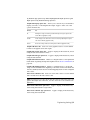
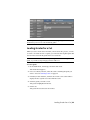
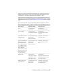
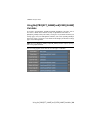
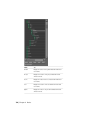
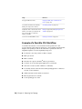
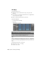
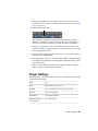
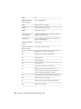
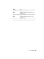
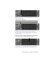
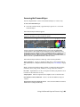
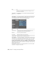
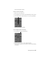
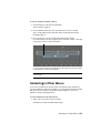
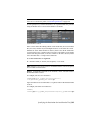
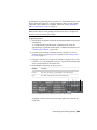
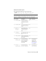
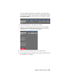
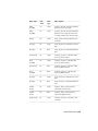
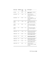
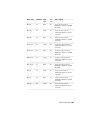
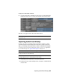
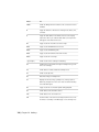
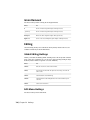
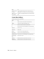
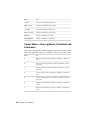
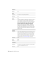
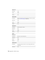
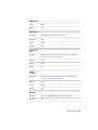
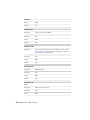
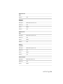
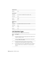
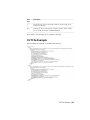
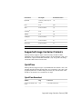
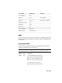
Video Type:
Pulldown: Link
Type:
Stereo:
Video Signal:
2Ki (25)
No
Dual
No
25 fps, 60 Hz, interlaced,
2048x1080, NDF timecode, RGB
4:4:4 data
2Kp (25)
No
Single
No
25 fps, 60 Hz, progressive,
2048x1080, NDF timecode, YUV
4:2:2 data
2Kp (25)
No
Dual
No
25 fps, 60 Hz, progressive,
2048x1080, NDF timecode, RGB
4:4:4 data
2Ki (29.97)
No
Single
No
29.97 fps, 60 Hz, interlaced,
2048x1080, NDF timecode, YUV
4:2:2 data
2Ki (29.97)
No
Dual
No
29.97 fps, 60 Hz, interlaced,
2048x1080, NDF timecode, RGB
4:4:4 data
2Kp (29.97)
No
Single
No
29.97 fps, 60 Hz, progressive,
2048x1080, NDF timecode, YUV
4:2:2 data
2Kp (29.97)
No
Dual
No
29.97 fps, 60 Hz, progressive,
2048x1080, NDF timecode, RGB
4:4:4 data
2Ki (30)
No
Single
No
30 fps, 60 Hz, interlaced,
2048x1080, NDF timecode, YUV
4:2:2 data
2Ki (30)
No
Dual
No
30 fps, 60 Hz, interlaced,
2048x1080, NDF timecode, RGB
4:4:4 data
2Kp (30)
No
Single
No
30 fps, 60 Hz, progressive,
2048x1080, NDF timecode, YUV
4:2:2 data
GFX SDI Rasters | 693
Video Type:
Pulldown: Link
Type:
Stereo:
Video Signal:
2Kp (30)
No
No
30 fps, 60 Hz, progressive,
2048x1080, NDF timecode, RGB
4:4:4 data
Dual
694 | Chapter 21 Video Capture and Video Playout
22
Audio
Topics in this chapter:
■
■
■
■
■
■
■
About Audio on page 695
Audio Workflow on page 696
Importing an Audio File on page 696
Capturing an Audio File on page 698
Playing Back Audio with the Timeline on page 700
Playback Using the LTC Chase Option on page 703
Playout of Audio and Video on page 704
About Audio
There are a few ways you can hear audio during a timeline playback:
■
You can import audio files to the system.
■
You can capture audio from a video tape recorder (VTR) or audio tape recorder
(ATR).
■
You can have an external device chase the audio timecode by using the
longitudinal timecode (LTC) chase option.
The audio signal is captured and played back from the DVS or AJA breakout box
(BOB). For information on connecting the external audio devices, refer to your
695
hardware guide. When you are capturing, playing back, or playing out audio
tracks, you can select up to 16 tracks (eight tracks of DVS/AJA AES audio, or
16 tracks of embedded AJA audio) from the track selector at a sampling rate
of 48 kHz (16-bit or 24-bit). See Capture Menu Options on page 635 or Playout
Menu Options on page 655.
NOTE To monitor the audio from the DVS/AJA BOB, the AES audio needs to be
converted to an analog audio signal. To do this, use a digital audio mixer or a
digital to analog converter (e.g., the Lucid converter). Refer to your hardware
guide for information about the Lucid converter.
Audio Workflow
Use the following typical workflow to add audio to your video playback.
Step:
Refer to:
1. Import or capture the audio file.
Importing an Audio File on page 696, Importing
Audio From Wiretap on page 697, or Capturing
an Audio File on page 698.
2. Playback the selected audio
file/tracks with the video.
Playing Back Audio with the Timeline on page
700 or Playback Using the LTC Chase Option
on page 703.
3. Playing out the audio file/tracks with
the video.
Playout of Audio and Video on page 704.
Importing an Audio File
Lustre can use the audio files that you import into the scene's sacc_data\audio
directory.
NOTE The audio folder is automatically created when you create a scene.
The imported audio file can comprise of a single track or up to 16 interleaved
tracks.
There are two ways to import audio into Lustre:
■
Copying an audio file into the audio folder.
■
Importing audio through the Wiretap server.
696 | Chapter 22 Audio
To import an audio WAV or AIFF file:
➤
Copy the audio WAV or AIFF file into the scene's sacc_data\audio folder.
If using the Linux version of Lustre, the filename uses forward slashes.
The audio now appears in the Audio menu audio file list.
NOTE If you imported the audio file after launching Lustre, press Ctrl+R to refresh
the audio file list.
Importing Audio From Wiretap
You have the option of including audio tracks when you import content
containing audio from the Wiretap server. Since the content contains raw
audio, you can import the audio tracks as a WAV or AIFF file (the bit depth
of the file is preserved and the Single File Capture option is not applicable).
To set audio file type, see Capture Menu Options on page 635.
NOTE You cannot import audio tracks through Wiretap from a non-EDL file.
To import audio files using Wiretap:
NOTE All audio soft effects and dissolves must be rendered on a Visual Effects and
Finishing application prior to being imported into Lustre.
1 Click Editing in the Main menu, and then click Browse.
2 In the file browser, use the Wiretap server to navigate to a media file that
contains audio.
Importing Audio From Wiretap | 697
3 Make sure Include Audio is enabled, then select the file and drag it to the
Storyboard.
4 Click Setup in the Main menu, and then click Audio.
The audio file from the Wiretap media has been imported and is
automatically loaded and ready to play. If multiple tracks were imported,
the tracks are grouped together under the same file name. For example,
if the name of the media is 8TK_MUSIC, Lustre displays the file as
8TK_MUSIC_A[1-8].wav (where [1-8] represents the number of tracks
within the file).
NOTE You can only import audio tracks from Wiretap. The audio tracks cannot
be rendered back.
Capturing an Audio File
You can capture an audio signal of up to 16 tracks as a single 48 kHz (16-bit
or 24-bit), interleaved WAV or AIFF file. The audio is saved in the scene's
sacc_data\audio folder. If using the Linux version of Lustre, the filename uses
forward slashes.
NOTE The audio folder is automatically created when you create a scene.
To capture an audio WAV or AIFF file:
1 Click Editing in the main menu, and then click Capture.
698 | Chapter 22 Audio
2 Select the appropriate raster. See Selecting a Raster for Capture on page
642.
3 Select the audio file type, bit depth, and determine if you want to capture
the audio tracks as a single or multiple files. Single File Capture is enabled
by default.
4 Enable the audio track(s) you want to capture.
NOTE You have the option of capturing the video along with the audio. See
Capturing from Timecode on page 645.
5 Click the TC button to start the capture.
If the audio you are capturing is on numerous tracks and the Single File Capture
option is enabled, Lustre groups all the tracks with the same name and displays
them as a single file (e.g., file_name.wav). If Single File Capture is disabled,
each track is saved separately but grouped together in the audio file list. For
example, the audio file name will be file_name_A[#-#].wav, where the numbers
within the brackets represent the number of tracks within the file.
NOTE When you capture a broken selection (e.g., tracks A1, A3, and A5) and
Single File Capture is enabled, the resulting single audio file contains three tracks.
Therefore, in the Playout menu, tracks A1, A2, and A3 are enabled. If Single File
Capture is disabled, the three tracks are saved as three separate files and in the
Playout menu, tracks A1, A3, and A5 are enabled.
Capturing an Audio File | 699
Playing Back Audio with the Timeline
Once the audio file is in the audio folder, you can play it back at the same
time as your timeline.
To play back an imported audio file with the timeline:
1 Click Setup in the main menu, and then click Audio.
The Audio menu is displayed.
2 Select a file from the audio file list.
NOTE Only one audio file can be associated with the timeline.
3 Click Load Audio File.
The selected audio file is displayed in the Audio File field and the Play
Audio File button is automatically enabled.
NOTE When you capture an audio file, it is automatically loaded.
4 Select a Monitoring option. See Audio Monitoring Options on page 701.
5 (Optional) Set an audio offset if the audio is to begin at a certain time
before, or after, the video has begun. See Offsetting the Audio File on
page 702.
6 (Optional) Select a Sync option. See Sync Options on page 702.
Now when you play the timeline, the audio file is played as well.
NOTE Disable the Play Audio File button if you do not want to hear the audio
during playback.
700 | Chapter 22 Audio
While the audio file is playing back, you can scrub the audio.
Press:
To:
Alt+click location in the shot/scene
timebar
Scrub the audio to the location you selected.
Ctrl+Alt+drag in the shot/scene
timebar
Scrub the audio forward or backward quickly.
Audio Monitoring Options
When you are playing back audio with your video, you need to make sure
your playback settings correspond to your audio configuration. Typically,
each track is played through a corresponding port (e.g., track 1 passes through
port 1, track 2 passes through port 2, etc.), but your system might be configured
to have multiple tracks going through a single port (e.g., tracks 1, 3, and 5
pass through port 1). The Monitoring option allows you to set how the tracks
are played back.
NOTE If you disable any audio tracks in the Playout menu, it will not be heard
during playback.
To select a monitoring option, click the Monitoring option box to select the
monitoring option you want.
Select:
Audio Device:
When:
Stereo Downmix
DVS or AJA
There are only two audio tracks that are supported
on the audio monitoring device. All the odd
numbered tracks (e.g., 1, 3, 5, etc.) go through
port 1 and all the even numbered tracks go
through port 2.
4-Track
Downmix
DVS or AJA
There are only four audio tracks that are supported
on the audio monitoring device.
8 Tracks
DVS only
There are up to eight tracks and each track is supported on the audio monitoring device.
Audio Monitoring Options | 701
Select:
Audio Device:
When:
8-Track
Downmix
AJA only
There are only eight tracks that are supported on
the audio monitoring device.
16 Tracks
AJA only
There are up to 16 tracks and each track is supported on the audio monitoring device.
NOTE The audio monitoring option can also be set within the Engineering settings
tab of the project configuration settings. See Engineering Settings on page 29.
Offsetting the Audio File
When you playback the audio with the timeline, both the audio and video
begin at the same time. If you want your audio to play before, or after, the
video has begun, you need to enter an offset for the audio file. Use the Audio
Slip option to offset the audio file. For example, if the audio file starts two
seconds after the start of the timeline, create a two second offset.
To offset the audio:
➤
Do one of the following:
■
Click and drag the Audio Slip sliders to offset the audio. If the audio
starts before the video, drag right to set a positive offset. If the audio
starts after the video, drag left to set a negative offset. You can use
one or both sliders to set the duration of the offset.
■
Right-click within the slider to display the calculator and enter the
frames and/or seconds offset to align your audio and video.
Sync Options
Depending upon the output device you are using to view the timeline, the
audio and video might not be in sync. Use the Sync Options feature to sync
the audio and video. When you enable a sync option, a pre-calculated default
is already applied. You only need to enter a value if the audio and video are
still not in sync.
702 | Chapter 22 Audio
DVI
Syncs the audio to the video that is displayed on the monitor (DVI).
GFX SDI Syncs the audio to the video that is displayed on an external device
(e.g., projector, broadcast monitor, etc.).
SDI Syncs the audio to the video that is displayed on an external device
connected to the DVS/AJA BOB.
To sync the audio and video:
1 In the Audio menu enable the Sync Options button corresponding to
your output viewing device.
NOTE Your system can be connected to multiple viewing outputs, but the
sync is only applied to the option that is enabled.
2 (Optional) Click within the field and drag the mouse left or right to set
the frame value for the sync. Enter a negative number if the audio plays
after the video has begun and enter a positive number if the audio plays
before the video has begun.
Playback Using the LTC Chase Option
The LTC Chase Option allows you send the timeline's timecode through the
DVS BOB to an audio device that can chase the LTC timecode. By default, the
LTC timecode is the same as the record time (REC TC). For example, if the
start timecode for the timeline is 10:00:00:00, the LTC will be 10:00:00:00.
When you move the shot positioner to a further position in the timeline and
press play, the LTC value is also updated so it is in sync with the record
timecode.
NOTE Your LTC Chase Option settings are saved in the context.config file.
To play back the audio track using the LTC Chase Option:
1 Click Editing in the main menu, and then click Capture.
Playback Using the LTC Chase Option | 703
2 Select the appropriate raster to observe the audio and video files together.
See Selecting a Raster for Playout on page 661.
3 Make sure the audio device is set to chase.
Now when you play back the timeline, the audio track is played at the
same time.
Use Explicit Timecode
If the audio device has a different timecode than the timeline, you can set a
different timecode by enabling the Use Explicit TC button. For example, if
your source timecode starts at 10:00:00:00 and your audio timecode begins
at 11:00:00:00, you can enable the Use Explicit TC option and create an offset
of 1:00:00:00.
To play back an audio track with a different timecode:
1 Click Editing in the main menu, and then click Capture.
2 Select the appropriate raster. See Selecting a Raster for Playout on page
661.
3 Click Setup in the main menu, and then Audio to display the Audio
menu.
4 Enable Use Explicit TC.
5 In the timecode field, enter the timecode of when you want the audio
track to begin.
Now when you move the shot positioner, the audio and video are in
sync.
Playout of Audio and Video
Once you have verified the playback of your audio file/track(s) and timeline,
you can play out the timeline to tape. See Playing Out to a VTR on page 660.
704 | Chapter 22 Audio
Working with Wiretap
23
Topics in this chapter:
■
■
■
■
■
■
■
■
■
■
■
■
About Lustre and Wiretap on page 705
Before You Begin on page 706
Supported Filesystems and Media Types on page 709
Sample Workflows on page 712
Preparing the Wiretap Timeline for Lustre on page 714
Configuring Wiretap and Lustre on page 715
Setting Up the Lustre Wiretap Project on page 720
Browsing for Remote Footage on page 722
Importing the Wiretap Timeline on page 726
Working with Soft-Imported Media on page 727
Rendering Shots on page 729
Troubleshooting on page 735
About Lustre and Wiretap
Wiretap is Autodesk's cross-platform client-server interoperability framework,
providing Lustre with high-performance access to remote media and metadata.
With Wiretap, there is no need to export files from the Autodesk Visual Effects
and Finishing application, nor to output to a VTR, prior to grading in Lustre.
You can import Visual Effects and Finishing timelines directly from the host
application, and read/write clips and frames on remote Visual Effects and
705
Finishing Stone FS and Standard FS storage devices with the same ease as you
would local media.
Lustre gains access to the remote media and metadata via Wiretap servers
running on the host workstations. A Wiretap server is installed by default with
most Visual Effects and Finishing applications, and runs independently of the
application. By default, Lustre automatically detects all the Wiretap servers
running on the Wiretap network. You can then browse for footage on the
remote filesystem and load it into the Shot bin or timeline, just as if it were
locally attached storage.
Lustre can interpret a Visual Effects and Finishing timeline as a single
one-sequence clip, or as an imported timeline. When you reference a Wiretap
timeline in Lustre, the dissolve and splice transitions are maintained. The
Wiretap timeline appears on the Lustre Storyboard as a series of shots and
transitions. Each shot comprising the timeline is added separately to the Shot
bin. Working with remote timelines containing soft-imported clips is equally
possible.
Lustre can import a multi-layer timeline from a Visual Effects and Finishing
application and export it to the Wiretap server (only available with Wiretap
2010 Extension 1 or higher). When gaps are imported from a multi-layer
timeline, they are seen as black media for Layer 1 and appear transparent for
the layers above Layer 1.
Regarding clip playback speed, network bandwidth and traffic play the expected
role. On an optimized GigE network, for example, you can achieve up to 80
MB/sec throughput. This is enough for real-time playback of SD clips, or about
1/4 real-time for 2K material. Better results can be achieved using InfiniBand.
Note that the Visual Effects and Finishing application on the Wiretap server
host workstation can also affect performance. Visual Effects and Finishing
applications have guaranteed access to the 'local' framestores—remote access
by Lustre over Wiretap is at a lower priority. If you notice playback is suffering,
consider rendering local proxies for the remote material.
Once you are finished grading the material from the Stone FS or Standard FS,
there are different rendering possibilities. As with any Lustre grading project,
you can render to the local storage array. Under Wiretap it is also possible to
render back to the Stone FS or Standard FS, and to publish soft-import links
to rendered media.
Before You Begin
This section presents important points to consider before beginning to work
with Wiretap.
706 | Chapter 23 Working with Wiretap
Timeline Considerations and Restrictions
When creating a Visual Effects and Finishing timeline for use in Lustre, please
note the following.
■
Drop Frame and Non-Drop Frame: Lustre now supports a timeline with a
mix of media that has drop frame and non-drop frame. Instead of using
only the timeline frame code mode, it now also uses the source clips’ frame
code mode.
■
Soft Effects: All soft effects and transitions must be processed prior to
importing the timeline into Lustre.
■
Supported Timeline Elements: Colour sources, timeline gaps, dissolve
transitions, and fade-ins and fade-outs are supported in Lustre.
■
Dissolves: These are regenerated in Lustre, but only with linear animation.
If a dissolve from a Visual Effects and Finishing application has a different
type of curve, or keyframes, this data will not be read in Lustre. Previously,
when you imported a timeline with dissolves from a Wiretap server, the
dissolves were all shown as centre dissolves within Lustre. Now when a
timeline is imported into Lustre, the dissolves are shown accordingly (i.e.,
from cut, centre, up to cut, or custom). This is only supported by Wiretap
server 2010 and higher.
■
Unsupported Transition Types: Wipe and Axis transitions are unsupported.
These are presented as single shots in Lustre.
■
Focus Point and Saving: In a Visual Effects and Finishing application
timeline, the positioner's focus point indicates the layer of interest for edits
and other operations. It also determines what appears when you import
the timeline into Lustre. When saving the timeline for use in Lustre, ensure
the focus point is on the top-most layer you want included in the Lustre
timeline. For example, if the Visual Effects and Finishing timeline contains
four layers and the focus point is on the third layer when it is saved, only
three layers are included in the Lustre timeline.
Wiretap Limitations
It is important to note the following limitations:
■
Dust Removal: Media located on the Stone FS or Standard FS cannot be
used for dust removal. You need to publish (from a Visual Effects and
Timeline Considerations and Restrictions | 707
Finishing application) the content to a shared location before performing
any dust removal.
■
Marry Grade Files: Media located on the Stone FS or Standard FS cannot
be used to create Marry Grade files. You need to publish (from a Visual
Effects and Finishing application) the content to a shared location before
creating the Marry Grade file.
■
Fade-Ins: Avoid having a timeline starting with a fade-in at record timecode
00:00:00:00.
■
Tape Names: Avoid using different shots that have the same timecode and
tape name.
■
Hard-Committing: Hard-committing a selection of shots creates a new clip
with a tape name of COMMIT, and a source timecode obtained from the
record timecode. There is no need to add this information to the shot
manually. Hard-committing a single shot preserves the original tape name
and timecode.
■
Start Timecode: The Start timecode of the timeline should not be negative.
Also, avoid using a timeline that begins with a fade-in and has a start
timecode of 00:00:00:00.
■
Saving to a Clip Library: Once you have added a clip to a clip library, make
sure to switch to a different clip library. This both saves the clip library,
and allows Wiretap to broadcast the updated information about the
timeline and clips.
■
Dual Library View: In Visual Effects and Finishing applications, the Dual
Library View mode displays the contents of two clip libraries
simultaneously, each in its own panel. When you switch from Dual Library
View back to Single View, the newly-hidden library remains selected by
the application, and is read-only to Wiretap. Lustre will be unable to render
media to the clip library until it is deselected.
Wiretap Compatibility
You can view and write back to projects created in any current Visual Effects
and Finishing application. However, if a project was created using an earlier
version of the software, Lustre has read-only access to it. Similar considerations
apply to the Wiretap server. That is, Lustre has read/write access to media via
any current Wiretap server. Earlier Wiretap servers may provide read-only
access. The version of the Wiretap server is shown in the Lustre browser.
708 | Chapter 23 Working with Wiretap
Networking
Lustre and Visual Effects and Finishing applications communicate through
Wiretap over a network connection. The network infrastructure can be GigE
or InfiniBand. A GigE connection is sufficient for SD and HD 8-bit workflows.
An InfiniBand connection is recommended for high-resolution projects like
HD 10-bit, 2K, and beyond.
See Configuring Wiretap and Lustre on page 715 and the Autodesk Stone and
Wire Filesystem and Networking Guide.
Supported Filesystems and Media Types
From the perspective of the Lustre user, there are no operational differences
between accessing media on a Stone FS and a Standard FS for colour grading.
However, there may be differences in performance. Performance varies when
using Standard FS, depending on the configuration. Refer to “Standard FS
Performance Expectations” in the Autodesk Stone and Wire Filesystem and
Networking Guide.
Supported Image File Types
Lustre can access the following uncompressed image files from a Stone FS or
Standard FS:
■
8-bit RGB
■
10-bit RGB
■
16-bit RGB (for 12-bit uncompressed or 16-bit soft-imported clips)
■
Soft-imported clips in their original format (DPX, TIFF, SGI, and TGA)
Although Autodesk's Visual Effects and Finishing products support the 16-bit
RGB compressed format, Lustre does not. If directories containing this format
are browsed, no media will appear.
Soft-Imported Media
In a Visual Effects and Finishing application, soft-importing creates a clip that
references unmanaged media. Unmanaged media typically resides on shared
network storage, such as a SAN or NAS, where numerous applications can
Networking | 709
have equal access to it, avoiding data duplication. If soft-imported media is
overwritten, the clip referencing it is updated accordingly. If soft-imported
media is deleted, the clip referencing it displays a checkerboard pattern
indicating that the media files can't be found. Inversely if, in the Effects or
Finishing application, all clips referencing media are deleted, the source media
remains unaffected. Basically, soft-imported media is unmanaged, whereas
imported media is managed.
Published Media
Publishing consists of exposing managed or unmanaged media to a location
accessible by other applications. Once published, the media is still being
referenced in a clip library, just like any other clip, but automatically becomes
soft-imported and unmanaged media. If the publish destination resides on
the same volume and if the format of the published files is the same as the
original file format, hard links to the managed media can be created as an
option. This media is accessible to Lustre and unmanaged by the Effects and
Finishing application.
If you are accessing media residing on a direct attached storage over a slow
network connection via Wiretap, you may choose to publish your media to
a shared network storage, which allows Lustre to access the media through a
fast network storage connection. See Sample Workflows on page 712.
Soft-Import Streaming Media Support
With Wiretap, Lustre can read compressed media file types that are otherwise
not natively supported. For example, users can access soft-imported formats,
such as Quicktime®, over the network because the Wiretap Server converts
the media on-the-fly without Lustre having to decode the files.
Lustre supports compressed media through Wiretap. The following compressed
file formats are converted on-the-fly by the Wiretap Server:
■
Quicktime (no extension)
■
Quicktime (.MOV/.mov)
■
Media Exchange Format (.MXF/.mxf)
■
Alias® (.als)
■
Jpeg (.jpeg)
710 | Chapter 23 Working with Wiretap
■
Tdi/Maya® (.iff)
■
Macintosh®Pict (.pict)
■
Pixar (.picio)
■
Softimage® (.pic)
■
Wavefront® (.rla)
NOTE It is also possible to work with compressed media outside of a Wiretap
workflow. See Compressed Media Support on page 177.
For a list of Lustre-supported native file formats, see Accessing the File Browser
on page 165.
Mixed Media Support
A 'mixed' clip or timeline contains media of different storage formats. Typically,
this kind of timeline contains both media from a Stone FS framestore and
media soft-imported from a Standard FS framestore. In earlier versions, these
clips could not easily be used by Wiretap clients without an explicit stonifize
or publish from within the Visual Effects and Finishing application. As a result
of server-side video media conversion, this is no longer necessary.
NOTE One limitation is that the frames within a given shot must be the same
format throughout the shot. For example, a shot must have all Stone FS media or
all .DPX media.
Proxy Media
A Lustre user can see proxy media on a Wiretap server by enabling the Half
resolution button in the player. It is also possible to generate local proxies for
Wiretap content. See Project Menu Settings on page 720 and Viewing Local
Proxies for Wiretap Media on page 721. Lustre can create proxies as you are
rendering the hires content to the Wiretap server by enabling the Proxy
Rendering button within Network Rendering of the user configuration settings.
See Network Rendering Menu Settings on page 721.
Mixed Media Support | 711
Sample Workflows
The ability to access remote footage makes it possible for Lustre to share footage
with other Autodesk products. The example workflows provided below offer
high-level descriptions of how Lustre could be integrated into different
post-production pipelines.
NOTE While Smoke is used in the examples, other applications such as Flame are
equally applicable.
Workflow #1: Importing One-Sequence Clips
In the one-sequence workflow, you work with a single clip representing the
timeline coming from Wiretap. In this case, files are first imported into Smoke
from the Stone FS and assembled into a timeline created especially for Lustre.
The timeline does not contain any splices or soft transitions. Lustre then
accesses the timeline as a one-sequence clip by way of Wiretap. This workflow
is particularly useful as a guide for a confidence check or scene detection.
NOTE A one-sequence clip appears as a single shot on the Lustre timeline and in
the Shot bin. You can perform a scene detection on the clip in order to break it
down to its component shots. See Using Scene Detection on page 271.
In Lustre, you create local proxies, grade them, and then render the source
clips back to the Stone FS using any of the standard Render mode controls in
the Render Local menu. See Specifying the Destination for Local Render Files
on page 594. The graded material is imported into Smoke to create an updated
timeline to which finishing touches are applied prior to rendering the final
clip.
Workflow #2: Importing Timeline
Importing a Timeline allows you to work with an editorial sequence that
contains shots and soft transitions (such as dissolves). In this case, timelines
are created in a Visual Effects and Finishing application and Lustre gains access
to the timeline by way of Wiretap. This is a useful workflow for shot-to-shot
grading.
NOTE The timeline includes information for all the segments in a clip, including
the head and tail information for dissolve and splice events. When you load a
Timeline clip, it auto-assembles, allowing you to bypass the conform step.
712 | Chapter 23 Working with Wiretap
Lustre renders the final clip to local storage using one of the four rendering
options in the Render Local menu. See Specifying the Destination for Local
Render Files on page 594.
Workflow #3: Smoke Renders Final Version
Smoke and Lustre users each access the same files from the external SAN or
NAS, and work on them simultaneously. The Smoke user assembles the files
and creates a multi-layer timeline while grading is performed on the
one-sequence clip in Lustre. At any time during the process, Smoke can be
made to publish metadata to reflect editorial changes. Lustre can then be used
to re-conform and create a new version of the timeline based on updates
performed in Smoke. When grading is complete, the source clips are rendered
by Lustre to the external storage using any of the standard Render Place
controls in the Render Local menu. See Specifying the Destination for Local
Render Files on page 594. The timeline can then be updated in Smoke by
soft-importing the graded sources. Finishing touches are applied to the timeline
in Smoke prior to rendering the final clip.
NOTE As an alternative to rendering to the SAN or NAS, Lustre could render to
the Stone FS in order to allow Smoke users to bypass the soft-import step.
Workflow #4: Lustre Renders Final Version
As in the previous example, files are soft-imported into Smoke and Lustre in
order to be worked on at the same time. The only differences are: instead of
referencing the timeline as a one-sequence clip, it is referenced as an timeline;
Lustre renders the final version of the timeline, instead of Smoke.
Workflow #5: Simple Source Grading
The following procedure illustrates a possible workflow for source grading for
complex projects that include multi-layer timelines with numerous effects,
transitions, etc. Since Wiretap flattens the timelines it imports from a Visual
Effects and Finishing application, for complex projects, it is worthwhile creating
a new single-layer timeline in the Visual Effects and Finishing application. In
this way, all the material needed by the Effects and Finishing artists can be
made available.
Workflow #3: Smoke Renders Final Version | 713
Workflow for simple source grading
1 In Smoke, capture and import media from the off-line editor as a timeline.
For greatest flexibility in the colour grading process, capture the material
in A-mode or C-mode—that is, in ascending timecode sequence.
2 Create a timeline in Smoke that is especially for grading in Lustre,
containing all the clips in a single video layer.
This can be accomplished most easily by selecting all the source clips
needed in the clip library reel and performing a Load and Join operation.
3 In Lustre, use Wiretap to import the timeline created in the above steps.
4 Grade the sources in the imported timeline, then render it back, via
Wiretap.
The rendered clips contain the updated grading but the same tape name
and timecode information as the original clips.
5 In Smoke, create a copy of the multi-layer timeline—that is, the destination
timeline.
6 Save the unlinked timeline to the clip library where Lustre has rendered
the media, and relink.
The multi-layer timeline now contains the graded clips.
Preparing the Wiretap Timeline for Lustre
Before you can read a Visual Effects and Finishing timeline using Wiretap, the
Visual Effects and Finishing artist must prepare the timeline.
To save a Wiretap timeline to a Visual Effects and Finishing clip library:
1 Process soft effects and transitions (see your Visual Effects and Finishing
application's User Guide).
2 Save the timeline to the Clip Library.
NOTE When saving a timeline to the Clip Library for use in Lustre, the position
of the focus point is important. See Timeline Considerations and Restrictions
on page 707.
3 Exit the library by changing to a different clip library.
714 | Chapter 23 Working with Wiretap
Exiting the library updates the information in the Visual Effects and
Finishing database, making it available to Wiretap, and frees up the
directory for read/write activity in Lustre.
Configuring Wiretap and Lustre
Before you begin using Wiretap with Lustre, some one-time configuration is
required. Depending on how you will be using Wiretap, the following items
might require configuration:
■
Dual network support
■
Wiretap server auto-detection
■
Access to a shared storage mount point
■
Soft-imported timelines
Configuring Dual Network Support
If your facility has both a GigE network and an InfiniBand network, you can
configure Wiretap to use both. The Wiretap server will then make use of the
high-bandwidth network for moving media, greatly improving network
performance and increasing reliability. The behaviour is transparent to
end-users.
To configure the Wiretap server to use InfiniBand for media transfers:
1 On the workstation hosting the Wiretap server, open the Wiretap
configuration file, wiretapd.cfg, using a text editor.
The file is located in the following directory:
/usr/discreet/sw/cfg
2 Scroll down to the [Server] section.
This section lists the IP addresses of the network interfaces used by
Wiretap, in the order in which the connections are attempted.
3 In the case of a facility with both a GigE and an InfiniBand network, the
IP address of the InfiniBand network must be first in the list, at IP0.
In the following example, the InfiniBand network IP address is
10.10.11.213, and the GigE network IP address is 192.168.129.3:
Configuring Wiretap and Lustre | 715
[Server]
IP0=10.10.11.213
IP1=192.168.129.3
4 Make the appropriate entries for your own networks, then save and close
the file.
5 You must restart the Wiretap server for your changes to take effect:
/usr/discreet/sw/sw_restart
Configuring Lustre to Work with Wiretap
When starting Lustre, Visual Effects and Finishing systems running Wiretap
servers on the same network are detected and displayed in the Browser by
default. The Wiretap Server can be identified by its host name or IP address,
depending on how the workstation's network settings have been configured.
You can edit the init.config file to configure Lustre to restrict what is displayed
to a specified selection of Wiretap servers if you want to limit access.
The Configuration File
All Wiretap-related items are located in the init.config file, located in the
following directories:
■
C:\Program Files\Autodesk\Lustre2010 (Windows)
■
/usr/autodesk/lustre2010 (Linux)
To display a specified selection of Wiretap servers:
1 Open the init.config file in a text editor.
2 In the <Wiretap> section, change the Wiretap server auto-detection
state to 'Off'.
<ServerAuto state=”Off”>
NOTE Settings in the init.config file are case-sensitive. You must use a capital
'O' when setting the auto-detection state to Off.
3 In the <WiretapServerGroup> subsection of the <Wiretap> section,
add each Wiretap server's IP address or host ID to a separate
<WiretapServer String> line.
716 | Chapter 23 Working with Wiretap
NOTE The Wiretap server string lines must be inside the open and close
comment tags of the <WiretapServerGroup> example.
For example, if your network uses DNS:
<WiretapServer string=”berlin”/>
Otherwise:
<WiretapServer string=”192.168.0.1”/>
You can add as many workstations as you need in this list. Just add one
WiretapServer line for each workstation.
4 Save the init.config file and start Lustre.
Configuring the Wiretap Server to use a Shared
Storage Mount Point
By default, Wiretap enables access to Visual Effects and Finishing media by
way of the Wiretap server. However, if the applications share a storage mount
point, Lustre can gain access to the media directly, while reading the metadata
off the Wiretap server. You configure this behaviour by adding entries to the
Wiretap path translation file.
Recall that the Linux and Windows operating systems present file path names
using different syntaxes. For example, the path to network storage on a SAN
that appears to a Windows workstation as F:\SAN might appear on Linux as
/SAN. The path translation file ensures the path names are translated correctly
as information moves between each application.
There are two main steps. First, determine how the shared mount point is
seen by each system. Next, create a new translation rule-pair for each mount
point in the Wiretap path translation file. In this way, you ensure that the
Standard FS media used by a Visual Effects and Finishing timeline is directly
read/write accessible in Lustre.
Note the following:
■
The mount point/mapped network drives must already be set up in their
respective operating systems before you refer to them in the path translation
file.
■
You can create translation rules on a host-by-host basis (most common),
or on a per-platform basis. In situations where several hosts see their mount
Configuring the Wiretap Server to use a Shared Storage Mount Point | 717
points in the same way, you can simplify the file by creating groups of
hosts.
■
Place each rule in the rule-pair on a separate line.
■
Wiretap applies the rules in the order in which they appear in the file.
For complete information, see the Autodesk Stone and Wire Filesystem and
Networking Guide.
To configure the Wiretap path translation file:
1 On the workstation hosting the Wiretap server, open the Wiretap path
translation configuration file, wiretap_path_translation_db.xml, using a
text editor.
The file is located in the following directory:
/usr/discreet/wiretap/cfg
2 Scroll down to the section of interest, for example, the Translation
between two operating systems section.
3 Copy and modify an existing entry, or enter your own rule-pair.
For example, the following rule-pair enables Lustre to read and write a
shared mount point seen by the Linux workstation as /SAN, and by the
Windows workstation as F:\SAN:
<map src_os="WindowsNT" src_path="F:\SAN"
dst_os="Linux" dst_path="/SAN" />
<map src_os="Linux " src_path="/SAN" dst_os="
WindowsNT "dst_path= "F:\SAN" />
4 Save the wiretap_path_translation_db.xml file and restart the Wiretap server:
/usr/discreet/sw/sw_restart
Restarting the server is not essential, since the Wiretap server regularly
polls the path translation file for changes. However, by restarting the
server, you force it to be parsed. This is a good way to test the file for any
XML syntax errors. Access to the mount points themselves is not tested
during this phase.
Configuring for Soft-Imported Timelines
If you will be working with timelines containing soft-imported media, there
are two configuration details to take care of. First, you must configure the
718 | Chapter 23 Working with Wiretap
Wiretap path translation table to permit the use of a shared storage mount
point (as indicated in Configuring the Wiretap Server to use a Shared Storage
Mount Point on page 717). Next, you must correctly set up the directory
structure on the shared storage mount point, as indicated in the following
procedure.
To configure projects to access soft-imported timelines over Wiretap:
1 On the shared network storage system, such as a SAN or NAS, ensure that
files to be soft-imported into the Visual Effects and Finishing application
are all located in the same directory structure.
For example, the directory on the shared network storage system could
be configured as follows:
/SAN/lustre/scans_full/2k/images/2048x1556/
Such a configuration is necessary in order for you to be able to render
locally with Lustre.
2 On the Visual Effects and Finishing workstation where the Wiretap server
is running, ensure the Wiretap path translation file contains entries to
translate the paths to the shared mount points from one operating system
to another.
This is necessary so that Lustre can have access to soft-imported media
in Wiretap timelines.
See Configuring the Wiretap Server to use a Shared Storage Mount Point
on page 717.
3 In the Lustre Project Management menu, ensure that the Scans Full Home
path points to the Windows drive configured in the Wiretap path
translation file (S:\), for example:
S:\lustre\scans_full\2k\images\2048x1556\
All other project setup fields can be configured as usual.
4 The shared network storage system, such as the SAN or NAS, must be
mounted and accessible (writeable) from both the Wiretap server host
and Lustre workstation.
You are now ready to import soft-imported timelines by way of Wiretap.
TIP You can tell whether or not the directory has been properly translated
by checking to see if the <Home> prefix appears as part of the shot
information in the Shot bin. See Viewing Media File Information on page 174.
Configuring for Soft-Imported Timelines | 719
Setting Up the Lustre Wiretap Project
Lustre projects that make use of Wiretap must be configured differently than
regular Lustre projects. The choices you make depend upon several factors.
These factors include whether you will render locally or to a SAN or NAS (as
can be the case in non-Wiretap setups), or use Wiretap to render to a Stone
FS or Standard FS. In addition, you need to decide whether you will generate
local proxies for the clips, or make use of proxies that might already exist on
the Stone FS or Standard FS. If your project will make use of soft-imported
media, additional considerations apply.
This section describes the settings for Lustre projects that make use of Wiretap,
for all configurations other than those that use soft-imported media. For
Wiretap projects that also make use of soft-imported media, see Working with
Soft-Imported Media on page 727. For general considerations on setting up
projects, see Project Management on page 11.
Project Menu Settings
The following table explains the criteria to consider for each of the fields in
the Project menu related to Wiretap projects.
Field
Criteria
Scans Full Home
■
To access a Stone FS or Standard FS, this field should have the
same path as Project Home.
■
To access 'published', unmanaged media (also called soft-imported media), populate this field with the path to the media
residing on the shared network storage (for example, a SAN or
NAS). For example, if the media is located in F:/SAN/Project/001,
the Scans Full Home path should be F:/SAN.
Scans Half Home
■
To use proxies coming from a Stone FS or Standard FS, this field
should have the same path as Project Home.
Renders Full
Home
■
To render media to a Stone FS or Standard FS, browse to a clip
library destination. This automatically sets the Wiretap render
path.
■
To render media to a shared network storage device (for example, a SAN or NAS), browse to a shared network destination.
See Rendering Shots on page 729.
720 | Chapter 23 Working with Wiretap
Field
Criteria
Renders Half
Home
■
To render proxy media to a Stone FS or Standard FS, browse to
a clip library destination. This automatically sets the Wiretap
render path.
■
To generate local proxies from media coming from a Stone FS
or Standard FS, populate this field with the path to your local
storage array.
■
To generate local proxies from Published content, populate this
field with the path to the local storage array or shared storage
network.
Rendering Menu Settings
If you are rendering to a Stone FS or Standard FS, enable the Same Format As
Scans button. If you plan to render to shared storage, select the file format to
be used (DPX, TIFF, etc.). Make sure the format you select is supported by the
Wiretap server. See Supported Image File Types on page 709.
Network Rendering Menu Settings
To improve interoperability of projects used by Lustre and a Visual Effects and
Finishing application, enable the Proxy Rendering button. Proxies are
automatically generated when you render the timeline. This makes it efficient
to load clips in a Visual Effects and Finishing application as you no longer
have to render proxies first.
Viewing Local Proxies for Wiretap Media
As with non-Wiretap Lustre projects, proxy generation reduces processing
time and can be helpful when working with large image formats. Wiretap
projects will make use of Visual Effects and Finishing proxies, if available.
This, nevertheless, involves transferring the proxies across the network. It can
be advantageous to generate local proxies, regardless of proxy availability on
the Visual Effects and Finishing side. Note that you can generate the local
proxies at 100% of the original resolution. This allows you to work with
high-resolution material on the local Lustre storage, avoiding network traffic
without sacrificing image quality.
Rendering Menu Settings | 721
To view local proxies generated from the Wiretap media, enable the Local
Proxy button in the Network Rendering menu (see Network Rendering Settings
on page 34). When this button is disabled, you will be able to see the original
Visual Effects and Finishing Wiretap proxies using the network connection,
upon import. Note that this will not work for clips already imported when
the button was disabled.
Browsing for Remote Footage
Wiretap servers are displayed in the Lustre file browser as an IP address or
server workstation name, followed by the Wiretap server version. When you
manually open the Wiretap server entry in the browser, both Stone FS and
Standard FS filesystems are visible.
b
c
(a) Wiretap server workstation name (b) Stone FS volume (c) Standard FS volume
For details on using the file browser, see Accessing the File Browser on page
165.
NOTE If you are unable to browse the remote filesystem, ensure the Wiretap
service is functioning. See Verifying Connectivity between Lustre and the Wiretap
Server on page 735.
Viewing the Volume Hierarchy
Expanding a Wiretap volume presents its contents as a hierarchy.
722 | Chapter 23 Working with Wiretap
a
b
c
d
(a) Wiretap server (b) Free space on the file system (c) Read-Only indicator (d) Total
space on the file system
The following information is presented:
■
Wiretap server
■
Volume
■
Project
■
Library
■
Reel (optional)
■
Clip (in libraries and reels)
Note the following additional points:
■
When you access a Wiretap server's volume in the file browser, the
remaining space and the total space of the file server on the storage device
is also displayed.
■
Read-Only indicates the library is locked and new clips cannot be written
to it. This is the case when a Visual Effects and Finishing artist is browsing
the library, for example.
■
In the browser, click Refresh to refresh the view of your filesystem.
Viewing Volume and Clip Details
Expanding the volume presents additional details.
Viewing Volume and Clip Details | 723
a
b
c
d
e
(a) Wiretap server (b) Volume (c) Project (d) Library (e) Clip and Clip Metadata
A detailed view of a Wiretap clip is represented in the Shot bin and in the file
browser with the following information:
■
Clip name
■
Shot location
■
Frame range and timecode start/end
■
Full and proxy resolutions
■
Media type
For more information about viewing clip metadata, see Viewing Media File
Information on page 174.
One-Sequence and Timeline Views
By default, the Timelines Only button in the Browser is enabled, which allows
Wiretap content to be presented in a timeline form. You can also choose to
display the one-sequence representation of the Wiretap timeline by disabling
the Timelines Only button, in which case both the one-sequence and timeline
versions are displayed at the same time.
724 | Chapter 23 Working with Wiretap
b
a
(a) Timeline version (b) One-sequence version
The difference between the two is as follows:
■
One-sequence: a sequence of files is presented to Lustre with clip metadata
as opposed to timeline metadata and you can still see transitions as
'read-only'. This is useful, for example, when manually comparing the
contents of the timeline against a digital cut captured directly from an
offline video tape. See Performing a Confidence Check on page 269.
■
Timeline: a sequence of shots that contains source clip metadata (for
example, shot name, source timecode), dissolve, and cut transitions. This
allows you to recreate the timeline that you had in your Visual Effects and
Finishing application (in a single-layer format) when you import the
Wiretap timeline. You can then grade each shot and render back either a
single-sequence clip or render with the timeline structure intact.
Additionally, you can choose to display the clip thumbnails with or without
details about the clips by enabling Details for a detailed view or Proxies for
thumbnail-only view. For more information about the Browser, see Accessing
the File Browser on page 165.
One-Sequence and Timeline Views | 725
Importing the Wiretap Timeline
Please note the following points about importing footage from the browser:
■
To maintain the editorial structure and transitions of the Wiretap timeline,
it is recommended that you import the Wiretap timeline by dragging and
dropping from the browser directly to the empty Storyboard area.
■
If the Storyboard already contains a timeline, the new timeline is added
as a layer above the existing layer(s). It is added at its record timecode
position (not at the drop point), which contains the new timeline content.
■
If the Storyboard or timeline is empty, importing a timeline from Wiretap
automatically creates a cut. The name of the cut is the same as the name
of the timeline.
■
Source clips containing long tape names (more than seven characters) are
supported.
■
For long timelines, consider creating a new cut before dragging and
dropping a clip from Wiretap. See Creating a New Cut on page 56.
■
It is possible to load multiple timelines from Wiretap into different Lustre
timeline layers (this is only applicable if you are using a Wiretap server
version older than 2010 Extension 1). This is useful to create a timeline as
it appears in the Visual Effects and Finishing application. In this case, the
Visual Effects and Finishing artist must create multiple timelines, one for
each layer. In Lustre, you manually load these into the current timeline.
Lustre adds each layer based on the record timecode of the Wiretap
timeline.
■
Once the Wiretap timeline is regenerated as a Lustre timeline in the
Storyboard, the source clips are automatically added to the Shot bin.
■
If you drag and drop the Wiretap timeline directly into the Shot bin (as
you would for local footage), only the source clips are imported into the
Shot bin. The timeline is not created in Lustre.
■
By default, audio tracks are imported along with the timeline it is associated
with. If you do not wish to import any audio over Wiretap, disable the
Include Audio button. For more information about importing and playing
back audio from Wiretap, see Importing Audio From Wiretap on page 697.
■
Once shots are loaded into the Storyboard, information about the selected
shot is displayed in the Shot Info field.
726 | Chapter 23 Working with Wiretap
a
c
(a) Location of the Wiretap clip (b) Resolution of the clip (c) File format (d) Bit
depth per channel (RGB)
Working with Soft-Imported Media
This section presents the considerations that apply when working with
timelines or clips containing soft-imported media. When using soft-imported
media, be aware that you have no control if another user modifies the original
media files. All soft-imported clips that refer to the modified media files are
updated to reflect the change. Ensure that all users accessing the same media
are aware of these implications.
Creating Soft-Imported Links to Rendered
Media
You can create soft-imported clips from rendered material and write the
generated timeline back to the Wiretap Clip Library. The rendered results
reside in the destination specified in the project settings, and a soft-import
link is created on the Stone FS or Standard FS.
To create a soft-imported link to your graded renders in the Wiretap Clip
Library:
1 Click Setup, and then click Project to display the Project menu.
2 In the Renders Full Home field, enter the path for the graded files to be
rendered to.
For example, if your Windows drive is mapped to the network storage as
S:\, then the renders full home path should be S:/SAN/lustre_renders.
NOTE The shared storage network (i.e., SAN or NAS) must be mounted and
accessible from both the Wiretap Linux host and the Lustre workstation.
3 Click Render, and then click Local to display the Local menu.
Working with Soft-Imported Media | 727
4 Select one of the following render options:
■
Normal
■
No ShotID
■
One Sequence
■
Src Grade
5 Enter the path for the location of the soft-imported clip in the Render
Library field.
For example, 10.145.43.31@wt:/stonefs/project/library.
Note that you can set a default value for the Render Library field when
configuring the project, as described in the next procedure.
6 Enable the Wiretap Render button.
7 Click Start.
This renders the files to the specific path of the shared network storage,
and publishes the soft-import links to your rendered files in the
destination Wiretap clip library. A new scene grade reel containing the
soft-imported clips and/or timeline is created in the location specified by
the Render Library field.
To set the Render Library path as a project setting:
1 From the Main menu, click Setup, and then Settings. Select the project
to edit, and then click Edit in the Project group.
2 On the Network Rendering menu, enter the desired path in the Render
Library field in either of the following ways:
■
Navigate to the directory using the navigation aid button and browser.
728 | Chapter 23 Working with Wiretap
■
Enter the desired path directly in the Render Library field, in the
following format:
<Wiretap_server>@wt:/<volume>/<project_name>/<library>
For example:
rishikesh@wt:/stonefs/HD_project/lustresmoke
3 Save the settings for the project by clicking Save Project.
4 Click Exit Project.
5 To verify the path shows up as expected, from the Main menu, click
Render, and then Local.
The path appears in the Render Library field.
Rendering Shots
When you have finished grading the imagery from the filesystem, you can
render to the local storage array, or write back to the Stone FS via Wiretap.
NOTE Audio tracks that were imported through the Wiretap server cannot be
rendered back to Wiretap.
If working with soft-imported clips, you must also set up the directory structure
on the SAN or the NAS in such a way that Lustre can recognize it. See Setting
Up the Lustre Wiretap Project on page 720. You render clips from a local storage
the same way as you would for any other clip. See Rendering on page 587.
Rendering clips back to Wiretap requires that the render destination be
specified in the project setup. See Setting Up the Lustre Wiretap Project on
page 720. The render destination you specify in the project setup will determine
the location of the reel in which the rendered clip will be placed. See Rendering
with Wiretap on page 730.
NOTE The clip’s long tape name metadata is also rendered back through Wiretap.
You can use the Render menus to render your work. You can render selected
shots, all shots in a cut, a specific layer in the Timeline, or the flattened result
of a multi-layer timeline. To prepare for rendering, do the following.
Rendering workflow:
1 Specify the layer to be rendered.
Rendering Shots | 729
2 Set the resolution of the render files.
3 Set resize options, as needed.
4 Specify the destination for the render files.
5 Specify the output file format (if different than the original footage).
6 (Optional) Change the output colour space or specify an output LUT.
7 Set other options such as timecode burn-in and rendering with a viewing
LUT.
Rendering with Wiretap
When rendering with Wiretap, a new reel (based on the scene name, grade,
and timeline name) will be created in the destination Clip Library that was
defined when the project was created. See Project Management on page 11.
This is the syntax to use when rendering to Wiretap, or publishing soft-import
links to your graded sources:
<IP address or
hostname>@wt:/<volume>/<project_name>/<library>
In the above sample, <IP address or hostname> is the IP address or
host name of the Wiretap server. For a Stone FS, the volume is specified as
stonefs. For a Standard FS, it is specified as stonefs<#>—for example, stonefs2.
If, for example, 10.145.43.31@wt:/stonefs/HD_project/rendered_grades was entered
in the Renders Full Home field, the rendered clip will be placed in:
/stonefs/HD_project/rendered_grades/<scene>_<grade>_<timeline_name>
You can specify how you want render files to be organized in the Wiretap Clip
Library using the Render Place controls in the Render Local menu.
Normal Rendering Mode
A Normal render creates source clips (with or without head and tail frames)
and a timeline. The extension of the timeline is the grade that the timeline
is associated with (e.g., <cut/timeline_name>_grd<number>. In this
mode, dissolves are rendered, and cannot be further modified in the Visual
Effects and Finishing application.
For shots rendered to a Wiretap Clip Library, a new reel (based on the scene
name, grade, and timeline name) is generated in the Clip Library that was
730 | Chapter 23 Working with Wiretap
defined when the project was created. This is where the rendered material is
placed.
For example, if 10.145.43.31@wt:/stonefs/tutor/lustregrades was entered in the
Renders Full Home field, the graded rendered shots are placed in
10.145.43.31@wt:/stonefs/tutor/lustregrades. These shots contain the clip name,
grade name, and the shot's unique ID.
<clip_name>_<grade>_<unique_id>
(example:shot1_grd14_AB3E9770000053)
An additional clip with a _grd<number> suffix is also generated containing
the cut or timeline name. For example, if the grade name is grd14 from the
timeline called "interior_003", the additional file is:
interior_003_grd14
The graded timeline is generated based on the new rendered source files.
No ShotID Rendering Mode
As outlined in the Normal mode description above, when rendering clips to
Wiretap, a new reel (based on the scene name, grade, and timeline name) is
created in the Wiretap Clip Library and all rendered material is placed there.
The additional clip with the _grd<number> suffix is also generated.
One-Sequence Rendering Mode
As with Normal and No ShotID mode, when rendering clips to Wiretap, a new
reel (based on the scene name, grade, and timeline name) is created in the
Wiretap Clib Library and all rendered material is placed there.
One-Sequence mode generates one clip of the graded sequence containing
the Lustre cut or timeline name and the grade number. If, in Lustre, your
scene is named interior_003, the timeline is named FINAL_CUT, and the grade
file is named grd14, the new reel in the Wiretap Clip Library will be called:
/stonefs/HD_project/rendered_grades/interior_003_FINAL_CUT_grd14/
The rendered, one-sequence clip will contain the grade name:
FINAL_CUT_grd14
Source Grade Rendering Mode
Src Grade mode renders the complete timeline back to Wiretap with Lustre
grading applied, but dissolves and retimes are rendered as soft effects with
modifiable values. This is the most convenient rendering mode for regenerating
Rendering with Wiretap | 731
source clips for relinking in the Visual Effects and Finishing application, in a
“simple source grading” workflow.
For shots rendered to Wiretap, a new reel (based on the scene name, grade,
and timeline name) is generated in the library that was defined when the
project was created. This is where the rendered material is placed.
For example, if 10.145.43.31@wt:/stonefs/tutor/lustregrades was entered in the
Renders Full Home field, the graded rendered shots are placed in
10.145.43.31@wt:/stonefs/tutor/lustregrades/scene_grade. These shots contain the
clip name, grade name, and the shot's unique ID.
<clip_name>_<grade>_<unique_id>
(example:shot1_grd14_AB3E9770000053)
An additional clip with a _grd<number> suffix is also generated containing
the cut or timeline name. For example, if the grade name is grd14 from the
timeline called "interior_003", the additional file is:
interior_003_grd14
The graded timeline is generated based on the new rendered source files.
Rendered graded source files are renamed according to the grade number and
the clip's unique ID. For example: grd01_4323B1F4.
Rendering Wiretap Clips to Local or Network
Storage
The render directory structure for Wiretap clips is different from how local
scans are rendered to the local or networked storage. The location and structure
of the scene or grd directory depends on whether your shots are written on the
Stone FS, or soft-imported into the Stone FS, and is based on your project
directory structure. See Setting Up the Lustre Wiretap Project on page 720.
You can specify how you want render files to be organized under the grd or
scene directory using the Render Place controls in the Render Local menu.
These controls affect the location where they are saved and the naming scheme
of the render files.
NOTE There is currently no difference between Normal and No ShotID renders.
To set how render files are organized:
➤
Enable Normal, No ShotID, One Sequence, or Src Grade.
732 | Chapter 23 Working with Wiretap
NOTE Soloing and Muting rules for Wiretap rendering are the same as those for
local rendering. See Specifying the Destination for Local Render Files on page 594.
Normal Rendering Mode
Clips are rendered to sub-directories of a directory based on the scene name,
which Lustre creates automatically when you first render shots. From there,
they are rendered with each shot in its own grd_UID directory, creating the
final name by combining the grade name with the scene name.
For example:
Stone-based clips are rendered as:
<Home>/<scene>/grd/<grdXX_UID>/<resolution>/<scene_grdXX.xxxx>.dpx
Soft-imported clips are rendered to a directory called grd. With this grd
directory, all the shots are rendered to a single directory based on the source
location of the soft-imports (let's call it the source reel) and the grade name.
From there, the final name is created based on the source filename and Lustre
grade name.
For example:
Soft-imported clips are rendered as:
<HOME>/grd/<sourcereel_grdXX_UID>/<resolution>/<origfilename_grdXX_UID.xxxx>.dpx
If a source clip called shot13 has been soft-imported into the Effects or Finishing
application from this location:
/SAN/lustre/scans_full/2k/reel23/2046x1556/
Lustre then imports this soft-imported clip via Wiretap, saves the grade as
grd01, and renders it to the local or networked storage array. Lustre will take
the name of the shot directory preceding the resolution directory, in this case,
reel23.
For example:
Soft-imported clips are rendered as:
<HOME>/
grd/reel23_grd02_AB3E9770000053/2046x1556/shot13_grd01_4323B1F4.0001.dpx
No ShotID Rendering Mode
As with Normal renders, Stone-based clips are rendered to sub-directories based
on the scene name, which Lustre creates automatically when you first render
shots. From there, they are rendered with each shot in its own grd_UID
Rendering Wiretap Clips to Local or Network Storage | 733
directory, creating the final name by combining the grade name with the
scene name.
For example:
Stone-based clips are rendered as:
<HOME>/<scene>/grd/<grdXX_UID>/<resolution>/<scene_grdXX.xxxx>.dpx
As with Normal renders, soft-imported clips are rendered to a directory called
grd. With this grd directory, all the shots are rendered to a single directory
based on the source location of the soft-imports (let's call it the source reel)
and the grade name. From there, the final name is created based on the source
filename and Lustre grade name.
For example:
Soft-imported clips are rendered as:
<HOME>/
grd/<sourcereel_grdXX_UID>/<resolution>/<origfilename_grdXX_UID.xxxx>.dpx
One Sequence Rendering Mode
As with Normal and No ShotID renders, clips are rendered to sub-directories
of a directory based on the scene name, which Lustre creates automatically
when you first render shots. From there, under the sub-directory called grd,
the shots are rendered as a single sequence to a directory based on the grd
name. The filenames consist of the scene name, the grade name, and a
sequential number. There are no UIDs in the directory naming scheme.
Soft-imported clips are rendered to sub-directories based on the scene name,
which Lustre creates automatically when you first render shots. From there,
under the sub-directory called grd, the shots are rendered as a single sequence
to the sub-directory based on the grd name. The filenames consist of the scene
name, the grade name, and a sequential number. There are no UIDs in the
directory naming scheme.
For example:
Stone-based clips are rendered as:
<HOME>/<scene>/grd/<grdXX>/<resolution>/<scene_grdXX.xxxx>.dpx
Soft-imported clips are rendered as:
<HOME>/<scene>/grd/<grdXX>/<resolution>/<scene_grdXX.xxxx>.dpx
734 | Chapter 23 Working with Wiretap
Source Grade Rendering Mode
As with Normal and No ShotID renders, clips are rendered to sub-directories
based on the scene name, which Lustre creates automatically when you first
render shots. From there, they are rendered with each shot in its own grd_UID
directory, creating the final name by combining the grade name with the
scene name. In addition, Src Grade excludes dissolves and retimes and renders
the files with their pre-dissolve and pre-retime handles.
Stone-based clips are rendered as:
<HOME>/<scene>/grd/<grdXX_UID>/<resolution>/<scene_grdXX.xxxx>.dpx
As with Normal and No ShotID renders, soft-imported clips are rendered to a
directory called grd. With this grd directory, all the shots are rendered to a
single directory based on the source location of the soft-imports (let's call it
the source reel) and the grade name. From there, the final name is created
based on the source filename and Lustre grade name. In addition, Src Grade
excludes dissolves and retimes and renders the files with their pre-dissolve
and pre-retime handles.
Soft-imported clips are rendered as:
<HOME>/
grd/<sourcereel_grdXX_UID>/<resolution>/<origfilename_grdXX_UID.xxxx>.dpx
Troubleshooting
This section presents a few helpful procedures relating to the Wiretap server
and Lustre-server connectivity.
Verifying Connectivity between Lustre and the
Wiretap Server
Verify that you have proper connectivity over the network.
To verify connectivity (Windows):
1 On your Lustre workstation, click the Start button, and then click Run.
2 In the Run dialog box, type:
cmd
A command console is displayed.
Troubleshooting | 735
3 In the command console, type:
ping <IP address of Wiretap host or Wiretap host
workstation name>
Example system response
ping computer
Reply from 172.16.128.129: bytes=32 time=3ms TTL=63
A system response with ping times similar to the example, above, indicates
that your Lustre workstation can see the remote Wiretap host workstation.
To verify connectivity (Linux):
➤
On your Lustre workstation, open a shell and type:
ping <IP address of Wiretap host or Wiretap host
workstation name>
Example system response
ping computer
Reply from 172.16.128.129: bytes=32 time=3ms TTL=63
A system response with ping times similar to the example, above, indicates
that your Lustre workstation can see the remote Wiretap host workstation.
Starting and Stopping the Wiretap Server
The following utilities have been provided for starting, stopping, and restarting
the Wiretap server.
Utility
Description
sw_start
Starts the Wiretap server
736 | Chapter 23 Working with Wiretap
Utility
Description
sw_stop
Stops the server
sw_restart
Stops then restarts the server
The utilities are located in the following directory:
/usr/discreet/sw
Verifying that the Wiretap Server is Running
To verify a Wiretap server is running:
➤
On the Wiretap server, open a shell and type:
ps -ef |grep wiretap
Example system response
root 19579 10 May14 ? 00:00:00 /bin/sh /usr/discreet/sw/sw_wiretapd
root 19588 195790 May14 ?00:01:51 /usr/discreet/wiretap/<version_number>/ifffsWiretapServer -c /usr/discreet/wiretap/cfg/wiretapd.cfg
root27965 277280 10:02 pts/5 00:00:00 grep wiretap
In the above output, the
line/usr/discreet/wiretap/<version_number>/ifffsWiretapServer -c
/usr/discreet/wiretap/cfg/wiretapd.cfg indicates the version number of Wiretap
that is running. If you do not see information similar to this, restart the
Wiretap server.
Verifying that the Wiretap Server is Running | 737
738
24
Hotkeys
Topics in this chapter:
■
■
■
■
■
■
■
■
■
■
■
■
■
Storyboard Navigation on page 739
View Modes on page 741
Timeline Sort Modes on page 743
Notes on page 744
Calculators on page 744
Dust Removal on page 745
Grain Removal on page 746
Editing on page 746
Colour Grading on page 750
Numeric Keypad on page 756
Stereoscopy on page 761
Animation on page 761
Miscellaneous Functions on page 762
Storyboard Navigation
Use these hotkeys to navigate in the Storyboard and shot timebars.
Press:
To:
Up Arrow
Play forward.
739
Press:
To:
Down Arrow
Play backward.
Left Arrow
Go to the first frame of the previous shot.
Right Arrow
Go to the first frame of the next shot.
Spacebar
Toggle Play/Stop.
Shift+Spacebar
Switch to Render View mode, switch off the user interface, and
start playback.
Right Ctrl
Step one frame forward.
Right Alt
Step one frame backward.
Shift+I
Mark an in point for loop play on the Scene timebar.
Shift+O
Mark an out point for loop play on the Scene timebar.
Shift+L
Clear in and out points from the Scene timebar.
. (decimal point on
the numeric
keypad)
Toggle through play modes (loop sequence, loop shot, and loop
in and out points).
Tab
Toggle the Storyboard on/off. In the Editing menus, the Storyboard is always on.
Q
Switch between Storyboard viewing modes (regular and large
Storyboard view). Not applicable to the Editing menu.
. (period)
Update the shot's thumbnail according to the colour correction
applied on the current frame.
Shift+. (period)
Regenerates multiple Storyboard thumbnails consecutively,
starting from the current shot onwards.
Spacebar
Stop the multiple Storyboard thumbnail regenerating procedure.
Middle-drag
Pans the Storyboard.
F1
Go to Playhead A.
F2
Go to Playhead B.
740 | Chapter 24 Hotkeys
Press:
To:
F
Toggle between the collapsed Storyboard and the original.
View Modes
Use these hotkeys to switch between the different view modes.
Press:
To:
P
Switch to Render View mode.
Shift+P
Switch to Render View mode and have Lustre re-detect and reparse the rendered files. This is useful when the files are not found
automatically, for example, when they are not rendered from the
application itself, but using the command line render.
Shift+ Spacebar
Switch to Render View mode, switch off the user interface, and
start play. (This hotkey cannot be used in any of the Editing
menus.)
O
Switch to Result view (this is the default).
I
Switch to Primary view. In this mode, only primary correction
appears (secondaries or plugins are turned off).
Middle-drag
Pans the image in any direction.
Middle-right-drag
Zoom in/out of the image.
L
Show the framestore image.
K
Save the current image to the framestore.
Shift+K
Load only one reference image. You must define this image in
the Lustre configuration file (with its full path).
Ctrl+F
Enable or disable the filtering option. When enabled, it softens
the shot so when you zoom in, the pixels are not as sharp or
obvious.
Enter
Switch on/off the user interface.
~
Switch between the Player and a graphical schematic view of the
axis hierarchy.
View Modes | 741
Press:
To:
Shift+~
Switch the background colour between the selected colour and
full black.
B
Toggle the Shot bin or file browser's viewing mode: Proxies, List,
or Details.
V
Toggle the Ratio button in the Grade menu to set the display
aspect ratio. When you enable the Ratio button, the aspect ratio
that appears in the Ratio field is used.
W
Toggle on/off the shot name text on the image.
Alt+1
Toggle on/off the RGB waveform monitor.
Alt+2
Toggle on/off the RGB histogram.
Alt+3
Toggle on/off the luminance waveform monitor.
Alt+4
Toggle on/off the vecterscope.
' (apostrophe)
Switch on/off monitor sub-region calculating.
F3
Switch between the number of images in multiple view (you can
have 2 to 16 images).
F4
Switch between Vertical and Horizontal Wipe mode.
F5
Switch on/off split view.
F6
Refresh the images in multiple view.
F7
Displays the timeline, Player, grading tools, and keyer (HLS or
Diamond) and puts the mouse cursor and secondaries handling
in the GFX SDI output.
F8
Toggle on/off the user interface update during playback.
F9
Switch between full and half resolution.
F10
Switch between the 1x and 2x zoom.
F11
Show the matte on the current secondary. Press F11 once to view
the matte in Secondary view if Mask Type is set to Overlay. Press
742 | Chapter 24 Hotkeys
Press:
To:
F11 twice to view the matte in Matte view if Mask Type is set to
Greyscale.
F12
Show the result.
E
Show the selected colour's numbering type (code value or F-stop).
Z
Show or hide the dust removal boxes.
H
Show or hide the selected overlay.
J
Switch on/off video preview.
Timeline Sort Modes
Use the following hotkeys to sort the shots in your timeline.
Press:
To:
Alt+F9
Sort the shots using A-mode sort and enable heads and tails.
Alt+F10
Sort the shots using A-mode sort and disable heads and tails.
Alt+F11
C-mode sort by EDL reel name and enable heads and tails.
Alt+F12
C-mode sort by EDL reel name and disable heads and tails.
Ctrl+Alt+F11
C-mode sort by folder name and enable heads and tails.
Ctrl+Alt+F12
C-mode sort by folder name and disable heads and tails.
Ctrl+Alt+Shift+F11
C-mode sort by DPX reel name and enable heads and tails.
Ctrl+Alt+Shift+F12
C-mode sort by DPX reel name and disable heads and tails.
Alt+F8
Disable sort mode.
Timeline Sort Modes | 743
Notes
You can use any of the following standard text editor functions when drafting
notes in the Notes window.
Press:
To:
cursor arrows
Move up, down, left or right.
Backspace, Delete
Delete text.
Home
Jump to the start of the current line.
Ctrl+Home
Jump to the start of the text.
End
Jump to the end of the current line.
Ctrl+End
Jump to the end of the text.
Page Up
Jump one text screen up.
Page Down
Jump one text screen down.
Shift+cursor arrow or left
mouse button-drag
Select text.
Ctrl+A
Select all text.
Enter
Add an empty line.
Esc or click outside the text
editor
Disable the text editor.
Calculators
The following hotkeys can be used with the standard calculator and the
timecode calculator.
Press:
To:
Backspace
Erase the last digit in the calculator's numeric field.
Delete
Reset the calculator's numeric field to zero.
Page Down
Change the sign of the value in the calculator's numeric field.
744 | Chapter 24 Hotkeys
Press:
To:
Up cursor arrow
Add the current calculator value to the field or slider value.
Down cursor arrow
Subtract the current calculator value from the field or slider value.
Enter or click the
calculator's active
numeric field
For the standard calculator: calculate the value, apply it to the
field or slider, and close the calculator. For the timecode calculator: jump to the frame number that corresponds with the value
enteredin the calculator's numeric field.
Enter or click the
calculator's =
(equals) button
Calculate the value and display the result without applying it to
the field or slider. Applicable to the standard calculator only.
Ctrl+Enter or rightclick the calculator's
= (equals) button
Calculate the value, display the result, and apply it to the field or
slider. Applicable to the standard calculator only.
Esc or click outside
the calculator
Close the calculator and leave the field or slider value unchanged.
Applicable to the standard calculator only.
Dust Removal
Use these hotkeys when working in the Dust menu.
Press:
To:
Shift-click
Place a special “red pixel” repair box, which can repair a onepoint scanned error.
Z
Show or hide the dust removal boxes.
, (comma)
Show or hide the dust removal boxes.
Backspace
Delete the active dust frame.
Shift-click (Shot
button)
Render dust removal results in all shots in the timeline that have
been modified (rather than the current shot only).
Dust Removal | 745
Grain Removal
Use these hotkeys when working in the Degrain menu.
Press:
To:
Z
Show or hide the degrain analysis sub-region boxes.
, (comma)
Show or hide the degrain analysis sub-region boxes.
Backspace
Delete the active degrain analysis sub-region boxes.
Right-click
Select or de-select multiple degrain analysis sub-region boxes.
Editing
Certain editing hotkeys are available from any menu, whereas the rest are
available exclusively from the Edit menu.
Global Editing Hotkeys
When you enable the Editing While Grading button in the System & Menu
page of the user configuration, you can access the following editing hotkeys
from any Lustre menu (except the Colourist Timeline).
Press:
To:
Shift+C
Cut the shot in two at the current frame.
Shift+J
Join the current shot with the previous shot if they are from the
same source.
Shift+T
Start interactive visual trimming.
Shift+R
Start interactive visual sliding between the current and the previous Shot.
Shift+S
Start a scene detection.
Edit Menu Hotkeys
Use these hotkeys in the Edit menu.
746 | Chapter 24 Hotkeys
For numeric keypad hotkeys that pertain to editing, see Editing Menu—Edit
on page 759.
Press:
To:
Shift+D
Delete the current shot.
Shift+Q
Locate and select the shot in the Shot bin that corresponds to
the selected shot in the Storyboard.
Alt-click
Locates and places a red border around the shot in the Storyboard
and moves the positioner to the element in the Timeline that
corresponds to the shot you Alt-click in the Shot bin.
Esc
Exit visual interactive trimming, interactive slipping, and scene
detection.
Backspace
Delete the last digit of the typed timecode number.
Shift+click-drag
Replace the shot.
Shift+hold-drag
Replace the shot with an offset.
Enter (on numeric
keypad)
Confirm and exit Shot Replace mode.
Timeline Menu Hotkeys
Use these hotkeys in the Timeline menu when your cursor is on the Timeline
canvas.
Press:
To:
Up Arrow
Move focus up.
Down Arrow
Move focus down.
Left Arrow
Go to the first frame of the previous shot.
Right Arrow
Go to the first frame of the next shot.
Spacebar
Toggles play and stop.
Right Ctrl
Step one frame forward.
Right Alt
Step one frame backward.
Timeline Menu Hotkeys | 747
Press:
To:
Shift+Q
Locate and select the shot in the Shot bin that the positioner is
placed on.
Shift+I
Mark an in point on the Scene timebar for loop play.
Shift+O
Mark an out point on the Scene timebar for loop play.
Shift+L
Clear all in and out points.
. (period) on numeric keypad
Toggles through the play modes (loop timeline, loop shot, and
loop in and out points).
F1
Go to Playhead A.
F2
Go to Playhead B.
Shift+M
To mute or unmute the track on the focus layer.
T
To enable or disable Trim mode.
Enter
Toggles between the Player, file browser, and full-screen player.
Alt+S
Enable or disable Solo mode.
Alt+C
To turn on or turn off copy element(s) and grade.
Shift-drag
Copy the selected shot and constrain.
Shift+C
To make a cut in the element.
Shift+J
To join/remove splice on selected element.
Shift+D
Delete element(s) from the Timeline.
, (comma)
Enable or disable the Slip mode.
Ctrl-right-click
Timeline home view.
Alt+H
Zooms into the selected shot(s).
Middle-click-drag
Pans the Timeline left or right.
Right-click-drag
Zooms in and out of the Timeline.
Shift-click
To select multiple elements in a continuous order.
748 | Chapter 24 Hotkeys
Press:
To:
Ctrl-click
To select multiple elements that are not in a continuous order.
Shift+N
Copies the focus element to a new layer.
S
Save a cut file and the associated grade files. If a grade file has
not been created, a default grade file is saved.
Shift+R
Toggles the Ripple mode (Off/Start/End).
[
Zooms out of the Timeline. Zoom is centred on the playhead.
]
Zooms in on the Timeline. Zoom is centered on the playhead.
D
Adds a dissolve according to the focus and the positioner.
Shift+\
Applies/removes priority to/from the shot with focus.
Shift+right-click
Applies/removes priority to/from the selected shot.
Capture Menu Hotkeys
Use these hotkeys during the capture process.
For numeric keypad hotkeys that pertain to editing, see Editing
Menus—Capture and Playout on page 760.
Press:
To:
Esc
Pause the capture. Press again to abort the capture.
E
Restart the capture.
S
Skip the current tape.
Backspace
Delete the last digit of the current timecode value.
Playout Menu Hotkeys
Use these hotkeys during the playout process.
Capture Menu Hotkeys | 749
For numeric keypad hotkeys that pertain to editing, see Editing
Menus—Capture and Playout on page 760.
Press:
To:
Shift+click Insert
button
Record a single shot to a tape that already contains material. This
mode plays out the video and/or audio (the existing timecode is
not affected).
Shift+click Assemble button
Record a single shot to a tape that already contains material. This
mode plays out the video (and/or audio) and timecode to tape.
Colour Grading
Use colour grading hotkeys to perform colour grading operations carried out
in the Grading, Curves, and Secondaries menus.
For numeric keypad hotkeys that pertain to colour grading, see Colour Menus
— Grading and Secondaries on page 756.
Global Colour Grading Hotkeys
Use these hotkeys in any of the Colour menus.
Press:
To:
C
Copy the parameters in the Selector tool from the current shot
to the selected shot(s).
RR
Reset all the current shot's parameters to the default setting.
U
Undo the last action.
S
Save the current grade files and cut. If a grade file has not been
created, a default grade file is saved.
G
Switch between Gang and Solo mode when in Group mode.
Y
Enable/disable GPU acceleration.
Ctrl (left)+H
To hide or show the selected geometry.
Page Up (Secondaries menu)
Increase the Hue Rotator value.
750 | Chapter 24 Hotkeys
Press:
To:
Page Down (Secondaries menu)
Decrease the Hue Rotator value.
Page Up (other
menus)
Go to the Saturation curve in the Curves menu.
Insert
Go to the Hue curve in the Curves menu.
Home (Secondaries
menu)
Increase the saturation of a secondary when a layer is enabled,
or of the entire image when either the Input or Output button
is enabled.
Home (other
menus)
Go to the Lightness curve in the Curves menu.
End (Secondaries
menu)
Decrease the saturation.
Ctrl+click Delete
button
Delete a grade setup.
Print Scrn
Go to the Grading menu.
Scroll Lock
Go to the Secondaries menu. Press it again to go to the next
secondary.
Right-click menu
Display the preset menu for grading curves or secondaries.
/ (slash)
Auto-grade with the Balance Input Primaries for the selected
colour. The master (brightness or lift/gain) is not modified. You
can auto-grade the master as well by Ctrl-clicking the image.
Click
Pick the colour at the current position.
NOTE The Show button must be disabled for this to work.
Shift-drag
Drag an area to calculate this area's mean colour, and show it in
the colour picker. In monitoring view, this defines the sub-region
as well. If you picked a colour, you can then perform colour
matching.
NOTE The Show button must be disabled for this to work.
Global Colour Grading Hotkeys | 751
Press:
To:
Alt-click
Sample an individual pixel and set the Brightness Balance wheel
to match the reference sample. You can drag through the image
until you locate the pixel you want to sample, then Alt-click.
Ctrl-click
Sample an individual pixel and set the Brightness Balance wheel
and Brightness slider to match the reference sample. You can
drag through the image until you locate the pixel you want to
sample, then Ctrl-click.
Grade Bin Hotkeys
Use these hotkeys for the Grade bin.
Press:
To:
Shift+- (hyphen)
Cycle between Grade bin locations (cursor must be outside file
browser or expanded Grade bin).
Double-click
Load all the settings for the selected preset thumbnail to the
current shot only.
Right-click
Save the stored image to the framestore.
Shift-double-click
Load all the settings for the selected preset thumbnail to selected
shots.
Ctrl-double-click
Load current menu settings for the selected preset thumbnail to
the current shot only.
Ctrl+Shift-doubleclick
Load current menu settings for the selected preset thumbnail to
a selection of shots.
Alt-double-click
Load specified parameters in the Selector to the current shot only.
Alt+Shift-doubleclick
Load specified parameters in the Selector to a selection of shots.
752 | Chapter 24 Hotkeys
Expanded Grade Bin Hotkeys
Use these hotkeys for the expanded Grade bin.
Press:
To:
Right-click
Edit a note in the List view.
Shift+- (hyphen)
Cycle between expanded Grade bin locations (cursor must be
over file browser or expanded Grade bin).
Shift-click
Select contiguous grade files.
Ctrl-click
Select multiple grade files.
Ctrl-drag
Copy a grade file to a Grade bin storage container.
Shift-double-click
Load all the settings for the selected grade file to selected shots.
Ctrl-double-click
Load current menu settings for the selected grade file to the
current shot only.
Ctrl+Shift-doubleclick
Load current menu settings for the selected grade file to a selection of shots.
Alt-double-click
Load specified parameters in the Selector to the current shot only.
Alt+Shift-doubleclick
Load specified parameters in the Selector to a selection of shots.
Secondary Layers Hotkeys
Use these hotkeys when working with the secondary layer panel.
Press:
To:
1, 2, 3, 4, 5, 6, 7, 8,
9, 0, -, =
Select a secondary layer (1-12, 13-24, 25-36, or 37-48).
\
Activate/deactivate the selected secondary layer.
Ctrl+(1, 2, 3, or 4)
Select the secondary layers page 1, 2, 3, or 4.
Scroll Lock
Cycle through all the activated secondary layers.
Expanded Grade Bin Hotkeys | 753
Press:
To:
Ctrl-click secondary
layer button
Copy the grading information from the current menu (e.g.,
Grading, Curves, or Secondaries) to the selected secondary layer.
Shift-click secondary layer button
Copy all the colour grading information to the selected secondary
layer.
Curves Menu Hotkeys
Use these hotkeys in the Curves menu.
Press:
To:
A
Add a vertex to the mouse position in the current curve.
Shift+A
Lock the curve in place while adding a vertex.
D
Delete the selected vertex from the current curve.
R
Reset the current shot's curve parameters to the default setting.
Right-drag
Zoom in or out.
Middle-drag
Pan the curve.
Alt-drag
Zoom in on a curve using rectangle zoom.
Alt-right-drag
Zoom in on a curve using proportional zoom.
Ctrl (right)-left-click
Reset the curve zoom in/out properties to the default setting.
Ctrl (right)-rightclick
Reset the curve viewer.
Shift-drag
Restrict movement of selected vertices to the Y axis.
Shift+Alt-drag
Restrict movement of selected vertices to the X axis.
754 | Chapter 24 Hotkeys
Secondaries Menu Hotkeys
Use these hotkeys in the Secondaries menu.
Press:
To:
, (comma)
Show or hide a geometry.
R
Reset all secondary colour correction parameters for the current
shot.
Shift+D
Enable Del Geom, and then delete a geometry.
A
Enable Add Pts, and then add vertices to a geometry.
D
Enable Del Pts, and then delete vertices from a geometry.
Z
Enable the Rotate button, and then click on the geometry's axis
to rotate.
Right-click-drag
Rotate the geometry when you right-click its axis and drag.
Click-drag (on Z-axis)
Proportional scale left.
T
Enable the Move button, and then move a geometry's axis, vertex,
or tangent.
X
Enable the Scale button, and then scale a geometry. You can
scale a geometry along the X-axis, Y-axis, or you can scale it
proportionally using the Global Scaling axis.
Backspace (tracking)
Delete the latest tracked position.
Right-click (basic
geometry)
Convert a basic geometry to a free-form geometry.
Ctrl-click (free-form
geometry)
Break or repair a tangent handle when you click one of the geometry's vertices.
Alt-right-click
Offset the axis.
Secondaries Menu Hotkeys | 755
Timeline Menu Hotkeys
Use these hotkeys in the colour grading Timeline menu.
Press:
To:
Shift+C
To make a cut in an element.
Alt+S
Enable or disable Solo mode.
Up Arrow
Move the focus up.
Down Arrow
Move the focus down.
F7
Displays the timeline, Player, grading tools, and keyer (HLS or
Diamond). Also activates the SDI out if the GFX SDI is enabled.
Ctrl+drag+drop
Drag and drop the grade from one shot to another.
Ctrl+Shift+drag+drop
Drag and drop the grade from one shot to a selection of shots.
Ctrl+Alt+drag+drop
Drag and drop the Selector parameters to one shot.
Ctrl+Alt+Shift+drag+drop
Drag and drop the Selector parameters to a selection of shots.
Numeric Keypad
The numeric keypad hotkeys vary depending on the menu. The following
section includes hotkey tables for the following menus:
■
Colour—Grading and Secondaries menus
■
Editing—Edit menu
■
Editing—Capture and Playout menus
Colour Menus — Grading and Secondaries
Refer to the following table for numeric keypad hotkey functions when working
in the Grading and Secondaries menus.
Press:
To:
1
Decrease cyan brightness by 1 point.
756 | Chapter 24 Hotkeys
Press:
To:
Shift+1
Decrease cyan brightness by 1/2 point.
2
Decrease magenta brightness by 1 point.
Shift+2
Decrease magenta brightness by 1/2 point.
3
Decrease yellow brightness by 1 point.
Shift+3
Decrease yellow brightness by 1/2 point.
4
Increase cyan brightness by 1 point.
Shift+4
Increase cyan brightness by 1/2 point.
5
Increase magenta brightness by 1 point.
Shift+5
Increase magenta brightness by 1/2 point.
6
Increase yellow brightness by 1 point.
Shift+6
Increase yellow brightness by 1/2 point.
7
Decrease red brightness by 1 point.
Shift+7
Decrease red brightness by 1/2 point.
8
Decrease green brightness by 1 point.
Shift+8
Decrease green brightness by 1/2 point.
9
Decrease blue brightness by 1 point.
Shift+9
Decrease blue brightness by 1/2 point.
0
Copy the same type setting from the previous shot.
Enter
Decrease master brightness by 1 point.
Shift+Enter
Decrease master brightness by 1/2 point.
+ (add)
Increase master brightness by 1 point.
Shift+'+' (add)
Increase master brightness by 1/2 point.
- (subtract)
Reset brightness.
Colour Menus — Grading and Secondaries | 757
Press:
To:
/ (divide)
Increase green brightness by 1 point.
Shift+/ (divide)
Increase green brightness by 1/2 point.
* (multiply)
Increase blue brightness by 1 point.
Shift+* (multiply)
Increase blue brightness by 1/2 point.
NumLock
Increase red brightness by 1 point.
Shift+NumLock
Increase red brightness by 1/2 point.
Curves Menu — Hue, Lightness, Saturation and
Luminance
Refer to the following table for numeric keypad hotkey functions when working
on the Hue, Lightness, Saturation or Luminance values in the Curves menu.
Press:
To:
1
Decrease the cyan point's hue, lightness, saturation, or luminance
value.
2
Decrease the magenta point's hue, lightness, saturation, or luminance value.
3
Decrease the yellow point's hue, lightness, saturation, or luminance value.
4
Increase the cyan point's hue, lightness, saturation, or luminance
value.
5
Increase the magenta point's hue, lightness, saturation, or luminance value.
6
Increase the yellow point's hue, lightness, saturation, or luminance
value.
7
Decrease the red point's hue, lightness, saturation, or luminance
value.
758 | Chapter 24 Hotkeys
Press:
To:
8
Decrease the green point's hue, lightness, saturation, or luminance
value.
9
Decrease the blue point's hue, lightness, saturation, or luminance
value.
Enter
Decrease all points' hue, lightness, saturation, or luminance value.
+ (add)
Increase all points' hue, lightness, saturation, or luminance value.
/ (divide)
Increase the green points' hue, lightness, saturation, or luminance
value.
* (multiply)
Increase the blue points' hue, lightness, saturation, or luminance
value.
- (subtract)
Reset the current curve.
NumLock
Increase the red point's hue, lightness, saturation, or luminance
value.
Editing Menu—Edit
Refer to the following table for numeric keypad hotkey functions when working
in the Edit menu.
Press:
To:
1
Enter 1 in the timecode field.
2
Enter 2 in the timecode field.
3
Enter 3 in the timecode field.
4
Enter 4 in the timecode field.
5
Enter 5 in the timecode field.
6
Enter 6 in the timecode field.
7
Enter 7 in the timecode field.
8
Enter 8 in the timecode field.
Editing Menu—Edit | 759
Press:
To:
9
Enter 9 in the timecode field.
0
Enter 0 in the timecode field.
. (decimal)
Enter 00 in the timecode field.
+ (add)
Set the edit operation to “plus.”
/ (divide)
Reset the current timecode.
* (multiply)
Switch between the trim in, trim out, slide and default editing
modes.
- (subtract)
Set the edit operation to “minus.”
Editing Menus—Capture and Playout
Refer to the following table for numeric keypad hotkey functions when working
in the Capture and Playout menus.
Press:
To:
1
Enter 1 in the timecode field.
2
Enter 2 in the timecode field.
3
Enter 3 in the timecode field.
4
Enter 4 in the timecode field.
5
Enter 5 in the timecode field.
6
Enter 6 in the timecode field.
7
Enter 7 in the timecode field.
8
Enter 8 in the timecode field.
9
Enter 9 in the timecode field.
0
Enter 0 in the timecode field.
. (decimal)
Enter 00 in the timecode field.
760 | Chapter 24 Hotkeys
Press:
To:
/ (divide)
Reset the current timecode.
* (multiply)
Switch the timecode typing focus to the in timecode.
- (subtract)
Switch the timecode typing focus to the out timecode.
Stereoscopy
Use these hotkeys when the Stereoscopy feature is enabled.
Press:
To:
Alt+L
Assigns the layer the focus point is positioned on as the Left Eye.
Alt+R
Assigns the layer the focus point is positioned on as the Right
Eye.
; (semicolon)
Toggles the Player to display the Left Eye or Right Eye footage.
Animation
Use these hotkeys in the Animation menu.
Press:
To:
Alt+A
Enable/disable Autokey.
Delete
Delete the selected keyframe.
Drag
Draw a selection box.
Right-drag
Zoom in or out.
Middle-drag
Pan the view.
Backspace
Delete last tracked position.
Ctrl (left)+C
Copy keyframe(s).
Ctrl (left)+V
Paste keyframe(s).
Alt+C
Toggle between 'One Fr' and All Fr' copy modes.
Stereoscopy | 761
Miscellaneous Functions
These hotkeys are for assorted tasks (e.g., text editing, toggling render settings,
and manipulating geometries).
Press:
To:
Right-click
Scroll through the option box options in reverse order. For example, refer to the Filter option box within Image > Transcode
> Format settings.
Shift+Insert
Exit Lustre without confirmation.
Shift+Esc
Cancel Burn buffer preallocation.
Shift+F1
Access Lustre help system.
Shift-drag
Quickly increase/decrease the value of colour wheels and certain
sliders. Use this hotkey to allow you to surpass the minimum/maximum value restricted by using the user interface.
Alt-drag
Slowly increase/decrease the value of colour wheels and certain
sliders. Use this hotkey to allow you to surpass the minimum/maximum value restricted by using the user interface.
Tab
Move the focus to the next text field in the current menu if a text
field has focus.
Ctrl+C
Copy selected text.
Ctrl+V
Paste copied text into the current text field.
Ctrl-click
Reset a parameter when you click the parameter's user interface
element.
Shift+B
Bypass all menu parameters.
R
Resets the current menu.
Ctrl+R
Refresh the displayed list to show any changes you have made.
You can press Ctrl+R to refresh the Cutlist, EDL list, Audio list,
overlay list, LUT list and Presets list.
Ctrl+Backspace
(Presets menu)
Delete the active preset.
762 | Chapter 24 Hotkeys
Press:
To:
Ctrl+Backspace
(Gang tool)
Delete the active gang.
M
Start result caching.
N
Switch off the result cache.
[ (left bracket)
Switch off the render flag of the current shot.
] (right bracket)
Switch on the render flag of the current shot.
{ (left brace)
Switch off the render flag of all the shots.
} (right brace)
Switch on the render flag of all the shots.
X
Switch on/off background rendering.
Shift+W
Switch on/off Incinerator.
Ctrl+Z
Undo the last operation.
Ctrl+Alt+Z
Reverse the last 'Undo' operation.
Miscellaneous Functions | 763
764
XML in Lustre
A
Topics in this chapter:
■
■
■
■
■
Lustre XML-Based Files on page 765
Limitations on page 766
CUT File Tags on page 766
CUT File Data Types on page 780
CUT File Example on page 781
Lustre XML-Based Files
Lustre's XML-based files are stored as plain text on disk so that you may view,
generate, and, in certain cases, modify them. The three types of XML-based files
are:
■
CUT (*.cut.xml)
■
CUTINFO (*.cutinfo.xml)
■
GRADENOTES (*.desc.xml)
The CUTINFO and GRADENOTES files are generated by Lustre and should be
modified sparingly and with caution, as errors can cause serious malfunctions.
An example of a modification you could safely make would be to change the
765
Note field in the DESC file. The Note field contains a shot's note text. See
Assigning Notes to Shots on page 109.
Limitations
Lustre's XML-based files have the following limitations:
■
Certain functions have not been implemented.
■
You can only include hard returns in the structure tags. You must include
all other tags and their contents (opening tag, value, and closing tag) in a
single line.
■
You can use XML features that are included in the predefined tag list only.
This is to ensure optimized performance.
■
The Lustre XML parser ignores tags that you use to store additional
information.
CUT File Tags
The CUT file is located in the sacc_data directory and contains the following
shot information:
■
Physical location of files, trims, and additional metadata information (such
as EDL and keycode data)
■
Retime effect parameters
■
Dissolve parameters
The CUT file is built from the sequence of shots, and its order determines the
order of shots on the Lustre Storyboard.
When modifying the CUT file, you are restricted to the following tags.
NOTE Items in the Children row are occasionally marked with a + (plus sign) or
* (asterisk). The + indicates that the parent tag can contain more than one instance
of this element. The * indicates that the element is mandatory.
Cut
Description
The root tag that contains opening and closing tags. It is a structure
tag and as such can include hard returns.
766 | Appendix A XML in Lustre
Cut
Parameters
For the current release the only parameter allowed is Ver="3.0"
Parents
N/A
Children
+*Shot
Shot
Description
A single shot (uninterrupted sequence of images). It is a structure
tag and as such can include hard returns. The parent cut tag can
contain any number of shots.
Parameters
N/A
Parents
Cut
Children
+Seq, +AliasName, +EData
Seq
Description
The image sequence location. For example:
[HOME]/scene1/1828x1332/%05d.dpx*7751.
Parameters
N/A
Parents
Shot
Children
N/A
AliasName
Description
The shot's short name. An asterisk (*) indicates a previous wedge
number. You can make the alias name appear in the shot bin and
the browser by pressing W on the keyboard.
Parameters
N/A
Parents
Shot
CUT File Tags | 767
AliasName
Children
N/A
EData
Description
The structure for storing editing metadata.
Parameters
N/A
Parents
Shot
Children
+UniqueId, +SrcFullStart, +SrcFullLength, +SrcTrimStart, +SrcTrimLength, +ResStart, +ResLength, FadeType, FadeStartFromEnd,
FadeSize, FadeCurve, RetimeRefFrame, RetimeSpeed, RetimeRemain,
EDLEvent, EDLFadeDur, EDLFrameRate, EDLReelName, EDLFadeType, EDLSrcTcIn, EDLSrcTcOut, EDLRecTcIn, EDLRecTcOut,
EDLFadeDur, EDLRetimeSpeed, EDLRetimeRef, EDLFadeUID,
EDLKeyCodeStart, EDLKeyCodeEnd, DLEDLRes, DLEDLStartTc,
DLEDLFrameIdList, DLEDLClipName, MediaUnlinked, MediaPtr,
MediaDef, MediaLinkData, DPXTimeCodeStart, DPXTimeCodeEnd,
DPXKeyCodeStart, DPXKeyCodeEnd, DPXFrameRate, DPXCodeRes,
DPXKeyCodeType
UniqueId
Description
A shot's unique identification string. If generated internally, do not
modify. This would result in grade loss since shots and grades are
linked by the unique ID. If the CUT file was generated externally,
the ID must respect the following conditions: it must be unique
within the cutlist, and the data type must be a 64-bit integer in a
hexadecimal format. See CUT File Data Types on page 780.
Parameters
Type
Parents
EData
Children
N/A
SrcFullStart
Description
The first frame of the original image sequence. The frame number
is converted and displayed as timecode.
Parameters
N/A
768 | Appendix A XML in Lustre
SrcFullStart
Parents
EData
Children
N/A
SrcFullLength
Description
The shot's number of frames.
Parameters
N/A
Parents
EData
Children
N/A
SrcTrimStart
Description
The trim start frame. This value should be greater than the SrcFullStart value and smaller than the sum of SrcFullStart plus SrcFullLength.
Parameters
N/A
Parents
EData
Children
N/A
SrcTrimLength
Description
The trimmed shot length. The sum of SrcTrimStart plus SrcTrimLength should always be smaller than the sum of SrcFullStart plus
SrcFullLength.
Parameters
N/A
Parents
EData
Children
N/A
ResStart
Description
The start record frame. The frame number can be converted to
timecode if required.
CUT File Tags | 769
ResStart
Parameters
N/A
Parents
EData
Children
N/A
ResLength
Description
The record length in frames.
Parameters
N/A
Parents
EData
Children
N/A
FadeType
Description
The transition type. Type 1 is a dissolve, and type 0 is a cut.
Parameters
N/A
Parents
EData
Children
N/A
FadeStartFromEnd
Description
The starting frame of the transition, counting from the end of the
current shot.
Parameters
N/A
Parents
EData
Children
N/A
FadeSize
Description
Length of the transition in frames.
Parameters
N/A
770 | Appendix A XML in Lustre
FadeSize
Parents
EData
Children
N/A
FadeCurve
Description
Container for transition curves. There are two types of transition
curves: InChannel and OutChannel. The InChannel transition curve
determines the transparency of the current shot, whereas the
OutChannel transition curve determines the transparency of the
overlapped shot.
Parameters
N/A
Parents
EData
Children
+InChannel, +OutChannel
InChannel
Description
The transition curve that determines the transparency of the current
shot.
Parameters
N/A
Parents
EData
Children
+*Point
OutChannel
Description
The transition curve that determines the transparency of the overlapped shot.
Parameters
N/A
Parents
EData
CUT File Tags | 771
OutChannel
Children
+*Point
Point
Description
One control point on a curve. For dissolves, the curve calculation
is based on Hermite interpolation, and all values are normalized to
a 0-65535 range.
Parameters
N/A
Parents
InChannel, OutChannel
Children
+X, +Y, +TangentX, +TangentY
X
Description
X coordinate of a control point.
Parameters
N/A
Parents
Point
Children
N/A
Y
Description
Y coordinate of a control point.
Parameters
N/A
Parents
Point
Children
N/A
Tangent X
Description
The absolute X position of the tangent point. This is unrelated to
the tangent angle.
Parameters
N/A
Parents
Point
772 | Appendix A XML in Lustre
Tangent X
Children
N/A
Tangent Y
Description
The absolute Y position of the tangent point. This is unrelated to
the tangent angle.
Parameters
N/A
Parents
Point
Children
N/A
RetimeRefFrame
Description
The retime's base point in frames. This is usually equivalent to the
SrcTrimStart.
Parameters
N/A
Parents
EData
Children
N/A
RetimeSpeed
Description
Speed change rate. Supported data type is long float (“lf”, aka
double). For example, normal speed is 1.0, half speed is 0.5, double
speed is 2.0, -1.0 is normal speed reverse play, -0.5 is half speed
reverse play, and -2.0 is double speed reverse play.
Parameters
Type
Parents
EData
Children
N/A
RetimeRemain
Description
Value for compensating rounding errors. This tag is used only if a
retimed shot was retrimmed. Otherwise its value is zero. Supported
data type is long float (“lf”, aka double).
CUT File Tags | 773
RetimeRemain
Parameters
Type
Parents
EData
Children
N/A
EDLEvent
Description
EDL event number.
Parameters
N/A
Parents
EData
Children
N/A
EDLFadeDur
Description
EDL fade duration in frames.
Parameters
N/A
Parents
EData
Children
N/A
EDLFrameRate
Description
EDL framerate. This tag's parameter is the float data type. See CUT
File Data Types on page 780.
Parameters
Type
Parents
EData
Children
N/A
EDLReelName
Description
EDL reel name. The tag's parameter is the string data type. See CUT
File Data Types on page 780.
Parameters
Type
774 | Appendix A XML in Lustre
EDLReelName
Parents
EData
Children
N/A
EDLFadeType
Description
The EDL fade type. Legal values include:
-1= cut
-2=dissolve
>=SMPTE wipe type number
Parameters
N/A
Parents
EData
Children
N/A
EDLSrcTcIn
Description
EDL source in timecode. This tag's parameter is the timecode data
type. See CUT File Data Types on page 780.
Parameters
Type
Parents
EData
Children
N/A
EDLSrcTcOut
Description
EDL source out timecode. This tag's parameter is the timecode data
type. See CUT File Data Types on page 780.
Parameters
Type
Parents
EData
Children
N/A
EDLRecTcIn
Description
EDL record in timecode. This tag's parameter is the timecode data
type. See CUT File Data Types on page 780.
CUT File Tags | 775
EDLRecTcIn
Parameters
Type
Parents
EData
Children
N/A
EDLRecTcOut
Description
EDL record out timecode. This tag's parameter is the timecode data
type. See CUT File Data Types on page 780.
Parameters
Type
Parents
EData
Children
N/A
EDLFadeDur
Description
EDL fade duration in frames.
Parameters
N/A
Parents
EData
Children
N/A
EDLRetimeSpeed
Description
EDL retime as a percentage value.
Parameters
N/A
Parents
EData
Children
N/A
EDLRetimeRef
Description
The retime's base point in frames. This is usually equivalent to the
SrcTrimStart.
Parameters
N/A
776 | Appendix A XML in Lustre
EDLRetimeRef
Parents
EData
Children
N/A
EDLFadeUID
Description
Unique ID of the second shot in the dissolve.
Parameters
N/A
Parents
EData
Children
N/A
EDLKeyCodeStart
Description
EDL keycode start. This tag's parameter is the keycode data type.
See CUT File Data Types on page 780.
Parameters
N/A
Parents
EData
Children
N/A
EDLKeyCodeEnd
Description
EDL keycode end. This tag's parameter is the keycode data type.
See CUT File Data Types on page 780.
Parameters
N/A
Parents
EData
Children
N/A
DLEDLRes
Description
String from the DLEDL that describes the image format.
Parameters
N/A
CUT File Tags | 777
DLEDLRes
Parents
EData
Children
N/A
DLEDLStartTc
Description
Start timecode from the DLEDL.
Parameters
N/A
Parents
EData
Children
N/A
DLEDLFrameIdList
Description
Pointer to the frame ID list, which is used by the system to locate
frames on the Stone filesystem. Supported data type is integer. See
CUT File Data Types on page 780.
Parameters
N/A
Parents
EData
Children
N/A
DLEDLClipName
Description
DLEDL clip name.
Parameters
N/A
Parents
EData
Children
N/A
DPXTimeCodeStart
Description
DPX header timecode start.
Parameters
N/A
Parents
EData
778 | Appendix A XML in Lustre
DPXTimeCodeStart
Children
N/A
DPXTimeCodeEnd
Description
DPX header timecode end.
Parameters
N/A
Parents
EData
Children
N/A
DPXKeyCodeStart
Description
DPX header keycode start.
Parameters
N/A
Parents
EData
Children
N/A
DPXKeyCodeEnd
Description
DPX header keycode end.
Parameters
N/A
Parents
EData
Children
N/A
DPXFrameRate
Description
DPX header frame rate.
Parameters
N/A
Parents
EData
CUT File Tags | 779
DPXFrameRate
Children
N/A
DPXCodeRes
Description
The resolution of the DPX header origin (full or half).
Parameters
N/A
Parents
EData
Children
N/A
DPXKeyCodeType
Description
The number of frames stored on one foot of film.
Parameters
N/A
Parents
EData
Children
N/A
CUT File Data Types
The following data types are supported in CUT file tags.
Data
Type
Description
f
Floating point number. These can be always expressed as a fraction of two
integers. For example: -147.244
s
Sequence of ASCII characters. These can include both letters and numbers.
For example: abcdef_12345-ABCDEF
tc
Encoded timing format. Format: “hh:mm:ss:ff” where hh=hours,
mm=minutes, ss=seconds, and ff=frames. For example: 01:23:45:23
kk
Film-based timing format. Format: “TT PPPP FFFF+OO” where TT=film type,
PPPP=prefix, FFFF=feet frames, and OO=offset. For example: KI 120863
7624+07
780 | Appendix A XML in Lustre
Data
Type
Description
u
Unsigned integer. These are the positive numbers, and are usually stored
in 32-bit. For example: 1
i64
64-bit integer. These can be positive or negative numbers, and are usually
stored in 64-bit. For example: -7846238974878347
If you want to use an integer, do not specify a data type.
CUT File Example
The following is an example of an XML-based CUT file.
CUT File Example | 781
782
Wiretap Gateway
Supported Ingest File
Formats
B
Topics in this chapter:
■
■
■
Overview on page 783
Supported Image Sequence Formats on page 784
Supported Image Container Formats on page 785
Overview
This appendix lists the image and audio file formats supported by the Wiretap
Gateway server, for ingest. Use the tables in this appendix to determine if a
particular digital image sequence or container format can be recognized by the
Wiretap Gateway.
An image sequence is a series of sequentially numbered files, traditionally the
result of scanning film stock at high resolution to produce a digital intermediate.
Here, each file contains the digital scan of an individual frame. Common image
sequence formats include Cineon®, DPX and Tiff. The type of image sequence
file on hand is usually revealed by its extension.
783
In contrast, container formats, also called “wrapper” formats, can contain
image sequences (commonly called streams or essences) and audio, compressed
using a variety of compression algorithms (codecs) into a single file. Container
formats do not impose specific video or audio codecs upon the media they
contain. Rather, a container format defines only how the video, audio and
other data is stored within the container itself. Unlike image sequences, it is
not possible to tell by looking at the extension what kind of video or audio
is inside a container format.
Using the Tables
To determine if a particular container format is supported, first locate the
section in this appendix for its container type: QuickTime®, Panasonic® MXF,
Sony® MXF, etc. In the table for the container, look for the codec name or a
relevant comment. Associated with each codec supported by a container format
is a short string identifying the specific codec standard used to compress the
contents. If you know the codec flag—called a FourCC code for QuickTime—this
is the simplest way to determine if the file can be ingested.
For example, suppose you have a QuickTime (.mov) file that was encoded
using the QuickTime “Component Y'CbCr 4:4:4” video codec (v410 flag), and
the IMA audio codec (ima4 flag). First, locate the video codec in the QuickTime
Broadcast table (it’s the first entry). Next, locate the audio codec in the
QuickTime Audio table (also the first entry). Since both the audio and video
codecs used to encode the contents of the QuickTime file are present in the
tables, the Wiretap Gateway supports ingesting this particular file.
Supported Image Sequence Formats
The Wiretap Gateway server supports ingest of the following image sequence
file formats.
File Format
Bit Depth
Default Extension
Alias®
8-bit
als
Cineon®
10-bit
cin
DPX
8-bit, 10-bit, and 12-bit
dpx
Jpeg
8-bit
jpg
Macintosh® Pict
8-bit
pict
784 | Appendix B Wiretap Gateway Supported Ingest File Formats
File Format
Bit Depth
Default Extension
OpenEXR
16-bit int, 16-bit float, 32bit float
exr
Pixar
8-bit
picio
SGI®
8-bit and 16-bit
sgi
Softimage®
8-bit
pic
TARGA®
8-bit
tga
Tdi/Maya®
8-bit and 16-bit
iff
Tiff
8-bit and 16-bit
tif
Wavefront®
8-bit and 16-bit
rla
NOTE OpenEXR 16-bit and 32-bit float is not supported within Lustre.
Supported Image Container Formats
Wiretap Gateway supports ingest of the following container formats:
QuickTime (.mov), Panasonic P2 MXF (.mxf), Sony XDCAM MXF (.mxf), Sony
XDCAM EX (.mp4) and Red REDCODE RAW (.r3d). For specific encodings,
consult the tables in the sections below.
QuickTime
Wiretap Gateway supports ingest of QuickTime files that adhere to the codec
standards presented in the following tables. For convenience, codecs are loosely
grouped by their most common usage: broadcast, file, web and audio. This
should not be understood as a limitation on usage.
QuickTime Broadcast
CODEC
Flag
Comment
Component Y'CbCr 10-bit
4:4:4
v410
10-bit Packed YUV 4:4:4
Supported Image Container Formats | 785
CODEC
Flag
Comment
Component Y'CbCr 10-bit
4:2:2
v210
10-bit Packed YUV 4:2:2 Blackmagic or
AJA-Kona 10-bit compatible
Component Y'CbCr 8-bit
4:4:4
v308
8-bit Planar YUV 4:4:4
Component Y'CbCrA 8-bit
4:4:4:4
v408
8-bit Planar YUV 4:4:4:4
Component Video
yuv2
8-bit Packed YUV 4:2:2 Blackmagic or
AJA-Kona 8-bit compatible
Component Y'CbCr 8-bit
4:2:2
2vuy
8-bit Packed YUV 4:2:2
DV-25 NTSC
dvc
DV-25 PAL
dvcp, dvpp
DVCPRO 50 NTSC
dv5n
DVCPRO 50 PAL
dv5p
DVCPRO HD
dvh1, dvh2,
dvh3, dvh5,
dvh6, dvhp,
dvhq
1920x1080, 24/30 fps1280x720,
24/30/60 fps1920x1080, 25
fps1280x720 25/50 fps
DNxHD
avdn
10-bit Avid® DNxHD 220x (220 Mb/sec):
■
1080p, 10-bit, 220 mbps @ 29.97
fps
■
720p 10-bit, 220 mbps @ 29.97 fps
■
1080i, 10-bit, 220 mbps @ 59.94 fps
8-bit Avid DNxHD 220 (220 Mb/sec):
■
1080p, 8-bit, 220 mbps @ 29.97 fps
■
720p, 8-bit, 220 mbps @ 29.97 fps
■
1080i, 8-bit, 220 mbps @ 59.94 fps
8-bit Avid DNxHD 145 (145 Mb/sec):
■
1080p, 8-bit, 145 mbps @ 29.97 fps
786 | Appendix B Wiretap Gateway Supported Ingest File Formats
CODEC
Flag
Comment
■
720p, 8-bit, 145 mbps @ 29.97 fps
■
1080i, 8-bit, 145 mbps @ 59.94 fps
■
1080i, 8-bit, 145 mbps @ 59.94 fps
(thin raster - 1440x1080),
8-bit Avid DNxHD 36 (36 Mb/sec):
■
IMX
mx3n, mx3p,
mx4n, mx4p,
mx5n, mx5p
1080p, 8-bit, 36 mbps @ 24 fps
MPEG IMX 30 Mb/sec, 40 Mb/sec, 50
Mb/sec
QuickTime File
CODEC
Flag
Comment
PhotoJPEG
RTJ0
RT PhotoJPEG compatible
MJPEG
MJPG, mjpg, mjpa, mjpb,
JPEG, jpeg, dmb1, AVDJ
JPEG compatible
PNG
png
Portable Network Graphic
sequence (no alpha support)
PNGA
pngalpha
Portable Network Graphic
sequence (with alpha support)
RGB Uncompressed
raw
No alpha support
RGBA Uncompressed
rawalpha
With alpha support
TGA
tga
TARGA
QuickTime | 787
QuickTime Web
CODEC
Flag
MPEG-1
mpg1, MPG1, pim1, PIM1
MPEG-4
mp4v; DivX®; DIV1; div1;
MP4S;M4S2; m4s2; xvid;
XVID; XviD; DX50; dx50;
DIVX; MP4V
MSMpeg 4v3 (DivX)
DIV1, div1, MPG4, mpg4,
DIV2, div2, MP42, mp42,
DIV3, div3, DIV4, div4,
DIV5, div5, DIV6, div6,
MPG3, mpg3, MP43,
mp43, AP41, ap41, MJPG
QuickTime Planar RGB
8BPS
Apple® Video
rpza
Apple Graphics
smc
Apple Animation
rle
Cinepak
cvid
Comment
With alpha support
QuickTime Audio
Audio CODEC
CODEC Flag
IMA 4:1
ima4
Raw 8-bit audio
rawaudio
Twos
twos
Ulaw
ulaw
Sowt
sowt
A-law 2:1
alaw
16-bit PCM
in16
Comment
16-bit PCM (Big Endian)
16-bit PCM (Little Endian)
788 | Appendix B Wiretap Gateway Supported Ingest File Formats
Audio CODEC
CODEC Flag
Comment
Linear PCM (QT 7)
lpcm
Ogg Vorbis
vorbis
qt4l compatible
Ogg Vorbis
vorbis_qt
qtcomponents compatible
MPEG-2 Layer 2 Audio
mp2
QDM2 Audio
qdm2
Apple lossless
alac
McRowsoft ADPCM
adpcm (ms)
ADPCM ima WAV
ima adpcm (wav)
MXF
Wiretap Gateway supports the ingest of MXF files associated with the Panasonic
DVCPRO P2 and Sony XDCAM and Avid Media Composer® implementations
of the format.
Avid DNxHD MXF
Wiretap Gateway supports the ingest of DNxHD media in the Avid MXF
wrapper, as presented in the following table.
NOTE File-based workflows originating from Media Composer 3.05 and later are
fully supported. MXF files originating from a non-file workflow may result in error.
CODEC
Flag
Comment
DNxHD
avdn
10-bit Avid DNxHD 220x (220 Mb/sec):
■
1080p, 10-bit, 220 mbps @ 29.97 fps
■
720p, 10-bit, 220 mbps @ 29.97 fps
■
1080i, 10-bit, 220 mbps @ 59.94 fps
8-bit Avid DNxHD 220 (220 Mb/ sec):
■
1080p, 8-bit, 220 mbps @ 29.97 fps
MXF | 789
CODEC
Flag
Comment
■
720p, 8-bit, 220 mbps @ 29.97 fps
■
1080i, 8-bit, 220 mbps @ 59.94 fps
8-bit Avid DNxHD 145 (145 Mb/ sec):
■
1080p, 8-bit, 145 mbps @ 29.97 fps
■
720p, 8-bit, 145 mbps @ 29.97 fps
■
1080i, 8-bit, 145 mbps @ 59.94 fps
■
1080i, 8-bit, 145 mbps @ 59.94 fps (thin raster 1440x1080)
8-bit Avid DNxHD 36 (36 Mb/sec):
■
1080p, 8-bit, 36 mbps @ 24 fps
Panasonic DVCPRO P2 MXF
P2 CODEC
CODEC Flag
Comment
AVC-Intra 50
AVC-I 50
Panasonic P2
AVC-Intra 100
AVC-I 100
Panasonic P2
DV 25
DV 25
DVCPRO
DVCPRO
DVCPRO 50
DVCPRO50
DVCPRO HD
DVCPROHD
Sony XDCAM MXF
XDCAM CODEC
CODEC Flag
Comment
MPEG-2 IMX 30
IMX 30
XDCAM
MPEG-2 IMX 40
IMX 40
XDCAM
MPEG-2 IMX 50
IMX 50
XDCAM
790 | Appendix B Wiretap Gateway Supported Ingest File Formats
XDCAM CODEC
CODEC Flag
Comment
MPEG-2 long-GOP
XDCAM HD
XDCAM HD
Sony XDCAM EX
The following Sony XDCAM EX format is supported for ingest.
CODEC
Comment
MPEG-2 Long-GOP
MP4
Red REDCODE RAW
All Red REDCODE™ RAW(.r3d) file resolutions and qualities encoded by the
Redcode codec are supported for ingest by the Wiretap Gateway. Audio is not
currently supported.
Red REDCODE RAW | 791
792
Index
10-bit
recording without rendering
3D mesh LUTs
applying 161
monitor calibration 149
674
A
A-mode sort 305
ALE files
assembling 189
auto-conforming 652
copying into Lustre 195
marking shots for later capture 205
Analyse tools
using to view colour
distributions 383
analysing
colours 382
grain profiles 332
animating
colour grades 389
dissolves 560
geometries with the point
tracker 505
geometries with the shape
tracker 505
reposition values 354
shape of geometries with the point
tracker 509
animations
adding from outside the Animation
menu 581
adding keyframes 547
adjusting duration 580
adjusting timing 577
breaking tangent handles 561
editing keyframes 555
hiding inactive tangents 563
hot keys 761
modifying curves 558
overview 539
panning and zooming 542
resetting tangents 562
reversing keyframe order 563
selecting channels 546
setup options 583
undoing and redoing 585
using the channel hierarchy 544
workflow 545
aspect ratio, setting for the output
frame 347
assembling
EDL files 196
EDLs, ALE and Cutlist files 189
audio
capturing a file 698
importing file 696
importing from Wiretap 697
LTC chase option 703
monitoring options 701
offsetting the file 702
playing back 700
playing out with video 704
sync options 702
use explicit timecode 704
workflow 696
audio, importing and offsetting 144
Autodesk control surface, using 105
autograding, shots based on sampled
pixels 416
automated dust removal
overview 317
performing 320
axes
adding and deleting from
geometries 462
moving within geometries 450
viewing in schematic view 463
axes list
creating a parent axis 462
deleting an axis 462
Index | 793
view of geometries and their
axes 462
B
Backburner
caching degrained frames 340
Backburner Manager, starting 616
Backburner Monitor
Linux workstation, accessing
from 620
monitoring render tasks 618
background rendering
overview 612
batch, digitizing 650
black clip, adding to the Storyboard 240
black level
adjusting 152
modifying for input LUTs 365
black media, adding to the Timeline 250
blurring
edges of keys 494
geometries 457
with Sparks 523, 526, 531
boxes
adjusting for dust removal 324
adjusting for grain removal 334
brightness
adjusting printer lights 399
modifying for low, mid, or high
levels 401
modifying for the entire image 397
resetting 403
building
change lists 55
cuts 55
Burn for Lustre
overview 614
rendering locally 615
rendering remotely 616
bypassing menu, in the UI 106
C
C-mode sort
794 | Index
307
caching
degrained frames 339
for real-time playback 310
removal of degrained frames 341
calculator
applying values to UI elements 121
hot keys 744
using to calculate timecode 288
calibrating. See monitor calibration
cancelling, actions 108
capturing
audio file 698
from a batch list 650
from a VTR 642
from an EDL, ALE or Cutlist file 652
from timecode 645
hot keys 760
performing live from non-controlled
source 654
removing pulldown 643
shots after the initial conform 205
supported video formats 684
video, overview 633
with timecode breaks 648
CDL 207
adding data to EDL file 193
example workflow 192
loading data in EDL panel 211
Offset 209
panel 208
parameter in Selector 210
Power 209
Slope 208
CDL files 189
change lists
building 55
creating 61
deleting 62
loading 62
using to track changes 61
channel hierarchy, using to animate
channels 544
channels
displaying in colour view mode 281
selecting 546
selecting for a key 471
viewing animated 543
viewing selected animated 543
cleaning up, render files 611
collapsing, Storyboard 293
colour grading 371
accessing Colour menus 375
accessing secondary grading
menus 433
animating grades 389
concepts 373
creating continuity grades 374
curves grading 374, 417
hot keys 750, 756
keying ranges of colours to create
secondaries 470
loading presets 387
primary grading 373, 395
saving presets 385
secondary grading 374, 432, 437
selecting Logarithmic or Linear
mode 373
using control surfaces 380
using printer lights 375
workflows 372
colour sampling
HLS Keyer 474
colour space
rendering 602
setting for projects 63, 154
UI differences between Logarithmic
and Linear mode 64
colourimeter, calibrating a monitor 156
colourist
Timeline 389
colours
adjusting for geometries 458
analysing 382
comparing when creating conversion
LUTs 364
sampling values 382
viewing distributions with the Analyse
tools 383
Command Line Renderer
example 624
rendering with 620
syntax 621
comparing
shots using a reference 381
shots using multi-view 381
compressed media
browsing for footage 177
file formats 169, 177
confidence check, performing 269
confirming, actions 108
continuity grades, overview 374
continuity, matching colours between
shots 414
contrast
modifying in Linear mode 412
modifying in Logarithmic mode 403
setting the pivot point 405
control surfaces
using 105
using for colour grading 380
controlling
VTR 640
converting
data with input LUTs 359
from logarithmic to linear 361
copying
EDL, ALE, and Cutlist files into
Lustre 195
parameters with the Selector 118
shapes and grades 441
Copying
keyframes 568, 570, 572–573
creating
change lists 61
cuts 56
projects 14
scenes 53
users 36
credits, adding to the timeline 144
cropped frames, repositioning 346
curves
adjusting degrain 338
adjusting saturation 424
colour grading 417
measuring for monitor
calibration 157
modifying lightness 427
modifying luminance 426
Index | 795
modifying RGB channels 420
plotting colour values 419
shifting hue 422
curves colour grading
hot keys 758
overview 374
view mode 279
customer support
contacting 4
CUT files
data types 780
example 781
modifying 766
cut point, sliding between shots 231
Cutlist files
assembling 189
auto-conforming 652
copying into Lustre 195
marking shots for later capture 205
cuts
adding overlays 79
building 55
changing without affecting grade
settings 57
creating new 56
deleting 60
inserting between shots 232
loading 56
managing 56
match options 57
saving 57
tracking changes 61
D
Degrain
adjusting response curves 338
adjusting spatial settings 336
analysing a frame 332
applying a filter 333
applying temporal settings 337
caching results 339
copying parameters using
Selector 342
saving and loading presets 343
using secondaries 342
796 | Index
using sub-region boxes 334
workflow 331
deleting
change lists 62
cuts 60
geometries 467
grades 70
keyframes 566
shots 222
shots from Shot bin 173
destination, specifying render files
for 730
developing, Sparks 537
Diamond Keyer
scaling geometries 492
setting tolerance range 488
skewing geometries 492
viewing secondaries 476, 486
directories, setting up for projects 93–94
disabling
dissolves 239
reframing settings 350
Sparks 536
dissolves
adding between shots 236
adding in the Timeline 258
animating 560
changing duration 237
changing orientation in the
Timeline 259
changing speed 238
creating 236
creating additional handles for 238
disabling and re-enabling 239
editing 238
editing in the Timeline 258
in the Timeline 257
overview 236
removing in the Timeline 258
retrimming 238
documentation
conventions 4
library 1
drawing
basic geometries 444
free-form geometries 445
split screens 460
dust removal
choosing a repair type 316
choosing manual or automated 317
dealing with problem dust
artefacts 323
drawing boxes 324
hot keys 745
optimizing parameters 317
overview 315
performing automated 320
performing manual 320
rendering 328, 599
saving metadata 327
using the infrared channel 326
E
edges, modifying for keys 494
editing
accessing the edit menu 217, 722,
729
duplicating shots in the
Storyboard 221
frames by trimming 223
hot keys 219, 746, 759
in and out points interactively 229
in Timeline 246
overview 216, 705
shot order in the Storyboard 221
shots from the Storyboard 222
shots from the Timeline 222
start timecode 268
with the Storyboard 219
XML-based files 765
EDL files
assembling 189, 196
assembly workflow 191
auto-conforming 652
copying into Lustre 195
EDL display and functionality 190
exporting 202
marking shots for later capture 205
effects, creating with Sparks 533
Elements
trimming 252
exporting, EDL files 202
extrapolation, setting 553
F
field-based processing, setting the active
field 282
file browser
in Grade view 132
file browser, accessing 165
file formats, supported for playback 169
flagging shots 110
automatically 589
for rendering 589
manually 590
flipping, shots 350
flopping, shots 350
format, setting the output for render
files 601
full-resolution images, displaying 280
full-screen Player
activating 277
panning and zooming 278
using hotkeys 311
G
gain, modifying 410
gamma
adjusting for the monitor
manually 158
measuring for monitor
calibration 156
modifying 411
modifying for input LUTs 367
garbage masks, loading setups 518
generating, proxies 608
geometries
adding and deleting axes 462
adjusting shapes 450
animating with the point
tracker 505, 509
animating with the shape
tracker 505
assigning tracking data 512
blurring 457
Index | 797
changing priority order 465
copying shapes and grades 441
creating 442
creating a parent axis 462
deleting 467
deleting an axis 462
deleting point tracker data from 515
drawing basic 444
drawing free-form 445
drawing split screens 460
grading inside and outside 440
inverting 466
linking across secondaries 468
modifying 449
moving axes 450
scaling 492
setting colour and opacity 458
showing and hiding 466
skewing 492
softening edges 454
soloing and ganging point
tracker 514
transforming 452
GPU preview processing
GPU compatibility 380
GpuNoAutoSwitch parameter 379
playing out from source with 679
real-time 376
grade bin storage 389
Grade bins
applying grades 127
deleting grades 130
saving grades 124
types 123
Grade menu, selecting a scene 54
Grade view
applying grade to shots 141
deleting grades 142
displaying 132
loading from 138
loading presets 144
moving files 141
Quick folder 137
viewing media file information 143
798 | Index
grades
applying to a new assembled
timeline 200
copying unrendered changes to
real-time deliverables 679
deleting 70
emulating telecine-style tape 673
loading backup copies 70
loading from Grade view 138
locking 610
maintaining when swapping cuts 57
saving and loading for single
shots 71
grain removal
hotkeys 746
grain removal. See Degrain
grouping
applying changes to shots as a
group 116
creating a shot group 114
soloing shots in a group 117
H
head frames, rendering 601
help, accessing online 3
hiding, Storyboard 290
History list, loading for a grade 70
HLS Keyer
colour sampling 474
selecting channels for keys 471
setting softness range 477, 479
using 471
viewing secondaries 476, 486
hot keys
accessing editing hot keys
globally 219
assigning notes to shots 744
capturing and playing out with the
numeric keypad 760
colour grading 750, 756
creating animations 761
curves colour grading with the
numeric keypad 758
editing 746
editing with the numeric
keypad 759
miscellaneous functions 762
navigating the Storyboard 739
navigating with the playback
controls 286
numeric keypad 756
removing dust 745
switching view modes 741
using calculators 744
hotkeys
colourist timeline 756
for Player and full-screen Player 311
removing grain 746
secondary layers 753
hues
shifting for secondaries 438
shifting with curves 422
I
infrared channel, using for dust
removal 326
input LUTs
applying existing 359
comparing colour values 364
creating conversion LUTs 361
modifying gamma of film
footage 367
modifying reference black and white
levels 365
modifying reference soft clip
values 368
overview 357
viewing reference images 361
installing, Sparks 522
Interface menu, customizing Lustres
appearance 77
interlaced video, setting the active
field 282
interpolation, setting 550
inverting
geometries 466
keyframe values 565
keys 496
J
joining, shots together
233
K
keycode
assembly 203
assembly workflow 191
keyer
Diamond Keyer using 481
HLS Keyer using 471
keyframes
adding 547
adding from outside the Animation
menu 581
deleting 566
editing 555
inverting values 565
locking movement 585
modifying curves 558
navigating between 542
reversing order 563
scaling to adjust animation
duration 580
selecting 556
setting extrapolation 553
setting interpolation 550
viewing channel ranges
between 543
viewing selected 543
Keyframes
copying 570, 572–573
copying and pasting 568
pasting 575
keys
blurring 494
creating to isolate ranges of
colours 470
excluding from secondaries 497
importing mattes 498
inverting 496
removing stray pixels from 495
saving and loading presets 498
selecting channels 471
Index | 799
setting softness range, Diamond
Keyer 490
setting softness range, HLS
Keyer 479
setting tolerance range, HLS
Keyer 477
shrinking edges 494
viewing results 476, 486
L
letterbox, scaling 346
levels, selecting in the image for colour
grading 407
licensing
options for Lustre 2
lift, modifying colour values 408
lightness, modifying using the Lightness
curve 427
limitations, XML-based files 766
Linear mode
defining luminance 413
improving contrast 412
modifying gain 410
modifying gamma 411
modifying lift 408
modifying saturation 412
monitor calibration 150
using in Lustre 373
Linear mode, selecting levels 407
linking, geometries across layers 468
loading
change lists 62
cuts 56
projects 14
shots to the Shot bin 169
shots to the storyboard 174
users 36
locking
colour grade 610
keyframe movement 585
Logarithmic mode
adjusting printer lights 399
improving contrast 403
modifying brightness for low, mid, or
high levels 401
800 | Index
modifying brightness for the entire
image 397
modifying saturation 406
monitor calibration 150
resetting brightness 403
setting the pivot point 405
using in Lustre 373
lookup tables. See LUTs
LTC chase option
use explicit timecode 704
luminance
modifying in Linear mode 413
modifying using the Luminance
curve 426
Lustre
configurations 2
exiting 102
starting 102
LUTs 357
3D mesh 149
monitor calibration 148
viewing 283
M
manual dust removal
overview 317
performing 320
marry grade
saving the grade for a single shot 71
Wiretap 72
match grade
match options 200
matching
colours between shots 414
grade settings with a new assembled
timeline 200
shots between the storyboard and
Shot bin 188
matte overlay
adjusting colour 459
adjusting opacity 459
matte overlay settings 78
mattes, importing 498
metadata, saving for dust removal 327
monitor calibration 147
3D mesh LUTs 149, 161
adjusting black level and picture
settings 152
adjusting manually 158
calibrating 155
curves 157
for dual-head mode 159
gamma 156
Logarithmic and Linear mode 150
LUTs 148
Print LUTs 159
reverting to previous settings 158
selecting project colour space 154
using a colourimeter 156
workflow 151
monitoring location of current
frame 287
monitoring options 701
moving, geometries 452
Multi-Layer Timeline 241
muted layers 261
shot priority 262
solo mode 266
Top Vertical Priority 260
multi-view, viewing in the Player or SDI
monitor 300
muted layers. See Multi-Layer Timeline
N
navigating
between keyframes 542
the Storyboard 284, 290
using the timebar and
Storyboard 285
with playback controls and hot
keys 286
with Timeline navigation
controls 244
noise, adding with Sparks 522, 530
notes
assigning to shots 109
hot keys 744
O
online help, accessing 3
opacity, adjusting for geometries
output LUTs
creating 603
selecting 604
output, view mode 279
overlays, adding to cuts 79
458
P
panning
animation curves 542
in Player and full-screen Player 278
parameters
bypassing 106
optimizing for dust removal 317
resetting 105
setting for projects 37
Pasting
keyframes 575
picture settings, adjusting 152
Pixel Analyser, sampling images 382
pixels, removing from keys 495
playback,changing speed 234
Player
activating full-screen 277
displaying the user interface 283
setting to split or multi-view 300
using hotkeys 311
using Split View 299
viewing multiple shots 298
playheads
assigning reference images 298
assigning user interface to active
playhead 283
playing
shots in the Player 276
shots rendered with the Slave
Renderer 614
playing out
audio 704
defining in and out points
when 662
Index | 801
from source with GPU preview
processing 679
hot keys 760
in Assemble mode 665
in Insert mode 663
in Record mode 668
real-time deliverables 678
supported video formats 684
to a VTR 660
video, overview 633
workflow 661
plotting, sampled colour values 419
plugins. See Sparks
point tracker
animating geometries with 505
animating the shape of
geometries 509
deleting 515
loading data 517
soloing and ganging 514
post-production pipeline
integrating Lustre into 712
presets
colour mapping, saving and
loading 606
for real-time deliverables 675
loading colour grading
parameters 387
saving and loading for Degrain 343
saving and loading for grading 144
saving and loading for keys 498
saving colour grading
parameters 385
primary colour grading
applying secondaries to 441
overview 373, 395
view mode 279
Print LUTs, applying preset gamma
correction 159
print, view mode 279
printer lights
accessing the calculator from 121
adjusting brightness 399
adjusting for secondaries 440
using in Log mode 375
processing, image pipeline order 6
802 | Index
projects
creating and loading 14
creating the directory structure 93–
94
setting colour space architecture 63
setting parameters 37
setting the resolution 75
setting up for soft-imported
clips 720
proxies
displaying 280
generating 608
viewing 381
pulldown
removing for capture 643
Q
Quick folder
defining
137
R
racking, to reframe footage 348
rdesktop, monitoring results 620
real-time deliverables
copying changes to or from the grade
file 679
creating presets 675
overview 674
playing out 678
resizing 678
real-time playback
using GPU preview processing 376
with frame caching 310
recording
Assemble mode 665
Insert mode 663
Record mode 668
redoing
actions 107
in animation 585
reference images
assigning to playheads 298
viewing 296
viewing results of logarithmic to linear
conversion 361
reference, setting the view mode 279
reframing
aspect ratio output frame 347
disabling settings 350
flipping and flopping shots 350
racking the image 348
using reposition controls 349
regions, rendering selected 606
removing, dust and other artefacts 315
render files, removing 611
rendering
BackBurner Manager, starting 616
burning in timecode 599
colour space, setting 602
dust removal data 328, 599
file destination, specifying 730
flagging shots automatically 589
flagging single shots manually 590
head and tail frames 601
in the background 612
locally with Burn for Lustre 615
monitoring with Backburner
Monitor 618
output format, specifying 601
output LUTs, creating 603
output LUTs, selecting 604
overview 587
presets for colour mapping, saving
and loading 606
region, specifying 589
remotely with Burn for Lustre 616
resolution, setting 591
selected region 606
setting quality for repositioned
shots 356
shots 588
Timeline 268
with Burn for Lustre 614
with the Command Line
Renderer 620
with viewing LUTs 600
repair type, selecting for artefact
removal 316
replacing, shots in the Storyboard 235
repositioning
after adjusting the project aspect
ratio 349
cropped frames 346
interlaced footage using Sparks 525
setting rendering quality after 356
using animation controls 354
with the tracker 351
resetting
parameters 105
secondaries 467
resizing, real-time deliverables 678
resolution
display 280
project 75
rendering 591
retiming,playback speed for shots 234
reverting to previous, calibration
settings 158
RGB channels, adjusting individually with
curves 420
rotating, geometries 452
S
sampling, pixels for autograding 416
saturation
adjusting with curves 424
modifying in Linear mode 412
modifying in Logarithmic mode 406
saving
cuts 57
scaling
geometries 452
letterbox format 346
scaling geometries 492
Scene menu, selecting a scene 54
scenes
creating 53
detecting 271
selecting 54
schematic view, toggling to 463
SDI monitor
viewing multiple shots 301
SDI monitor, setting to split or
multi-view 300
Index | 803
secondary colour grading
accessing grading menus 433
adjusting printer lights 440
applying Sparks 534
applying to the entire image 441
changing layer order 465
creating geometries 442
excluding keys 497
grading outside the secondary 440
keying ranges of colours 470
loading garbage mask setups 518
loading tracker and stabilizer
data 517
overview 374, 432
performing colour grading 437
removing grain 342
resetting 467
shifting hue 438
showing and hiding geometries 466
view mode 279
viewing key results 476, 486
secondary layers 435
hotkeys 436, 753
selecting and activating 436
selecting, keyframes 556
selective colour grading. See secondary
colour grading
Selector
CDL parameter 210
copying parameters 118
Degrain parameters 342
setup options, Animation menu 583
shape tracker
animating geometries with 505
point cloud 499
region of interest 499
tracking through translation, rotation,
scaling, partial
occlusions 499
sharing, changes between grades and
real-time deliverables 679
Shot bin
deleting shots from 173
loading shots from the file
browser 165, 169
804 | Index
selecting shots for the
Storyboard 219
shot priority. See Multi-Layer Timeline
shots
adding dissolves 236
adding in Timeline 246
adding to the Storyboard 219
applying changes to a group 116
assigning notes 109
comparing multiple in the
Player 381
comparing using a reference 381
deleting 222
deleting from Shot bin 173
dividing into scenes 271
duplicating in the Storyboard 221
flagging 110
grouping 114
identifying selection colours on the
Storyboard 292
joining back together 233
matching between the storyboard and
Shot bin 188
moving to the storyboard 174
playing in the Player 276
rendering 588
reordering in the Storyboard 221
replacing in the Storyboard 235
selecting in the Storyboard 291
setting to half resolution 381
slipping in the timeline 228
soloing 117
trimming head or tail frames 224
viewing information 174, 223
shrinking
edges of keys 494
size, setting the Storyboard view 290
skewing geometries 492
Slave Rendering
caching degrained frames 340
playing shots rendered with 614
sliders, modifying with the
calculator 121
sliding, cut point in a shot 231
slipping, shots in the timeline 228
softclip values, modifying for input
LUTs 368
softness
applying to geometries 454
setting range for keys, Diamond
Keyer 490
setting range for keys, HLS
Keyer 479
Solo mode. See Multi-Layer Timeline
Sparks
applying to secondaries 534
creating effects with 533
descriptions 522
developing 537
disabling and re-enabling 536
installing 522
overview 521
using to add noise 522, 530
using to blur images 523, 526, 531
using to reposition interlaced
footage 525
spatial Degrain settings 336
speed
dissolves 238
playback 234
splicing
by adding a shot to the
Timeline 256
shots 232
split screens, drawing 460
split view, activating in the Player or SDI
monitor 300
Stone filesystem
playing clips located on 706
Storyboard
adding a virtual clip 240
adding shots 219
collapsing 293
deleting shots from 222
duplicating shots in 221
editing shots 219
hot keys 739
inserting cuts between scenes 232
joining shots together 233
navigating 284, 290
navigating using Timebar and
Storyboard 285
reordering shots 221
replacing shots 235
selecting shots 291
selection colours 292
setting view size 290
showing and hiding 290
sliding the cut point between
shots 231
trimming frames interactively 229
updating thumbnails 293
viewing shot information 223
support
contacting 4
supported file formats, in Lustre 169
sync options 702
syntax
example 624
for the Command Line
Renderer 621
T
tail frames, rendering 601
Tangent CP100 control surface,
using 105
tangents
adjusting to reshape geometries 450
breaking for animations 561
hiding handles 563
resetting broken handles 562
telecine tape
emulating grading with 673
temporal Degrain settings 337
thumbnails, updating in the
Storyboard 293
timecode
burning into render files 599
calculating 288
modifying the start value 268
viewing information 223
Timeline
accessing the Timeline menu 241
adding a dissolve in 258
adding black media to 250
Index | 805
adding shots to 246
changing orientation of a dissolve
in 259
checking against an offline cut 269
colourist 389
copying elements in 248
creating 246
deleting elements in 250
deleting shots from 222
displaying Multi-Layer Timeline 260
dissolves 257
editing 246
editing a dissolve in 258
gaps, overview 251
modifying the starting
timecode 268
moving elements in 247
navigation controls 244
removing a dissolve in 258
rendering 268
selecting elements in 247
sliding an element 254
slip-and-slide Ripple Mode 256
slipping an element 254
slipping-and-sliding an element 255
sort mode 302
splices 256
transitions 256
trimming cursors 252
trimming with Ripple Mode 253
view in Lustre 241
viewing element information 245
Timeline menu, accessing 241
Timeline sort mode 302
A-mode 305
accessing Timeline sort mode 303
C-mode 307
hot keys 306, 310
timing, adjusting for animations 577
tolerance
setting for keys, Diamond Keyer 488
setting range for keys, HLS
Keyer 477
Top Vertical Priority. See Multi-Layer
Timeline
806 | Index
tracking
geometries 512
repositioned shots 351
transcode
colour settings 183
format settings 180
options 178
output settings 184
template 186
workflow 178
trimming
cursors in the Timeline 252
elements 252
frames in the timeline 223
head or tail frames 224
in and out points 230
interactively 229
shots for dissolves 238
with Ripple Mode in the
Timeline 253
troubleshooting, problem dust
artefacts 323
U
undoing
actions 107
in animation 585
user interface
differences in Logarithmic and Linear
mode 64
setting appearance of 77
users, creating 36
V
versioning, for film and video 683
video
capture and playout, overview 633
capturing from timecode 645
capturing with timecode breaks 648
formats, supported 684
outputting multiple versions 683
view modes
hot keys 741
setting 279, 281
viewing
animated curves 543
channel ranges between
keyframes 543
multiple shots in the player 298
multiple shots on the SDI
monitor 301
selected animated channels 543
selected keyframes 543
shot information 174
viewing LUTs
rendering with 600
selecting 283
VTR
capturing from 642
controlling for video I/O 640
emulation 671
playing out to 660
W
white level, modifying for input
LUTs 365
Wiretap
caching degrained frames 339
importing audio 697
playing clips located on Stone
FS 706
rendering 706
rendering options 730
setting up projects for soft-imported
clips 720
workflows
audio 696
creating animations 545
Degrain 331
EDL and keycode assembly 191
integrating Lustre into
post-production 712
Lustre general 5
monitor calibration 151
playout 661
processing pipeline 6
X
XML
CUT file data types 780
CUT file example 781
limitations 766
modifying CUT files 766
viewing and editing files 765
Z
zooming
animation curves 542
in Player and full-screen Player
with the calculator 121
278
Index | 807
808